1
:HONTD&
ffi."$'+-+'
t
1.t
' T
'
IIONTDA
cB750F2
CBSevenFifty
owI{ER'SMA|{UAL
T
'l
MANUELDU CONDUCTEUR
s""$.+r,..
,
FAHRER.HANDBUCH
I
i
l
@ Honda Motor Co.,Ltd.19i93
, ,
:
i
IMPORTANT NOTICE
. OPBRATOR AND PASSENGER
This motorcycle is designed to carry the operatbr and one passenger. Never exceed the
maximum weight capacity as shown on the tyre information label.
H
C
. ON.ROAD USE
This motorcycle
is designed
to beusedonlyontheroad.
. READ THIS OWNER'SMANUAL CAREFULLY
preceded
Payspecialattentionto statements
by thefollowingwords:
Indicates a strong possibility
instructions are not followed.
of severe personal
CAUTION:
Indicates a possibility
of personal
instructions are not followed.
injury
or
injury
equipment
or death
if
damage
if
NOTE: Giveshelpful information.
This manualshouldbe considereda permanentpart of the motorcycleand shouldremain
with the motorcyclewhen resold.
I
n
C
v
I
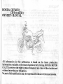
HONDA CB75OF2
CB SevenFiftv
_
OWNER'S MANUAL
J
All information
in this publication is based on the latest production
information available at the time of approval for printing. HONDA MoroR
co.,LTD. reserves the right to make changes at any time without notice and
without incurring any obligation.
No part of this publication may be reproduced without written permission.
+,
ol
WELCOME
The motorcycle presents you a challenge to master the machine, a challenge to
adventure.You ride through the wind, linked to the road by a vehicle that respondsto
your commandsas no other does.Unlike an automobile,there is no metal cage around
you. Like an airplane,a pre-rideinspectionand regular maintenanceare essentialto your
safety.Your reward is freedom.
you should become
To meet the challengessafely, and to enjoy the adventure fully,.YOU
RIDE THE
thoroughly familiai with ihis owner's' manual BEFORE
MOTORCYCLE.
your Honda dealerknows your motorcyclebest.
When serviceis required,rememberthat
"know-how"
If you have the required mechanical
and tools, your dealer can supply you
with an official Honda ServiceManual to help you perform many maintenanceand repair
tasks'
Pleasantriding, and thank you for choosinga Honda I
r2nce
ilsf rr2
IK
I G Germany I
ED E u r o p e a n d i r e c t
Finland
Denmark
sales
Belgium
Italy
Holland
Portugal
Greece
STr 5paln
(-.qnqrt
Tclrndc
U Australia
New Zealand
lrrrerlan
IIIG
iermanv I
SW Switzerland
. The specificationsmay vary with eachlocale.
J
€
€
1
1
1
1
2
z
Nnrwew
IIG Lrermany I
pa
1
1
2
2
IG...Fullpowertype
IIG...Limitedpowert.vpe
1
IIIG...Limitedpowertype
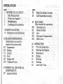
OPERATION
page
1 MOTORCYCLESAFETY
1
SafeRiding Rules
2
Protective Apparel
2
Modifications
3
Loading and Accessories
6 PARTS LOCATION
9
Instruments and Indicators
12 MAJORCOMPONENTS
(Information you needto
opetatethis motorcycle)
12 . Suspension
IJ
Brakes
TI
Clutch
19
Fuel
,2
Engine Oil
24
Tubeless Tyres
27 ESSENTIAL INDIVIDUAL
27
COMPONENTS
Ignition Switch
page
28
Right Handlebar Controls
29
Left Handlebar Controls
30 FEATURES
(Not required for operation)
30
Steering Lock
31 Helmet Holder
32
Seat
32
Document Compartment
33
SideCover
34 OPERATION
34
Pre-ride Inspection
35
Starting the Engine
38
Running-in
39
Ridins
4l
Braking
42
Parking
42
Anti-theft Tips
MAINTENANCE
page
43 MAINTENANCE
44
MaintenanceSchedule
47
Tool Kit
48
SerialNumbers
49
Colour Label
50
MaintenancePrecautions
51
Engine Oil
54
CrankcaseBreather
55
Spark Plugs
57
Throttle Operation
58
Idle Speed
59
Air Cleaner
60
Drive Chain
65
Drive Chain Slider
66
SideStand
67
Wheel Removal
74
Brake Pad Wear
76
Battery
79
Fuse Replacement
81
Bulb Replacement
page
87 CLEANING
89 STORAGE GUIDE
89
Storage
g0
Removal from Storage
91 SPECIFICATIONS
95 NOISE CONTROL SYSTEM
(AUSTRALIA ONLY)
MOTORCYCLE SAFETY
* Motorcygle riding requires
special efforts on ybur part to
ensure your safety. Know these
requirements before you ride:
SAFE RIDING RULES
l.Always make a pre-ride inspection
(page34) before you start the engine.
You may prevent an accident or
equipmentdamage.
2.Many accidentsinvolve inexperienced
riders. Most countriesrequire a special
motorcycleriding test or license.Make
gltrg-yquare qualilied before you ride.
NEVER lend your motorcycie to an
lnexperlenced
rlder.
3.Many automobile/motorcycle
accidents
happenbecause
the automobiledriver
"see"
doesnot
the motorcyclist.
Make yourself conspicriousto help
avoid the accident that wasn't your
f ault:
'
briglt or reflectiveclothing.
. W."..
D
on't ride in another motoiist's
"blind
spot."
4.Obey all national and local laws and
regulatlons.
e Excessivespeedis a factor in manv
g_cc!{g$s.Obey the speedlimits, anil
NEVER trave[ faster-thanconditions
warrant.
. Signalbeforeyou make a turn or lane
change.Your size and maneuverability can surpriseother motorists.
5.Don't let other motorists surprise vou.
Use extra caution at intersectibns,
parking lot entrancesand exits, and
orlvewavs.
6.Keep bolh handson the handlebarsand
both feet on the footpegswhile ridins.
A passengershould-h-oldon to thle
motorcycle or the operator with both
hands and keep bbth feet on the
passengerfootpegs.
PROTECTIVE APPAREL
1.Most motorcycle accident fatalities are
due to head injuries: ALWAYS wear a
helmet. You should also wear a face
shieldor gogglesas well as boots,gloves
and protective clothing. A passenger
needsthe sameprotection.
2. The exhaust system becomes hot
during operation,and it remainshot for
a while after stopping the engine. Be
careful not to touch the exhaustsystem
while it is hot. Wear clothing that fully
coversyour legs.
3.Do not wear looseclothing which could
catch on the control levers, footpegs,
drive chain or wheels.
MODIFICATIONS
* Modif ication of the motorcycle, or
removal of original equipment,
may render the vehicle unsafe or
illegal. Obey all national and local
equipment regulations.
L(
E
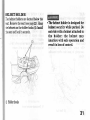
LOADING AND ACCESSORIES
*To prevent an accident, use
extreme care when adding and
riding with accessories and cargo.
Addition of accessories and cargo
can reduce a motorcycle's stability, performance and safe operating speed. Never ride an accessory-equipped motorcycle at speeds
above 13O km/h (8O mph). And
remember that this 13O km/h (8O
mph) limit may be reduced by
installation of non-Honda accessories, improper loading, worn tyres
and overall motorcycle condition,
poor road or weather conditions.
These general guidelines may
help you decide whether or how
to equip your motorcycle and how
to load it safely.
Loading
The combined weight of the rider,
passenger, cargo and additional accessories must not exceed the maximum
weight capacity:
190 kg (419 lbs)
Cargo weight alone should not exceed:
27 kg (60 lbs)
1. Keep cargo and accessory weight 1ow
and close to the center of the
motorcycle. Load weight equally on
both sides to minimize imbalance. As
weight is located further from the
motorcycle's center of gravity, handling
is proportionally affected.
2. Adjust tyre pressure (page24 ) and rear
suspension (page 12 ) to suit load weight
and riding conditions.
3. Vehicle handling and stability can be
adversely affected by loose cargo.
Recheck cargo security and accessory
mountsfrequently.
4. Do not attach large or heavy items
(such as a sleepingbag or tent) to the
handlebars,fork, or fender. Unstable
handling or slow steering responsemay
result.
Accessories
Genuine Honda accessorieshave been
specificallydesignedfor and testedon this
motorcycle. Because the factory cannot
t e s t a l l o t h e r a c c e s s o r i e s ,y o u a r e
personallyresponsiblefor proper selection,
installation, and use of non-Honda
accessories.
Always follow the guidelines
under Loading,and these:
1. Carefully inspectthe accessoryto make
sure it does not obscure any lights,
reduce ground clearance and banking
a n g l e , o r l i m i t s u s p e n s i o nt r a v e l ,
steeringtravel or control operation.
2.Large fork-mounted fairings or
windshields, or poorly designed or
improperly mounted f airings can
produceaerodynamicforces that cause
unstable handling. Do not install
fairings that decreasecooling air flow
to the engine.
3. Accessories which alter your riding
position by moving hands or feet away
from controls may increase reaction
time in an emergency.
4. Do not add electrical equipment that
will exceed the motorcycle's electrical
system capacity. A blown fuse could
cause a dangerous loss of lights or
engme power.
5. This motorcycle was not designed to
pull a sidecar or trailer. Handling may
be seriously impaired if so equipped.
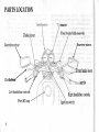
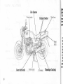
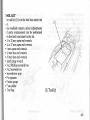
PARTS LOCATION
0meter
Choke lever
: ::
Front brake fluld reservdir
,Rearview'rnirror
Rearview mirr6r
\
/
Front brake lever
Ctur"t
:h levert"u"rr/(
$^..-
,/
grlp
/
L,eft handlebar control6
Right handlebar controls
Fuel fill cap
Ignition switch
Passcngpr footpeg
Rear brake oedal
'Oil'
f ifler cap/dipstick
7-
Air cleaner
Helmet holder
IN
IN
Th
ins
der
pat
(1
(2
(3
(4
(5
(6
(7
(8
(e
(10
(11
Gear shift pedal
Passengerfootpeg
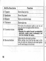
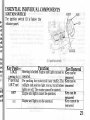
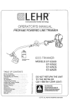
INST.RUMENTS AND
INDICATORS
The indicators are contained in the
instrument panel. Their functions are
described in the tables on the following
pages.
(1) Tripmeter
(2) Speedometer
(3) Odometer
(4) Tachometer
(5) Tachometer red zene
(6) Side stand indicator
(7) Low oil pressureindicator
(8) Turq sisnal indicator
(9) Neutral indicator
(10)fiigh beam indicator
(11) Tripmeter reset kirob
(,!,,(&'i'i
(Ref.No.) Description
Function
(1) Tripmeter
Showsmileageper trip.
(2) Speedometer
Showsriding speed.
(3) Odometer
Showsaccumulatedmileage.
(4) Tachometer
Showsenginerpm.
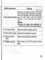
(5) Tachometerred zone
(6) Sidestand indicator
10
Never allow the tachometer needleto enter the red
zone,evenafter the enginehas beenbroken in.
GAUTION:
* Running the engine beyond recommended
maximum engine speed (tachometer red
zone) candamage the engine.
Lights when the side stand is put down.
Before parking, check that the side stand is fully
down; the light only indicatesthe side stand ignition
cut-off system(page35) is activated.
,,
\(
I
(1
(1
(Ref.No.) Description
Function
Lights vrhen the ertgine oil pressure is below the
normal operating range. Should light when ignition
switch is ON and engineis not running. Shouldgo out
(7) Low oil pressureindicator when the engine starts, except for occasional
flickering at or near idling speed when engine is
warm.
GAUTION:
* Running the engine with insufficient oil
pressure may cause serious engine damage.
(8) Turn signalindicator
Flasheswhen either turn signalis operated.
(9) Neutral indicator (green)
Lights when the transmissionis in neutral.
(10) High beam indicator
(blue)
Lights when the headlightis on high beam.
(11) Tripmeter resetknob
Resetstripmeter to zero (0). Turn knob in direction
snown.
17
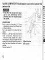
MAJOR COMPONENTS (Information
motorcycle)
you need to operate this
* If the Pre-ride Inspection (page
34 ) is not performed, severe
personal injury or vehicle damage
may result.
SUSPENSION
Each shock absorber ( 1) has
5 adjustmentpositionsfor different load
or riding conditions.
Use a pin spanner (2 ) to adjust the rear
shocks.
Position 1 is for light loads and smooth
road conditions. Positions 2 to
5 increase spring preload for a stiffer
rear suspension,
and can be usedwhen the
motorcycleis heavily loaded.Be certain to
adjust both shock absorbersto the same
position.
Standardposition:2
12
BR
Bot
hvd
-\s
levt
Tht
ilui
per
inst
nol
frer
bra
rec
pro
mu
dea
Frc
(1) Shock absorber
(2) Pin spanner
n
E
lls
I
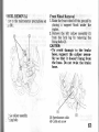
BRAKES
Both the front and rear brakes are the
irydraulic disc types.
-\s the brake pads weat', the brake fluid
level drops.
There are no adjustments to perform, but
,luid level and pad wear must be inspected
periodically. The system must be
:nspected frequently to ensure there are
ao fluid leaks. If the control lever or pedal
-ree travel becomes excessive and the
crake pads are not worn beyond the
recommended limit (pase74\, there is
probably air in the brake system and it
nust be bled. See your authorizedHonda
dealerfor this service.
Front Brake Fluid Level:
GAUTION:
* Handle brake fluid with care
because it can damage plastic and
painted surfaces.
* When adding brake fluid, be sure
the reservoir is horizontal before
the cap is removed or brake fluid
may spill out.
* Use only DOT 4 brake fluid from a
sealed container.
* Never allow contaminants such
as dirt or water to enter the brake
fluid reservoir.
* Brake fluid may cause irritation.
Avoid contact with skin or eyes.
In case of contact, flush thoroughly with water and call a doctor if
your eyes were exposed.
* KEEP OUT OF REACH OF CHIL.
DREN.
13
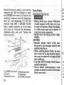
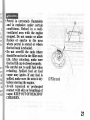
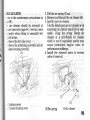
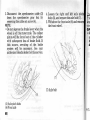
Brake fluid must be addedto the reservoir
whenever the fluid level begins to reach
the LOWER level mark ( 1). Remove the
screws(2 ), reservoircover (3 ), diaphragm
plate (4 ), and diaphragm (5 ). Fill the
reservoir with DOT 4 BRAKE FLUID
from a sealed container up to the upper
level mark (6 ). Reinstall the diaphragm,
diaphragm plate, and cover. Tighten the
screwssecurely.
(1)LOWER level mark (4) Diaphragm plate
(2)Screws
(5) Diaphragm
(3)Reservoircover
(6) UPPER ievel mark
14
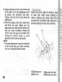
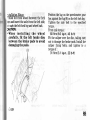
Rear Brake
RearBrake Fluid Level:
Ch
ins
col
pol
t Brake fluid may cause irritation.
Avoid contact with skin or eyes.
In case of contact, flush thoroughly with water and call a doctor if
your eyes were exposed.
* KEEP OUT OF REACH OF CHILDREN.
CAUTION:
x Handle brake fluid with care
because it can damage plastic and
painted surfaces.
* When adding brake fluid, be sure
the reservoir is horizontal before
the cap is removed or brake fluid
may spill out.
* Use only DOT 4 brake fluid from a
sealed container.
* Never allow contaminants such
as dirt or water to enter the brake
fluid reservoir.
(1)
Br
---1
:h
*ir
ie
iii
:
:11
.i
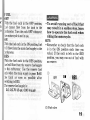
OtherChecks:
Make sure there are no fluid leaks. Check
for deterioration or cracks-irr.the hoses
and fittings.
CL
Clu
mo
or
cau
spe
wit
levr
Nor
1
(1) (
16
CLUTCH
Clutch adjustment may be required if the
riotorcycle stalls when shifting into gear
or tends to creep; or if the clutch slips,
causing acceleration to lag behind engine
speed.Minor adjustments can be made
with the clutch cable adjuster (4) at the
lever ( 1 ).
),iormalclutch lever free play is:
1O-2O mm (0.4-0.8 in)
l.Pull back the rubber dust cover (2).
Loosen the lock nut (3) and turn the
adjuster (4 ). Tighten the lock nut (3 )
and check the adjustment.
2.If. the adjuster is threaded out near its
limit or if the correct free play cannot
be obtained,loosenthe lock nut (3) and
turn in the cable adjuster (4 ) completely.
Tighten the lock nut (3 ) and install the
dust cover.
(1) Clutch lever
(A) Increasefree play
(2) Dust cover
(3) Lock nut
(B) Decreasefree play
(4) Clutch cable adjuster
17
3. Loosenthe lock nut (6 ) at the lower end
of the cable.Turn the adjustingnut (5)
to obtain the specified free play.
Tighten the lock nut (6) and check the
adjustment.
4. Start the engine,pull in the clutch lever
and shift into gear. Make sure the
engine doesnot stall and the motorcycle
does not creep. Gradually release the
clutch lever and open the throttle. The
motorcycle should begin to move
smoothlyand accelerategradually.
NOTE:
* If proper adjustment cannot be obtained
or the clutch does not work correctly,
seeyour authorizedHonda dealer.
Check the clutch cable for kinks or signs
of wear that could cause sticking or
failure. Lubricate the clutch cable with a
commercially availablecable lubricant to
prevent prematurewear and corrosion.
I
(5) Adjusting nut
(6) Lock nut
18
(A) Increasefree play
(B) Decreasefree play
IS
)r
o
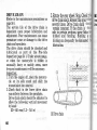
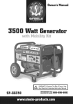
FUEL
OFF
-I
ith the fuel cock in the OFF position,
-rel cannot flow from the tank to the
:arburetor. Turn the cock OFF whenever
:ne motorcycleis not in use.
ON
T'ith the fuel cock in the ON position, fuel
:rill flow from the main fuel supply to the
:arburetor.
RES
With the fuel cock in the RES position,
:uel will flow from the reserve fuel supply
:o the carburetor. Use the reserve fuel
rnly when the main supply is gone.Refill
:he tank as soon as possible after
switchingto RES.
Ihe reservefuel supplyis:
3.0 0 (0.79 USsal,0.66 tmpgat)
* To avoid running out of fuel that
may result in a sudden stop, learn
how to operate the fuel cock when
ridirlg the motorcycle.
NOTE:
* Rememberto check that the fuel cock
is in the ON position each time you
refuel. If the cock is left in the RES
position, you may run out of fuel with
no reserve.
0il
(1) Fuel valve
RES
@
19
Fuel Tank
The fuel tank capacity including the
reservesupplyis:
2O.O0 (5.28US gal,4.4O lmp gal)
To open the fuel fill cap (1), insert the
ignition kev Q) and turn it clockwise.The
fuel fill cap is hinged and will lift up.
(1) Fuel fill cap
(2) Ignition key
(3) Fi1lerneck
20
After refueling,to closethe fuel fill cap,l
push the fuel lill cap into the filler neckl
until it snaps closed and locks. RemoveI
the key.
Use unleaded or low-lead petrol with a
research octane number of 91 or higher.
We recommend that you use unleaded
petrol becauseit producesfewer engine
and spark plug depositsand extends the
life of exhaustsystemcomponents.
FOR AUSTRALIA ONLY:
Use unleaded petrol with a research
octanenumber of 91 or higher.
GAUTION:
* If ttspark knockt'or "pinking" occurs at a steady engine speed under normal load, change brands of
petrol. If spark knock or pinking
persists, consult your authorized
Honda dealer. Failure to do so is
considered misuse, and damage
caused by misuse is not covered
by Honda's Limited Warranty.
.Pe
an
col
Yel
stc
fla
wb
th(
'Do
sh(
(3)
thr
.Be
rel
val
spi
beI
.Av
cor
val
CH
'Petrol
is extremely
flammable
and is explosive under certain
conditions.
Refuel in a wellventilated area with the engine
stopped. Do not smoke or allow
flames or sparks in the area
where petrol is stored or where
the fuel tank is refueled.
. Do not overfill
the tank (there
should be no fuel in the filler neck
(3)). After refueling, make sure
the fuel fill cap is closed securely.
. Be careful not to spill fuel when
refueling.
Spilled fuel or fuel
vapor may ignite. If any fuel is
spilled, make sure the area is dry
before starting the engine.
. Avoid repeated or prolonged
contact with skin or breathing of
vapor. KEEP OUT OF REACH OF
CHILDREN.
(3) Filler neck
21
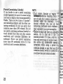
Petrol Containing Alcohol
I{ fou decide to use a petrol containing
alcohol(gasohol),be sure it's octanerating
is at least as high as that recommendedby
Honda.There are two types of "gasohol":
one containing ethanol, and the other containing methanol. Do not use petrol that
contains more than 1070ethanol. Do not
use petrol containingmethanol(methyl or
wood alcohol) that does not also contain
cosolvents and corrosion inhibitors for
methanol. Never use petrol containing
more than 590 methanol, even if it hai
cosolventsand corrosion inhibitors.
22
NOTE:
* Fuel system damage or engine
formance problems resulting from t
formance
use of fuels that contain alcohol is r
covered under the warrantv.
cannot endorse the use of fuel
containing methanol since evidence
their suitability is as yet incomplete.
* Before buying fuel from an unfamili
station, try to find out if the f
containsalcohol.If it does,confirm t
type and percentage of alcohol used.
you notice any undesirable operati
symptoms while using a petrol tl
contains alcohol,or one that you thi
contains alcohol, switch to a petrol th
you know doesnot contain alcohol.
gir
rcl
he
eup
e dit
Stal
lunr
E.an
iemi
Stop
ira
grou
-{fte
iller
:eins
ia.R
sirou
narl
Ir re
page
-ot o
)er
E\GINE OIL
Engine Oil Level Check
Checkthe engineoil level eachday before
::ding the motorcycle.
The level must be maintained between
Lre upper( 1 ) and lower (2 ) level marks on
i-:e dipstick (3).
^- Start the engine and let it idle for a few
minutes. Make sure the oil pressure
warning red light goes off. if the light
remains on, stop the engine immediately.
l. Stopthe engineand hold the motorcycle
in an upright position on firm, level
ground.
::. After a few minutes, remove the oil
filler cap/dipstick, wipe it clean, and
reinsert the dipstick without screwing it
in. Remove the dipstick. The oil level
shouldbe betweenthe upper and lower
marks on the dipstick.
4. If required, add the specified oil (see
page51 ) up to the upper level mark. Do
not overfill.
5. Reinstall the oil filler cap/dipstick.
Check for oil leaks.
CAUTION:
* Running the engine with insufficient oil pressure may cause serious engine damage.
(1) Upper level mark
(2) Lower level mark
(3) Oil filler cap/dipstick
23
TUBELESSTYRES
This motorcycle is equippedwith tubeless
and wheel rims. Use only
tyres, valves,"TUBELESS"
and tubeless
tyres marked
"TUBELESS
valves on rims marked
TYRE APPLICABLE.''
Proper air pressurewill provide maximum
stability, riding comfort and tyre life.
Check tyre pressurefrequently and adjust
if neccessary.
NOTE:
* Tyre pressureshould be checked before
you ride while the tyres are "cold".
* Tubeless tyres have some degree of
selfsealingability if they are punctured,
and leakage is often very slow. Inspect
very closely for punctures, especially if
the tyre is not fully inflated.
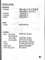
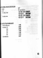
Tyre size
Front
120t70R178V
1201702R17
150/70R17 69V
1ml70zR17
Cold tyre pressures
kPa (kg/cm', psi)
Front
Rear
25O(2.5O,36)
25O(2.5O,36)
Driver and
Front
one passenger Rear
25O(2.5O,36)
29OQSO ,421
Driver
only
Tyre brand
TUBELESS ONLY
24
DUNLOP
Front
Rear
D2O2F
D2O2
MICHELIN
Front
Rear
A89X
M89X
Chr
Dr
eier
dar
Ce
bal
T
E
rf
a
s
n
o
t:
Ir
rI
t1
v
d
EI
Tyre Repair/Replacement:
Seeyour authorizedHonda Dealer.
* The use of tyres other than those
listed on the tyre information label may adversely affect handling.
* De not install tube-type tyres on
tubeless rims. The beads may not
seat and the tyres could slip on
the rims, causing tyre deflation
that may result in a loss of vehicle
control.
* Do not install a tube inside a
tubeless tyre. Excessive heat
build-up may cause the tube to
burst resulting
in rapid tyre
deflation that may result in a loss
of vehicle control.
* Replace the tyre if the sidewall is
punctured or damaged. Sidewall
flexing may cause repair failure
and tyre deflation that may result
in a loss of vehicle control.
26
IG
* Proper wheel balance is necessary for safe, stable handling of the
motorcycle. Do not remove or
change any wheel balance
weights. When wheel balancing is
required, see your authorized
Honda dealer. Wheel balancing is
required after tyre repair or
replacement.
x To avoid possible repair failure
and tyre deflation that may result
in a loss of vehicle control, do not
exceed 8O kmih (5O mph) for the
first 24 hours, or 130 km/h (8O
mph) at any time, after tyre repair.
GAUTION:
* Do not try to remove tubeless
tyres without special tools and
rim protectors, You may damage
the rim sealing surface or
disfigure the rim.
tn
rd
I
(
ESSENTIAL INDIVIDUAL COMPONENTS
tle'
IGNITION SWITCH
lhe ignition switch (1) is below the
'rdicatorpanel.
)r
:e
is
:d
is
)r
re
Llt
ot
ne
Kev Posit
LOCK
erins ll
P (parking)
(AR Type)
nd
ge
or
OFF
Function
Steeringis locked.Engine and lights cannotbe
operated.
For parking the motorcycle near traffic. The
taillight and position light are on, but all other
lights are off. The ensine cannot be started.
Key Removal
Key can be
removed
Key can be
removed
Engine and lights cannot be operated.
Key can be
removed
Engine and lights can be operated.
Key cannot be
removed
27
RIGHT HANDLEBAR CONTROLS
Engine Stop Switch
The engine stop switch (1) is next to the
throttle grip. When the switch is in the
RUN position, the engine will operate.
When the switch is in the OFF position,
the enginewill not operate.This switch is
intended primarily as a safety or emergency switch and should normally remain in
the RUN position.
Headlight Switch (ExcePt U tYPe)
The headlisht switch (2) has three
postions;"H", "P" and "OFF" marked by
"P".
a dot to the right of
H: Headlight, taillight, position
light and meter lights on.
P: Position light, taillight and
meter lights on.
OFF (dot):Headlight, taillight, position
light and meter lights off .
2A
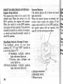
Starter Button
The starter button (3) is below the head
light switch (2).
When the starter button is pressed,the
starter motor cranks the engine. If the
enginestop switch is in the OFF position,
the starter motor will not operate. See
page36 for the starting procedure.
LE
Ee
P.rs
rigl
Pat
il-h
i-^
id5
rht
!li
Tur
\Io,
: rir
Eor
Fre
(1) Engine stop switch
(2) Headlight switch
(3) Starter button
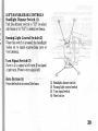
LEFT HANDLEBAR CONTROLS
Headlight Dimmer Switch (1)
"HI"
Push the dimmer switch to
to select
"LO"
righ beam or to
to selectlow beam.
e
L,
e
Passing Light Control Switch (2)
Then this switch is pressed,the headlight
-lashes on to signal approaching cars or
-.r-hen
passing.
Turn Signal Switch (3)
\Iove to L to signal a left turn, R to signal
. right turn. Pressto turn signal off.
Horn Button(4)
Pressthe button to soundthe horn.
(1) Headlight dimmer switch
(2) Passinglight control switch
(3) Turn signal switch
(4) Horn button
29
FEATURES
(Not required for operation)
STEERING LOCK
T" Git the steering,turn the handlebars
uff tttJ*uv to the left or right, r,trrnthe
t "v (tl to'P or LOCK while pushingin'
Removethe key.
* no oot torn the keY to P or LOCK
wftit" riding the mo-torcycle; loss
"fvetti"t.
cdntrol will result'
(1) IgnitionkeY
(A) Pushin , '
(B) Turn to LOCK
HELMET HOLDER
The helmet holders are located below the
-at. Removethe seat (seepage32).Hang
:'oehelmetson the holder hooks(1).lnstall
:he seatand lock it securelv.
* The helmet holder is designed for
helmet security while parked. Do
not ride with a helmet attached to
the holder; the helmet may
interfere with safe operation and
result in loss of control.
'i) Holder hooks
31
SEAT
To remove the seat (1),insert the ignition
key into the seat lock (2) and turn it
clockwise . Pull the seat back and up. To
install the seat, insert the prong into the
recessunder the frame crossmember and
then pushdown on the rear of the seat.
GAUTION:
* Be sure the seat is locked
securely in position after installation.
e)
DOCUMENT COMPARTMENT
The document bag is placed underneath
the seat inside the tray besidethe tool bag.
To accessthe document,pull the tray out.
This owner's manual and other documents should be stored in the compartment.
When washing your motorcycle, be careful not to flood this areawith water.
SII]
lfhe
-ie
:nai
:.R
t.R
i. P
ru
(1
(1
(1) Document compartment
(1) Seat
32
(2) Seatlock
l, S
!rS
0
;
t-
SIDE COVER
The side cover (1) must be removed for
,le battery and air cleaner element
:raintenance.To removethe sidecover:
-.Removethe seat.
l. Removethe screw (2).
l.Pull the retaining tabs (3) out from the
rubber holes and remove the side cover
(i).
1) Side cover
2) Screw
NOTE:
* Do not pull on the side cover with the
screw(2 ) installed.
(3) Retaining tabs
33
OPERATION
PRE.RIDE INSPECTION
* If the Pre-ride Inspection is not
performed, severe personal injury
or vehicle damage may result.
Inspect your motorcycle every day before
you ride it. The items listed here will only
take a few minutes to inspect,and in the
long run they can save time, expense,and
possiblyyour life.
1. Engine oil level-add engine oil if
required(page23). Check for leaks.
2 .F u e l l e v e l - f i l l f u e l t a n k w h e n
necessary(page19). Checkfor leaks.
3. Front and rear brakes-check operation: make sure there is no brake fluid
leakase(pages 13-16).
4. Tyres-check conditionand pressure
(pase 24).
5. Drive chain-check condition and slack
(page60 ). Adjust and lubricate if
necessary.
6.Throttle-check for smooth opening
and full closing in all steering positions.
7, Lights and horn-check that headlight,
tail/brake light, turn signals, indicators
and horn function properly.
8.Engine stop switch-check for proper
function (page 28).
9. Side stand ignition cut-off systemcheckfor properfunction (page 66).
Correct any discrepancybefore you ride.
Contact your authorizedHonda dealerfor
assistance if you cannot correct the
problem.
STI
T'his
-<fanl
ianrl
:de
=de
:a n(
g:llt
Sanl
:rzlnl
:]re s
;li
E
*\[
el
c(
m
ol
dt
\01
.D(
th
SC
34
if
1g
rt,
)rs
)er
t-
de.
for
:he
STARTING THE ENGINE
lhis motorcycle is equipped with a side
.:and ignition cut-off system. The engine
-annot be started if the side stand is down.
:nlessthe transmissionis in neutral.If the
':de stand is up, the engine can be started
-r neutral or in gear with the clutch lever
-.-rlledin. After starting with the side
;:and down, the engine will shut off if the
:ransmission is put in gear before raising
:he side stand.
Before starting, insert the key, turn the
ignition switch ON and confirm the
following:
o The transmission is in NEUTRAL
(neutral indicator light ON).
r The engine stop switch is at RUN.
r The red low oil pressureindicator is ON.
r The fuel cock is ON.
. Never run the engine in an
enclosed area. The exhaust
contains poisonous carbon
monoxide gas that can cause loss
of consciousness and lead to
death.
NOTE:
* Do not use the electric starter for more
than 5 seconds at a time. Release the
starter button for approximately 10
secondsbefore pressingit again.
35
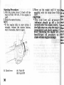
Starting Procedure
1.Pull the choke lever (1) back all the
way to Fully ON (A), if the engine is
cold.
2. Pressthe starter button.
NOTE:
* If the engine fails to start within 5
seconds, release the starter button,
wait 10 seconds,then try again.
(1) Choke lever
36
(A) Fullv ON
(B) Fully OFF
3.Tfarm up the engine'until it runs
smoothly, with the choke lever Fully
OFF.
GAUTION:
* T h e r e d l o w o i l -off
Dressur
indicator should go
a fer
seconds after the engine starts.
the light stays on, stop the engir
-immediately and crheck engine (
level. -Oqerating_the engint wit
insuff icient oil pressure ca
cause serious engine darnage.
Floo
ff the
:ttefi
fuel.'
agin
chokt
Open
engin
gurck
drght
does
follora
. looded Engine
the engine fails to start after repeated
,tempts, it may be flooded with excess
-el. To clear a flooded engine,leave the
-.-ginestop switch on RUN and push the
-oke lever forward to Fullv OFF (B).
:en the throttle fullY and crank the
.:.ginefor 5 seconds.If the engine starts'
-ickly close the throttle, then open it
ghtly if idling is unstable. If the engine
es not start, wait 10 seconds, then
iow the Starting Procedure.
37
RUNNING.IN
During initial running-in newly machined
surfaceswill be in contactwith eachother
and these surfaces will wear in quicklv.
Running-in maintenanceat 1,000km(6d0
miles) is designedto compensatefor this
initial minor wear. Timely performanceof
the running-in maintenance will ensure
optimum service life and performance
from the engine.
The generalrules are as follows:
1. Never labour the engine with full
throttle at low enginespeeds.This rule
is applicable not only during running-in
but at all tirnes.
2. Maximum continuous engine speed
during the first 1,000 km ( 600 miles)
must not exceed5,000min-l (rpm).
3. Increase the maximum continuous
engine speed by 2,000 mini (rpm)
between odometer readings of
1,000 km ( 600 miles) and 1.600km
( t,000 miles).Drive briskly, vary speeds
frequently and usefull throttle forihort
bursts only. Do not exceed 7,000 min-l
(rpm).
38
4. Upon reaching an odometer reading
1,600km ( 1,000miles),you can subj
the motorcycle to full throttle operati
However, do not exceed 8,600rpm
any time (tachometerred zonelimit).
CAUTION:
* Running the engine beyond
mended maximum engine
(tachometer red zone) can
the engine.
RIT
TI
I
rf,
I
NOl
.\I
of
Il
pa
S1
i.ll
rh
l.w
ch
pe
l. Sl
thr
en
Co
lel
4.W
at(
clr
rai
Th
siv
RIDING
@
.
Review Motorcycle Safety (pages
I - 5)beforeyouride.
\OTE:
' Make sure you understand the function
of the side stand mechanism. (See
MAINTENANCE SCHEDULE on
page 45 and explanation for SIDE
STAND on pase 66 )
' After the engine has been wanned up,
the motorcycle is ready for riding.
l. While the engine is idling, pull in the
clutch lever and depress the gearshift
pedal to shift into 1st (low) gear.
3.Slowly release the clutch lever and at
the same time gradually increase
engine speed by opening the throttle.
Coordination of the throttle and clutch
lever will assurea smooth positive start.
l.When the motorcycle attains a moderate speed,close the throttle, pull in the
clutch lever and shift to 2nd gear by
raising the gearshift pedal.
This sequence is repeated to progressively shift to 3rd, 4th and 5th (top)
gears.
5. Coordinatethe throttle and brakes for
smooth deceleration.
6. Both front and rear brakes should be
used at the same time and should not
be applied strongly enough to lock the
wheel, or braking effectiveness will be
reduced and control of the motorcvcle
be difficult.
W
39
* Do not downshift when traveling
at a speed that would force the
engine to overrev in the next
lower gear; the rear wheel may
lose traction,
resulting
in a
possible loss of vehicle control.
GAUTION:
* Do not shift gears without disengaging the clutch and closing the
throttle. The engkre and drive
train could be damaged by overspeed and shock.
* Do not tow the motorcycle
or
coast for long distances while the
engine is off. The transmission
will not be properly lubricated
and damage may result.
* Do not ride over a curb or rub the
wheel against an obstacle, as
wheel damage may result.
40
NOTE:
* The battery will not charge while
engine speedis near idle speed.A
idling for prolongedperiods.
.{.
For
botl
*ow
For
:hrc
-lral
5efc
FE\
* Ind
or
Fer
tltn r
redr
cle.
Shr
hra
cloc
mid
Fhr
the
IE
id
: R^{KING
lor normal braking, gradually apply
:oth the front and rear brakes while
:ownshifting to suit your road speed.
- ior maximum deceleration,close the
,hrottle and apply the front and rear
rrakes firmly. Pull in the clutch lever
refore coming to a complete stop to
3reventstalling the engine.
. Independent use of only the front
or rear brake reduces stoppiag
performance.
Extreme braking
may cause either wheel to lock,
reducing control of the motorcycle.
. When possible, reduce speed or
tlrake before entering a turn;
closing the throttle or braking in
mid-turn may cause wheel slip.
Wheel slip will reduce control of
the motorcycle.
* When riding in wet or rainy conditions, or on loose surfaces, the
ability to maneuver and stop will
be reduced. All of your actions
should be smooth under these
conditions. Rapid acceleration,
braking or turning may cause loss
of control. For your safety, exercise extreme caution when
braking, accelerating or turning.
* When descending a long, steep
grade, use engine compression
braking by downshifting,
with
intermittent
use of both brakes.
Continuous brake application can
overheat the brakes and reduce
their effectiveness.
* Riding with your foot resting on
the brake pedal or your hands on
the brake lever may actuate the
giving a false
brakelight,
indication to other drivers. It may
also overheat the brake, reducing
effectiveness.
41
!L
P.TRKING
1.-d:rer stoppingthe motorcycle,shift the
:ransmissioninto neutral, turn the fuel
cock OFF, turn the handlebarfully to
the left, turn the ignition switch OFF
and removethe key.
2.Use the side or center stand to support
the motorcyclewhile parked.
CAUTION:
* Park the motorcycle
on f irm,
level ground to prevent it from
falling over.
* If you must park on a slight incline, aim the front of the motorcycle uphill to reduce the
possibility of roiling off the side
stand or overturning.
3.Lock the steeringto help prevent theft
(page30 ).
ANTI.THEFT TIPS
1.Always lock the steering and never
leave the key in the ignition switch.
This soundssimplebut peopledo forget.
2. Be sure the registrationinformation for
your motorcycle is accurate and
current.
3. Park your motorcycle in a locked
garagewheneverpossible.
4.Use an additionalanti-theft device of
goodquality.
5. Put your name, address,and phone
number in this Owner's Manual and
keep it on your motorcyclesat all times.
Many times stolen motorcycles are
identified by information in the Owner's
Manualsthat are still with them.
NAME:
ADDRESS:
P H O N EN O :
42
r l
:
:
o l
,,IAINTENANCE
r
I
u
rf
e
d
' lhe Required Maintenance Schedule specifies how often you
should have your
lotorcycle served,and what things needattention.It is essentialthat .vourmotorcycle
'e served as scheduledto retain its high level of safety, dependability',and emission
:ontrol performance.
' lhese instructions are based on the assumptionthat
the motorcl-cle will be used
.rclusively for its designedpurpose.Sustainedhigh speedoperation.or operationin
:nusually wet or dusty conditions,will require more frequent sen ice than specifiedin
-re MAINTENANCE SCHEDULE. consult your authorized Honda dealer for
::commendationsapplicableto your individual needsand use.
S
43
1-I
I
I
I
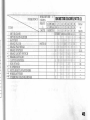
rr-rn{TENANCE SCHEDULE
peak
f"" following Maintenance Schedule specifies al1 maintenance required to keep your motorcycle in
.on-ditior. Maintenance work should be performed in accordancewith standards and specificationsof
;;;";G
tiorda ly properly trained and equipped technicians. Your authorized Honda dealer meets all of these
requirements:
Perform the Pre-ride Inspection(page34 ) at eachscheduledmaintenanceperiod'
I: INSPECT AND CLEAN, ADJUST, LUBRICATE OR REPLACE IF NECESSARY
:l
ODOMETER READING TNOTE(1)]
-.
-r
+4
ODOMETERREADINGINOTE(1)]
45
*
SHOULD BE SERYICED BY YOUR AUTHORIZED HONDA DEALER, UNLESS THE OWNER HAS
PROPER TOOLS AND SERVICE DATA AND IS MECHANICALLY QUALIFIED. REFER TO THE
OFFICIAL HONDA SHOP MANUAL.
* * IN THE INTEREST OF SAFETY, WE RECOMMEND THESE ITEMS BE SERVICED ONLY BY YOUR
AUTHORIZED HONDA DEALER.
]e
_:€a
Honda recommends that your authorized Honda dealer should road test your motorcycle after each periodic
maintenanceis carried out.
ild
qtl
o1(
NOTES:
(1)
(2)
(3)
(4)
(s)
At higher odometerreadings,repeat at the {requency interval establishedhere.
Service more frequently when riding in unusually wet or dusty areas.
Service more frequently when riding in rain or at fuli throttie.
Switzerland and Austria type only.
Replace every 2 years, or at indicated odometer interval, whichever comes first. Replacement
requires mechanicalskill.
TO
fun
. 1.
r$
t)!
.:l
oS
r \
. \ i
o!4
opi
.Ft
r F'r
rTr
46
IOOL
KIT
-retool kit (1) is in the tool box under the
':3L.
:.ne roadsiderepairs,minor adjustments
.,-Cparts replacementcan be performed
- .:h the tools containedin the kit.
. 10x 12 mm open end wrench
, i4x17 mm openend wrench
. 3 mm open end wrench
, i2mm box end wrench
. 24 mm box end wrench
. Spark plug wrench
. \o.2 Phillips screwdriver
. \o.2 screwdriver
. Screwdriver grip
. Pin spanner
. Feelergauge
. Fuse puller
. Tool bag
(1) Tool kit
SERIAL NUMBERS
The frame and engine serial numbersare
required when registering your motorcycle. They may also be required by your
dealerwhen orderingreplacementparts.
Record the numbers here for your
reference.
The frame number (1) is stamped on
right side of the steering head.
FRAMENO.
ENGINE NO.
(1) Frame number
(2) Engine number
4a
The engine number (2) is stamped on t
right side of the crankcase.
.OLOUR LABEL
lhe colour label (1) is attached to the left
-:amerail under the seat.
-: is helpful when ordering replacement
-zrts. Recordthe colour and codehere for
,ur reference.
-OLOUR
-I]DE
Colour label
49
MAINTENANCE
@@
*
your
PRECAUTIONS
If
motorcycle is overturned
or involved in a collision, inspect
control levers. cables. brake
hoses, calipers, accessories, and
other vital parts for damage. Do
not ride the motorcycle if damage
impairs safe operation. Have
your authorized
Honda dealer
inspect the major components,
including frame, suspension and
steering parts, for misalignment
and damage that you may not be
able to detect.
* IJse new, genuine Honda parts or
their equivalent for maintenance
and repair. Parts which are not of
equivalent quality may irnpair
the safety of your motorcycle.
*Stop the engine and support the
motorcycle securely on a firm,
level surface before performing
any maintenance.
50
E\GINE OIL
l:-efer to the maintenanceprecautionson
F , : 4 eb u r .
f,ngine Oil
'..rd engine oil has many desirable
:alities.Use only high detergent,quality
':or oil certified on the container to
::et or exceed requirements for API
.:l'ice ClassificationSE, SF or SG.
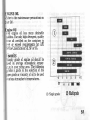
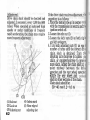
-iscosity:
.cosity grade of engine oil should be
.-d on average atmospheric temper,':re in your riding area. The following
-,rides a guide to the selection of the
-per grade or viscosity of oil to be used
-.ariousatmospherictemperatures.
20
(1) Single grade
tl
||11
(2) Multigrade
51
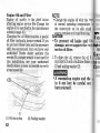
Engine Oil and Filter
Engine oil quality is the chief factor
affecting engine service life. Change the
engineoil as specifiedin the maintenance
schedule(page45 ).
Changing the oil filter requires a special
oil filter tool and a torque wrench. If you
do not have these tools and the necessarv
skill, we recommendthat -vou have vour
authorized Honda dealer perform this
service. If a torque .wrenchis not used for
this installation, see your authorized
Honda dealer as soonas possibleto verifv
proper assembly.
-.--------"--------.-
52
1. To drain the oil, remove the oil fi
cap/dipstickand crankcasedrain
(1) and sealing washer (2) .
* A warmed-up engine and the
in it are hot; be careful not
burn yourself.
(2)
(1) Oi1drain plug
NOTE:
* Change the engine oil with the
at normal operating temperature
the motorcycle on its side stand
assurecompleteand rapid draining.,
CAUTION:
* To prevent oil leaks and
damage, never support the
on the oil filter.
(2) Sealingwasher
rC
f,sin€
@te
lo
fse o
=ltt
l0r5 Jo
fuer
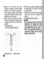
i =nove the oil filter (3 ) with a filter
':ench and let the remaining oil drain
:-. Discardthe oil filter.
--?ply a thin coat of engine oil to the
oil filter rubber seal (4 ).
.:n'--:ing
a special tool and a torque
i:ench, install the new oil filter and
.:ghtento a torque of:
1O N'm (1.0 kg-m, 7 lb-ft)
, se only the Honda genuine oil filter or
: filter of equivalent quality specified
,..,ryour model.Using the wrong Honda
-lter or a non-Honda filter which is not
-: equivalentquality may causeengine
iamage.
5. Check that the sealing washer on the
drain plug is in good condition and
install the plug. Replace the sealing
washer every other time the oil is
changed,or eachtime if necessary.
Oil Drain Plug Torque:
35 N'm(3.5kg-m,25 lb-ft)
6. Fill the crankcase with the recommendedgradeoil; approximately:
3.0 0 (3.2 US qt , 2.6 lmp qt)
7. Install the oil filler cap.
8. Start the engine and let it idle for 2-3
minutes.
9. Several minutes after stopping the
engine, check that the oil level is at the
upper level mark on the dipstick with
the motorcycle upright on firm, level
ground. Make sure there are no oil leaks.
(4
(3) Oil filter
(4) Oil filter rubber seal
53
NOTE:
* When running in very dusty conditions,
oil changes should be perfomed more
frequently than specified in the
maintenanceschedule.
* Please dispose of used engine oil in a
manner that is compatible with the
environment.We suggestyou take it in
a sealed container to your local recycling center or service station for reclamation. Do not throw it in the rubbish
or pour it on the ground or down a drain.
CAUTION:
* Used engine oil may cause skin
cancer if repeatedly left in contact with the skin for prolonged
periods. Although this is unlikely
unless you handle used oil on a
daily basis, it is still advisable to
thoroughly wash your hands with
soap and water as soon as possible after handling used oil.
CRANKCASE BREATHER
(Referto the maintenance
precautions
page50).
1. Remove the crankcase breather
plug (1) from the tube and
depositsinto a suitablecontainer.
2. Reinstall the crankcase breather
plug.
NOTE:
* Servicemore frequently when riding
rain or at full throttle.
;;:>//7'a\
ltt' (i'
I
"a/i_,+
-=-i
:a*1-
tl
\
(1)
(1) Crankcasebreather tube plug
54
-{R
ier
e5(
sanr
DP
x2
F,are
DP
x2
3. Inspect the electrodes and center
porcelainfor deposits,erosionor cabon
fouling. If the erosion or deposit is
heavy,replacethe plug. Clean a carbon
or wet-fouled plug with a plug cleaner,
otherwiseuse a wire brush.
4.Check the spark plug gap (2) using a
wire-type feeler gauge.If adjustmentis
necessary,bend the side electrode (3 )
carefully.
The gap shouldbe:
0.8-0.9 mm (0.03-0.04 in)
(2) Spark plug gap
56
(3) Side electrode
5. S/ith the plug washer attached,thread
the spark plug in by hand to prevent
cross-threading.
6. Tighten the spark plus U2 turn with a
spark plug wrench to compress the
washer.
7. Reinstallthe spark plug caps.
CAUTION:
* The spark plug must be securely
tightened.
An improperly
tightened plug can become very hot
and possibly damage the engine.
* Never use a spark plug with an improper heat range. Severe engine
damage could result.
:HROTTLE OPERATION
, .:er to the maintenance
precautions
on
I i . = 5 0) .
- eeck for smooth rotation of the
' rottle grip from the fully open
to the
,-ly closedposition at both full steering
.,.sitions.
- leasure the throttle grip free play at
- e throttle grip flange.
-e standard free play should be
r -?rox:
2.0-6.0 mm (0.08-0.24 in)
- -,adjust the play, loosenthe lock nut
- and turn the adjuster(2 ).
(1) Lock nut
(2) Adjuster
57
IDLE SPEED
(Refer to the maintenanceprecautionson
page50).
The engine must be at normal operating
temperature for accurate idle speed
adjustment. Ten minutes of stop-and-go
riding is sufficient.
NOTE:
* Do not attempt to compensatefor faults
in other systemsby adjusting idle speed.
See your authorized Honda dealer for
regularly scheduled carburetor
adjustments, including individual
carburetor adiustment and
synchronization.
1. Warm up the engine, shift to neutral
and place the motorcycle on its center
stand.
2. Adjust idle speedwith the throttle stop
screw( 1).
Idle speed(In neutral):
1,20O+1OO
min-l(rpm)
1,20O+5Ominj(rpm) ( SW Type )
58
,;ru
tiV'.
AIR
{Ref,
mrge
The
\Ol
\ _14
l-'r-[
(1) Throttle stop screw (A) Increase
(B) Decrease
GCS]r
freqr
EdU
LRe
fRe
cle
,]IR CLEANER
i .:er to the maintenanceprecautionson
rre50).
-:=
air cleaner should be serviced at
'iiar intervals (page44). Service more
.:=lently when riding in unusually wet
- jsty areas.
.-,:movethe left sidecover.
,'.:movethe attaching screws(l)and air
,.:aner housingcover(2).
.-::aching screws
-,: cleaner housing cover
3. Pull the set spring (3) out.
4. Remove and discard the air cleaner (4).
5. Install a new air cleaner.
Use the Honda genuine air cleaner or an
equivalent air cleaner specified for your
model. Using the wrong Honda air
cleaner or a non-Honda air cleaner
which is not of equivalent quality may
cause premature engine wear or
performance problems.
6. Install the removed parts in reverse
order of removal.
(3) Set spring
(4)Air cleaner
59
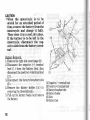
DRIVE CHAIN
(Refer to the maintenanceprecautionson
page50).
The service life of the drive chain is
dependent upon proper lubrication and
adjustment.Poor maintenancecan cause
premature wear or damage to the drive
chain and sprockets.
The drive chain should be checked and
lubricated as part of the Pre-ride
Inspection(page34 ). Under severeusage,
or when the motorcycle is ridden in
unusually dusty or muddy areas, more
frequent maintenancewill be necessary.
Inspection:
1. Turn the engine off, place the motorcycle on its side stand and shift the
transmissioninto neutral.
2. Check slack in the lower drive chain
run midway between the sprockets.
Drive chain slack should be adjustedto
allow the following vertical movement
by hand:
30-40 mm (1.2-1.6 in)
60
3. Rotate the rear wheel. Stop. Check t
drive chain slack. Repeat this proc
severaltimes. Drive chain slack
remain constant. If the chain is
only in certain sections, some links
kinked and binding. Binding a
kinking can frequently be eliminated
lubrication.
(1) Drive chain
Rr
fll
:OI
lotate the rear wheel slowly and
ispect the drive chain and sprockets
-,,r any of the following conditions:
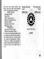
DRIVE CHAIN
*DamagedRollers
*LoosePins
*Dry or Rusted Links
*Kinked or Binding Links
*ExcessiveWear
*Improper Adjustment
tMissing O-rings
SPROCKETS
*ExcessivelyWorn Teeth
*Broken or DamagedTeeth
-;ive chain with damaged rollers, loose
::. or missingO-ringsmust be replaced.
,:ain which appearsdry, or showssigns
:--lst, requires supplementary lubrica: Kinked or binding links should be
r :rughly lubricated and worked free. If
'.. cannot be freed, the chain must be
" aced.
DamagedSprocket
Teeth
Worn Sprocket
Teeth
REPLACE
REPLACE
#*
Normal Sprocket
GOOD
61
Adjustment:
Drive chain slack should be checked and
adjusted,if necessary,every 1,000km (600
miles). When operated at sustainedhigh
speeds or under conditions of frequent
rapid acceleration,the chain may require
more frequent adjustment.
(2)
(1) Axle nut
(2) Lock nut
(3) Adjusting nut
62
(5)
(4) Index mark
(5) Rear edse of
adjusting slot
If the drive chain requiresadjustment,t
procedureis as follows:
l. Placethe motorcycleon its center
with the transmissionin neutral and t
ignition switch off .
2. Loosenthe axle nut (1).
3. Loosen the lock nuts (2) on both rig
and left swingarm.
4.Turn both adjusting nuts (3) an equ
number of turns until the correct dri
chain slack is obtained. Turn t
adjusting nuts clockwise to tighten
chain, or counterclockwise to provi
more slack. Adjust the chain slack at
point midway between the dri
sprocket and the rear wheel sprock
Rotate the rear wheel and
slack at other sectionsof the chain.
Chain slack shouldbe:
30-40 mm (1.2-1.6 in)
-heck rear axle alignment by making
:':re the chain adjuster index marks (4 )
{gn with the rear edge (5) of the
.ijusting slots.
l,-'th left and right marks should
-.;,rrespond.
If the axle is misaligned,
.:rn the left or right adjusting nut until
re marks correspondon the rear edge
.: the adjustingslots and recheck chain
- ^1-
Wear inspection:
Check the chain wear label when
adjustingthe chain. If the red zone(6) on
the label aligns with the arrow mark (7)
on the chain adjuster plates after the
chain has been adjusted to the proper
slack, the chain is excessively worn and
must be replaced.The proper slack is:
3O-4O mm (1.2-1.6 in)
:ILA.
- ghten the axle nut to specifiedtorque.
--rle nut torque:
9O N'm (9.0 kg-m,65 lb-ftl
- ghten the adjusting nuts lightly, then
'-3hten the lock nuts by holding the
.:-iustingnuts with a spanner.
(6) Red zone
(7) Arrow mark
63
Lubrication and cleaning:
Lubricate every 1,000 km (6OOmiles) or
soonerif chain appearsdry.
The O-rings in this chain can be damaged
by steam cleaning, high pressurewashers,
and certain solvents.Clean the chain with
high flash-point solvent; such as paraffin.
Wipe dry and lubricate only with SAE 80
or 90 gear oil. Commercial chain lubricants may contain solvents which could
damagethe rubber O-rings.
ReplacementChain:
RK525SM4or D|D525V8
CAUTION:
* The drive chain on this motorcycle is equipped with small O-rings
between the link plates. These Orings retain grease inside the
chain to improve its service life.
However, special precautions
must be taken when adjusting,
lubricating,
washing,
and
replacing the chain.
i
64
- RTVE CHAIN SLIDER
; =:er to the maintenance precautions on
. . e 5 0) .
"- :--k the chain slider (1)for wear.
:= chain slider must be replaced if it is
, = to the wear limit line (2). For
,--acement,see your authorized Honda
::
€f.
(1) Chain slider
(2) Wear limit line
65
SIDE STAND
(Refer to the maintenanceprecautionson
page50 ).
Perform the following maintenance in
accordance with the maintenance
schedule.
FunctionalCheck:
o Check the spring (1) for damageor loss
of tension and the side stand assembly
for freedom of movement.
. Check the side stand ignition cut-off
system:
l-. Sit astride the motorcycle; put the
side stand up and the transmission in
neutral.
2. Start the engine and with the clutch
lever pulled in, shift the transmission
into gear.
3. Lower the side stand. The engine
should stop as you put the side stand
down.
If the side stand system does not operate
as described, see your authorized Honda
dealerfor service.
66
(1)Sidestandspring
; EEEL REMOVAL
: t:er to the maintenance
precautions
on
..e 50).
tl^
::axe caliper assembly
:
rino
hnltq
Front Wheel Removal
1. Raise the front wheel off the ground by
placing a support block under the
engine.
2. Remove the left caliper assembly (1)
from the fork leg by removing the
fixing bolts (2).
CAUTION:
* To avoid damage to the brake
hose, support the caliper assembly so that it doesn't hang from
the hose. Do not twist the brake
hose.
(3) Speedometercable
(4) Cable set screw
67
3. Disconnect the speedometercable (3)
from the speedometer gear box by
removing the cable set screw (4).
NOTE:
* Do not depressthe brake lever when the
wheel is off the motorcycle.The caliper
piston will be forced out of the cylinder
with subsequentloss of brake fluid. If
this occurs, servicing of the brake
system will be necessary. See your
authorized Honda dealer for this service.
4. Loosen the right and left axle pinch
bolts (5),and removethe axle bolt (7).
5. Withdraw the front axle (6) and remove
the front wheel.
(7) Axle bolt
(5) Axle pinch bolts
(6) Front axle
68
-tallation Notes:
::stion the front wheel between the fork
'':15and insert the axle from the left side,
.r:-rughthe left fork leg and wheel hub.
}UTION:
.trhen installing
the wheel
carefully, fit the left brake disc
between the brake pads to avoid
damaging the pads.
Position the lug on the speedometergear
box against the lug (8) on the left fork leg.
Tighten the axle bolt to the specified
torque .
Front axle torque :
60 N'm (6.0 kg-m,43 lb-ft)
Fit the caliper over the disc, taking care
not to damage the brake pads. Install the
caliper fixing bolts, and tighten to a
torque of :
3 1 N ' m ( 3 . 1 k g - m, 2 2 \ b + t l
I
Lugs
69
Measure the clearance(9) between each
surface of the left brake disc 00) and the
left caliperholder (11)with a 0,7mm (0,028
in) feeler gauge(12)(seeillustration).
If the gauge inserts easily, tighten the
right and left axle pinch bolts (5) to the
specifiedtorque.
Axle pinch bolt torque:
22 N.m 12.2ks-m, 16 lb-ft)
* If a torque wrench was not u
for installation, see your au
i:zed Honda dealer as soon
possible to verify proper asseml
Improper assembly may lead
loss of braking capacity.
(11)
(9) Clearance
(10)Brake disc
70
(11)Caliperholder
(12)Feeler gauge
: :he feeler gauge cannot be inserted
..-1. pull the left fork outward or push
: -:rd until the gauge can be inserted
r: tighten the axle pinch bolts with the
.,_e inserted.After tightening, remove
,r {zug€. After installing the wheel, ap' jre brakes several times, then recheck
- discs for caliper holder to disc
::3trc€. Do not operate the motorcycle
: -out adequateclearance.
@
Failure to provide adequate disc
:D caliper holder clearance may
lamage the brake discs and im:air braking eff iciency.
71
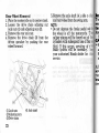
Rear Wheel Removal
1. Place the motorcycle on its center stand.
2. Loosen the drive chain adjustng nut
lock nuts (1) and adjusting nuts (2).
3. Removethe rear axle nut.
4. Remove the drive chain (3) from the
driven sprocket by pushing the rear
wheel forward.
5.Remove the axle shaft (4 ), side c
and rear wheel from the swing arm.
NOTE:
* Do not depress the brake pedal wh
the wheel is off the motorcycle. T
caliper pistons will be forced out of
cylinders with subsequentloss of bra
fluid. If this occurs, servicing of t
brake system will be necessary.
your authorized Honda dealer for
service.
h
lo
aen
frhe
ttrl
I
GAI
tY
c
b
d
Ani
ffit
r\ra
hral
i.et
(1)Lock nuts
(2)Adjusting nuts
(3)Drive chain
72
(4) Axle shaft
':iallation
-.
install the rear wheel, reverse the
.roval procedure.Torque the axle nut to
= specifiedtorque.
r1enut torque:
lO N'm (9,0 kg-m,65 lb{t}
.AUTION:
' \l hen installing
the wheel
r-arefully, f it the brake disc
between the brake pads to avoid
damaging the pads.
@
*
If a torque wrench was not used
for installation,
see your authorized Honda dealer as soon as
possible to verify proper assembly.
Improper assembly may lead to
loss of braking capacity.
-:er installing the wheel,apply the brake
- 'eral times and then check if the wheel
-:tes freely. Recheck the wheel if the
-.te drags or if the wheel doesnot rotate
.:ly.
73
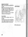
BRAKE PAD WEAR
(Refer to the maintenance precautions on
page50 ).
Brake pad wear dependsupon the severity
of usage, the type of riding, and road
conditions. (Generally, the pads will wear
faster on wet and dirty roads.)
Inspect the pads at each regular
maintenanceinterval (page45 ).
Front Brake
Check the wear indicator mark ( 1) on
eachpad.
If either pad is worn to the wear indicator
mark, replaceboth padsas a set. Seeyour
authorized Honda dealer for this service.
(FRONTBRAKE)
'rP,
$i
i)\
i\K
.\,\<q
(1)Wear indicator mark
74
i" ear Brake
- :-:ck the cutout (2 ) in eachpad.
- =:therpad is worn to the cutout, replace
r-r pads as a set. See your authorized
- :da dealerfor this service.
(REARBRAKE)
(2)
(2)Cutout
75
BATTERY
(Refer to the maintenanceprecautionson
page50).
If the motorcycle is operated with
insufficient battery electrolyte, sulfation
and battery plate damagewill occur.
If rapid loss of electrolyteis experienced,
or if your battery seems to be weak,
causing slow starting or other electrical
problems, see your authorized Honda
dealer.
* The battery gives off exPlosive
gases; keep sparks, flames, and
cigarettes away. Provide ade'
quate ventilation when charging
or using the battery in an en'
closed space.
76
* The battery contains sulfuric acid
(electrolyte). Contact with skin or
eyes may cause severe burns.
Wear protective clothing and a
face shield.
- If electrolyte gets on your skin'
flush with water.
- If electrolyte gets in your eYes,
flush with water for at least 15
minutes and call a physician
immediately.
* Electrolyte is poisonous.
- If swallowed, drink large quan'
tities of water or milk and fol'
low with milk of magnesia or
vegetable oil and call a PhYsi'
clan.
* KEEP OUT OF REACH OF CHIL.
DREN.
::Jerv
electrolyte:
--,e
battery (1) is behind the right side
;er. Removethe right side cover(page
-:eck the electrolyte level with the
* -:orcyclein an upright positionon level
- -'und. The electrolyte level must be
-.:ntained between the UPPER (2) and
, ,WER ( 3) level marks on the side of the
r:iefy.
,he electrolyte level is low, remove the
.:r caps.Carefully add distilled water to
,.er level mark, using a small syringe or
.=iic funnel.
3attery
-OWER level
CAUTION:
* When checking the battery
level or adding
electrolyte
distilled water, make sure the
breather tube is connected to the
battery breather outlet.
* Use only distilled
water in the
battery. Tap water wilf shorten
the service life of the battery.
* Filling the battery above the
UPPER LEVEL line may cause
to overf low,
the electrolyte
resulting in corrosion to engine or
wash
frame parts. Immediately
off any spilled electrolyte.
* The battery breather tube must
be routed as shown on the label.
Do not bend or twist the breather
tube. A bent or kinked breather
tube may pressurize the battery
and damage its case.
(2) UPPER level
(4) Battery breather tube
77
GAUTION:
* When the motorcycle
is to be
stored for an extended period of
time, remove the battery from the
motorcycle and charge it fully.
Then store it in a cool, dry place.
If the battery is to be left in the
motorcycle, disconnect the negative cable from the battery terminal.
Battery Removal:
1. Removethe right side cover (page33 ).
2. Disconnect the negative (-) terminal
lead ( 1 ) from the battery first, then
disconnectthe positive(+) terminal lead
(2).
3. Disconnectthe battery breather tube
(3 ).
4. Remove the battery holder ( ) bv
removingthe three bolts (5 ).
5. Pull out the battery box(0 ) and remove
the battery.
78
(1)Negative(-)terminal lead
(2)Positive(+) terminal lead
(3) Battery breather tube
(4) Battery holder
(5) Bolts
(6) Battery box
; T-SE REPLACEMENT
: .-er to the maintenance precautions on
-- ; e 5 0 ) .
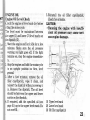
:= main fuse ( 1), locatedon the starter
: ..retic switch ( 2 ) below the seat , is 30
r: sparemain fuse (6) is locatednear the
;. box. The fuse box (4 ) is also located
- ..i- the seat.
When frequent fuse failure occurs, it
usually indicates a short circuit or an
overload in the electrical system. See your
authorized Honda dealer for repair.
GAUTION:
* Turn the ignition switch OFF
before checking or replacing
fuses to prevent accidental shortcircuiting.
To replacethe main fuse ( 1), removethe
right side cover (page33),disconnectthe
wire coupler( 3 ) and removethe old fuse.
Install a new fuse and reconnect the wire
coupler.
" r.t/
':
(1)
,lajn fuse
" re coupler
(2) Starter magrreticswitch
*,-@
(4) Fuse box
(5) Sparefuses
(6) Sparemain fuse
79
To replace fuses in the fuse box ( 4 ),
removethe the fuse box cover.
The spare fuses (5) are located in the
fuse box.
Pull the old fuse out of the clips. Push a
new fuse into the clips and install the fuse
box cover.
@
*
Never use a fuse with a different
rating from that specified.
Serious damage to the electrical
system or a fire may result,
causing a dangerous loss of lights
or engine power.
E
i
H
I
I
(7)
I
ffi
UU'
\(
(7) Blown fuse
80
]LLBREPLACEMENT
--=:erto the maintenanceprecautionson
..e50).
: eadlight/Position Light Bulb
1.Remove the screws (1) from the
headlightcase.
2. Gently pull the headlisht forward and
disconnectthe connectors(2).
@
,The
light bulb becomes very hot
while the light is ON, and remain
hot for a while after it is turned
rfFF. Be sure to let it cool down
before servicing.
:AUTION:
I\ear clean gloves while rePlacing
,he bulb.
Do not put finger Prints on the
bulb, as they may
leadlight
:Teate hot spots on the bulb and
;ause it to break.
ii you touch the bulb with Your
:are hands, clean it v/ith a cloth
alcohol to
:noistened with
lrevent its early failure.
I r-E:
:.= sure to turn the ignition switch OFF
- :-enreplacing the bulb.
(1) Screws
(2\ Connectors
81
3. Removethe seat rubber (3).
4. Remove the bulb (4) while pressing
down on the pin (5).
5. Install a new bulb in the reverse order
of removal.
NOTE:
* Do not use bulbs other than that
specified.
* After installing a new bulb, check that
the light operatesproperly.
S{
T
(3) Seat rubber
(4) Bulb
82
(5) Pin
-:op/Taillight
@
'
Bulb
The light bulb becomes very hot
rhile the light is ON, and remain
hot for a while after it is turned
rlFF. Be sure to let it cool down
D€fore servicing.
.AUTION:
i\-ear clean gloves while replacing
:he bulb.
" lt you touch the bulb with your
rare hands, clean it with a cloth
:noistened with
alcohol to
its early failure.
;revent
_- E :
-o sure to turn the ignition switch OFF
' :en replacingthe bulb.
1. Removethe two screws(1).
2. Removethe taillight lens (2).
(2)
(1) Screws
(2) Taillight lens
83
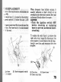
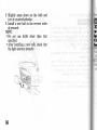
3. Slightly press down on the bulb and
turn it counterclockwise.
4. Install a new bulb in the reverse order
of removal.
NOTE:
* Do not use bulbs other than that
specified.
* After installing a new bulb, check that
the light operatesproperly.
a4
ft
rl
Lo
OT
bd
J:ont/Rear Turn Signal Bulb
@
1. Remove the three screws (1).
2. Remove the turn signal lens (2).
, The light bulb becomes very hot
rhile the light is ON, and remain
rot for a while after it is turned
,lFF. Be sure to let it cool down
r"efore servicing.
.I JTION:
'\'ear clean gloves while replacing
-ire
- E :bulb.
.
:; sure to turn the ignition switch OFF
, .en replacingthe bulb.
(1) Screws
(2) Turn signal lens
85
3. Remove the bulb (3) by pressing in and
turning counterclockwise.
4. Install a new bulb and check that the
light operatesproperly.
NOTE:
* Do not use bulbs other than that
specified.
* After installing a new hulb, check that
the lisht operatesproperly.
86
: LEANING
. :an your motorcycle regularly to
-.:ect the surface finishes and inspect
: Camage,wear, and oil or brake fluid
]AUTION:
High pressure water (or air) can
damage certain parts of the
notorcycle.
-:d spraying high pressure water
::cal in coin-operatedcar washes) at
r. :ollowingareas:
Instruments
;:ition Switch
--:.rburetors
Wheel Hubs
-::r.e
Muffler Outlets
-'rderChain
Seat
Under Fuel Tank
-:ndlebar Switches
.:ake MasterCylinder
--':er cleaning, rinse the motorcycle
:-rroughly with plenty of clean water.
:::ong detergent residue can corrode
I ;i- parts.
NOTE:
* Clean the plastic parts using a cloth or
sponge dampened with a solution of
mild detergent and water. Rub the
soiled area gently rinsing it frequently
with fresh water.
2. Dry the motorcycle, start the engine,
and let it run for several minutes.
3. Test the brakes before riding the
motorcycle.Severalapplicationsmay be
necessary to restore normal braking
perrormance.
4. Lubricate the drive chain immediately
after washing and drying the motorcycle.
* Braking efficiency may be temlrorarily impaired immediately after
washing the motorcycle. Anticipate longer stopping distance to
avoid a possible accident.
a7
Aluminum Wheel Maintenance
Aluminum corrodes when it comes in
contact with dust, mud, road salt, etc.
After riding, clean the wheels with a wet
spongeand mild detergent,then rinse well
with water and wipe dry with a clean
cloth.
CAUTIONT
* Do not use steel wool or a cleaner
containing abrasives or compounds to clean the wheels, as
they can cause damage.
* Do not ride over a curb or rub the
wheel against an obstacle, as
wheel damage may result.
--
:'t
-ri
SI
_
_
r
:
l
t,l
. l
88
:TORAGE GUIDE
: :ended storage, such as for winter,
--.lires that you take certain steps to
- : rce the effects of deterioration from
:-use of the motorcycle. In addition,
: l€SS?r] repairs should be made
: FORE storing the motorcycle;
-.:rwise,these repairs may be forgotten
:he time the motorcycle is removed
:r storage.
", ORAGE
-:1angethe engineoil and filter.
:ain the fuel tank and carburetorsinto
.- approvedpetrol container.Spray the
:side of the tank with an aerosolrustribiting oil.
: =installthe fuel fill cap on the tank.
-E:
"
storagewill last more than one month,
.:buretor draining is very important,
assure proper perlormance alter
-
_i a g e .
* Petrol is extremely
flammable
and is explosive under certain
Perform
this
conditions.
in a well-ventilated
operation
area with the engine stopped. Do
not smoke or allow flames or
sparks in the area where petrol is
drained or stored and where the
fuel tank is refueled.
3. Remove the spark plugs and pour a
tablespoon(15-20 cc) of clean engine
oil into each cylinder. Crank the engine
several times to distribute the oil, then
reinstall the spark plugs.
NOTE:
* When turning the engineover, turn the
ignition switch OFF, select second or
third (or hisher) gear, and push the
motorcycle forward to turn the rear
wheel.
89
4. Remove the battery. Store in an area
protected from freezing temperatures
and direct sunlight.
Slow charge the battery once a month.
5. Wash and dry the motorcycle. Wax all
painted surfaces. Coat chrome with
rustinhibiting oil.
6. Lubricate the drive chain (page64).
7. Inflate the tyres to their recommended
pressures. Place the motorcycle on
blocks to raise both tyres off the ground.
8. Cover the motorcycle(dont use plastic
or other coated materials) and store in
an unheated area, free of dampness
with a minimum of daily temperature
variation. Do not store the motorcycle
in direct sunlight.
90
REMOVAL FROM STORAGE
1. Uncover and cleanthe motorcycle.
Change the engine oil if more than 4
months have passed since the start of
storage.
2. Check the battery electrolyte level and
charge the battery as required. Install
the battery.
3. Drain any excessaerosolrust-inhibiting
oil from the fuel tank. Fill the fuel tank
with fresh petrol.
4. Perform all Pre-rideInspectionchecks
(page34 ). ,
Test ride the motorcycle at low speeds
in a saferiding area away from traffic.
>PECIFICATIONS
-,IMENSIONS
')verall length
)verall width
Jverall height
l\-heelbase
2,?A mm (87.4 in).. AR, I G, IIG,MG,SW
2 1 5 5 m m { 8 4 . 8i n ) " E , E D ,F , S P ,U
78O mm (30.7 in)
1,1(X)mm{43.3 in)
1,495 mm (58.9 in)
EIGHT
)ry weight
215.Oks{474.0 lbs}
. \PACITIES
::rgine oil After draining
After draining and
oil filter change
After disassembly
. iel tank
. :el reserve
:.ssenger CapaCity
laximum weight capacity
2.8 0 {3.0 USqt ,2.5 lmpqt)
3.O A |.3.2USqt,2.6 lmpqt)
3.8 0 (4.OUS qt ,3,3 lmp qt)
n.O A (5.28 US sal,4.4O lmp gal)
3.O 0 (O.79US gal, 0.66 lmp sal)
Operatorand one passenger
1 9 Ok g ( 4 1 9 l b s )
91
ENGINE
Bore and stroke
Compressionratio
Displacement
Spark plug
Standard
67 x 53 mm (2.64x 2.09 mm)
9 . 3 :1
747 cm3(45.6 cu-in)
D P R S E A - 9 ( N G Ko) r
X24EPR_ U9(NIPPONDENSO)
For extendedhigh speedriding DPR9EA-9(NGK)or
-U9(NIPPONDENSO}
X27EPR
FT
j
Spark plug gap
Idle speed
92
0.8-0.9 mm (0.03-0.04 in)
1 , 2 0 0 + 1 0 Om i n i ( r p m ).. E , F .I G , t r G , I I I G , E D , U
1 , 2 0 0 + 5 0m i n i ( r p m ) . .S W
{
[ :
I
|
= AND su SPENSI'N
^.-,?:,t
. rail
- vre size,front
rear
I arr" size,
,*t* TRANSMISSION
L' t:imary
I
|
reduction
:ar ratio, lst-
26"
91 mm (3.6 in)
120170R178V (Dur{-trI
1201702R17 IMICHELTO
150/70R17 69V (DUNLOPI
(MICHELNI
15r'/702R17
1.780
3.000
2.056
1.545
1.240
1.O74
2.667
I -,''^,,..r'.q'il'
I
93
ELECTRICAL
Battery
Generator
LIGHTS
Headlight
TaiUbrake light
Turn signal light
12V-14Ah
0.24 kW/5,O0Ominj(rpm)
Front
Rear
Instrument lights
Neutral indicator light
Turn signal indicator light
High beam indicator light
Low oil pressureindicator light
Sidestand indicator
FUSE
94
12V-60/55W
1 2 V - 5 1 2 1 Wx 2
12V-21W
12V-21W
1Al-3.4W x2
12V-1.7W
121t-1.7W
12V-1.7W
12\/ -1.7\N
l2\t-1.7W
3OA(Mainfuse)
10A,15A
IT
T
1r
tr
d
til
T't
h
\OISE CONTROL SYSTEM (AUSTRALIA ONLY)
- \MPERING WITH THE NOISE CONTROL SYSTEM IS PROHIBITED: Owners are
":rned that the law may prohibit : (a) The removal or rendering inoperative by any
-trson other than for purposesof maintenance,repair, or replacement, of any device or
: :m€nt of design incorporated into any new vehicle for the purposeof noise control prior
- its sale or delivery to the ultimate purchaser or while it is in use; and (b) the use of the
.ricle after such device or element of desig! has been removed or rendered inoperative
: any person.
95
-'v