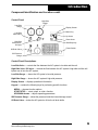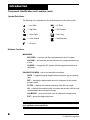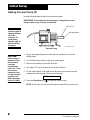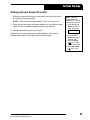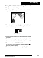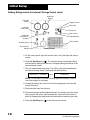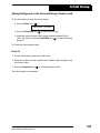
1
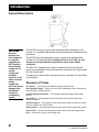
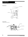
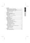
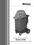
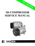
Owner’s Manual Manual del propietario Model AC375C Refrigerant Recovery, Recycle, and Recharge Unit Modelo AC375C Unidad de refrigerante, recuperación y reciclaje Model AC375C Recover, Recycle, and Recharge Unit for R-12 or R-134a Refrigerant Voltage: 220–230; 50–60 Hz SAFETY DEFINITIONS: Follow all WARNING, CAUTION, IMPORTANT, and NOTE messages in this manual. These messages are defined as follows: WARNING means you may risk serious personal injury or death; CAUTION means you may risk personal injury, property damage, or serious unit damage; IMPORTANT means you may risk unit damage; and NOTEs provide clarity and helpful tips. These safety messages cover situations ROBINAIR is aware of. ROBINAIR cannot know, evaluate, and advise you regarding all possible hazards. You must make sure all conditions and procedures do not jeopardize your personal safety. COPYRIGHT: No part of this manual may be reproduced, stored in a retrieval system, or transmitted in any form or by any means (electronic, mechanical, photocopy, recorded, or otherwise) without the prior written permission of ROBINAIR. DISCLAIMER: All information, illustrations, and specifications contained in this manual are based on the latest information available at the time of publication. The right is reserved to make changes at any time without obligation to notify any person or organization of such revisions or changes. ROBINAIR shall not be liable for errors contained herein or for incidental or consequential damages (including lost profits) in connection with the furnishing, performance, or use of this material. If necessary, obtain additional health and safety information from the appropriate government agencies, and the vehicle, refrigerant, and lubricant manufacturers. WARNINGS ALLOW ONLY QUALIFIED PERSONNEL TO OPERATE THE UNIT. Before operating the unit, read and follow the instructions and warnings in this manual. The operator must be familiar with air conditioning and refrigeration systems, refrigerants, and the dangers of pressurized components. If the operator cannot read these instructions, operating instructions and safety precautions must be read and discussed in the operator’s native language. PRESSURIZED TANK CONTAINS LIQUID REFRIGERANT. Do not recover or charge refrigerants into non-refillable containers; use only authorized refillable containers. ALL HOSES MAY CONTAIN LIQUID REFRIGERANT UNDER PRESSURE. Contact with refrigerant may cause personal injury. Wear protective equipment, including safety goggles. Disconnect hoses using extreme caution. DO NOT BREATHE REFRIGERANT AND LUBRICANT VAPOR OR MIST. Exposure may cause personal injury, especially to the eyes, nose, throat, and lungs. Use the unit in locations with mechanical ventilation that provides at least four air changes per hour. If accidental system discharge occurs, ventilate the work area before resuming service. AVOID USING AN EXTENSION CORD. An extension cord may overheat and cause fire. If you must use an extension cord, use the shortest possible cord with a minimum size of 14 AWG. TO REDUCE THE RISK OF FIRE, do not use the unit in the vicinity of spilled or open containers of gasoline or other flammable substances. DO NOT USE COMPRESSED AIR TO PRESSURE TEST OR LEAK TEST THE UNIT OR VEHICLE AIR CONDITIONING SYSTEM. Some mixtures of air and refrigerant are combustible at elevated pressures. These mixtures are potentially dangerous and may result in fire or explosion causing personal injury or property damage. USE THE UNIT WITH EITHER R-134a OR R-12 REFRIGERANT. The unit is designed for recovering, recycling, and recharging either R-134a or R-12 refrigerant. The user must dedicate the unit to only one type of refrigerant. Do not attempt to adapt the unit for another refrigerant. Do not mix refrigerant types through a system or in the same container; mixing of refrigerants will cause severe damage to the unit and the vehicle air conditioning system. HIGH VOLTAGE ELECTRICITY INSIDE THE UNIT HAS A RISK OF ELECTRICAL SHOCK. Exposure may cause personal injury. Disconnect the power before opening the back door or servicing the unit. Table of Contents Safety Precautions ....................................................... inside front cover Introduction ......................................................................................... 2 General Description ......................................................................................... 2 Glossary of Terms ............................................................................................ 2 Component Identification and Location ............................................................ 3 Unit Front View ......................................................................................... 3 Unit Side View ........................................................................................... 3 Unit Back View .......................................................................................... 4 Vacuum Pump .......................................................................................... 4 Control Panel ............................................................................................ 5 Symbol Definitions .................................................................................... 6 Software Functions ................................................................................... 6 Initial Setup .......................................................................................... 7 Unpacking the Accessory Kit ........................................................................... 7 Placing the Translation Decal .......................................................................... 7 Adding Vacuum Pump Oil ................................................................................ 8 Adding Refrigerant to the Internal Storage Vessel ......................................... 10 Drain Oil .................................................................................................. 13 Operation ............................................................................................ 14 Operating Guidelines ..................................................................................... 14 Recovering the A/C System Refrigerant ........................................................ 16 Draining the A/C System Oil .......................................................................... 18 Evacuating the A/C System ........................................................................... 19 Replenishing the A/C System Oil ................................................................... 20 Recharging the A/C System Refrigerant ........................................................ 21 Clear Hoses ............................................................................................. 22 Slow Charge ............................................................................................. 22 Maintenance ....................................................................................... 23 Adding Additional Refrigerant to the Internal Storage Vessel ........................ 23 Drain Oil .................................................................................................. 24 Changing the Vacuum Pump Oil .................................................................... 25 Resetting Oil Time .................................................................................. 26 Replacing the Filter-Drier ............................................................................... 27 Resetting the Filter-Drier Capacity .......................................................... 29 Checking for Leaks ........................................................................................ 30 Calibrating the Weight Scale .......................................................................... 31 Cleaning the Unit ............................................................................................ 31 Replacement Parts ............................................................................. 32 Limited Warranty .......................................................... inside back cover Recover/Recycle/Recharge Unit 1 Introduction General Description CAUTION:: Once the machine has been dedicated to a specific refrigerant, do NOT adapt the unit to another refrigerant. Do not mix refrigerants through a system or in the same container; mixing refrigerants will cause severe damage to the unit and the vehicle air conditioning system. The AC375C recovers, recycles, and recharges vehicle refrigerant in one hookup. It is compatible with existing service equipment and standard service procedures. The AC375C may be configured to recover, recycle, and recharge either R-134a or R-12 refrigerant. Once configured to R-12 or R-134a, the unit should be used only with the refrigerant for which it was initially configured. The AC375C is equipped with a power receptacle; the user provides the power cord, depending on the electrical power connection in the region where the unit is being used. Throughout this manual metric measurements are used with U.S. equivalents in parentheses. Glossary of Terms A/C System — The vehicle air conditioning system being serviced. Hose Storage Fittings — When not in use, the R-134a fittings can be connected to these fittings for storage purposes. Internal Storage Vessel (ISV) — The refillable refrigerant storage vessel inside the unit. Panel Valves — The high-side and low-side valves on the control panel, when described together. Service Couplers — The couplers on the service hoses used to connect the hoses to the A/C system or to a source tank. Service Hoses — The red and blue hoses used to connect the unit to the A/C system. Source Tank — A tank of new refrigerant used to refill the internal storage vessel. Unit — The recover, recycle, and recharge unit. 2 © 2006 SPX Corporation Introduction Component Identification and Location Control Panel Unit Front View Tool Tray Oil Injector Bottle Vacuum Pump Internal Storage Vessel Oil Drain Bottle ISV Weight Scale Unit Side View Hood Owner’s Manual Compartment Hose Storage Fittings (for R-134a dedicated units) Power Receptacle Source Tank Strap Source Tank Compartment INST0986 Recover/Recycle/Recharge Unit 3 Introduction Component Identification and Location contd. Unit Back View Circuit Breaker Filter-Drier Vacuum Pump (location shown on previous page) Oil Fill Port Oil Sight Glass Oil Drain Port 4 © 2006 SPX Corporation Introduction Component Identification and Location contd. Control Panel High-Side Gauge Low-Side Gauge Low-Side Panel Valve Display Screen Menu Key Up Arrow High-Side Panel Valve / Oil Inject Oil Drain Valve Down Arrow Start/Stop Key Power Switch ISV Pressure Gauge Control Panel Descriptions Low-Side Valve — controls the flow between the A/C system’s low side and the unit. High-Side Valve / Oil Inject — controls the flow between the A/C system’s high side and the unit / injects new oil into the A/C system. Low-Side Gauge — shows the A/C system’s low-side pressure. High-Side Gauge — shows the A/C system’s high-side pressure. Display Screen — displays operational information. Keypad — contains the following keys for performing specific functions: MENU — chooses function options. START/STOP — starts, stops, or exits a function. UP/DOWN Arrows — adjusts operating parameters. ISV Pressure Gauge — shows the pressure inside the internal storage vessel. Oil Drain Valve — drains the A/C system’s oil into the oil drain bottle. Recover/Recycle/Recharge Unit 5 Introduction Component Identification and Location contd. Symbol Definitions The following is an explanation of the symbols shown on the control panel: — Low Side — Oil Drain — High Side — ISV Pressure — Valve Open — Menu Key — Valve Closed — Start/Stop Key — Oil Inject Software Functions MAIN MENU : RECOVER — recovers and filters refrigerant from the A/C system. VACUUM — activates the vacuum sequence for a programmed amount of time. CHARGE — charges the A/C system with the programmed amount of refrigerant. DIAGNOSTICS MENU : use to view and edit unit settings. UNITS — toggles displayed weight between kilograms (kg) and pounds (lbs.). REF — displays the approximate amount of refrigerant in the internal storage vessel. FILTER — displays the remaining capacity of the filter by weight. OIL — displays the remaining time in minutes and seconds until the next recommended vacuum pump oil change. CALIBRATE— service technician uses to calibrate the weight scale. EXIT— leaves the diagnostics menu. CAUTION: To avoid damage to the unit, calibration must be performed by a qualified service technician. 6 © 2006 SPX Corporation Initial Setup WARNING This manual contains important procedures concerning the setup, operation, and maintenance of the unit. Read and follow all the warnings outlined at the beginning of this manual. Do not operate the unit until you have read and entirely understand the contents of this manual. If you do not understand any of the contents of this manual, notify your supervisor. If the operator cannot read these instructions, all instructions and safety precautions must be read and discussed in the operator’s native language. Unpacking the Accessory Kit Unpack the accessory kit from the bag and remove the plastic packaging. The accessory kit consists of the following: l l l l l R-134a couplers. Vacuum pump oil. Owner’s manual. Low-side tank adapter. Translation decal. Placing the Translation Decal (optional) The unit ships with a language chart on the control panel. An optional decal is also provided, which lists other languages. If desired, remove the backing from the translation decal, align it over the existing chart on the control panel, and press it in place. Recover/Recycle/Recharge Unit 7 Initial Setup Adding Vacuum Pump Oil Use the following steps to add oil to the vacuum pump. IMPORTANT: For maximum unit performance, change the vacuum pump oil after every 10 hours of operation. Oil Fill Port CAUTION: The vacuum pump is shipped without oil in the reservoir. To avoid pump damage, add oil before starting the pump. Oil Sight Glass INST0 983 FH.eps Vacuum Pump CAUTION: Avoid using an extension cord. An extension cord may overheat and cause fire. If you must use an extension cord, use the shortest possible cord with a minimum size of 14 AWG. 1. Plug a user supplied power cord into the unit and then into a correct voltage outlet. 2. Turn ON the power switch on the unit’s control panel. 3. Remove the plastic plug from the oil fill port. 4. Pour about 177 mL (6 ounces) of oil into the oil fill port. 5. On the control panel, verify both panel valves are open and the service couplers are disconnected. The screen will display: CLEAR 6. Press the Start/Stop key ( 02.00 ) to start the vacuum pump. NOTE: At this time, the unit automatically evacuates all air from the unit. 8 © 2006 SPX Corporation Initial Setup Adding Vacuum Pump Oil contd. 7. With the vacuum pump running, slowly add oil until the level rises to the center of the oil sight glass. NOTE: The pump holds approximately 237 mL (8 ounces) of oil. 8. When the vacuum pump countdown reaches zero, the vacuum pump stops, and the unit display changes to the recover function. 9. Replace the plastic plug in the oil fill port. After adding oil to the vacuum pump, add refrigerant to the internal storage vessel. Refer to the instructions on the next page. Recover/Recycle/Recharge Unit Note: The unit’s weight default is in kilograms. To change the default to pounds: 1. Press the Up and Down arrow keys at the same time. UNITS KG will be displayed. 2. Press the Up or Down arrow key to toggle to LBS. 3. Press the Menu ( ) key until the display reads EXIT. 4. Press Start/Stop ( ) key to exit. 9 Initial Setup Adding Refrigerant to the Internal Storage Vessel Add refrigerant to the internal storage vessel (ISV) after adding oil to the vacuum pump. After the initial refrigerant fill, refill the ISV as necessary. (Refer to Adding Additional Refrigerant to the ISV.) The AC375C is shipped as an R-12 refrigerant unit. Use the following steps to dedicate the unit to R-134a refrigerant and add refrigerant to the internal storage vessel. WARNING Wear safety goggles when working with refrigerant. All hoses may contain liquid refrigerant under pressure. Disconnect hoses using extreme caution. Read and follow all warnings at the beginning of this manual before operating the unit. CAUTION: Use only one type of refrigerant (either R-134a or R-12) in the unit. Do not mix refrigerant types through a system or in the same container; mixing of refrigerants will cause severe damage both to the unit and the vehicle air conditioning system. Do not attempt to adapt the unit for another refrigerant. R-134a High-Side Hose Storage Fitting R-134a Low-Side Hose Storage Fitting Source Tank Strap Source Tank Compartment INST0986 Unit Components - Side View 10 © 2006 SPX Corporation Initial Setup Adding Refrigerant to the Internal Storage Vessel contd. R-12 refrigerant users start with Step 3. 1. Connect the blue R-134a coupler to the blue hose and the red R-134a coupler to the red hose as shown. R-134a Coupler 2. Connect the low-side tank adapter (from the accessory kit) to the liquid valve on the refrigerant source tank. NOTE: If using a refillable source tank, connect the tank adapter to the vapor valve. R-134a Tank Adapter 3. Connect the service coupler of the low-side hose (blue) to the refrigerant source tank. 4. Open the valve on the source tank, and place the tank upside down in the source tank compartment. Secure the source tank in place by wrapping the strap around the tank and then fastening the strap. 5. The screen should display RECOVER XX.XXKG. If it does not, scroll through the functions, pressing the Menu key ( ) until RECOVER XX.XXKG is displayed. 6. Press the Arrow keys to adjust the recover weight to 7 kg (15 lbs.). Recover/Recycle/Recharge Unit 11 Initial Setup Adding Refrigerant to the Internal Storage Vessel contd. High-Side Gauge Low-Side Gauge Display Screen Menu Key Low-Side Panel Valve Up Arrow Down Arrow High-Side Panel Valve / Oil Inject Start/Stop Key Power Switch Oil Drain Valve ISV Pressure Gauge Control Panel 5. On the control panel, open the low-side valve; verify the high-side valve is closed. 6. Press the Start/Stop key ( ). The internal storage vessel begins filling, and the screen displays the amount of refrigerant being transferred to the internal storage vessel. 7. The unit automatically stops when 7 kg (15 lbs.) has been transferred to the internal storage vessel. The display will flash between: RECOVER XX.XXKG and DRAIN OIL NOTE: Do not drain oil until the following steps are complete. Drain oil instructions begin on next page. 8. Unstrap the source tank, remove it from its compartment, and close the source tank valve. 9. Disconnect the hose from the tank. 10. Cap the source tank with its original tank cap. For storage, place the source tank upright in the source tank compartment. Secure the source tank in place by wrapping the strap around the tank and then fastening the strap. 11. Press the Start/Stop key ( 12 ) to exit the recover function. © 2006 SPX Corporation Initial Setup Adding Refrigerant to the Internal Storage Vessel contd. 12. Do the following to clear the service hoses: a. Press the Menu key ( ) to: RECOVER b. Press the Start/Stop key ( XX.XXKG ) to start hose clearing. c. Watch the low-side gauge. When gauge pressure reaches 34 kPa (10 in. Hg) vacuum, press the Start/Stop key ( ) to stop the clearing process. 13. Close the low-side panel valve. Drain Oil 1. On the control panel, open the oil drain valve. 2. Watch the oil drain into the oil drain bottle. When oil stops draining, close the oil drain valve. 3. Press the Start/Stop key ( ) to exit the recover function. The initial setup is now complete. Recover/Recycle/Recharge Unit 13 Operation WARNING This manual contains important procedures concerning the setup, operation, and maintenance of the unit. Read and follow all warnings at the beginning of this manual. Do not operate the unit until you have read and entirely understand the contents of this manual. If you do not understand any of the contents of this manual, notify your supervisor. If the operator cannot read these instructions, all instructions and safety precautions must be read and discussed in the operator’s native language. Operating Guidelines For best results when operating the unit, use the following guidelines along with the operation instructions contained in this manual. CAUTION: Using the recovery compressor in vacuum for an extended period of time could damage the compressor. 14 l The compressor pulls the A/C system to a partial vacuum only. Use the vacuum function for a minimum of 15 minutes to remove moisture from the A/C system. Refer to Evacuating the A/C System in the “Operation” section of this manual. l The unit includes a 71 l/m (3 cfm) high vacuum pump for fast, thorough evacuation. Change the vacuum pump oil after every 10 hours of vacuum pump use. The unit displays a CHANGE OIL message as a reminder. Refer to Changing the Vacuum Pump Oil in the “Maintenance” section of this manual. l The unit is equipped with a circuit breaker button, located on the back of the unit. If the circuit breaker trips, the unit will not function correctly and will lose all power. If necessary, press the circuit breaker button to reset the unit. l This unit should be operated between the ambient temperatures of 11–49° C (50–120° F). At temperatures exceeding 40° C (104° F), wait 10 minutes between recovery jobs. l Follow the SAE-J2211 recommended service procedure for the containment of R-134a refrigerant, or SAE-J1989 for R-12 refrigerant. l During normal use, periodically inspect the unit for leaks. At a minimum, inspect the unit every three months. Refer to Checking for Leaks in the “Maintenance” section of this manual. © 2006 SPX Corporation Operation Operating Guidelines contd. l During operation, any of the following messages may appear on the display screen. If a message appears, immediately take the appropriate action. CHANGE FILTER — This message appears after every 68.0 kg (150 lbs.) of refrigerant has been recovered, indicating that the filter-drier needs to be replaced. Refer to Replacing the Filter-Drier in the “Maintenance” section of this manual. NOTE: To avoid service delays, keep extra filterdriers on hand. CHANGE OIL — This message appears after every 10 hours of vacuum pump use. Refer to Changing the Vacuum Pump Oil in the “Maintenance” section of this manual. DRAIN OIL — This message appears after recovering refrigerant from an A/C system. For more information, refer to Draining the A/C System Oil in this “Operation” section of this manual. HIGH PRESSURE — This message appears if the internal storage vessel’s pressure rises to 25 bar (365 psig) or higher. Let the unit cool down for 30 minutes. Then press the Menu key ( ) and the Up arrow key to clear the message from the display screen. If the message does not clear, contact a manufacturer-authorized service technician. OVERLOAD — This message appears if the weight of the internal storage vessel reaches 21.3 kg (47 lbs.), or if the unit’s weight scale is damaged, disconnected, or out of calibration. Immediately remove refrigerant from the internal storage vessel. Then press the Menu key ( ) and the Up arrow key to clear the message from the display screen. If the message does not clear, contact a manufacturer authorized service technician. PRESSURE EXISTS — This message appears if there is pressure in the hoses when the vacuum cycle is started, and is designed to protect the vacuum pump from damage due to over pressurization. If this happens, you must recover before the vacuum operation is started. SLOW CHARGE — This message appears if the unit cannot charge .05 lbs. in 30 seconds. It may be necessary to use the vehicle to pull the refrigerant in. Refer to the Slow Charge procedure in this “Operation” section of this manual. Recover/Recycle/Recharge Unit 15 Operation Recovering the A/C System Refrigerant WARNING Wear safety goggles when working with refrigerant. All hoses may contain liquid refrigerant under pressure. Disconnect hoses using extreme caution. Read and follow all warnings at the beginning of this manual before operating the unit. Do not overfill the internal storage vessel. Overfilling may cause explosion and serious personal injury or death. If the message OVERLOAD appears in the display screen, the internal storage vessel is too full — remove refrigerant. If the message HIGH PRESSURE appears in the display screen, let the unit cool down. If the message does not clear, call an authorized service technician. Do not recover or charge refrigerants into nonrefillable containers; use only authorized refillable refrigerant containers. Do not overfill refrigerant containers. Overfilling may cause explosion and serious personal injury or death. The unit is designed to recover, recycle, and recharge either R-134a or R-12 refrigerant! The user must dedicate the unit to only one type of refrigerant. Do not attempt to adapt the unit for another refrigerant. Do not mix refrigerant types through a system or in the same container; mixing of refrigerants will cause severe damage to the unit and the vehicle air conditioning system. Use the following steps to recover refrigerant from the vehicle’s A/C system. 1. Plug the user supplied power cord into a correct voltage outlet, and turn the unit ON. Note: It is normal to hear air purge from the tank every time the unit is powered. 2. Connect the service hoses to the A/C system. IMPORTANT: Connect the red service hose to the A/C system’s high side; connect the blue service hose to the low side. High-Side Gauge Low-Side Gauge Display Screen Menu Key Low-Side Panel Valve Up Arrow Down Arrow High-Side Panel Valve / Oil Inject Start/Stop Key Power Switch Oil Drain Valve ISV Pressure Gauge Control Panel 16 © 2006 SPX Corporation Operation Recovering the A/C System Refrigerant contd. 3. On the control panel, open both panel valves. 4. Press the Menu key ( ) until RECOVER X.XX KG is displayed. (X.XX is the amount of refrigerant capacity remaining in the internal storage vessel [ISV].) Press the Start/Stop key ( ) to begin the recovery operation. Once recovery begins, RECOVER X.XXKG changes from the amount in the ISV to the amount being recovered. Note: • Verify there is enough room in the ISV by comparing the amount of refrigerant in the A/C system to the amount on the display screen. The amount in the A/C system should not be greater than the amount initially displayed. If the amount is greater, charge some of the refrigerant from the ISV into another refillable refrigerant tank making enough room available. • The compressor pulls the A/C system to a partial vacuum only. You must use the unit’s vacuum (evacuate) cycle to remove moisture from the A/C system. 5. Watch the low-side gauge. When the pressure gauge reaches 34 kPa (10 in. Hg) vacuum, press the Start/Stop key ( ). The display screen will indicate how much refrigerant has been recovered. The display screen toggles between: RECOVER XX.XXKG and DRAIN OIL CAUTION: Using the recovery compressor in vacuum for an extended period of time could damage the compressor. NOTE: Drain oil after the recovery is complete; refer to next page for draining the oil. 6. Close both panel valves. 7. Wait two minutes and then check the low-side gauge for a rise in pressure to above zero. If there is a rise in pressure, repeat Steps 4 through 8 as needed until the pressure holds below zero for two minutes. NOTE: If the pressure does not drop to 34 kPa (10 in. Hg) vacuum, or does not hold at 34 kPa (10 in. Hg) vacuum for at least two minutes, there was freezing in the A/C system during recovery, or the A/C system requires repair. Repeat recovery or repair the A/C system as necessary. 8. Press the Start/Stop key ( ) to exit the recover function. After recovering all refrigerant from the A/C system, drain the A/C system oil. Refer to the instructions on the next page. Recover/Recycle/Recharge Unit 17 Operation Draining the A/C System Oil After recovering the refrigerant from the A/C system, use the following steps to drain the A/C system oil into the unit’s oil drain bottle. Oil Drain Valve Oil Drain Bottle Oil Drain Bottle Location 1. Verify the oil drain bottle is empty. Remove, empty, and replace the oil drain bottle if necessary. NOTE: Dispose of oil according to current local regulations. 2. On the control panel, open the Oil Drain valve. Watch the oil drain into the oil drain bottle. 3. When the oil stops draining, close the Oil Drain valve. 4. Check the oil drain bottle, and record the amount of oil removed. This is the amount of oil that must be added to the A/C system after evacuating the A/C system. Refer to Replenishing the A/C System Oil in the “Operation” section of this manual. 5. Remove, empty, and replace the oil drain bottle. After draining the oil, evacuate the A/C system. Refer to the instructions on the next page. 18 © 2006 SPX Corporation Operation Evacuating the A/C System After recovering all refrigerant from the A/C system, draining the oil from the system, and making repairs to the A/C system, use the following steps to evac uate (VACUUM) the A/C system. WARNING Wear safety goggles when working with refrigerant. All hoses may contain liquid refrigerant under pressure. Disconnect hoses using extreme caution. Read and follow all warnings at the beginning of this manual before operating the unit. 1. Verify the power cord is plugged into a correct voltage outlet, and the service hoses are connected to the A/C system. IMPORTANT: Connect the red service hose to the A/C system’s high side; connect the blue service hose to the low side. 2. On the control panel, turn the unit on, and open both panel valves. 3. Press the Menu key ( ) until the VACUUM screen displays. Press the Arrow keys to set the amount of time desired for the vacuum. Fifteen minutes is recommended, but the time may vary depending on environ mental conditions. VACUUM 15:00 NOTE: The display screen shows the time as mm:ss; where mm represents minutes and ss represents seconds. Setting vacuum time to 0 (zero) will result in continuous vacuum pump operation. To exit the vacuum function, press the Start/Stop key ( ). 4. Press the Start/Stop key ( ) to begin the vacuum operation. Watch the vacuum time on the display — the display counts down the amount of time it will take to evacuate the A/C system. Caution: If the display shows PRESSURE EXISTS, there is pressure in the hoses which may damage the vacuum pump. You must perform a recovery operation before starting the vacuum operation. VACUUM 00.00 5. When the evacuation is complete, the unit automatically shuts off, and IN JECT OIL displays on the screen. 6. Close both panel valves on the control panel. 7. Note the pressure on the low-side gauge, and then wait five minutes. 8. Check the low-side gauge for a rise in pressure. If pressure remains sta ble, evacuation is complete. If there is a rise in pressure, the A/C system may need further repairs, or the evacuation may need to be repeated. Recover/Recycle/Recharge Unit 19 Operation Replenishing the A/C System Oil Before recharging the A/C system, replenish the A/C system oil. Add only the amount of oil that was removed during recovery. If no oil was removed, do not add any oil. NOTE: • Consult the A/C system manufacturer for correct oil replacement procedures and oil specifications. • Replacing A/C system components may require adding more oil. Consult the component manufacturer for recommendations. 1. Refer to amount of oil that was removed during recovery. (See Step 4 on page 18.) 2. Fill oil injector bottle with new oil: • Add 30–60 mL (1–2 ounces) more oil than was recovered in Step 4 on page 18. • Add any additional oil required by A/C component change. 3. Note the level of new oil in the bottle. 4. Turn the high-side valve to the Oil Inject position ( ) until the system is replenished with the desired amount of oil. NOTE: To avoid getting air into the A/C system, do not remove all the oil from the oil inject bottle. 5. Close the high-side valve. 6. Press the Start/Stop key ( ) to exit the vacuum function. To ensure replenishment of oil into the A/C system, immediately recharge the A/C system. Refer to instructions on the next page. 20 © 2006 SPX Corporation Operation Recharging the A/C System Refrigerant WARNING Wear safety goggles when working with refrigerant. All hoses may contain liquid refrigerant under pressure. Disconnect hoses using extreme caution. Read and follow all warnings at the beginning of this manual before operating the unit. After evacuating the A/C system and replenishing the A/C system oil as necessary, use the following steps to recharge the A/C system’s refrigerant. NOTE: For maximum unit performance during recharging, verify the refrigerant level in the source tank is at least 1.4 kg (3 lbs.) more than the amount required for recharging the vehicle being serviced. 1. Refer to the A/C system manufacturer’s service manual to determine the required amount of refrigerant to recharge. 2. Verify the unit’s power cord is plugged into a correct voltage outlet and that the service hoses are connected to the A/C system. IMPORTANT: Connect the red service hose to the A/C system’s high side; connect the blue service hose to the low side. 3. On the control panel, turn the unit ON. Press the Menu key ( ) until CHARGE XX.XX displays (XX.XX refers to the charge weight). Use the Arrow keys to program how much to charge. Refer to the vehicle manufacturer’s specifications for the amount to charge. CAUTION: R-134a systems have special fittings to avoid cross contamination with R-12 systems. Do not attempt to adapt the unit for another refrigerant — system failure will result! 4. Open the appropriate panel valve(s) according to the A/C system manufacturer’s specifications. 5. Press the Start/Stop key ( ) to begin charging. The screen displays the amount of refrigerant being charged. 6. Watch the display screen. When the required amount appears, the screen will toggle between CHARGE COMPLETE and the amount that has been charged. CHARGE COMPLETE and CHARGE XX.XX In some cases, the unit may not be able to charge the full amount, and will display SLOW CHARGE. Skip to the Slow Charge Procedure on the next page. Recover/Recycle/Recharge Unit 21 Operation Recharging the A/C System Refrigerant contd. Clear Hoses CAUTION: Before starting the vehicle’s engine, verify the vehicle is in PARK, or NEUTRAL, with the emergency brake ON. Never run a vehicle without adequate ventilation in the work area. After the charge is complete, or after using the unit to diagnose an A/C system, clear remaining refrigerant from the hoses to ensure a more accurate charge. Follow this procedure to ensure all the liquid refrigerant trapped in the service hoses is transferred to the vehicle A/C system. 1. Disconnect the high-side service coupler from the vehicle. 2. Open both panel valves 3. Place the vehicle gear selector in park or neutral with the emergency brake ON. 4. Start the vehicle. Set the A/C system to its maximum setting. 5. The unit will charge out of the low-side inlet only, allowing the vehicle’s compressor to pull the refrigerant into the A/C system. 6. Open and disconnect the low-side coupler from the vehicle after the highand low-side pressure gauges are at their lowest pressure reading. 7. Turn off the vehicle engine. 8. Close the panel valves. 9. Press the Start/Stop key ( Slow Charge Procedure ) to exit the charge function. SLOW CHARGE In some cases, the unit may not be able to charge the full amount. If the unit cannot charge .05 lbs. in 30 seconds, the display shows SLOW CHARGE. If this occurs, follow this procedure to pull the refrigerant in using the vehicle. 1. Disconnect the high-side service coupler from the vehicle. 2. Open both panel valves. 3. Place the vehicle gear selector in park, or neutral, with the emergency brake ON. 4. Start the vehicle. Set the A/C system to its maximum setting. 5. The unit will charge out of the low-side inlet only, allowing the vehicle’s compressor to pull the refrigerant into the A/C system. 6. Open and disconnect the low-side coupler from the A/C system when the high and low pressure gauges are at their lowest reading. 7. When the required amount has been charged, the display shows CHARGE COMPLETE. Close both panel valves and disconnect the unit from the vehicle. 8. Close the panel valves. 9. Press the Start/Stop key ( 22 ) to exit the charge function. © 2006 SPX Corporation Maintenance Adding Additional Refrigerant to the Internal Vessel Periodically, the internal storage vessel (ISV) will require additional refrigerant. Use the following steps to add refrigerant to the ISV. 1. Connect the service coupler of the low-side hose (blue) to the refrigerant source tank. NOTE: If using a refillable source tank, connect to the vapor valve. R-134a tanks require the tank adapter (illustrated on page 11) to be used on the source tank. 2. Open the valve on the source tank, place the tank upside down in the source tank compartment, and secure the strap around the tank. 3. Press the Menu key ( ) until RECOVER XX.XXKG (LBS) is displayed. (XX.XX is the amount of refrigerant capacity remaining in the ISV.) 4. Press the Arrow keys to adjust to the desired recover weight. Note: Although the display shows the refrigerant capacity remaining in the ISV, the ISV should not be filled to this level. At least 4 kg (9 lbs.) of refrigerant capacity should be available in the ISV after filling to allow space for the next A/C recovery. Therefore, adjust the unit to fill the ISV to a level at least 4 kg (9 lbs.) less than what the display shows for remaining refrigerant capacity. 5. On the control panel, open the low-side valve; verify the high-side valve is closed. 6. Press the Start/Stop key ( ). The ISV begins filling, and the screen displays the amount of refrigerant being transferred to the ISV. 7. The unit automatically stops when the desired amount has been transferred to the ISV. The display will flash between: RECOVER XX.XXKG and DRAIN OIL NOTE: Drain oil after the internal storage vessel is filled. 8. Unstrap the source tank, remove it from its compartment, and close the source tank valve. 9. Disconnect the hose from the tank. 10. Cap the source tank with its original tank cap. For storage, place the source tank upright in the source tank compartment, and secure the source tank strap around the tank. 11. Press the Start/Stop key ( Recover/Recycle/Recharge Unit ) to exit the recover function. 23 Maintenance Adding Additional Refrigerant to the Internal Vessel contd. 12. Do the following to clear the service hoses: a. Press Menu key ( RECOVER ) to: XX.XXKG b. Press Start/Stop key ( ) to start hose clearing. c. Watch the low-side gauge. When gauge pressure reaches 34 kPa (10 in. Hg) vacuum, press the Start/Stop key ( ) to stop the clearing process. 13. Close the low-side panel valve. Drain Oil 1. On the control panel, open the oil drain valve. 2. Watch the oil drain into the oil drain bottle. When oil stops draining, close the oil drain valve. 3. Press the Start/Stop key ( 24 ) to exit the recover function. © 2006 SPX Corporation Maintenance Changing the Vacuum Pump Oil For maximum unit performance, change the vacuum pump oil after every 10 hours of operation. The unit keeps track of vacuum pump running time and notifies the user on the display screen when it is time to change oil. For optimum performance, use only Robinair Premium High Vacuum Oil. Use the following steps to change the vacuum pump oil. Oil Fill Port Oil Drain Port INST0983 FH.eps Vacuum Pump 1. Remove the cap from the oil drain port, and drain the oil into a suitable container for disposal. The container must be 474 mL (16 oz.) or larger. NOTE: Dispose of oil according to current local area regulations. 2. Replace the cap on the oil drain port. 3. Remove oil fill cap. 4. Add 177 mL (6 ounces) of oil. 5. Verify panel gauges read less than 0. 6. Press Menu key ( Stop key ( ). ) until screen displays VACUUM XX.XX. Press Start/ 7. With the vacuum pump running, slowly add oil until the level rises to the center of the oil sight glass. NOTE: The pump holds approximately 237 mL (8 ounces) of oil. 8. Press Start/Stop key ( ). 9. Replace cap. 10. Press Start/Stop key ( ) to exit vacuum. After changing the vacuum pump oil, reset oil time. Recover/Recycle/Recharge Unit 25 Maintenance Resetting Oil Time Every time the vacuum pump oil is changed, the vacuum pump oil timer should be reset. Use the following steps to reset the oil timer. 1. Press and hold the Up and Down arrows until the display shows UNITS KG (LBS). 2. Press Menu key ( ) until screen displays OIL XXX (XXX = minutes). 3. Press and hold the Up and Down arrows until the screen displays OIL 600 (minutes). 4. Press the Menu key ( ) until EXIT displays. 5. Press the Start/Stop key ( 26 ) to exit. © 2006 SPX Corporation Maintenance Replacing the Filter-Drier The filter-drier inside the unit removes acid, particulates, and moisture from refrigerant during the recovery function. To provide adequate contaminant and moisture removal, the filter-drier must be replaced after every 68 kg (150 lbs.) of refrigerant recovered. The following will appear in the display: CHANGE FILTER Use the following steps to replace the filter-drier. NOTE: For maximum unit performance, use only SPX/ROBINAIR filter-driers. To avoid service delays, keep extra filter-driers on hand. Refer to the Replacement Parts section of this manual. 1. Plug the power cord into a correct voltage outlet. 2. Verify the service hoses are NOT connected to a vehicle. High-Side Gauge Low-Side Gauge Display Screen Menu Key Low-Side Panel Valve Up Arrow Down Arrow High-Side Panel Valve / Oil Inject Start/Stop Key Power Switch Oil Drain Valve ISV Pressure Gauge Control Panel 3. On the control panel, open both panel valves. 4. Press the Menu key ( ) until RECOVER XX.XX displays on the screen. 5. Press the Start/Stop key ( ). 6. Watch the low-side gauge. When the gauge pressure reaches 34 kPa (10 in. Hg) vacuum, close both panel valves. 7. Press the Start/Stop key ( ). 8. Remove the power cord from the outlet. Recover/Recycle/Recharge Unit 27 Maintenance Replacing the Filter-Drier contd. WARNING High voltage electricity inside the unit has a risk of electrical shock. Disconnect the power before opening the back door or servicing the unit. 9. Open the back door of the unit’s protective covering by turning the two screws 1/4 turn counterclockwise. Filter-Drier Filter-Drier Location 10. Remove the strap, and disconnect the fittings from the filter-drier. NOTE: Dispose of the filter-drier according to current local area regulations. # FLOW 11. Install the new filter-drier with the FLOW direction arrow pointing down, tighten fittings, and secure with the strap. 12. Close and lock the back door of the unit’s plastic covering by turning the two screws 1/4 turn clockwise. After replacing the filter-drier, reset the filter-drier capacity. Refer to the instructions on the next page. 28 © 2006 SPX Corporation Maintenance Resetting the Filter-Drier Capacity The unit keeps track of the filter-drier’s remaining capacity. As the unit filters refrigerant, the remaining capacity decreases from 68 kg (150 lbs.) to zero. When the capacity reaches zero, the unit will display: CHANGE FILTER Use the following steps to reset the filter-drier’s capacity. 1. Plug the power cord into a correct voltage outlet. 2. Press the Arrow keys simultaneously until UNITS KG (LBS) appears on the display. 3. Press the Menu key ( ) until FILTER XXX appears on the display. 4. Press the Arrow keys simultaneously until FILTER 68KG (150 LBS) appears on the display. 5. Press the Menu key ( ) until EXIT displays. 6. Press the Start/Stop key ( ) to exit the diagnostics function. The unit is now ready to begin counting down for the new filter-drier. Recover/Recycle/Recharge Unit 29 Maintenance Checking for Leaks Over time, fittings can loosen as the unit is used and moved. During normal use, inspect the unit for leaks a minimum of every three months (or as specified by current local laws). Use the following steps to check the unit for leaks. NOTE: The manufacturer does not reimburse for lost refrigerant. 1. Remove the power cord from the outlet. WARNING High voltage electricity inside the unit has a risk of electrical shock. Disconnect the power before opening the back door or servicing the unit. 2. Remove the four screws that secure the hood. 3. Remove the hood. 4. Open the back door of the unit’s protective covering by turning the two screws 1/4 turn counterclockwise, and lift the door off the unit. 5. Remove the five screws that secure the front section of the unit’s protective covering, and remove the covering. 6. Use a leak detector to trace all lines and check all connections for refrigerant leaks. Tighten any fittings or connections if a leak is indicated. WARNING DO NOT use compressed air to pressure test or leak test the unit. Some mixtures of air and refrigerant are combustible at elevated pressures. These mixtures are potentially dangerous and may result in fire or explosion. 7. Replace the unit’s protective covering as follows: a. Replace the front section, and replace the five screws that secure the covering. b. Replace, close, and lock the back door by turning the two screws 1/4 turn clockwise. c. Replace the hood, and replace the four screws that secure the hood. 30 © 2006 SPX Corporation Maintenance WARNING This manual contains important procedures concerning the setup, operation, and maintenance of the unit. Read and follow all warnings at the beginning of this manual. Do not operate the unit until you have read and entirely understand the contents of this manual. If you do not understand any of the contents of this manual, notify your supervisor. If the operator cannot read these instructions, all instructions and safety precautions must be read and discussed in the operator’s native language. Calibrating the Weight Scale The unit’s weight scale is calibrated at the factory and requires no further calibration. NOTE: If the message OVERLOAD appears on the display screen on the control panel, the weight of the internal storage vessel is too high, or the unit’s weight scale is damaged, disconnected, or out of calibration. Call a qualified service technician. Cleaning the Unit On a regular basis, wipe off the unit with a clean cloth to remove grease, dust, or other dirt. Recover/Recycle/Recharge Unit 31 Replacement Parts The following is a list of replacement parts and accessories for the unit. For ordering information, use the technical support telephone number listed on the back cover of this manual. 32 Part No. Part Name 13204 Premium High Vacuum Pump Oil – Case of 4 Gallons 13203 Premium High Vacuum Pump Oil – Case of 12 Quarts 13201 Premium High Vacuum Pump Oil – Case of 12 Pints 535594 Low-side Service Coupler 535595 High-Side Service Coupler 534717 Filter-Drier 768220 Blue Service Hose 768320 Red Service Hose © 2006 SPX Corporation Limited Warranty Robinair Limited Warranty Statement Rev. November 1, 2005 Declaración de garantía limitada Robinair Revisión del 1 de noviembre de 2005 This product is warranted to be free from defects in workmanship, materials, and components for a period of one year from date of purchase. All parts and labor required to repair defective products covered under the warranty will be at no charge. The following restrictions apply: 1. The limited warranty applies to the original purchaser only. 2. The warranty applies to the product in normal usage situations only, as described in the Operating Manual. The product must be serviced and maintained as specified. 3. If the product fails, it will be repaired or replaced at the option of the manufacturer. 4. Transportation charges for warranty service will be reimbursed by the factory upon verification of the warranty claim and submission of a freight bill for normal ground service. Approval from the manufacturer must be obtained prior to shipping to an authorized service center. 5. Warranty service claims are subject to authorized inspection for product defect(s). 6. The manufacturer shall not be responsible for any additional costs associated with a product failure including, but not limited to, loss of work time, loss of refrigerant, cross-contamination of refrigerant, and unauthorized shipping and/or labor charges. 7. All warranty service claims must be made within the specified warranty period. Proof-of-purchase date must be supplied to the manufacturer. 8. Use of recovery/recycling equipment with unauthorized refrigerants or sealants will void warranty. • Authorized refrigerants are listed on the equipment or are available through the Technical Service Department. • The manufacturer prohibits the use of the recovery/ recycling equipment on air conditioning (A/C) systems containing leak sealants, either of a sealswelling or aerobic nature. Se garantiza que este producto no posee defectos de mano de obra, materiales y componentes por el período de un año a partir de la fecha de compra. Todas las partes y mano de obra requerida para reparar los productos con defecto cubiertos bajo la garantía no tendrán costo. Aplican las siguientes restricciones: 1. La garantía limitada aplica al comprador original únicamente. 2. La garantía aplica al producto en situaciones de uso normal únicamente, como lo indica el Manual de funcionamiento. Al producto se le debe dar servicio y mantenimiento como se especifica. 3. Si falla el producto, se debe reparar o reemplazar a discreción del fabricante. 4. Los cargos de transporte de servicio de garantía serán reembolsados por la fábrica al verificar el reclamo de garantía y presentar una boleta de flete por servicio terrestre regular. Se debe obtener la aprobación del fabricante antes de hacer el envío a un centro de servicio autorizado. 5. Los reclamos de servicio de garantía están sujetos a inspección de defectos del producto. 6. El fabricante no será responsable de los costos adicionales relacionados con fallas en el producto, que incluyen pero no se limitan a, tiempo improductivo, pérdida de refrigerante, contaminación de refrigerante y envío no autorizado o cargos por mano de obra. 7. Todo reclamo de servicio de garantía se debe hacer dentro del período de garantía establecido. Se debe proporcionar la fecha de la prueba de compra al fabricante. 8. El uso de equipo de recuperación/reciclaje con refrigerantes o selladores no autorizados anula la garantía. • Los refrigerantes autorizados se indican en el equipo o están disponibles a través del Departamento de servicio técnico. • El fabricante prohíbe el uso de equipo de recuperación/reciclaje en sistemas de aire acondicionado (A/C) con fugas de sellador, ya sea porque un sello se infla o es de naturaleza aeróbica. This Limited Warranty does not apply if: • The product, or product part, is broken by accident. • The product is misused, tampered with, or modified. • The product is used for recovering or recycling any substance other than the specified refrigerant type. This includes, but is not limited to, materials and chemicals used to seal leaks in A/C systems. Esta garantía limitada NO aplica si: • El producto, o parte de éste, se rompe accidentalmente. • El producto se usa incorrectamente, se adultera o modifica. • El producto se usa para recuperar o reciclar cualquier sustancia que sea diferente al tipo de refrigerante establecido. Esto incluye, pero no se limita a materiales y productos químicos utilizados para sellar fugas en sistemas de A/C. Call our International Customer Service Line at 1- 507- 455-7223 or email our Technical Support at [email protected] % To help us serve you better, be prepared to provide the model number, serial number, and date of purchase of your unit. To validate your warranty, complete the warranty card included with the unit, and return it within ten days from the purchase date. If your unit needs replacement parts, please contact your local distributor. If your unit needs repairs, you may locate service centers at www.robinair.com or by calling International Customer Service. Llame a nuestra línea internacional de servicio al cliente al 1- 507- 455-7223 o mándenos un correo electrónico a nuestro Servicio Técnico a [email protected] Para ayudarnos a servirle mejor, esté preparado para proporcionarnos el número se servicio, el número de serie y la fecha de compra de su unidad. Para validar su garantía, complete la tarjeta de garantía incluida con la unidad y regrésela dentro de los diez días posteriores a partir de la fecha de compra. Si la unidad necesita partes de reemplazo, por favor contacte a su distribuidor local. Si la unidad necesita reparaciones, usted puede localizar centros de servicio en www.robinair. com o al llamar al Servicio internacional al cliente. The unit’s weight scale provides a means for metering the amount of refrigerant needed for optimum air conditioning system performance as recommended by OEM manufacturers. Do not use the unit to sell refrigerant by weight, because this may not be permitted by certain local jurisdictions. La escala de peso de la unidad proporciona un medio para medir la cantidad de refrigerante que se necesita para el rendimiento óptimo del sistema de aire acondicionado, tal como lo recomiendan los fabricantes OEM. No use la unidad para vender refrigerante por peso, porque esto puede no estar permitido por ciertas jurisdicciones locales. Due to ongoing product improvements, we reserve the right to change design, specifications, and materials without notice. Debido a las constantes mejoras del producto, nos reservamos el derecho de cambiar diseño, especificaciones y materiales sin aviso. 655 Eisenhower Drive Owatonna, MN 55060-0995 USA Technical Services: 1-800-822-5561 Fax: 1-866-259-1241 Customer Service: 1-800-533-6127 Fax: 1-800-322-2890 Web Site: www.robinair. com 535933 Rev. C July 5, 2011 © 2006 SPX