1
FreeClimber" Systems
Owner's Manual
•
•
Printed in the United States.
©1997 StairMaster ~ Sports/Medical Products, Inc.
All rights reserved .
Corporate Headquarters
12421 Willows Road N.E., Suite 100
Kirkland, WA 98034
(800) 635-2936
(425) 823-1825
Fax (425) 823-9490
www.stairmaster.com
Stall
PIN 22569-E
<0 1997 StairMaster Sports/Medical Products. Inc.• StairMaster and FreeClimber are
registered trademarks or trademarks of StairMaster Sports/Medical Products. Inc. in the United States
and lor other countries. All other trademarks are trademarks of their respective companies.
Page iii
1-
•
10 REASONS WHY MORE HEALTH AND FITNESS
FACILITIES CHOOSE STAIRMASTER~ EQUIPMENT
OUTSTANDING QUALITY
Equipment you can depend upon, week after week, for heavy commercial useinstead of a sign that says "out of order."
EXCEPTIONAL PERFORMANCE
Generates exceptional customer satisfaction - allowing you to retain existing
club members and attract new ones.
IMMEDIATE CUSTOMER RECOGNITION
An excellent first impression is critical to attracting new club members to your
facility. The StairMaster name on your equipment reinforces your club's reputation for quality and effectiveness.
•
NATIONAL SALES SUPPORT
Stai rMaster is one of the few organizations that ma inta ins its own fully staffed
national sales organization. These individuals wil l bend over backwards to make
sure you are satisfied.
FACTORY-TRAINED SERVICE NETWORK
The StairMaster service staff is on call to quickly address any product
concerns. Service isjust a toll-free call away.
FACTORY DIRECT PRICES
No warehousing fee. No retail markup. StairMaster sells directly to you for the
best prices available.
AFFORDABLE LEASING PROGRAM
We help you make the most of your money, with several types of leasing
programs available.
FACILITY PLANNING
Cordless units. Space-efficient designs. Exciting facility layout plans. Our staff
works closely with you to maxim ize the equipment layout of your club or fitness
area.
PRE-ASSEMBLED DELIVERY
No set-up, no hassle.
MARKETING SUPPORT
Lots of sizzle - with Sta irMaster product catalogs, posters, promotional kits, and
seasonal promotions.
•
Pageiv
•
•
•
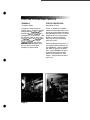
A FULL LINE OF EXCEPTIONAL PRODUCTS
STAIRCLIMBERS
The Best in the Industry
ELLIPTICAL STRIDING SYSTEMS
The New StairMaster FreeRunner
Our popular FreeClimber ~ stairclimber
line now offers you 5 different models
to choose from. These models include
the new fully featured FreeClimber
4600 PT and the cordless FreeClimber
4600 CL, along with the FreeCl imber
4400 PT and the cordless FreeClimber
4400 CL with Polar ~ Heart Rate
Monitor, and the cost-efficient
FreeClimber 4200 PT - all designed
especially for health clubs.
Introducing the StairMaster
FreeRunner™ 5400 ESS - a revolutionary new design that allows you
to vary your stride length from 10" to
40." Not only does this unique VSL
feature accommodate all users, it also
provides enhanced lower-body
conditioning - with greater
involvement of the glutes,
quadriceps, and hamstrings.
Other StairMaster ~ stairclimbers
include the Stepmill ~ 7000 PT - for the
most challenging stairclimbing
workout - as well as the legendary
StairMaster 4000 PT ~ .
For total-body condition ing, club
members will love the fact they can
use the handles on the StairMaster
FreeRunner 5400 for an effective
upper-body workout. These handles
can also be easily disengaged to rest
on the side of the machine.
Page v
•
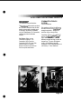
A FULL LINE OF EXCEPTIONAL PRODUCTS
TREADMILLS
New Models & Prices
In response to many requests we
received from our customers for a high
quality treadmill, StairMaster ~ has
selected the Quinton ~ treadmill as a
new addition to our product line - with
four different models to choose from the ClubTrack ~ 510, the ClubTrack ~ 510
Plus, the ClubTrack ~ 612 and the
ClubTrack ~ 612 Plus. Only Quinton
could match the StairMaster reputation for maximum performance,
durability, and product safety.
At last - a cordless line of variable
resistance exercise bikes that not only
provide the exciting workout programs
that StairMaster is famous for, but are
designed with such uncompromising
attention to every biomechanical
detail, they offer you extraordinary
safety and comfort.
•
•
STRATUS EXERCISE BIKES
The Highest Quality
Page vi
Introducing Stratus exercise bikes - a
new cordless variable resistance line
from StairMaster - that are available
with either an upright or recumbent
seat. Just like StairMaster's legendary stairclimbers, Stratus exercise
bikes are very different from other
models - simply because they feel so
good to use.
•
A FULL LINE OF EXCEPTIONAL PRODUCTS
CROSSROBICS~
The Ultimate Exercise Machines
The StairMaster ~ Crossrobics products
are innovative machines that combine
aerobic exercise with a weight stack
for strength conditioning. Available
only from StairMaster, the Crossrobics
machines provide the ultimate
workout.
•
•
StairMaster offers you two
Crossrobics machines - the
Crossrobics 1650 LE and the
Crossrobics 2650 UE Kayak. Both
products feature an easy-tooperate, first-time user option as
well as a quick-start feature.
STAIRMASTER STRENGTH
SYSTEMS
Feel the Difference
Club members will feel the difference
the first time they use StairMaster ~
strength equipment - designed to
work the way your body works.
Consisting of the Gravitron ~ 2000 AT
and the new Arcuate ~ and Linear'"
lines, StairMaster offers you 17
different strength training products to
choose from. To ensure the highest
quality, all StairMaster strength
equipment is now manufactured at our
own factory in Tulsa, Oklahoma.
Page vii
•
WARRANTY
This is to certify that the StairMaster® FreeClimber® exercise system is warranted
by StairMaster Sports/Medical Products, Inc. to be free of all defects in materials
and workmanship. This warranty does not apply to any defect caused by negligence,
misuse, accident, alteration, improper maintenance, or an "act of God ". This warranty
is non-transferable from the original owner.
If, within three years from the date of purchase, any part of the StairMaster
FreeClimber exercise system should fail to operate properly (except any accessories or the
battery on the 4600 Cl and the 4400 Cl), contact our Customer Service Department to
report the problem When calling, please be prepared to provide the customer service
representative with the following information:
•
•
•
•
•
Your name, customer number, shipping address, and telephone number
The model and serial number of the inoperable machine
The date(s) of purchase for the inoperable machine(s)
Your bi II ing address
This information will ensure that you are the only one ordering parts under your
warranty protection. If warranty replacement parts are shipped to you, you may be
requ ired to return the inoperable part. To facilitate this process, the following policy has
been established:
Please call our Customer Service Department to receive a return
goods authorization prior to shipment.
StairMaster Sports/Medical Products, Inc. will incur all freight
charges for warranty parts ordered for a machine that is less than 45
days old. The parts will be shipped to you via an overnight courier.*
You are responsible for freight charges on warranty parts for
machines that are more than 45 days old. You will not be responsible
for the return shipment of the inoperable parts.
Some inoperable warranty parts must be promptly returned to our
Customer Service Department. We will pay the shipping cost for the
inoperable warranty parts. Detailed instructions are included with
each warranty replacement part.
StairMaster Sports/Medical Products, Inc. neither makes, assumes nor
authorizes any representative or other person to make or assume for us, any other
warranty whatsoever, whether expressed or implied, in connection with the sale, service,
or shipment of our products. We reserve the right to make changes and improvements in
our products without incurring any obligation to similarly alter products previously
purchased. In order to maintain your product warranty and to ensure the safe and efficient
operation of your machine, only authorized replacement parts can be used . This warranty
is void if parts other than those provided by StairMaster Sports/Medical Products, Inc. are
used.
•
* Note: Aerosol products cannot be transported via air.
Page viii
•
PREFACE
Regular use of the Stairmaster\! ) FreeClimber\! ) exercise system is a safe and
effective way to develop aerobic fitness while conditioning the major muscles
of the lower body. In order to get the best results, and to keep your machine in
peak operating condition, you should carefully read and follow the guidelines
presented in this manual.
WHAT IS IN THIS MANUAL?
The first part of this manual includes sections on safety, installation, operating
instructions, and preventive maintenance. The second part contains detailed
information on problem troubleshooting and repair procedures. An Appendix at
the end of the manual provides additional information for the owner.
•
Throughout this manual, console keypad keystrokes are enclosed in [].
The names of the keys and special console operational modes are shown in
capital letters. For example, your machine is ready to use when the console is in
the ATTRACT mode. Press [MANUAL] to start the MANUAL exercise program.
WHAT IS THE STAIRMASTER FREECLIMBER EXERCISE SYSTEM?
The StairMaster FreeClimber exercise systems are vertical climbing machines
with an independent step action. The independent step action, combined with
the patented pedal geometry featured on all StairMaster steppers, provides an
aerobic workout equivalent to uphill running or climbing stairs, but without the
high-impact pounding to thejoints and muscles.
There are five FreeClimber models: the 4600 PT (Personal Trainer),
the 4600 CL (Cord Less), the 4400 PT, the 4400 CL, and the 4200 PT. All
FreeClimbers feature the Quiet Drive transmission. The 4600 PT and the
4600 CL have an adjustable tilting, full-featured console with a Light Emitting
Diode (LED) display. The 4400 PT and the 4400 CL have an upright, rail-less
design. The 4600 PT and the 4400 PT use an external power supply that is
plugged into an AC wall outlet. The 4600 CL and the 4400 CL use power generated during a workout to run the electronics. The 4600 PT and 4600 CL have
contact heart rate and Polar®heart rate monitoring. The 4400 PT and the 4400 CL
feature Polar\! ) heart rate monitoring. The 4200 PT uses an external power supply
to run a Liquid Crystal Display (LCD) console. This LCD console has less feedback
and fewer workout programs than the LED console on the 4600 PT ICL and the
4400 PT/CL.
•
Pageix
•
•
•
CONTENTS
SAFFETV GUIDELINES
1
INTRODUCTION
3
INSTALLATION INSTRUCTIONS
6
BASIC OPERATING INSTRUCTIONS
Genera l Guidelines for Safe Operati on
Your First Workout
The ATIRACT Mode
Basic Instructions for First-Time Users
4600/4400 PTICL Console Set-Up
4200 PT Console Set-Up
Begin Exercising
9
9
10
10
10
10
11
11
CONTACT HEART RATE (4600 PTICL ONLY)
13
POLAR- HEART RATE (4600/4400 PTICL ONLY)
14
FREECLIMBER 4600/4400 PTICL CONSOLE
Text Bar
Display
Function Keypad
Enterta inment Keypad (4600 PTICL)
Exercise Program Keypad
The Quick Start Option
The Fit Test
Preset Exercise Programs
4600 PTICL:
4400 PTICL:
The Jackpot Option
Turning the Jackpot Option On and Off
Custom Exercise Programs
Programming Your Workout
Using a Custom Program
Custom Scrolling Message
Editing The Scroll ing Message
Changing the Console Units and Language
Console Codes
15
16
16
16
18
18
19
19
21
21
21
22
23
23
23
24
24
25
26
26
Page x
:
CONTENTS
FREECLIMBER 4200 PT CONSOLE
28
Top Window
Workout Setup
Timer
Bottom Window
Keypad
Quick Start Option
28
28
30
30
31
31
MAINTENANCE INSTRUCTIONS
•
•
Helpful Hints
Tool List
Maintenance Records
Initial Service
Preventive Maintenance
Cleaning
Inspecting
Lubrication
Battery Charge
Battery Disposal
32
32
32
32
,
33
33
,
34
35
35
TROUBLESHOOTING
General Troubleshooting Guidelines
Electrical Troubleshooting
4600/4400 PT:
Alternator Test
Diode Test
Resistor Test
4600/4400 CL:
Battery Test
Alternator Test
Resistor Test
4600/4400 PT/CL Console Diagnostics
Display Test
Speaker Test
Keypad Test
Speed Test
Software Revision Level Test
Contact Heart Rate Test..
Polarl!!l Heart Rate Test
33
33
,
,
37
37
37
37
38
39
39
39
39
40
40
41
41
41
41
42
42
43
43
Page xi
•
CONTENTS
Mechanical Troubleshooting
•
45
PARTS REMOVAL AND REPLACEMENT
Covers
Mid Cover
Top Cover
Shield (4600 PT/CL)
Bottom Cover
Console
~
Console Adjustment (4600 PT/CL)
Poly-V and HTD Belt
Step Chain Reta iner
PedaI Arm Return Spri ng
Step Chain
Spring Pulley
Drive Chain
Drive Shaft Assembly
Pedal
Leveling Arm
Pedal Arm
Pedal Pad
Eccentric Hub Assembly
First Reduction Shaft Assembly
Handlebar (4400 PT/CL ,4200
Upper Handles (4600 PT/CL)
Side Handrails (4600 PT/CL)
Alternator
pn
"
,
,
48
48
48
48
49
49
50
50
50
51
51
52
53
53
54
56
56
57
57
58
58
58
59
59
60
GROUNDING INSTRUCTIONS
61
FCC COMPLIANCE
62
APPENDICES
•
Canad ian Doc Class BCompliance
Important Phone Numbers
Battery Recycling Centers
Figures 10-30
Page xii
62
63
64
66
•
CONTENTS
LIST OF TABLES
Table 1. Dimensions and Specifications for the
Sta irMasterl!l) FreeClimberl!l) Exercise Systems
Table 2. Fitness Rating Norms (METs)
Table 3: Character Codes for the Scrolling Message
Table 4. Console Codes
Table 5. Recommended Preventive Maintenance Schedule
5
20
25
27
36
LIST OF ILLUSTRATIONS
•
•
Figure 1: Major Parts - 4600 PTICL
Figure 2: Major Parts - 4400 PTICL
Figure 3: Level Adjusting End Caps
Figure 4: DC Power Connector
Figure 5: Correct Exercise Posture
Figure 6: 4600 PTICL Console Diagram
Figure 7: 4400 PTICL Console Diagram
Figure 8: 4200 PT Console Diagram
Figure 9: Grounding System
Figure 10: Parts Needing Periodic Maintenance
Figure 11 : Fina l Assembly - Left, 4600 PT
Figure 12: Fina l Assembly - Right,4600 PT
Figure 13: Final Assembly - Left, 4600 CL
Figure 14: Final Assembly - Right, 4600 CL
Figure 15: Covers - 4600 PTICL
Figure 16: Pedal Arm Assembly & First Reduction Shaft Assembly
(4600/4400 PTICL, 4200 PT)
Figure 17: Drive Shaft Assembly & Eccentric Hub Assembly
(4600/4400 PT/CL, 4200 PT)
Figure 18: Final Assembly - Left, 4400/4200 PT
Figure 19: Final Assembly - Right, 4400/4200 PT
Figure 20: Final Assembly - Left, 4400 CL
Figure 21 : Final Assembly - Right, 4400 CL
Figure 22: Covers - 4400 PTICL, 4200 PT
Figure 23: Cover Removal
Figure 24: Cover fasteners
Figure 25: Drive Chain tensioning
Figure 26: Belt Tension
3
4
6
7
12
15
15
28
61
66
67
68
69
70
71
72
73
74
75
76
77
78
79
80
81
82
Page xiii
•
SAFETY GUIDELINES
WHEN USING ELECTRICAL EQUIPMENT, ALWAYS FOUOW THESE BASIC PRECAUTIONS:
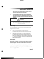
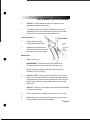
IMPORTANT SAFETY INSTRUCTIONS
This symbol appearing throughout this manual means
Attention! Be Alert! Your safety is involved.
The following definitions apply to the words "Danger" and "Warning"
found throughout this manual :
DANGER - Used to call attention to IMMEDIATE hazards which, if not
avoided, will result in immediate, serious personal injury or loss of life.
•
•
WARNING· Used to call attention to POTENTIAL hazards that could result
in personal injury or loss of life.
READ ALL INSTRUCTIONS BEFORE USING THE MACHINE.
.&.
.&.
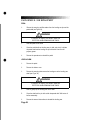
DANGER
To reduce the risk of electrical shock, always unplug
the external power supply from the AC wall outlet
before cleaning, maintaining, or repairing.
WARNING
To reduce the risk of burns, electric shock, or injury to
persons:
1.
The external power supply should always be unplugged from the AC wall
outlet before removing or installing parts. Never make adjustments or
repairs while an exercise program is in progress.
2.
Close supervision is necessary whenever the machine is used by or near
children, invalids, or disabled persons.
3.
Keep your hands away from all moving parts and keep your feet on the
pedals while exercising. Do not operate the machine with the side covers
removed.
Page 1
•
•
SAFETY GUIDELINES
4.
Use this machine only for its intended use as described in this Manual. Do
not use parts, attachments, or accessories other than those provided by
StairMaster® Sports/Medical Products, Inc.
5.
Do not use the external power supply if it has a damaged cord or plug, if it
is not working properly, if it has been dropped or damaged, or dropped into
water. Contact our Customer Service Department to arrange for the return of
damaged parts. Refer to the Appendix for the appropriate phone number.
6.
Connect the external power supply to a properly grounded AC wall outlet;
refer to the "Grounding Instructions" section. Keep all cords away from
heated surfaces.
7.
To disconnect the external power supply, remove the plug from the AC
wa II outlet.
8.
Never drop or insert any object into any opening on the machine.
9.
Do not operate where aerosol (spray) products are being used.
10. Always wear insulated gloves when handling batteries.
11 . Do not crush, incinerate, or dismantle the battery. The electrolyte
contains sulfuric acid which can cause serious damage to eyes
and skin. Should this occur, flush profusely with water and seek
medical attention.
12. Do not use the machine outdoors.
The safety level given by the design of this equ ipment can only be
maintained when the equipment is regularly examined for damage and wear.
Inoperable components shall be replaced immediately or the equipment shall be
put out of use until it is repaired. Failure to follow all guidelines may compromise
the effectiveness of the exercise experience, expose yourself (and possibly
others) to injury, and reduce the longevity of the machine. Follow all training
instructions listed in the manual and/or on the machine. Physical injury may
resu lt from incorrect or excessive training.
•
SAVE THESE INSTRUCTIONS
Page 2
•
INTRODUCTION
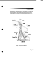
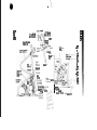
Before leaving the manufacturing facility in Tulsa, Oklahoma, your StairMaster ~
FreeClimber ~ exercise system was thoroughly inspected and tested to ensure
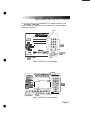
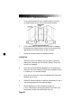
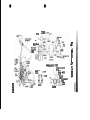
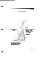
proper operation. The major parts of the machine are shown in Figures 1 and 2.
Console
Handles
/
•
Slield
Left Hanctail
Top Cover
/
/
\
Bottom Cover
LeftPedal
Transpor:t Whee I
SIDEVI~
Figure 1: Major Parts - 4600 Pl/Cl
•
Page 3
•
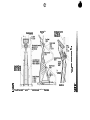
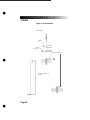
INTRODUCTION
and lebars
Top cover
•
Leve l-adju s ting
e nd c ap
Step Cha in
Figure 2: Major Parts· 4400 PTleL
•
Page 4
•
INTRODUCTION
Throughout this Manual, all references to the left or right side and to the front or
back are made as if you were on the machine, ready to exercise. For example, the
console is located on tile front of the machine. The dimensions and general
specifications of the machines are listed in Table 1.
Table 1. Dimensions and Specifications for the
StairMaster~ FreeClimber~ Exercise Systems
Physical Dimensions:
•
Length
Width at Front Leg (4400 PT/CL, 4200
Width at Front Leg (4600 PT/CL)
Height
Weight
4400 PT/CL, 4200 PT
4600 PT/CL
pn
41 inches (104 cm)
22 inches (56 cm)
32 inches (82 cm)
69 inches (176 cm)
126 pounds (55 kg)
155 pounds (70 kg)
Power Supply Specifications:
4600/4400/4200 PT (U.s., Canada, Japan)
4600/4400/4200 PT (International)
120 VAC, 50/60 Hz, 2.5 Amp
230 VAC, 50/60 Hz, 2.5 Amp
Batter:y Charger Specifications:
4600/4400 CL (U.s., Canada, Japan)
4600/4400 CL (International)
120 VAC, 50/60 Hz, 1 Amp
230 VAC, 50/60 Hz, 1 Amp
Internal Batter:y
6 volt, 1 Ah Lead-Acid battery
•
PageS
•
INSTALLATION INSTRUCTIONS
Assemble your machine before use. Machines shipped outside the United States
need to be uncrated before they can be assembled; refer to the "Uncrating
Instructions" included with your machine for the details.
1.
Remove all shipping material from your machine once it is in place.
2.
Make sure the machine is level before you use it for the first time. The
four rubber end caps (see Figure 3) are designed to compensate for
uneven floors. Each face of the caps is a different thickness. Twist the
caps to stabilize the machine.
Rotate cap to adjust
•
~
Level Adj usting
End Cop
(24329)
Figure 3: Level Adjusting End Caps
3.
•
Open the box you removed from the pedals. The box contains either an
external power supply (4600/4400/4200 PT only) or a wall-pack battery
charger (4600/4400 CL only). The battery charger is only used to
recharge a low battery.
Page 6
•
INSTALLATION INSTRUCTIONS
4.
•
If you have a 4600/4400 CL, skip to step 9. If you have a 4600/44001
4200 PT, connect the DC cable of the power supply to the connector
near the bottom of the left side cover (see Figure 4).
power supp ly here
Figure 4: DC Power Connector
5.
•
Place the power supply on the floor near an AC wall outlet. To reduce
the hazard of electrical shock, place the power supply in a location
away from the machine and away from exposure to perspiration. You
should not place your power supply on a carpet because it may over
heat.
Page 7
•
INSTALLATION INSTRUCTIONS
6.
Check to be sure that the input AC power rating marked on the power
supply matches the available power. If it does not, obtain the matching
power supply from StairMaster ~ Sports/Medical Products, Inc. before
proceeding any further.
&.
WARNING
TO REDUCE THE RISK OF ELECTRICAL SHOCK AND FIRE AND TO
PREVENT SEVERE DAMAGE TO THE MACHINE, USE ONLY THE POWER SUPPLY APPROVED FOR USE WITH THIS EQUIPMENT. IN ADDITION ,
YOUR MACHINE MUST BE PROPERLY GROUNDED.
•
•
7.
Connect the AC power cord to the AC wa ll outlet. Refer to the
"Grounding Instructions" section if the AC wall outlet does not
accept a three-prong plug.
8.
Watch the console. The 4600/4400 PT should scroll a copyright
message and then display a simulated EKG signal. The 4200 PT console
should run through a self test and then display a moving line in the
upper LCD window. If the console does not, unplug the power supply
and then plug it back in. If the console still does not power up correctly,
contact our Customer Service Department. Refer to the Appendix for the
appropriate phone number.
9.
If you have a 4600/4400 CL, step on the pedals to check for proper
operation. Once you step on the pedals, the console should produce an
audible sound and display a simulated EKG in the display area. If it does
not, connect the battery charger to the connector on the lower right
side. If the console still does not power up contact our Customer Service
Department. Refer to the Appendix for the appropriate phone number.
10.
The ATTRACT mode tells you the machine is ready to use. The 4600/
4400 PT ICl console displays a simulated EKG signal and the 4200 PT
displays a moving line in the upper LCD window when the console is in
the ATTRACT mode.
PageS
•
BASIC OPERATING INSTRUCTIONS
GENERAL GUIDELINES FOR SAFE OPERATION
A
WARNING
THESE GUIDELINES ARE DIRECTED TO YOU, AS THE OWNER OF THE MACHINE. YOU
SHOULD INSIST THAT ALL USERS FOLLOW THE SAME GUIDELINES. YOU SHOULD
MAKE THIS MANUAL AVAILABLE TO ALL USERS.
•
•
1.
Obtain a complete physical examination from your medical doctor and
enlist a health/fitness professional's aid in developing an exercise
program suitable for your current health status.
2.
When working out for the first time, use the MANUAL exercise program
at the lower speeds until you feel comfortable and capable of faster
speeds.
3.
The speed and duration of your exercise program should always be
subject to how you feel. Never permit peer pressure to exceed your
personal judgment whi le exercising .
4.
Overweight or severely deconditioned individuals should be particularly
cautious when using the machine for the first time. Even though such
individuals may not have histories of serious physical problems, they
may perceive the exercise to be far less intense than it really is,
resulting in the possibility of overexertion or injury.
5.
Although all equipment manufactured by StairMasterl!l Sports/Medical
Products, Inc. has been thoroughly inspected by the manufacturing
facility prior to shipment, proper installation and regular maintenance
are required to ensure safety. Maintenance is the sole responsibility of
the owner.
Page 9
•
BASIC OPERATING INSTRUCTIONS
YOUR FIRST WORKOUT ON THE STAIRMASTER GD FREECLIMBER GD
EXERCISE SYSTEM
The ATTRACT Mode
All workouts on the StairMaster FreeClimber exercise system start from the
ATTRACT mode. The 4600/4400 PTICL console displays an EKG signal or scrolls a
message in the text bar when it is in the ATIRACT mode. You must step on the
4600/4400 CL pedals before the console goes into the ATTRACT mode. The
4200 PT console displays a moving line in the upper LCD window when it is in the
ATTRACT mode.
You can customize the ATTRACT mode on the 4600/4400 PT ICL by
programming your own scrolling message. Refer to the "Customizing the Text Bar
Scrolling Message" section for instructions.
•
BASIC INSTRUCTIONS FOR FIRST-TIME USERS
1.
Warm up with light calisthenics and easy stretching exercises for at
least five minutes before beginning your exercise program.
A
WARNING
IF AT ANY TIME DURING YOUR WORKOUT YOU FEEL CHEST PAIN,
EXPERIENCE SEVERE MUSCULAR DISCOMFORT, FEEL FAINT, OR ARE SHORT OF
BREATH, STOP EXERCISING IMMEDIATELY. IF THE CONDITION PERSISTS, YOU
SHOULD CONSULT YOUR MEDICAL DOCTOR IMMEDIATELY.
2.
Hold onto the handlebars and step up onto the pedals. Stand up
straight. The pedals will sink slowly toward the floor.
3.
Select the MANUAL exercise program so you can control the pace of
your first workout and get used to the exercise motion.
4600/4400 PT/CL Console Set-Up
1.
•
Press [MANUAL] and then press [ENTER]. The console will return to the
ATTRACT mode if you do not press [ENTER] within ten seconds.
Page 10
•
BASIC OPERATING INSTRUCTIONS
2.
The console will prompt you to enter your body weight. Enter your
weight in pounds (or kilograms if the console is set up for metric units).
Correct entry errors by pressing [CLEAR] before you press [ENTER] .
3.
The console will prompt you to enter the workout time in one minute
increments between five and 60 minutes. Press [1], [0], [ENTER] to
exercise for ten minutes. If you do not start exercising within 30
seconds, the console will return to the ATTRACT mode.
4200 PT Console Set-Up
•
1.
Look at the upper LCD window. The arrow pointing to the word
"Program" should be flashing and "Pl" should be displayed.
Pl corresponds to the MANUAL program. Press [SELECT] .
2.
The arrow pointing to the word "Weight" will flash and "150" is
displayed. Use the [+ or - ARROW] to adjust your body weight. Press
[ENTER/SELECT] when it is correct.
3.
The arrow pointing to "Speed Level" will flash and "3" is displayed.
Press [SELECT] .
4.
The arrow pointing to the word "Time" will flash and the number "15" is
displayed. Press [- ARROW] to change the workout time to 10 minutes.
Press [SELECT].
Begin Exercising
•
1.
Take deep, comfortable steps. Do not let the pedals touch the floor or
contact the upper stop. When you begin to exercise, the MANUAL
program starts at level three.
2.
As you become comfortable with exercise motion, press
[+ INCREASE] and [- DECREASE] to adjust your climbing speed.
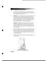
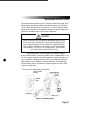
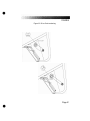
3.
Relax and stand up straight while exercising. Use the handlebars for
balance (see Figure 5) .
Page 11
•
•
•
BASIC OPERATING INSTRUCTIONS
4.
Select an intensity level that allows you to stay in the middle of the
pedal range of motion. Faster is not always better. Exercise at a level
that is consistent with your fitness level.
5.
4600/4400 PT: You can stop and rest as many times as necessary for up
to two minutes at each rest period during all programs except the
Constant Heart Rate program, which has unlimited fifteen second rest
periods. The console returns to the ATIRACT mode if you rest longer
than the allotted rest period. To return to your workout after a rest
period, simply raise either foot and start stepping again.
4600/4400 CL and 4200 PT: You can stop and rest as many times as
necessary for up to thirty seconds at each rest period. The console
returns to the ATIRACT mode if you rest more than thirty seconds. To
return to your workout after a rest period, simply raise either foot and
start stepping again.
6.
When you are finished with your workout, the machine will slow down
to the slowest speed . Lift one foot slowly until the pedal arm contacts
the upper stop. Place that foot on the floor. Repeat for the other foot.
Do not let the pedals slam into the upper stops, since this may cause
unnecessary wear and tear.
7.
Cool down after you get off the machine by walking or stretching for at
least five minutes.
Figure 5: Correct Exercise Posture
Page 12
•
CONTACT HEART RATE (4600 PT/CL)
The StairMasterilll FreeClimberilll features a digitized contact heart rate monitoring
system. Through the use of stainless steel sensors built into the upper handles
and sophisticated software, heart rate can be checked at any time during a
workout.
The heart generates a rhythmic, electron ic signal each time it beats (the
electrocardiogram or EKG signal). The sensors detect this electrical signal
through the hands when the sensors are gripped during a workout. The signal is
converted into a heart rate, which is displayed on the console.
•
•
The contact heart rate system is very accurate (within 3% of the
med ical standard), but its ability to detect a heart rate signal is influenced by
several factors. Movement of the muscles of the upper body produces an
electrical signal that will interfere with the detection of the heart rate signal by
the sensors. Movement of the hands whi Ie they are in contact with the sensors
also produces interference. Calluses and hand lotion act as an insulating layer
to reduce the signal strength. Also, the EKG signal generated by some individuals
is not strong enough to be detected by the sensors. Typically, these individuals
account for 5 - 7% of the population. Most people (between 93 - 95%) will
not have a problem with the system provided interference from movement is
minimal.
Lightly grip the sensors with each hand. The heart rate display is
shown automatically in the upper window the first time the sensors are touched .
A va lid signal is shown by a pulsating heart icon and the number of beats per
minute next to the word "Pulse". The heart icon will stop beating and two
dashes replace the numbers when the sensors are released or an invalid signal
is received .
Page 13
POLAR~ HEART
RATE (4600/4400 PT/CL ONLY)
The StairMaster ~ FreeClimber ~ 460014400 PTICL features Polar ~ heart rate
monitoring. The system consists of the receiver, located on the stepper, and a
transmitter belt (purchased separately), worn across your chest. The transmitter
belt senses the heart beat and sends a signal to the receiver. Your heart rate, in
beats per minute, is shown on the console text bar.
The transmitter belt attaches an identification number to your heart rate
signal. Once the receiver locks on to your signal, it will ignore all other signals
without your identification number. Now, two people can exercise side-by-side
without interfering with each other's heart rate signal.
•
•
Before you put the transmitter belt on, wet the two contact patches (the
grooved rectangles on the reverse side of the belt). Secure the transmitter belt as
high under the pectoral muscles (chest) as is comfortable. The transmitter belt
should fit snugly and comfortably and allow normal breathing.
When the console detects a heart rate signal, heart rate is shown in the
display automatically. The word "PULSE", your heart rate in beats per minute, and
a pulsing heart icon are displayed in the text bar.
If you display a statistic other than heart rate during your workout, you
can return to heart rate by pressing the white [0] key. Heart rate is part of the
workout stats scrolling display. Average heart rate is shown at the end of your
workout. If you wear a transmitter strap during the Fit Test, the average heart
rate at the end of each stage is automatically used when estimating maximum
aerobic capacity.
Page 14
•
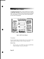
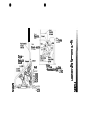
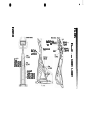
FREECLIMBER 4600/4400 Pl/CL CONSOLE
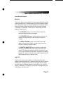
The StairMaster ~ FreeClimber ~ 4600/4400 PTICL console is divided into four
sections: the text bar, display, the function keypad, and the exercise program
keypad (see Figures 6 &7).
TQXt Bar
~
StaitMader
CLIMBING SYSTEMS
!. ,:v~~~
WlWl S!b;/IlJlSrer com
TO START
o
IIlICf&WOIIOtT
.....
-
I
Functioa
Ksv~d
::_.mMD1'O
::
.
-1OP5CIIIII
._
-.u- ..-
•
.:.111...:::.:.
r - - - : : :tHlMItWH:::-----,
[""I
------
,. ,.-,
[~II-=- I
f=1 t';i
Display
Figure 6: 4600 Pl/CL Console Diagram
....":::-.:=..-:7-.
- .--==..-..
............: =~
,-_-L.
-----.
F'undcn
ICltYPlld
:c:;:,.="r:.::
~=.::,..
,.....-~-.......
-~
tS!
Figure 7: 4400 Pl/CL Console Diagram
•
Page 15
•
FREECLIMBER 4600/4400 Pl/CL CONSOLE
TEXT BAR
Information regarding workout statistics and data entry is displayed or scrolled
across the text bar. A countdown timer is located directly above the words
"Interval Time". The timer shows the number of seconds remaining in the current
interval.
DISPLAY
A profile of all exercise programs (except MANUAL and FIT TEST) appears in the
display when you press its key. The taller the column, the faster the climbing
speed for that interval. The flashing column shows your current interval. The
flashing column moves from left to right across the display as you complete each
interval.
•
FUNCTION KEYPAD
The white function keypad is located on the right side of the console. Some of
the keys have two functions-data entry and workout statistics. Before you start
your workout, use the numbers on the keys to enter your personal data. During
and after your workout, use the workout statistics on the keys to display the
feedback.
Time. Displays the elapsed time of your workout, in minutes and
seconds.
Floors. Shows the total number of floors you have climbed. There are
16 eight-inch steps per floor.
Distance. Provides the equivalent horizontal distance you would have
traveled if you used the same amount of energy. There are 48 floors per
horizontal mile.
Watts. Displays the power output in watts (746 watts = 1 horsepower).
Since power is a rate, watts will not accumulate over time. During a
workout, this key displays the power output at that moment. Average
power is shown for the workout summary.
•
Page 16
FREECLIMBER 4600/4400 Pl/CL CONSOLE
Intensity Level . Shows the current level between 1 (the easiest) and
20 (the hardest). Shows the number of lights in the Manual program
between 1 and 14.
MEls. Gives you the relative energy cost of exercise. MET stands for
multiples of the resting metabolic rate. While you are sitting quietly,
your body consumes oxygen at the rate of about 3.5 milliliters per
kilogram of body mass per minute. When you exercise, your body needs
more oxygen in order to function. For example, exercising at 10 METs
requires ten times the resting rate of oxygen consumption, or about 35
milliliters per kilogram per minute. During a workout, this key shows the
current MET level. During the workout summary, the average MET level
is displayed.
•
Calories. Provides a running total of the number of Calories burned
during a workout.
Step Rate. Indicates the climbing speed in steps per minute. It is based
on an average eight-inch step.
Enter. Confirms workout selections and stores the information used by
the console to calculate workout statistics.
Zero. On 4600/4400 PTICL models, press this key to see your heart rate
during your workout. Press it during the workout summary to see your
average heart rate.
Clear. Erases information from the console memory if pressed before
[ENTER].
[+ INCREASE] I [- DECREASE]. Increases or decreases the
intensity level.
YeslNo (4400 Pl/CL). Respond to console prompts.
Start (4400 Pl/CL). If pressed while the console is in the ATTRACT
mode, the console will display the "Select A Program" prompt.
•
Page 17
•
FREECLIMBER 4600/4400 Pl/CL CONSOLE
Stop. If pressed at any time, the console will return to the ATTRACT
mode.
Workout Stats. If pressed during your workout, all workout statistics
continuously scroll across the text bar. Press any key to stop scrolling at
that statistic.
If pressed immediately after your workout, the workout
summary statistics will scroll once across the text bar. Press any
key to stop scrolling at that statistic.
•
If pressed while the console is in the ATTRACT mode, the final
totals from the last workout (if the workout was> 10 seconds) will
scroll across the text bar. This summary is stored in the console
memory until the next work out is started.
ENTERTAINMENT KEYPAD (4600 PT/CL)
The 4600 PT/CL comes equipped to facilitate the use of commercia l
entertainment systems.
Volume [+1-]. Increases (+) or decreases (-) the volume level.
Mute. Removes the audio sound from the headphones.
Channel [+1-]. Changes commercial entertainment system channels.
EXERCISE PROGRAM KEYPAD
The purple exercise keypad is located below the display and to the left of the
function keypad. While the console is in the ATTRACT mode, press one of the
exercise program keys to preview the desired workout.
The sequence of prompts for the preset exercise programs is slightly
different than the sequence described earlier for the MANUAL program. After
you press one of the exercise program keys, the exercise program profile is
scrolled across the display.
•
Page 18
•
FREECLIMBER 4600/4400 PT/CL CONSOLE
After the profile is scrolled, the prompts are:
•
•
•
•
"PRESS ENTER KEY TO ACCEPT"
"ENTER BODY WEIGHT" -- type in your body weight in
pounds (or kilograms if your console is set to metric units).
"ENTER LEVEL 1 ·20" -- select your intensity level with
level 1 being the easiest and level 20 the hardest.
"ENTER TIME 5·60" -- select the workout duration in one
minute increments from five to 60.
The Quick Start Option
•
You can quickly start any workout on the 4600/4400 PT/CL by first pressing one
of the purple exercise program keys * and then pressing [ENTER] twice. On the
4600 PT/CL you can alsojust press the [QUICKSTART] program key to begin
exercising. You do not have to enter any other information. The length of the
workout is set automatically and varies with the program. Quick starting
MANUAL gives you a 15 minute workout. The preprogrammed workouts last five
minutes for every thirty intervals. For example, a 60 interval program will last 10
minutes. All workout stats displayed at the end of a workout are based on a 175
lb. body weight.
*The [CONSTANT HEART RATE] program key on the 4600 PT/CL, and the
[FIT TEST] program key on the 4400 PT/CL do not have a quick start option.
The Fit Test
The Fit Test isa program that estimates your maximal aerobic capacity based on
your heart rate response to submaximal exercise. Start the 4600 PT/CL Fit Test by
pressing [+ INCREASE], [3], [4], [8], [ENTER] while the console is in the ATTRACT
mode. Start the 4400 PT/CL Fit Test by pressing [FIT TEST], [ENTER] while the
console is in the ATTRACT mode. You will be prompted to enter your age and
gender after a short message is scrolled across the display.
Once you have entered the required information, you will step at the
rate of 43 steps per minute for three minutes. At the end of three minutes, you
will need to enter your heart rate (if you are wearing a heart rate transmitter and
using a 4600 PT/CL, or 4400 CL, your heart rate is entered automatically).
•
Page 19
•
FREECLIMBER 4600/4400 Pl/CL CONSOLE
Note: Keep stepping until the end of the Fit Test.
The Fit Test will end ifyou stop stepping.
The console will prompt you to find your pu lse; use the artery below
your thumb in your wrist or the artery in the side of your neck. Start counting the
beats when the console prompts you-the first beat you feel is zero and then
one and so on. Enter the number of beats you counted in the ten seconds.
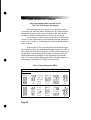
You will continue to exercise for three minute bouts of increasing intensity until you reach a point where you have entered two heart rate responses between 19 and 25 counts (115-150 beats per minute). The test typically lasts from
nine to 15 minutes.
•
At the end of the Fit Test, your results scroll across the text bar. Prior to
a three minute cool down, your estimated aerobic capacity, expressed in METs, is
shown. Next, your results will be compared to normative values for others of your
age and gender. These normative values are based on values developed by the
world renowned exercise physiologist, Dr. Per Olaf Astrand, and are shown in
Table 2. Your results are stored in the console until the next person starts an exercise program. Press [WORKOUT STATS] to review your results.
Table 2. Fitness Rating Norms (METs)
RatinQ
Gender/Aae
I
low
I
I
Fair
AveraQe
I Above Average I Superior
Men
.20-29.
30-~Q
40-~Q
'.
5p·~9,
60-69
.1) .1-12,3. '.
10·Q-11 :1.
8.,8-,1Q.Q
7.4-8.8
6.3-7.4
9.1-12.3
7.7-11 .1
<;8.,0
· -;7} .
-;7 J
· <;6,0 .
<4.8
8.,3-,9}
.8,0-,9.,4 .
7A-,8..8
.6,3-.7..7 .
5.1-6.3
JQ.0.-1.3} 14:0:1~.e
9.7-)3..4, ,: . 13.7:16.6
9.)-)2.. 8 ,:. 13,1:16.0
8.0-) 1..7. . '. 12,0:14.0
6.6-10.3
10.6-12.6
' .
Women
20-29.
.30-3Q
40-~9,
. 50-~Q
60-69
•
Page 20
'.
J2.6,-1.6.0 . '. 16,3:19.7
J1..4.-1,4 .p . 14:8:1$ . ~
JQ.3.-1 ,3.~ 13):17.1
· -;10.8
-;9)
-;8.,6
<7 .1
<6.0
'.
,
'.
"
12 : 6:1~.?
11.4-14.0
'
20,0:1- ,
18:6;+.
17:4:116.0+
14.3+
~
17:1;+16/8:1- .
16/3:1- ,
14,3:1- .
12.8+
•
FREECLIMBER 4600/4400 Pl/CL CONSOLE
Preset Exercise Programs
4600 PT/CL:
There are four preset exercise programs. The exercise speed during the programs
varies automatically over 14 increments within each of the 20 different intensity
levels. Varying the intensity of an exercise program does not change the profile
shown on the display. Change the intensity level of your workout by pressing
[+ INCREASE] or [- DECREASE] . For each level, the average energy cost of all
programs is about the same.
The FAT BURNER program is a 60 interval workout designed for
peoplejust starting a weight control program .
•
The FAT BURNER PLUS program is similar but has 90 intervals. It is
meant for the longer workouts you will need as your fitness level
increases.
The AEROBIC TRAINING program is a 60 interval workout with
slightly more varied speed changes. It is ideal for those long, slow
workouts to increase your aerobic capacity.
The CONSTANT HEART RATE program maintains a chosen target
heart rate by automatically varying the climbing speed during each
workout. The default target heart rate selected by the console is equal
to 70% of your maximum heart rate which is calculated by the following
equation: 220 - (Age) x .70. You may choose a different target heart rate
that is between 100 and 170 beats per minute.
4400 PT/CL:
There are seven preset exercise programs. The exercise speed during the
programs varies automatically over 14 increments within each of the 20 different
intensity levels. Varying the intensity of an exercise program does not change
the profile shown on the display. Change the intensity level of your workout by
pressing [+ INCREASE] or [- DECREASE]. For each level , the average energy cost
of all programs is about the same.
•
Page 21
•
FREECLIMBER 4600/4400 Pl/CL CONSOLE
The FAT BURNER program is a 60 interval workout designed for people
just starting a weight control program.
The FAT BURNER PLUS program is similar but has 90 intervals. It is
meant for the longer workouts you will need as your fitness level
increases.
The STEADY PACE and ROLLING HILLS programs are 30 interval
workouts with gradual speed changes. They are geared for those who
arejust starting to exercise or for those who need an easy day of
recovery exercise.
The AEROBIC TRAINING program is a 60 interval workout with
slightly more varied speed changes. It is ideal for those long, slow
workouts to increase your aerobic capacity.
•
•
The CROSS COUNTRY and SPEED TRAINING programs are 90
interval workouts with lots of speed changes to get your legs moving.
Think of the terrain you would find on a hike cross country.
THE JACKPOT OPTION
When you finish your workout, a "GOAL ATTAINED" message is
normally displayed in the text bar. This message may be replaced by a Native
American casino style slot machine. When the wheels of the slots stop turning,
the console display will spell out either "YOU WIN " or "THE END ". The odds of
winning may be programmed anywhere from l-in-l to l-in-999. The computer
will then randomly select a winner and display "YOU WIN", otherwise it will
display "THE END." Workout statistics are shown, as usual, after thejackpot
message.
Commercial owners often use thejackpot option to further stimulate
consumer interest in their establishment and to add variety to their overall
workout program. Many such owners offer a prize or some tangible incentive for
individuals who win while using thejackpot option. If there is only one prize, you
should remember to disable the option after there is a winner. Thejackpot option
remains in effect until disabled by entering zero odds. StairMaster ~ assumes no
liabi lity stemming from the use of thejackpot option. Laws or ordinances in your
area may govern the use of this option.
Page 22
•
FREECLIMBER 4600/4400 Pl/CL CONSOLE
Turning the Jackpot Option On and Off
•
1.
The computer must be in the ATTRACT mode. Press [I NCREASE], [7707],
[ENTER].
2.
The prompt "ENTER ODDS" will appear in the console display. Enter the
numeric odds you have selected, between 1 and 999.
3.
Thejackpot results are saved in the console memory unti I the next
workout is started. Press [WORKOUT STATS] to review the results.
4.
Program the odds to zero to turn thejackpot option off and to return to
having the "GOAL ATTAINED" message appear after you finish your
workout.
CUSTOM EXERCISE PROGRAMS
The 4600 PT/CL console has enough memory space for six custom exercise
programs. The 4400 PT/CL console has enough memory space for nine custom
exercise programs. Only the exercise profile is saved. You must enter your body
weight, the intensity level, and the workout time when you use the custom
program. Custom programs have a quick start option, but the time is limited to
five minutes.
Programming Your Workout
•
1.
The console must be in the ATTRACT mode. Press [+ INCREASE],
[1], [6], [5], [0], [ENTER]. Press the exercise program keypad
button that you want to assign to your custom program .
2.
If you select an exercise program keypad button that is already
programmed, the profile will appear; it can be modified or
completely rewritten. If the exercise program keypad button was
not previously programmed, you will see a single row of dots
along the bottom of the display.
3.
The flashing dot or column indicates wh ich interval can be modified.
Press the [+ INCREASE] or [- DECREASE] to make the column
Page 23
•
FREECLIMBER 4600/4400 Pl/CL CONSOLE
taller or shorter. Press [ENTER] to move one column to the right
and [CLEAR] to move one column to the left.
4.
When all of the intervals are correctly programmed, press
[0- 4600 PTfCl] or [YES - 4400 PTfCl] to save the profile. Press
[STOP - 4600 PTfCl] or [STARTfSTOP - 4400 PTfCl] to abort the
programming process without saving the profile.
Using a Custom Program
•
•
1.
Press [- DECREASE] and the exercise program keypad button you
assigned to the custom program.
2.
Enter your body weight, the intensity level and the workout time
in response to the prompts.
CUSTOM SCROLLING MESSAGE
The message that scrolls across the text bar during the ATTRACT mode can be
replaced with a message of your choice. The console accepts messages up to
128 characters in length, including spaces. To program your message:
1.
Encode your message using the character codes listed in Table 3.
2.
While the console is in the ATTRACT mode, press [+ INCREASE], [7],
[6], [0], [7], [ENTER] .
3.
Enter the two-digit code for each letter of your message. The
letter will appear in the text bar as you press the second digit of
each code. Do not press [ENTER] between the code numbers.
4.
For example, to program the message "EXERCISE IS FUN", press
[+ ARROW], [7], [6], [0], [7], [ENTER] . Then press [1], [5], [3], [4], [1], [5],
[2], [8], [1], [3], [1], [9], [2], [9], [1], [5], [1], [0], [1], [9], [2], [9], [1], [0], [1],
[6], [3], [1], [2], [4], [ENTER] . At that point, your message will begin
scrolling. The console is again in the ATTRACT mode.
5.
If you make a mistake while entering the codes, press [CLEAR] to
erase the last character entered.
Page 24
•
FREECLIMBER 4600/4400 Pl/CL CONSOLE
Table 3: Character Codes for the Scrolling Message
Character
Code
Character
Code
Character
Code
0
1
2
3
4
5
6
7
8
9
00
01
M
23
24
25
26
27
28
29
30
31
32
33
34
35
36
37
38
39
40
41
42
43
44
45
r
46
47
48
49
50
51
52
53
54
55
56
57
58
59
60
61
62
63
64
65
66
67
68
SPACE
A
B
C
D
E
F
•
G
H
I
J
K
L
02
03
04
05
06
07
08
09
10
11
12
13
14
15
16
17
18
19
20
21
22
N
0
P
Q
R
S
T
U
V
W
X
Y
Z
A
0
0
B
A
A
0
t
N
A
i
t
A
C
E
L
+
$
,
%
?
!
#
,
)
(
/
EDITING THE SCROLLING MESSAGE
•
1.
While the console is in the ATTRACT mode, press [+ INCREASE], [7],
[6], [OJ, [7], [ENTER] to display the first character of the message
onto the text bar.
2.
Press [+ INCREASE] or [- DECREASE] to scroll through the message
character-by-character.
3.
Press [CLEAR] to delete the last character displayed on the text bar.
Press [0] to end the editing process.
Page 25
•
•
FREECLIMBER 4600/4400 Pl/CL CONSOLE
4.
To edit multiple characters at one time, press [9], [9], [ENTER] to erase
all of the characters to the right of the last character displayed on the
text bar.
5.
To erase the entire message, press [+ INCREASE], [1], [0], [5], [ENTER]
while in the ATTRACT mode.
6.
The ed ited message will scroll across the text bar. If you have erased
the entire message, the text bar area will be blank during the ATIRACT
mode.
7.
Press [+ INCREASE], [2], [1], [2], [3], [ENTER] to display the default
scrolling message on the text bar.
8.
Press [+ INCREASE], [2], [1], [2], [1], [ENTER] to display your custom
scrolling message on the text bar.
CHANGING THE CONSOLE UNITS AND PROMPT LANGUAGE
The console is set at the manufacturing facility to English language prompts
and English units. While the console is in the ATTRACT mode, you can set the
console for foreign language prompts or metric units.
1.
To change the prompt language, press [+ INCREASE], [7], [4], [2], [4],
[ENTER]. Press the code number for the desired language (see Table 4)
and then press [ENTER].
2.
To change the console to metric units, press [+ INCREASE], [9], [7], [6],
[0], [ENTER] and then [1] . Press [+ ARROW], [9], [7], [6], [0], [ENTER] and
the [0] to change back to English units.
CONSOLE CODES
The console codes and the corresponding functions are listed in Table 4. Without
standing on the pedals, press [+ INCREASE] before pressing the code's number
keys, and then press [ENTER]. Some codes, like the one to change the language
of the console prompts, have options that require you to press a second code
number and then [ENTER] to select that option.
•
Page 26
FREECLIMBER 4600/4400 Pl/CL CONSOLE
Table 4. Console Codes
Function
Code
Clears the custom programmed scrolling message
105
107
•
0
1
2
3
4
108
Heart rate software test
1650
Programs a custom workout
2121
Turns on the custom scrolling message
2123
Turns off the custom scrolling message
7424
Changes the language of the console prompts
7607
99
7704
9760
9766
Turns on the custom message option
Text bar scrolling message editing function
Displays machine usage information
7703
7705
•
Activates the Diagnostic mode
Display test
Speaker test
Keypad test
Speed test
Software revision test
0
1
Allows you to turn the console speaker on or off
Turns the speaker on
Turns the speaker off
0
1
Allows you to turn the Heart Rate feature on or off
Turns the Heart Rate feature on
Turns the Heart Rate feature off
0
1
Allows you to change the units displayed by the console
Changes the console to English units
Changes the console to metric units
0
1
Allows you to change the software version
Changes to 4400 PT software
Changes to 7000 PT software
97405
Changes the maximum workout time
52475
Reset time limit to 60 minutes
Page 27
•
FREECLIMBER 4200 PT CONSOLE
The StairMaster ~ FreeClimber ~ 4200 PT console is divided into two LCD display
windows. There is a four-function keypad located below the bottom window (see
Figure 8). While you are exercising, the bottom window scrolls through a display
of four workout statistics. An arrow on the side of each LCD window points to
the name of what is being displayed.
•
•
l
a.... · "._~._~
-~
Figure 8: 4200 PT Console Diagram
TOP WINDOW
The top LCD window displays information while you set up your workout. It also
displays elapsed time during your workout or during your rest period.
Workout Setup
1.
•
While the console is in the ATTRACT mode, either press [START/STOP]
or step on the pedals. Look at the top LCD window.
Page 28
•
FREECLIMBER 4200 PT CONSOLE
2.
The arrow pointing to the word "Program" should be flashing and "Pl"
should be displayed. Pl corresponds to the MANUAL program. Use the
[+ or - ARROW] to change the workout option. "P2" corresponds to
Steady Pace, "P3" to Fat Burner, and "P4" to Aerobic Training. The
different workout option profiles are shown on the right side of the
console.
3.
When the correct workout option is displayed on the top LCD window,
press [ENTER/SELECT].
4.
The arrow pointing to the word "Weight" will flash and the number
"150" will be displayed. Use [+ or - ARROW] to adjust it to your body
weight. Press [ENTER/SELECT] when it is correct.
5.
If you selected a workout option other than "Pl" (MANUAL), the arrow
pointing to the words "Speed Level" will flash and the number "10" will
be displayed. Adjust the level between 1 (the slowest) and 20 (the
fastest) with [+ or - ARROW]. Press [ENTER/SELECT] when it is correct
•
•
If you selected MANUAL, your workout will start at speed
level 3. Levell is the slowest and level 20 is the fastest.
Use the [+ or - ARROW] to adjust the cI imbing speed once your
workout begins.
6.
The arrow pointing to the word "Time" will flash and the number "15"
will be displayed. Press [+ or - ARROW] to adjust the length of your
workout between 5 and 45 minutes.
7.
Press [ENTER/SELECT]. Begin exercising.
Page 29
FREECLIMBER 4200 PT CONSOLE
Timer
During your workout, the top window keeps track of your workout time in minutes and seconds. The display arrow points to the word "Time" on the console.
You may rest for up to 30 seconds at any time during your workout.
Either stop stepping or press [START/STOP] to begin your rest period. To resume
your workout, step on the pedals. If you press [START/STOP] during a rest period,
or if you rest for more than 30 seconds, the console will return to the AITRACT
mode.
BOTTOM WINDOW
•
The bottom LCD window keeps track of four different statistics during your workout: the number of Calories burned, the climbing speed in steps per minute, the
total number of floors climbed, and the total distance covered. As the console
scrol ls through each statistic, an arrow on the side of the display window points
to the name of what is being shown.
Calories. Provides a running total of the number of Calories burned
during a workout.
Steps/Min. Indicates the climbing speed based on an eight-inch step.
Floors. Shows the total number of floors you have climbed. There are
16 eight-inch steps per floor.
Distance. Provides the equivalent horizontal distance you would have
traveled if you used the same amount of energy. There are 48 floors per
horizontal mile.
When the display arrow points to the word "Scan", all workout
statistics are scrolled. Press [ENTER/SELECT] during your workout to lock the
bottom display window on anyone statistic. For instance, press [ENTER/SELECn
three times to lock the display on the total number of floors climbed . Press
[ENTER/SELECT] two more times to resume scrolling the statistics. During rest
periods, only Calories, Floors, and Distance are shown (even if the display was
locked on one statistic). At the end of your workout, these same three statistics
are shown one last time.
Page 30
•
FREECLIMBER 4200 PT CONSOLE
Keypad
ENTER/SELECT. During workout setup, press this key to enter your
personal information and then move to the next entry. During your
workout, press this key to lock the bottom display window on anyone
statistic or to return to the scrolling mode.
+ or· ARROWS. During workout setup, press these keys to adjust your
personal information before you press [ENTER/SELECT]. During your
workout, use these keys to adjust the level (or climbing speed) .
•
•
START/STOP. Press this key while the console is in the ATTRACT mode
to begin the workout setup. If pressed at any time during workout setup,
all entries are cleared and workout setup starts over again. If pressed
during a workout, a 30 second rest period is started. If pressed during a
rest period, the console returns to the ATTRACT mode.
QUICK START OPTION
You can quickly start the MANUAL program (IP1") by pressing
[ENTER/SELECT] twice (double-clicking) at the start of workout setup.
The workout statisics are based on a 150 pound person, the climbing speed
starts at level 3, and the workout time is set to 15 minutes. Use the
[+ or - ARROW] to adjust the climbing speed once your workout starts.
Page 31
MAINTENANCE INSTRUCTIONS
HELPFUL HINTS
Read all maintenance instructions thoroughly before beginning work. In some
cases, an assistant is required to perform the necessary tasks.
All references to the right or left side and to the front or back are
made as if you were on the machine ready to exercise. For example, the console
is located on the front of the machine. Major component names and locations
are shown in Figure 10. When ordering parts, reference the part number in
parentheses next to the part's description on the figures.
TOOL LIST
The following tools are needed to perform service and maintenance:
•
•
•
•
•
•
•
•
standard screwdriver
• phillips screwdriver
combination wrenches (sizes 7/16 - 3/4") • adjustable wrench
combination pliers
• locking pliers
volt-ohm meter (multimeter)
• wire stripper/crimper tool
allen wrench set (sizes 5/64 _1/4")
• external snap ring pliers
shop goggles or other eye protection
• torque wrench
socket set or nut driver set (sizes 1/4 - 3/4" in 1/16" increments)
MAINTENANCE RECORDS
The 4600/4400 PT/CL console will keep track of the following data on
machine usage:
•
•
•
•
•
The number of hours the power supply was turned on.
The number of hours the machine was in use.
The total number of floors climbed .
The number of exercise programs started.
The hours of MANUAL use.
To display the data, press [+ INCREASE], [7], [7], [0], [3], [ENTER] while
the console is in the ATTRACT mode. The console will display the data in the
sequence listed above. The machine may show a few hours of use due to testing
at the manufacturing facility.
•
Page 32
•
MAINTENANCE INSTRUCTIONS
The 4200 PT console keeps track of the number of hours the machine
was used and the total number of floors climbed. From the ATTRACT mode, press
[+ ARROW] and then double-click [RESET] . The hours are shown in the top LCD
window and the total floors are shown in the bottom LCD window.
INITIAL SERVICE
Upon receiving your machine, use a soft, clean towel to wipe off the dust which
may have accumulated during shipping. Your new machine will require minor
assembly. Refer to the "Installation Instructions" section for details.
PREVENTIVE MAINTENANCE
•
Most of these preventive maintenance procedures can be performed after
removing the mid cover. The preventive maintenance schedule is summarized in
Table 5. The schedule is based on normal usage in a commercial health club
environment; adjust the schedule to meet actual machine usage. Refer to the
"Parts Removal and Replacement" section for all disassembly and assembly
instructions.
Cleaning
1.
DO NOT USE GLASS CLEANERS OR ANY OTHER HOUSEHOLD CLEANER
ON THE CONSOLE. Clean the console daily with a water-dampened
cloth and wipe dry after cleaning.
2.
Clean the exterior of the machine daily using soap and water or a
diluted household cleaner such as Fantastic ~ .
3.
Thoroughly clean the entire machine, including the interior, at least once
a week (see Table 5).
Inspecting
1.
•
Inspect the frame for any rust, bubbling, or paint chips during the
weekly cleaning. The salt in perspiration can damage the unpainted
surfaces.
Page 33
•
MAINTENANCE INSTRUCTIONS
2.
Inspect the Poly-V belt and HTD belts for excessive wear during the
quarterly lubrication. Adjust the belt tension if necessary.
LUBRICATION
There are nine components that need periodic lubrication: the drive chain, the
step chains, the pedal arm return springs, the step chain connection points, the
pedal arm bushings, the leveling arm bushings, the spring pulley shafts, the
pedal shafts and the leveling arm pins. These parts are shown in Figure 10.
Remove the bottom cover to get to the components.
•
•
1.
Place a protective mat on the floor while you lubricate your machine. A
rubber floor mat is ava ilable from StairMaster ~ Sports/Medical
Products, Inc.
2.
Lubricate the drive cha in and the step chains weekly. Try to penetrate
the entire length of the chains with 30W motor oil.
3.
Remove the drive chain and step chains every three months to
thoroughly clean and lubricate them. Use a mild degreaser and a stiff
brush to remove dirt and corrosion from the chains.
4.
Unhook the pedal arm return springs from the spring hanger every
week. To protect them from corrosion, wipe the entire length of each
pedal arm return spring with a cloth dampened with 30W motor oil
before reconnecting it. Replace the spring if it is rusty or otherwise
damaged.
5.
Remove the double pitch master link from the step chain connection
points every three months. Clean the master link and the bushing in the
pedal arm. Lubricate the master link and bushing with a thin coat of
mUlti-purpose grease before reassembling.
6.
Remove the pedal arms and leveling arms every three months. Clean the
pedal arm and leveling arm shafts and bushings with a clean cloth.
Protect the shafts from corrosion by wiping them with a cloth dampened
with 30W motor oi I.
7.
Remove the spring pulleys every three months. Clean the spring pulley
Page 34
•
MAINTENANCE INSTRUCTIONS
shafts with a dry cloth. Protect the shafts from corrosion with a thin
coat of mUlti-purpose grease before reassembling .
8.
Remove the pedals every three months. Clean the pedal shaft and
leveling arm pin with a dry cloth. Protect the pedal shaft and leveling
arm pin from corrosion with a light coat of mUlti-purpose grease before
reassembl ing.
.&..
WARNING
TO REDUCE THE POSSIBILITY OF SLIPPING, BE SURE THE PEDAL
AREA IS FREE OF GREASE OR OIL. WIPE ANY EXCESS OIL OFF
THE MACHINE SURFACES.
•
Battery Charge
If you have a 4600/4400 CL, remove the bottom cover and check the battery
voltage level every three months.
1.
Using your multimeter, touch the red lead to the positive
terminal of the battery and the black lead to the negative terminal.
2.
If the voltage level is less than 6.1 VDC, charge the battery. Plug
the wall pack battery charger into the connector located near the
bottom of the left bottom cover. Charge the battery for approximately
24 - 48 hours and then recheck it. It is okay to use machine while the
battery charger is connected.
Battery Disposal
When ordering new batteries, you will need to properly dispose of (recycle) your
old lead-acid batteries. Most federal and state regulations requi re lead-acid
batteries be recycled.
•
Do not throwaway old batteries. Lead is a toxic heavy metal hazardous
to living organisms. Disposal instructions and a list of recycling centers are
tabulated in the Appen.dix. If you have questions, contact the Customer Service
Department at (800) 331-3578.
Page 35
•
MAINTENANCE INSTRUCTIONS
Table 5. Recommended Preventive Maintenance Schedule
PART
LUBRICANT
Wipe Clean
Daily
Water
N/A
Covers
Clean and
inspect
Daily
Diluted
house hold
cleaner
N/A
Lubricate
Each week or
after 70 hours
N/A
30W motor
oil
Remove. clean
and lubricate
Every 3
months or 900
hours
Degreaser
30W motor
oil
Step Chain
Connection
Points
Clean and
lubricate
Every 3
months or 900
hours
Clean. dry
rag
Multi
purpose
grease
Spring
Pulley
Shafts
Clean and
lubricate
Every 3
months or 900
hours
Clean. dry
rag
Multi
purpose
grease
Pedal
Shafts &
Leveling
Arm Pins
Clean and
lubricate
Every 3
months or 900
hours
Clean. dry
rag
Multi
purpose
grease
Inspect and wipe
Each week or
N/A
Clean. oil
dampened
rag
Pedal Arm
Return
Springs
•
CLEANER
Console
Drive and
Step Chains
•
RECCOMENDED
FREQUENCY
ACTION
down
after 70 hours
Pedal Arm
Shafts
Clean and
lubricate
Every 3
months or 900
hours
Clean. dry
rag
Multi
purpose
grease
Battery
Check Voltage
Every 3
months or 900
hours
N/A
N/A
Belts
Inspect & adjust
tension
Every 3
months or 900
hours
N/A
N/A
-Note: Use of lubricants other than those specified will result in
diminished performance and a shorter life span for that part.
Page 36
•
TROUBLESHOOTING
GENERAL TROUBLESHOOTING GUIDELINES
Th is troubleshooting section is organized into three basic problem sections:
electrical troubleshooting, console diagnostics, and mechanical troubleshooting.
Once you have identified the problem section, perform all the tests in the same
order as written. To order a replacement part or for help with troubleshooting,
contact our Customer Service Department. Refer to the Appendix for the
appropriate phone number.
ELECTRICAL TROUBLESHOOTING
•
•
The 4600/4400 PT electrical system has three major components: the power supply, the power cables and the console. The 4600/4400 CL also has three major
components: the battery, the power cables, and the console. The console, power
supply and battery are not serviceable by the owner. If any of these parts are inoperable, they must be replaced. Opening the console or the power supply will
void the warranty.
4600/4400 PT:
1.
Use a voltmeter set on VAC to verify that the AC wall outlet has 100
to 120 VAC (or 220 to 240 VAC, if applicable). If you do not have a
voltmeter plug in an alternate AC-powered device (a lamp, for example).
If the device does not work when plugged into the AC wall outlet,
consult an electrician for further assistance and then retest the AC wall
outlet.
2.
Plug the power supply into the wall outlet. The green Light Emitting
Diode (LED) on the power supply should be on. If the LED does not light
up, replace the power supply.
3.
Disconnect the DC cable from the left side panel. Set the voltmeter to
VDC and test for 12 - 19 VDC in pins #1 (+) and #2 (-). Replace the
power supply if the voltage reading is outside the specified range.
4.
Remove the bottom cover and connect the DC cable to the power
connector on the left side of the frame. Locate the black and white
wires on the backside of the power connector.
Page 37
ELECTRICAL TROUBLESHOOTING
5.
Follow the white power connector wire to the where it plugs into the
main cable white wire, and disconnect it from the main cable
white wire.
6.
Set your voltmeter to VDC. Connect the positive lead of your
voltmeter to the white wire from the power connector and touch the
gray casing of the alternator with the negative lead of your voltmeter.
7.
DC voltage measured should be 12 - 19 VDC. Replace the power
connector if the voltage is not the same value as in step 3. Connect
the two white wires.
8.
Remove the console knobs from the back of the console, lift the console
up, and disconnect the main cable from the console.
9.
Test for 12 - 19 VDC in pins #1 (+) and #9 (-) in the main cable
connector. Replace the main cable if the voltage reading is not
the same as in step 7.
10.
If all voltage readings have been within the specified range and the
console will not power up, the console should be replaced .
Alternator Test
11.
Check for loose wiring connections on the alternator, diode and load
resistor (see Final Assembly Figure).
12.
Perform the Positive Output to Field test on the alternator:
•
•
•
•
•
•
Page 38
Turn the power off
Remove the white wire from the B+ terminal on the alternator
Remove the brown wire from the field terminal on the alternator
Place a short wire with alligator clips on the B+ terminal and the
field (FLD) terminal of the alternator
Step on the machine for approximately 10- 15 seconds
If full resistance is achieved during this time, your alternator
has correct current flow. If no resistance is achieved, replace
the alternator.
ELECTRICAL TROUBLESHOOTING
Diode Test
13.
Remove the brown wire and diode from the field termina l of the
alternator and set your voltmeter to the Ohms setting.
14.
Place one lead from the voltmeter on each end of the diode, and then
reverse the leads. A diode that is good will show a high reading in one
direction and a low reading when the leads are reversed. Replace the
diode if the readings recorded are both high or both low.
Resistor Test
15.
•
Remove one wire from the load resistor (see Final Assembly Figure)
and place one lead from the voltmeter on each of the threaded posts on
the load resistor. Replace the load resistor if the voltmeter does not
read 0.5 Ohms (± 10%).
4600/4400 CL:
Battery Test
1.
Remove the mid cover and top covers and unplug the battery from the
power control board. Locate pins #1 & 2 in the end of the cable. Use a
voltmeter to verify that the voltage is a minimum of 6.1 VDC. Reconnect
the battery back to the power control board and install the battery
charger for at least 24 hours if the voltage measured is below 6.1 VDC.
2.
Remove the console knobs from the back of the console, lift the console
up, and disconnect the main cable from the console.
3.
Step up on the machine. With the voltmeter set to DC voltage, test
for greater than 6.1 VDC in pins #1 (-) and #8 (+) in the main cable
connector while stepping. Replace the main cable if the voltage reading
is less than 6.1 VDC. Next, Check for continuity in the ma in cable (see
Final Assembly Figure).
4.
If all voltage readings have been within the specified range and the
console will not power up, the console should be replaced .
Page 39
ELECTRICAL TROUBLESHOOTING
Alternator Test
5.
Perform the Positive Output to Field test on the alternator:
•
•
•
•
•
•
•
•
Unplug the battery from the power control board
Remove the white wire from the B+ terminal on the alternator
Remove the brown wire from the field terminal on the alternator
Place a short wire with alligator clips on the B+ term inal and the
field (FLD) terminal of the alternator
Step on the machine for approximately 10 to 15 seconds
If full resistance is achieved during this time, your alternator
has correct current flow. If no resistance is achieved, replace
the alternator.
Resistor Test
6.
Unplug the load resistor from the power control board and set your
voltmeter to Ohms. Place one lead from the voltmeter on each of the
threaded posts on the load resistor. Replace the load resistor if the
voltmeter does not read 2.5 Ohms (± 10%).
7.
If the problem sti II exists, contact the Customer Service Department at
800-331 -3578.
Page 40
•
4600/4400 PTICL CONSOLE DIAGNOSTIC TESTS
The following tests are performed while the console is in the DIAGNOSTIC mode.
While the console is in the ATTRACT mode, and without stepping on the pedals,
press [+INCREASE], [1], [0], [7], [ENTER] to activate the DIAGNOSTIC mode. The
numbers will not appear on the display as you enter them. If the console fails any
test, the console should be replaced or exchanged. To return to the ATTRACT
mode, press either [CLEAR] or [START/STOP] while in the DIAGNOSTIC mode.
Display Test
Use this test if the console display or text bar exhibits blank spots during use.
This test checks for inoperable Light Emitting Diodes (LEOs) in the console display and the text bar. If any LED will not light, replace the console.
•
1.
From the DIAGNOSTIC mode, press [0] to start the test.
2.
All LEOs in the console display will flash on and off as a block.
3.
Press [CLEAR] to end the test.
Speaker Test
Use this test to make sure the console speaker is fully operational. The speaker
will ascend and then descend through the musical scale.
1.
From the DIAGNOSTIC mode, press [1] to start the test.
2.
Press [ENTER] to pause the test. Press [CLEAR] to end the test.
Keypad Test
Perform this test if you are having trouble entering data into the console. If you
cannot enter the DIAGNOSTIC code due to an inoperable keypad, replace the
console.
•
1.
From the DIAGNOSTIC mode, press [2] to start the test.
2.
The display LEOs will light up in an L-shaped formation, representing
the keypad matrix. Pressing a button on either the exercise program
Page 41
•
4600/4400 PTICL CONSOLE DIAGNOSTIC TESTS
keypad or the function keypad will light an LED within the outline on the
display that corresponds to that button's position on the console.
3.
Firmly press each button. If the LED corresponding to the button
you pushed does not light up, the keypad is bad and the console should
be replaced .
4.
Press [CLEAR] to test the LED and then end the test 10 seconds later.
Speed Test
Use this test to verify the electronic speed control routines of the console. You
will need to briefly exercise on the machine for this test.
•
1.
From the DIAGNOSTIC mode, press [3] to start the test.
2.
The console will be set at a certain speed . The alternator speed, in
RPMs, is displayed on the text bar as "Target" and a single column of
lights will light up on the left side of the display.
3.
Begin exercising. As you move the pedal arms, the text bar will
alternately show the actual RPM and the target RPM .
4.
Press [CLEAR] to return to the DIAGNOSTIC mode.
Software Revision Level Test
This test allows you to check the version number of the software installed in the
console.
•
1.
From the DIAGNOSTIC mode, press [4] to start the test.
2.
The software version number will be scrolled across the text bar.
The console automatically returns to the DIAGNOSTIC mode.
Page 42
•
4600/4400 PTICL CONSOLE DIAGNOSTIC TESTS
Contact Heart Rate lest (4600/4400 Pl/Cl only)
The contact heart rate system is made up of the console and the contact heart
rate handles. You can test each component by performing the following steps:
•
1.
While the console is in the ATIRACT mode (noted by a simulated EKG
signal in the console display), or at the "SELECT A WORKOUT" prompt,
press [+INCREASE], [1], [0], [8], [ENTER] .
2.
After approximately ten seconds a flashing. should be displayed in
the console text bar. Your heart rate, in beats per minute, will show next
to the heart icon. If the heart icon does not show, or if your heart rate is
not displayed in the text bar, you have a problem with either the
console or the contact heart rate handles.
3.
If possible, replace or exchange your console with a console (from
the same type of machine) you know is working and retest the
machine.
4.
If possible, replace or exchange your contact heart rate handles with
handles (from the same type of machine) that you know is working and
retest the machine.
5.
If you do not have spare parts contact the Customer Service Department
at 800-331-3578.
Polar GD Heart Rate lest (4600/4400 Pl/Cl only)
The Polar heart rate system is made up of the console, the heart rate receiver,
and the chest strap (available separately). You can test each component by
performing the following steps:
1.
•
You will need to put a chest strap on in order to test the Polar heart
rate. Before you put the chest strap on, wet the two contact patches.
Secure the chest strap as high under your pectoral muscles (chest) as
is comfortable. The chest strap should fit snugly, comfortably, and
allow normal breathing.
Page 43
•
•
•
4600/4400 PTICL CONSOLE DIAGNOSTIC TESTS
2.
While the console is in the ATTRACT mode (noted by a simulated EKG
signal in the console display), or at the "SELECT A WORKOUT" prompt,
press [+INCREASE], [1], [0], [8], [ENTER].
3.
A flashing. should be displayed in the console text bar. Your heart
rate, in beats per minute, will show next to the heart icon. If the heart
icon does not show, or if your heart rate is not displayed in the text bar
then you have a problem with either the console, chest strap, or heart
rate receiver.
4.
Test your chest strap with a machine that you know is working, or with
a heart rate watch that you know is working.
5.
If possible, replace or exchange your console with a console (from
the same type of machine) that you know is working and retest the
machine.
6.
Visually check that the heart rate receiver is positioned correctly in the
neck cover. The heart rate receiverjack should point down. Ensure that
the heart rate receiver is connected to the console, and that the
connection is not loose. If possible, swap the heart rate receiver with
one from another machine.
7.
If the problem still exists, contact the Customer Service Department at
800-331-3578.
Page 44
MECHANICAL TROUBLESHOOTING
If you hear a grinding or clicking noise, or experience excessive vibration during
exercise, or if the pedals are not functioning properly, you probably have a problem in the drive train. Attempt to isolate the problem area by performing the following tests in precisely the order listed below. Refer to the "Parts Removal and
Replacement" section for all disassembly and assembly instructions.
1.
Unplug the machine and remove the bottom side covers.
~ WARNING
TO REDUCE THE RISK OF INJURY, DO NOT OPERATE THE MACHINE
WHILE THE COVERS ARE REMOVED. DO NOT DEPRESS OR RAISE THE PEDALS WHILE
ANYONE'SHANDS ARE INSIDE THE MACHINE.
•
•
2.
Noise can be generated by a Poly-V or HTD belt that is either too tight
or too loose. Check the condition and the tension of the belts. Replace
worn belts. Adjust the belt tension according to the instructions in the
"Parts Removal and Replacement" section.
3.
Remove the Poly-V belt and move the pedal arms. If the noise no longer
exists, check the condition of the alternator. If the noise is still present,
go to step #4.
•
Disconnect the DC power cable if you have a 4600/4400/4200 PT or
unplug the connector from position J4 on the power supply circuit
board if you have a 4600/4400 CL. Spin the alternator pulley with
your fingers. It should spin freely and remain spinning for at least
two revolutions. If it does not, the alternator should be replaced.
•
If the alternator does spin freely, check the alternator for noise,
roughness, or the presence of an excessive amount of black powder
inside the alternator or near the outside of the case. If any of these
conditions exist, the brushes might be bad and the alternator
should be replaced .
•
Do not reinstall the Poly-V belt if performing step #4. Plug in the
connector at position J4 or reconnect the DC power cable,
as applicable.
Page 45
•
MECHANICAL TROUBLESHOOTING
4.
Remove the drive and step chains. Check the condition of the chains by
flexing each link up and down. Each link should move freely. Replace
the chain if any stiff or inflexible links are found or if the chain is rusty,
corroded or otherwise damaged. Do not reinstall the chains.
5.
Remove the pedals. Clean any corrosion off the pedal shaft with an oildampened rag. Apply a thin coat of mUlti-purpose grease to the shaft. If
the noise persists, go to step 6.
6.
Check the step chain connection point. Clean and grease the master link
and bushing. Replace damaged parts.
7.
Check the drive hub assembly.
•
8.
•
Check the condition of the drive sprocket teeth. The teeth should
not be unevenly worn. Replace the worn sprocket(s).
•
The drive sprockets work independently of one another. Each
sprocket should turn freely in one direction and lock when turned in
the other direction. Replace an inoperable drive sprocket.
•
Remove the drive shaft. Inspect the bearings in the drive hub.
Replace the drive hub assembly if the shaft does not spin freely or
if there is excessive radial play at the shaft. Be careful not to get
dirt into the hub.
•
Inspect the ends of the drive shaft (at the sprocket attachment
points) for signs of wear or scoring. Replace the shaft if it is
excessively worn.
Check the pedal arm and leveling arm shafts by removing both the right
and left pedal and leveling arms. Inspect the shafts and the bushings for
signs of wear and corrosion. Replace the bushing(s) if worn .
•
Page 46
Clean all corrosion off the pedal arm shaft and leveling arm shaft
and bushings. Wipe the shafts with an oil-dampened cloth before
reassembling. DO NOT SAND THE PEDAL ARM SHAFT OR
LEVELING ARM SHAFT.
•
MECHANICAL TROUBLESHOOTING
9.
Remove the HTD belt. Inspect the belt, the Poly-V pulley and the HTD
pulley for excessive wear. Replace if necessary. The POly-V pulley
should spin freely. If it does not, replace the eccentric shaft assembly.
10.
Inspect the HTD pulley for excessive wear and smoothness of
operation. If the pulley is worn, replace it. If it does not spin freely,
remove the first reduction shaft and inspect the bearings.
11 .
Reinstall all parts, ensuring the proper tension of the Poly-V and HTD
belts and the drive chain (see Figure 30). Clean and lubricate the drive
and step chains with 30W motor oil before reinstalling them.
•
•
Page 47
•
PARTS REMOVAL AND REPLACEMENT
COVERS
&.
WARNING
TO REDUCE THE RISK OF INJURY, DO NOT OPERATE THE MACHINE
WHILE THE COVERS ARE REMOVED. DO NOT DEPRESS OR RAISE THE PEDALS
WHILE ANYONE'S HANDS ARE INSIDE THE MACHINE.
•
There are three covers on the 4400 PT/CL and the 4200 PT: the top cover, the mid
cover and the bottom cover. The top and bottom covers are made of a right and
left section. Do not separate the right and left sections of either the top or
bottom covers to perform most maintenance tasks. Access to the interior of the
machine takes three steps: remove the mid cover; slide the top cover upward;
and remove the bottom cover (see Figure 27).
The 4600 PT/CL has an additional shield over the handles.
Access to the interior of the machine takes four steps: remove the mid cover;
remove the shield; separate the top covers and remove the bottom cover.
Mid Cover
1.
Use the fastener removal tool to remove each of the four fastener
pins on the mid cover (see Figure 28).
2.
Stand on the pedals and keep them on the floor.
3.
SI ide the mid cover down and away from the machine. Remove
the cover from the frame tube. Carefully let both pedals return to
the upper stops.
lop Cover
•
1.
4400 PIICl, 42ooPI: Remove the mid cover and the console.
4.
Release the pins along the middle seam of the top cover. Use a
small phillips screwdriver or similar tool to push the fastener center pin
in at least halfway. Use your fingers to remove the fastener base from
the cover and then separate the top covers.
Page 48
•
PARTS REMOVAL AND REPLACEMENT
5.
4600 PI/CL: Use the fastener removal tool to release the cover
6.
To reinstall the 4400 PT/CL and 4200 PT fasteners, remove the pin
completely from the base. Insert the base into the hole in the covers.
Insert the pin into the base until it is flush with the base.
fasteners and separate the top covers.
Shield (4600 PI/CL)
1.
2.
•
Remove the two mounting
screws from the bottom shield.
Separate the top shield from the
bottom shield and remove the upper
and lower shield from the handrail.
Top Shield
18030
/
Bottom Shield
18031
Screw
2X22276
Bottom Cover
1.
Remove the mid cover.
2.
4600/4200/4400 PI: Disconnect the DC power cable from the
connector located on the bottom side of the left bottom cover.
3.
Remove the fastener located on each side of the lower edge of
the bottom cover (see Figure 27).
4.
4400/PI/CL, 4200 PI: Kneel in front of the machine, facing the cover
seam. Push in and hold both sides of the lower cover to disengage the
locking tabs at thejoint between the upper and lower covers. Use your
hands to push up the top cover and separate the top cover from the
bottom cover.
4600 PI/CL: Remove the cover fasteners and separate the left and right
top cover from each other.
•
5.
Pull out and forward on the lower cover to remove it from the frame.
6.
Reinstall the covers in reverse order. Ensure the top cover grommet is
correctly installed at the base of the handlebar.
Page 49
•
PARTS REMOVAL AND REPLACEMENT
CONSOLE
1.
Remove the four mounting knobs from the back of the console.
2.
Disconnect the main cable, contact heart rate cables (4600 PT/CL), and
Polar ~ cable (4600/4400 PT/CL) from the back of the console. Lift
the console off the machine.
3.
Reverse the steps to reinstall the console.
CONSOLE ADJUSTMENT
1.
•
2.
Loosen the console bracket wing nut.
Pivot up
or down
Go
Pivot the console up or down to adjust the
console to desired viewing angle and then
tighten the wing nut.
POLV-V AND HTD BELT
..&..
WARNING
THE BELTS MUST BE PROPERLY TENSIONED. A BELT THAT IS TOO TIGHT WILL
CAUSE SLOW AND SLUGGISH OPERATION . A BELT THAT IS TOO LOOSE WILL
CAUSE EXCESSIVE NOISE AN DBELT WEAR.
•
1.
Remove the bottom cover.
2.
Loosen the adjustment bolt that mounts the alternator to the
slotted alternator brace and the pivot adjusting bolt and nut. Swing the
alternator down.
3.
Remove the Poly-V belt.
4.
Slide the HTD belt toward you and off the HTD pUlley. Remove the
belt from the machine.
5.
Reinstall the HTD belt.
Page 50
•
PARTS REMOVAL AND REPLACEMENT
6.
Adjust the HTD belt tension so that you have 1/4 inch (0.6 cm) of sideto-side play wi.th fingertip pressure (see Figure 30). The bottom shaft is
mounted in an eccentric hub. To adjust the tension:
•
•
•
•
•
Loosen and remove the four bolts and nyloc nuts from the hub.
Turn the hub one hole clockwise.
Install and tighten the four bolts and nyloc nuts.
Verify the HTD belt tension.
7.
Install the POly-V belt. Make sure it is centered on the pul leys.
8.
Pivot the alternator up or down as necessary to allow 1/4"
(0.6 cm) of belt deflection with fingertip pressure at the center of the
vertical portion of either side of the belt (see Figure 30).
9.
Tighten the alternator adjustment bolt. Verify 1/4" (0.6 cm) of play
in the belt and reinstal l the bottom cover.
STEP CHAIN RETAINER
1.
Remove the bottom cover.
2.
Loosen and remove the two step chain retainer bolts. These bolts are
also the top two mounting bolts for the drive hub assembly.
3.
Reverse the removal procedures to install the step chain reta iner. Make
sure there is adequate clearance between the step chain and the step
chain retainer.
PEDAL ARM RETURN SPRING
•
1.
Remove the bottom cover.
2.
Unhook the pedal arm return spring from the spring hanger.
3.
Detach the spring from the step chain by removing the master link. The
spring-chain connector is in good condition if it has an hour glass
shape. Replace a worn spring-chain connector.
Page 51
•
PARTS REMOVAL AND REPLACEMENT
4.
Check to ensure that the spring pulley turns freely and is not worn
excessively. Refer to the "Spring Pulley" section if you have to replace
the pulley.
5.
To reinstall the spring, connect it to the end of the step chain using the
master Iink.
6.
Route the spring under the spring pUlley that is fastened to the spring
pulley shaft (see Figure 10).
7.
Hook the end of the pedal arm return spring onto the spring hanger.
,A WARNING
•
•
DO NOT TWIST THE SPRING DURING INSTALLATION. IT WILL WEAR
EXCESSIVELY AND REDUCE THE LIFE OF THE SPRING .
8.
Reinstall the covers.
STEP CHAIN
1.
Remove the bottom cover.
2.
Remove the step chain retainers.
3.
Support the pedal arm. Unhook the pedal arm return spring from the
spring hanger. Lift the step chain up and off the clutch sprocket and
lower the pedal arm to the floor.
4.
Remove the double-pitch master link (PN 21298SV) and bearing sleeve
assembly from the step chain connection point on the pedal arm.
5.
Remove the master link from the spring-chain connection.
6.
Reverse the procedures to reinstall the step cha in. Lubricate the step
chain before reinstalling the covers.
Page 52
•
PARTS REMOVAL AND REPLACEMENT
SPRING PULLEY
1.
Remove the bottom cover.
2.
Unhook the pedal arm return spring from the spring hanger.
3.
Remove the snap ring from the pulley shaft (see Figure 10).
A
WARNING
TO REDUCE THE RISK OF EYE INJURY, WEAR EYE
PROTECTION WHEN REMOVING SNAP RINGS.
•
4.
Slide the pulley and washer off the shaft.
5.
Before reinstalling the pulley, clean the pulley shaft thoroughly with a
clean, dry cloth. Apply a thin coat of multi-purpose grease to the pulley
shaft.
6.
Slide the pulley and washer onto the shaft. Install the snap ring.
7.
Route the spring under the spring pulley.
8.
Hook the end of the spring over the spring hanger. Do not twist the
spring.
;!\WARNING
DO NOT TWIST THE SPRING DURING INSTALLATION. IT WILL WEAR
EXCESSIVELY AND REDUCE THE LIFE OF THE SPRING.
9.
Reinstall the covers.
DRIVE CHAIN
1.
•
Remove the bottom cover.
Page 53
•
PARTS REMOVAL AND REPLACEMENT
2.
Remove the master link from the drive chain.
3.
Remove the drive chain from the sprockets.
4.
Reinstall the drive chain, ensuring the master link is properly installed.
5.
Check the drive chain tension. There should be a total of 1 to
1-1/2" (2.5 to 4.0 cm) of play, up and down, at the slackest point in the
chain (see Figure 29). If the drive chain tension needs adjustment, refer
to the "Drive Hub Assembly" section.
,A WARNING
•
•
IF THE DRIVE CHAIN IS TOO TIGHT, THE DRIVE TRAIN WILL WEAR
EXCESSIVELY, SHORTENING THE LIFE OF THE DRIVE HUB. IF THE
CHAIN IS TOO LOOSE, THE MACHINE WILL BE NOISY AND WILL
OPERATE AT LESS THAN PEAK EFFICIENCY.
6.
Lubricate the chain with 30W motor oil and wipe off the excess.
7.
Reinstall the covers.
DRIVE SHAFT ASSEMBLY
1.
Remove the bottom cover.
2.
Remove the step chain retainers.
3.
Support the pedal arm. Unhook the pedal arm return spring from the
spring hanger. Lift the step chain up and off the clutch sprocket and
lower the pedal arm to the floor. Repeat on the other side.
4.
Remove the snap ring from the left end of the drive shaft.
,A WARNING
TO REDUCE THE RISK OF EYE INJURY, WEAR EYE
PROTECTION WHEN REMOVING SNAP RINGS.
Page 54
PARTS REMOVAL AND REPLACEMENT
•
5.
Remove the drive chain .
6.
Remove the sprocket and the other small parts from the left side of the
hub assembly (see Figure 21).
7.
Slide the drive shaft to the right, out of the hub assembly. If you remove
the right-hand clutch sprocket from the drive shaft, do not confuse it
with the left-hand clutch sprocket.
8.
Loosen and remove the two remaining bolts and nuts that hold the hub
assembly to the frame. Remove the hub assembly.
9.
Inspect the drive shaft, the bushings, the thrust washers, and clutch
sprockets for excessive wear or pitting. Replace worn-out components.
10.
To reinstall the hub assembly, carefully reverse the disassembly
procedures. Be sure that the right- and left-hand clutch sprockets are
positioned correctly; the wide shoulder of the sprocket should be facing
away from the hub on both sides.
11.
Chain Tension. The drive shaft is mounted in an eccentric hub. Rotate
the hub so the marked hole is in the 12 o'clock position, lining up four
holes in the hub with the four holes in the frame. Use this hub position
when reinstalling the drive chain since the distance between the drive
and transmission shafts is at a minimum. The hub is in the proper
position when the drive chain has a total of 1 to 1-1/2" (2.5 to 4.0 cm) of
play at the slackest point. As the drive chain stretches with use,
increase the chain tension (and the distance between the two shafts)
by rotating the hub counterclockwise (see Figure 29). The distance
between the two shafts is greatest when the marked hole in the hub is
at the 8 o'clock position.
12.
Reinstall the covers.
Page 55
•
PARTS REMOVAL AND REPLACEMENT
PEDAL
1.
Remove the snap ring and flat washer from the leveling arm pin and the
pedal shaft (see Figure 20).
&.
WARNING
TO REDUCE THE RISK OF EYE INJURY, WEAR EYE
PROTECTION WHEN REMOVING SNAP RINGS.
•
2.
Slide the pedal off the shaft.
3.
Clean the pedal shaft and leveling arm pin with a dry cloth. Lubricate
the pedal shaft and the leveling arm pin with a thin coat of multipurpose grease.
4.
Reverse the procedures to reinstall the pedal.
LEVELING ARM
1.
Remove the peda I.
2.
Remove the bottom cover.
3.
Remove the snap ring that secures the leveling arm to the leveling arm
shaft (see Figure 18).
&.
WARNING
TO REDUCE THE RISK OF EYE INJURY, WEAR EYE
PROTECTION WHEN REMOVING SNAP RINGS.
4.
Slide or gently tap the leveling arm off the shaft.
5.
Clean the shaft and the pin with a cloth dampened with 30W motor oil
before reassembly.
6.
Reverse the removal instructions to reinstall the leveling arm.
Page 56
PARTS REMOVAL AND REPLACEMENT
PEDAL ARM
•
1.
Remove the pedal and the bottom cover.
2.
Remove the step chain retainers.
3.
Support the pedal arm. Unhook the pedal arm return spring from the
spring hanger. Lift the step chain up and off the clutch sprocket and
lower the pedal arm to the floor.
4.
Remove the master link from the step chain connection point.
5.
Remove the snap ring from the pedal arm mounting shaft and the
leveling arm pin.
AWARNING
TO REDUCE THE RISK OF EYE INJURY, WEAR EYE
PROTECTION WHEN REMOVING SNAP RINGS.
6.
Slide or gently tap the pedal arm off the mounting shaft.
7.
Clean the pedal arm shaft and leveling arm pin with a cloth dampened
with 30W motor oi I before reassembly.
8.
Reverse the removal procedures to reinstall the pedal arm.
PEDAL PAD
1.
The pedal pad wraps around the pedal and locks into place under the
pedal. Separate the pedal pad from the pedal by grabbing the bottom of
the pedal and pull ing down and out.
2.
Lift the other side of the pedal pad up and remove the pedal pad from
the pedal.
Note: There is a right and left pedal pad. Do not install a left
pedal pad on a right pedal, or a right pedal pad on a left pedal.
Page 57
PARTS REMOVAL AND REPLACEMENT
ECCENTRIC HUB ASSEMBLY
1.
Remove the bottom cover.
2.
Remove the Poly-V and HTD belts.
3.
Loosen and remove the four nyloc nuts and bolts from the hub. Remove
the assembly from the frame.
4.
Reassemble in the reverse order. Ensure the belts are properly
tensioned; refer to the "Poly-V and HTD belt" section.
FIRST REDUCTION SHAFT ASSEMBLY
•
1.
Remove the bottom cover.
2.
Remove the drive chain.
3.
Remove the eccentric shaft assembly.
4.
Remove the set screw from the transmission sprocket (see Figure 20).
Remove the sprocket and key from the shaft.
5.
Hold onto the HTD sprocket and pull the shaft out of the hub.
6.
Reassemble in the reverse order. Ensure the belts are properly
tensioned; refer to the "Poly-V and HTD belt" section.
HANDLEBAR (4400 Pl/CL ,4200 Pij
•
1.
Remove the console and separate the left and right top cover.
2.
Cut the Ty-wraps that secure the main cable to the handlebar tube.
3.
Remove the four screws and flat washers that hold the handlebar tube
in the frame tube (see Final Assembly Figure).
4.
Lift the handlebar out of the frame . Reverse the steps to reinstall the
handlebars.
Page 58
PARTS REMOVAL AND REPLACEMENT
UPPER HANDLES (4600 PI/CL)
•
•
1.
Disconnect the left and right contact heart rate cables from the back of
the console.
2.
Remove the two mounting screws from the top and bottom shield (see
Figure 19) and remove the shields from the upper handle assembly.
3.
Remove the four handrail adapter screws from the upper handle
assembly.
4.
Remove the upper handle assembly from the machine. The contact
heart rate cables are threaded through the handrail adapter. Remove
the handrail adapter from the contact heart rate cables.
5.
Reverse the removal procedures to install the new upper handle
assembly.
SIDE HANDRAILS (4600 PI/CL)
1.
Disconnect the left and right
contact heart rate cables
from the back of the console.
2.
Remove the two mounting
screws from the top and bottom
shield (see Figure 19) and remove
the shields from the upper handle
assembly.
3.
Remove the four handrail
adapter screws from the upper
handle assembly.
4.
Remove the upper handle assembly from the
machine. The contact heart rate cables are
threaded through the handrai I adapter. Remove the
handrail adapter from the contact heart rate cables.
Set the upper handle assembly aside.
Handrail Extrusion
18019
Page 59
PARTS REMOVAL AND REPLACEMENT
•
5.
Tilt the machine forward and use an extended socket to remove the
two handrail adapter screws from the front leg of the machine.
6.
Tilt the machine back into place and pull each handrail out sideways.
Be aware that the handrail extrusion connects the left handrail to the
right handrail, and may fallout when one side is removed .
7.
Reverse the removal procedures to reinstall the handrail.
ALTERNATOR
1.
Remove the bottom cover. Mark (by color) the location of each wire
attached to the alternator (see Final Assembly Diagram). Remove the
wires from the alternator.
2.
Loosen and remove the alternator adjusting bolt on the slotted brace.
Remove the Poly-V belt. Inspect the belt for wear and replace the belt if
it is cracked, cut, or is otherwise damaged.
3.
Loosen and remove the nyloc nut from the alternator post. Remove the
alternator from the frame.
4.
Reverse the removal procedures to install the new alternator. Be sure to
verify the wiring against the Final Assembly Diagram.
5.
Pivot the alternator up or down as necessary to allow 1/4"
(0.6 cm) of belt deflection with finger tip pressure at the center of the
vertical portion of either side of the belt (see Figure 30).
Page 60
GROUNDING INSTRUCTIONS
The machine must be grounded if you are using the external power supply or the
battery charger. Grounding provides the path of least resistance for the electric
current, thereby reducing the risk of electric shock. The power supply or battery
charger must be plugged into an appropriate outlet that is properly installed and
grounded in accordance with all local codes and ordinances.
.&..
DANGER
IMPROPER CONNECTION OF THE EQUIPMENT-GROUNDING CONNECTOR CAN
RESULT IN THE RISK OF ELECTRIC SHOCK. CHECK WITH A QUALIFIED ELECTRICIAN OR SERVICE PERSON IF YOU ARE IN DOUBT AS TO WHETHER THE MACHINE IS PROPERLY GROUNDED. DO NOT MODIFY THE PLUG PROVIDED WITH
THIS MACHINE. IF IT WILL NOT FIT THE AVAILABLE OUTLET, HAVE A PROPER
OUTLET INSTALLED BY A QUALIFIED ELECTRICIAN.
•
The grounding plug on the power supply and the battery charger is
shown in sketch A below*. A temporary adapter, shown in sketches Band C, may
be used to connect the plug to a two-pole receptacle if a properly grounded outlet is not available. The adapter should be used only until a properly grounded
outlet (sketch A) can be installed by a qualified electrician. The tab extending
from the adapter must be connected to a permanent ground such as the metal
screw on the outlet cover.
* This may vary for International power supplies.
3·prong, grounded
outlet box
Grounded
outlet
(A)
Grounding pin
Figure 9: Grounding System
Page 61
•
FCC COMPLIANCE
This equipment has been tested and found to comply with the limits for a Class B
digital device, pursuant to Part 15 of the FCC rules. These limits are designed to
provide reasonable protection against harmful interference in a residential installation. This equipment generates, uses and can radiate radio frequency energy
and, if not installed and used in accordance with the instructions, may cause
harmful interference to rad io communications. However, there is no guarantee
that interference will not occur in a particular installation. If this equipment does
cause harmful interference to radio or television reception, which can be determined by turning the equipment off and on, the user is encouraged to try to correct the interference by one or more of the following measures:
•
•
•
•
Reorient or relocate the receiving antenna.
Increase the separation between the equipment and receiver.
Connect the equipment into an outlet on a circuit different from
that to which the receiver is connected .
Consult the dealer or an experienced radio/TV technician for help.
•
.&.
WARNING
CHANGES OR MODIFICATIONS TO EQUIPMENT NOT
EXPRESSLY APPROVED BY STAIRMASTER SPORTS/MEDICAL
PRODUCTS, INC. COULD VOID THE USER'SAUTHORITY TO
OPERATE THIS EQUIPMENT.
CANADIAN DOC CLASS BCOMPLIANCE
This digital apparatus does not exceed the Class B limits for radio emissions from
digital apparatus set out in the radio interference regulations of the Canad ian
Department of Communications.
La present appareil numerique ne depasse pas les limites etablies pour les bruits
radioelectriques applicables aux appareils numeriques de la Class Bprescrites
dans les reglement sur Ie brouillage radioelectrique edicte par Ie Ministere des
Communications du Canada.
•
Page 62
•
IMPORTANT PHONE NUMBERS
If you need assistance, please have both the serial number of your machine and
the date of purchase available when you contact the appropriate StairMaster$
Sports/Medical Products, Inc. office listed below.
OFFICES IN THE UNITED STATES
CORPORATE HEADQUARTERS
12421 Willows Road NE, Suite 100
Kirkland, WA 98034
(800) 635-2936 or (425) 823-1825
FAX: (425) 823-9490
CUSTOMER SERVICE
12421 Willows Road NE, Suite 100
Kirkland, WA 98034
(800) 331-3578
FAX: (425) 814-0601
INTERNATIONAL OFFICES AND DISTRIBUTORS
•
For technical assistance and a list of distributors in your area, please call or fax
one of the following numbers.
INTERNATIONAL DIVISION
(425) 823-1825
FAX: (425) 820-7505
EUROPE: HEADQUARTERS
41-91-827-3801
FAX: 41-91-827-8902
GERMANY: HEADQUARTERS
49-2204/610-27
FAX: 49-2204/628-90
U.K.: HEADQUARTERS
44-1908/221-323
FAX: 44-1908/223-162
•
Page 63
•
BATTERY RECYCLING CENTERS
After installing a new battery, you will need to properly dispose of (recycle) your
old lead-acid battery. Most federal and state regulations require lead-acid batteries be recycled . Do not throwaway old batteries. Lead is a heavy metal and is
toxic to living organisms. Contact the nearest Yuasa-Exide, Inc. recycling center
from the Iist below to get information on the proper disposal of your old lead-acid
battery.
I
STATE
Alabama
ADDRESS
906 40th St.
. Birmingham, AL 35222
, . 3470 Depot ·Rd. ·
Ca liforn'ia:
I
.
~
PHONE NUMBER
(205) 591-0606
. (510) 8'87-8080
.
(~o~~e~n~ . . . ; . .H~yyv?r~, .C~ ~4?~5. . . . .: . . . . . . . . . . . . . . .
California,
•
1250 Bixby Dr.
(S.o~t~efn)
. (818) 333-3060
; . ~i~y.of I~d.u~try, ~~ ~17~5 ..:
.
. 12860 W. Cedar Dr.
: (303) 763-5833
Suite 106A
· . . . . . . . : . .Lqk~~09d! ~O. 8P~2~ . . . : . . . . . . . . . . . . . .
Florida
11310 Satellite Blvd.
: (407) 857-9234
Colorado
· . . . . . . . . . .o~la.nqo~ F.L ~2.8~1. . . . . . . . . . . . . . . . . . . . .
Georgia
. 1721-C Oakbrook Dr. NE
: (404) 446-8663
.N~r~r~s~, .G~ ~0.0~3. . . .
Ilinois
5303 Ninth Ave
·
; ..Cqu~tfY?iqe( I~ qO?2.5
Maryland
899 Airport Rd. Ste E
·
GI.e~ ~urnle,. ~Q 2.1Q6~ ..
Massachusetts : 13 Wheeling Ave.
· . . . . . . . . . ~o~urn! ~A Ql ~Ql. . . .
Michigan,
2760 Auburn Rd.
S<;>u~h~~s~
: . Ayb.ur~ Mi]ls.. ty11. 4~~2~ ..
Michigan, West: 2882 Remico St. SW
Grandville, MI49418
Minnesota . . . . . '1900 Oa'kcrest Ave. Ste 5.
•
•
•
•
•
•
•
•
I
•
~
.
:
:
:
:
. . . . . . . . . . . . . . .
(708) 352-3665
(617) 932-6570
.
~ . . . . . . . . . . . . . . .
. (616) 531-1120
:
: (612) 631-2150
.
': . (8 i 6) i3 i -i 4i 4 . . . . . .
·
Rqs~vjll~, .M.N. 5~1.1 ~
~
Missouri
5328 Winner Rd .
. (816) 231-0685
·
: ..K~n?a.s~iW,.t0q6.412? ..:
New Hampshire' 17 Clinton Dr.
(603) 886-5900
Hollis, NH 03049
Page 64
.
(410) 768-5586
.
.
BATTERY RECYCLING CENTERS
STATE
•
I
ADDRESS
I
PHONE NUMBER
New Jersey
, . . . . . . . . :,
New York
'
:
Ohio, Central' , , :'
·
:
Ohio, 'North' , , . :
:
Ohio, Southwest . :'
·
Penns'ylva'nia,'East:'
:
Penns'ylva'nia, 'East:
:
Penns'ylva'nia,\Ves(
,
Tenne'ssee ' . . , :'
131 Industrial Ave.
.H~s~r~u.c~ ~g~s ..' ~J. 0.7~0~
26 Corporate Circle
E. Syracuse, NY 13057
'Rickeribacker ANG ' . ..
Bldg. 1073
Columbus, OH 43217
'2635 Ha'm'ilton Ave.' , , ,
Cleveland, OH 44114
'540 'Northiand B'lvd.· , , ,
Cincinnati, OH 45240
3000 Montrose Ave.' , . ,
Laureldale, PA 19605
320 'Con'stance Dr.' , , ..
Warminster, PA 18974
920Vfsta Park'Rd: ' , , ,
Pittsburgh, PA 15205
2934 Brooks Road' , ...
, , , . , , , , , :,
Texas, Northeast .
:
Texas:Sou't6 ' , , :'
,
Texas: Southeast ' :'
,M,ef!lp'hi.s , .T~ ~~1 ~6, . , ,
11420 Ferrell Dr. Ste 300
Dallas, TX 75234
4738 Cotton'Belt ' , , , ,
San Antonio, TX 78219
430; 'Pinem'ont St'e ; 1'4 '
, , , . , , . , . :,
Washington
:
·
WestVirg'inia ' , ...
,H9u?t~m.' lX,77Q41 , , , , .' . , . . . . , , , , , . , ,
s.
(201) 641-5900
~ , , , . . , . , , , , , , , .
,(315) 437-1788
,
': ' (513) 8'5;-3838 ' , , , ,
.
" ' (216) i4i -6231' , . , , ,
.
': . (216) i4 i -6231' ... ..
~
, (2;5) 9'2i-4480 ' ....
,
'. . (2;5) 4'43-09; 2 ' , , , ,
'
': ' (4;2) 7'88-i6;3 . , , , ,
~
. (901) 3'96-5031' . , . , ,
.: , , , . , , , ... , , . ,
' (214) 869-1855
:
': ' (210) 6'6; -5497 .. , , ,
.: ' (713) 6'90-8706 ' , .. ,
660 Industry Dr.
' (425) 575-3090
Tukwila, WA 98188
P'O.'Box'166'6· , , , , , , " . (304) 3'27-3594 . , . , ,
Rte. 2, Box 1
Bluefield, WV 24701
Page 65
FIGURES
Figure 10: Parts Needing Periodic Maintenance
•
Step Chain
Pedal Arm
Return Spring
leveling Arm Pin
Pedal ArmS haft
•
Page 66
•
'
Main Cable
21417
•
•
3 X22047
22m&~
I
I "" ,
/\/:::;;:
Alternator
,
"e
cE'
--
t2 X23£E4
2X2ffi79
2 X 1358)
lood Resistor
22935
~]
~ .!'~.
B E
2 X22030
~
m
:!!
=
m
»
en
,
2x 22191
21fB2.ffi
;rk~~
:;~':.;~
~~~;
3
~~
cr
22075
24271
Bracket
24ff£.Q3
/ nector S
' G-G
Power Con
ectlOn
~,~
-<
~~
3m
rm
~
iii
§
~
~
24307
~
-a
Q)
eel
CD
~~~
m
Section B·B
4X 22075
!~ ?:~~
en
C')
c:
::a
section E-E
m
en
a')
.......
~'-=::e~
~.-~~'- -:._----'--
- - ..... _ . ~
--- -.. -,..
. .. . -- -
-....I::
-
.\
."
~
SPIcer 18lZ1
Console BraCIlrt~ConSOIg Blacla
lBft-1am.m
Right-18lJ7.m
D)
CQ
~
en
CC)
(5
c:
~
10027
r'T1
(I)
2 X 18lZ0
Upper Handles
1OO22.m
22l
21449
2 X22933
.."
ca'
e
Black
(Res istor to
Groundl
...t'D
...&
Black
(Resistor to
~
.."
S'
B+l
22032
24271
2 X22075
Brackst
24666-03
~
»en
en
Detail H
~
3
CT
~
•
~
ca'
:r
:.:..
g:
21590-03
Belt
21529
Black
(Power Con nector
4 X22047
to Groundl
4 X22026
4 X22036
Spring Pulley 2 X21519
Washer 2 X 22142
Snap Ring 2 X 21462
2 X 24164
2X21774
2 X22326
Q
."
.....
Whim
(Main Cable to
Power Con necto~
Main Cable21417
~~
~~
~~
II!
:':~'). ~ :': '
•
•
2 x22933
22006
..
.."
Battsry Braes
21468
~l3=;LlJ1
cE'
e
II II [3
CD
Power
~
CotlOl
Baud(~B)
~
24!:m
.."
S'
!.
:J:I
en
en
CD
21448
3
cr
Gmsn (PowerConn9C1Dr ·13~)
tDchassisglOund .
Whi1lil(PowerCo..ectD~
Neck InSQrt
21616 ~2075
U
tD~B
Bl!lck
(Power Con nectD~
tD~B
Brack9t
24Ef6.m
Pow9r Con nec1Dr
x22CBl
13fB7
~
A)
(Q
C'D
en
U)
I
oN:;
SQction E·E
22002
SQction G.G
2 x22075
'-<'
I
~
;:
oI:lIo
en
8
(")
r-
:~:;,
~~
~~
•
·'
."
."
c;
c:
C»
co
n>
::a
.....
=
I'TI
(I)
Uppgr Hand 19 Assmlbly--
cE'
"'c"
;
1BlZ2.m
...
Hand Ia iI Assanbly
R~ht
~
. 18l17.m
"'S'"
Black
~
:z::en
en
CD
:I
WhhlillB+)
a'"
~
10 A:B
I
::=c
flQld
cE'
::r
r
~~
~,{<5
8
~~
~
'~'~
(")
r-
Whits
Batt9ry 1+) 14123
10 A:B 1+) 24933
I
Pow9r Control Baud 1A: B)
i1
::.:::.. ~
'.'
e
l
Consol9 Ass9nbly
R9ading Rack
2nS
Handl9 Ass9nbly
Black 1f1JZ2.Q3
Whi191 flJZ2 -01 ~
~iJ.1
Up~r
t(~
:W:;'
~~
."
cE'
c
~~
...
COD
...A
H"
(")
o
...(ien
•
ct
I..ow9r 19ft Cowr
4&D PT·l8153.m
4&DCl·1BE1.m
S9:tion A-A
Q,)
(Q
-....
.....
Clip
2 X24323
~
r-
-c:
."
-g
C'D
8
·Cover p:lrt numoors shown al9for Black -call Custaner service for additional p:lrt numoors
C"
:=:a
fTI
(I)
•
•
•
~,
-')
C
.., c:
<E'
::a
."
."
D)
ca
SPIOCIm
C'D
22618
......
c
;
N
~
rr'I
(I)
~
"'a
t'D
~
D)
~
~
~ 21654
~3
en:>
Section F·F
(Fran all Final Ass9nbly drawingsl
eU)
~~
e 3
cr
e
"'a~
:::!20
n..,
Snap Ring
_B1"'~ 2 X2al14
r-
~'
~U)
N-
8~
Washer
Lsveling Ann 2 X21462
2X1m:J1.Q3 /
Snap Ring
2 X21463
r"'a
:::J
Snap Ring
2 X2214
Washer
2 X22140
POOal Ann ASS9T1bly
lsft POOal Ann shoon aSS9T1blEd
-o'
go
~n
POOal
lsft . 1cm3.Q3
R~ht -lcm2.Q3
(I)
::r
D)
='
~
U)
First R9iuctk>n Shaft Ass9nbly
ExplOOQd V'eN
t'D
3
cr
~
...... .
•
•
•
{
{[@
."
cC'
e
...
8::centil; Hub Assanbly 24007
(Explcded view)
I
CD
-...
~
...cc:'
PoIy·V Pull9y
CD
-
~:~
;>}~~
(I)
~1.
~:T
2«XD ""
c=
cD)
-):-
§~
Hub Assanbly
10400
20197
201~
-a 3
..... D'
n~
...
rl20
",
Nn
gn
CD
2(Jlffi
-a:::J
.:::t S,
20197
10382 Frams
20197
201~
20197
D)
(Q
ft)
......
W
%
e
Spacar
2 X23638
~10400
10383 --
."
n
I«fl
ff? ~ X201 9)
20197
SQction 0.0
(FItrl1 all Final Assanbly drawings)
en
en
CD
20197
201~
D'
):-
'="(_23354
Driv& Shaft Asssnbly
(Explcded view)
3
D'
~
.."
C;
c:
:::a
rr'I
(I)
•
•
•
"'C
D)
(Q
~
~
22075 Braclm
:wZ
..LI
.}4&£,.Q3 2
2 x23lE4:::::-t;rl l1J_~ 4271
22002
MainCabl9
4400 PT ·21417
4200 PT ·214m
"'"
""
Neck ASSEmbly
w/Grips
24an.Q3
Neck Insert
21616
4X22CB3
4X22075
2 x 13500~
e
22CB3
t1 .~LfID 22070
2 x 2fm0lc=Jf
Lmd rgsis~~
2217 22075
22930
(
22006-tl1
I'
ttAltemator
1
3 x 22047
2x22!:m
_ / Pull9y
.. 21$7
Frame
U
11
r=; I ~ 12~m~22191~1'22029
B
21448 2 x 21JJ
."
<E'
e
...
;
pp
."
5'
!!.
»
~
~
CD
3
I:T
~
•
Section B·B
S19pChain
2 X20HS
Black
(P0w9r Con necto~
Wh itsto GIOU nd
(Pow9r Con necto~
22075
to Ma in Ca bl9
A
Gl99n
24271
(P0w9rCon nector)
Braclm
to Chassis GlOund
24&£,.Q3
Pow9r Connector
24307
Section G·G
~
?
:t
e
~
N
C
c
"t'
-4
. ....
.. .
•
•
.'
:iY
Black
(R9sis1o~
Black
(Main Cable)
to Ground
toB+
Black
(P0w9r Con nscto~
to Ground
"'C
(Q
--..
(D
c.n
11
;
....
~Vic~
~,~'
;.}~~
~
.."
~~
5'
!!.
>
en
en
Drive Chain
22347
Mas19rUnk
2axB
C»
.."
cE'
c
CD
3
Cr"
Belt
,- 21529
4x22047
4 x22al6
4x22036
2x21462
2x22143
2x21519
.---;..
2 x24164
-2 x21n4
2x22326
Whitg
(Main Cable)
to Power Connsctor
.:<
•
:::a
Main Cable
4400 PT -21417
4200 PT -214m
cE'
::r
~
:t
~
N
8
~
::!!
~
c:
::a
I'TI
(I)
•
•
"'tJ
::!!
C)
(Q
('D
C')
......
0')
SpeElt sensor
21446
22070
22003
,
/ / Pulley
21597
¥
22036
c:
:=c
r'TI
(I)
..
.."
cE'
c
CD
N
!:::»
.."
S'
2 x 23(1)4
2x2BJ79
!!.
>
en
2 x 1358)
laid 19Sistor E
21447 ""'-
~bn
E
N9:k insert
21616
en
B-B
CD
:I
.
cr
Wh its (Power Con nEK:tor)
Gleen (Power Conna:tor) to K:B
/
Black(P0w9r
4 x22075 to Chassis Ground
Conna:tor)
to K:B
4x22003
BraclGt
24££6.Q3
/
Power Con nEK:tor
~
~
~
:t
8
(")
r-
13597
~bn
E·E
(
"
,22032
~bn G-G 2"x22075
.......
•
•
•
.'.
Black (Resisto~
:..':.':0:."
to~B
N9:kaSSQ'Tlbly wI gri~
24003 ·03
::0:': .~:.~'.
...,
cc'
e
Whits (8+)
;
to~B
Field
Whits
Black(·)
(Resisto~
to~B
to~B
N
...,
S'
~
:z:en
en
CD
3
cr
~
22347
2llD3
21529
4x22047
4x22CJZB
4x2203B
."
Q)
(Q
C'D
......
......
2 x21402
2 x21519
2 x22143
2 x2232B
2 x21774
2 x241B4
BlO'Nn (FI9Id)
to~B
Power Control bitt
~
(~B)
Black&. Whits(PowerConnecto~
to~B
•
:::0
cc'
:::T
.
~
8
(")
r-
.."
c;
c:
:::c
rr'I
CJ)
.1
•
•
-
."
C ')
"a
D)
(Q
(I)
c:
::a
.......
co
rr'I
(I)
MainCablg~24323
Heart RatB R9c9ivgr
(Not ava ila big on thg4200 PT)
251 OS
N9ckC0v9r
Right ·ltDZ4.ffi..-.lsft . 18125.m- -----low9r Right
CoYgr
4400 PT-27(E7 .0)
N9ck Gnmnet
21578
FastBngr, Loop
.-/' (To COV9~
- 22939
/'" ~ rastBngr, Hook
\W \ \ (To R9c9jvg~
22938
Loan/'"
"""
cE'
e
;
N
~
(")
o
...<en
C'D
:t
8
4400 CL-27~'o)
."
4200 PT-24931.0)
low9r lsft
Cov9r
4400 PT·27(E8.O)
44CD CL-27(B).O)
4200 PT-24932.0)
::::!
(")
r
~
N
8
."
-t
~~
~~«:
,~,~.
~~
Iii
:.:~.}. ~ :.:':'
•
FIGURES
Figure 23: Cover Removal
•
1. R9n0Ye 4 fast9nelS and
slide mid COler back
2. 4€al PT/C L: R9n0Ye 8 fast9nelS
and seJltrate neck COle IS
4400/4200 PT/CL: NeckCOlelS
slide up in one piece
/
Bottan COler
..
3. R9n0Ye 2 fastenelS,car9fully spread
the 00ttan COIelS aJlt rt. and seJlt rate
the 00ttan COler fran the frame
•
Page 79
•
FIGURES
Figure 24: Cover fasteners
Cover Fastener
CDver~
Frame TUbe~
~
Fastener Removal Tool
•
.....
/
Fastener Removal Tool
(23853)
•
Page 80
•
FIGURES
.
25·. Drive Chain tensioning
Figure
•
Page 81
FIGURES
Figure 26: Belt Tension
Ahema1Dr
&-ed Sensor Disic
(a. models only)
HTD Pulley
HTD Belt
(21529)
Poly-V Belt
(21518)
Poly-V Pulley
•
Page 82