1
Motorhome Suspensions
IFS1700S
Owner’s Manual
| Independent Front Suspension
Maintenance Instructions
Service Parts
Document #: D711987
Revision: A
Revision Date: 11/12
1-800-753-0050
w w w. r e y c o g r a n n i n g . c o m
Reyco Granning Suspensions
1205 Industrial Park Drive
Mount Vernon, MO 65712
Phone: 417-466-2178
Fax: 417-466-3964
COMPANY PROFILE
Reyco Granning Suspensions was formed by the merger and acquisition of two
well-known names in the heavy-duty vehicle suspension industry: Reyco and
Granning.
Reyco grew out of the Reynolds Mfg. Co. and was first known as a major supplier
of brake drums for heavy-duty vehicles, and later developed a full line of air and
steel spring suspensions for trucks, busses, trailers, and motorhomes.
Granning Air Suspensions was founded in 1949 in Detroit, Michigan as a
manufacturer of auxiliary lift axle suspensions. Granning later became an
innovator of independent front air suspensions for the motorhome industry.
Reyco Granning LLC was formed in early 2011 through a partnering of senior
managers and MAT Capital, a private investment group headquartered in
Long Grove, Illinois.
Reyco Granning manufacturing facilities are certified to the ISO9001:2008
standards, a globally recognized assurance that quality standards have been
established and are maintained by regular rigorous audits.
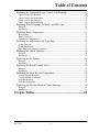
Table of Contents
Introduction .................................................................4
Service Notes.....................................................................................................4
Identification......................................................................................................5
Vehicle Towing Information .............................................................................6
Maintenance Schedule.......................................................................................7
Maintenance Record..........................................................................................8
Parts Lists ....................................................................9
Unit Assembly ...................................................................................................9
Control Arm Components ...............................................................................10
Control Arm Assemblies .................................................................................11
Steering Components ......................................................................................12
Air Spring and Shock Components.................................................................14
HCV Components (non-SHC Models Only) ..................................................15
Height Sensor Components (-SHC Models Only) ..........................................16
Sway Bar Components (-SB Models Only) ....................................................17
Disc Brake Components..................................................................................18
King Pin Components .....................................................................................19
Steering Knuckle Carrier Components ...........................................................20
Lubrication ................................................................21
Lubricant Specifications and Intervals............................................................21
General Lubrication.........................................................................................21
Ball Joints ........................................................................................................21
Rod Ends on Tie Rods Crank Rod ..................................................................22
Carrier Bearing and Kingpin ...........................................................................22
Wheel Bearings ...............................................................................................23
Troubleshooting.........................................................24
Inspection ...................................................................28
General Inspection...........................................................................................28
Inspecting the Control Arm Bushings for Wear .............................................28
Inspecting the Tie Rod Ends ...........................................................................29
Inspecting the Brake System ...........................................................................29
Brake System .................................................................................................................. 29
Inspecting the ABS Sensor and Tone Ring.....................................................30
Inspecting the Shock Absorber .......................................................................30
Inspecting the Air Spring and Height Control Valve......................................31
Air Spring Inspection...................................................................................................... 31
Height Control Valve Inspection .................................................................................... 31
Table of Contents
Inspecting the Idler Arm & Crank Arm Bearings...........................................31
Inspecting the Relay Rod Ball Joints ..............................................................32
Seal Inspection ................................................................................................................ 32
Endplay Inspection.......................................................................................................... 32
Inspecting Wheel Bearing Endplay.................................................................32
Inspecting the Knuckle Carrier Bearing and Seal ...........................................33
Inspecting the Kingpin Vertical Endplay........................................................33
Adjustments ...............................................................34
Adjusting Wheel End Play ..............................................................................34
Adjusting Suspension Ride Height .................................................................36
Adjusting Wheel Bearing Endplay..................................................................37
Adjusting the Maximum Wheel Turn Angle ..................................................38
Inspection before Alignment ...........................................................................40
Wheels and Tires............................................................................................................. 40
Front Suspension............................................................................................................. 40
Rear Axle and Suspension .............................................................................................. 40
Front Wheel Alignment...................................................................................40
Equipment ....................................................................................................................... 40
General............................................................................................................................ 41
Preparation ...................................................................................................................... 41
Adjusting the Camber Angle...........................................................................42
Eccentric Camber Adjustment ........................................................................................ 42
Bar Pin Camber Adjustment ........................................................................................... 44
Adjusting the Caster Angle .............................................................................44
Eccentric Caster Adjustment........................................................................................... 45
Adjusting the Toe-In .......................................................................................46
Repair .........................................................................48
General Procedures..........................................................................................48
Cleaning the Parts............................................................................................48
Ground or Polished Parts ................................................................................................ 48
Rough Parts..................................................................................................................... 49
Drying ............................................................................................................................. 49
Preventing Corrosion ...................................................................................................... 49
Replacing Tie Rod Ends..................................................................................49
Removal .......................................................................................................................... 49
Installation....................................................................................................................... 49
Replacing the Relay Rod Ball Joints...............................................................50
Removal .......................................................................................................................... 50
Installation....................................................................................................................... 50
Replacing the Bell Crank, Idler Arm, and Crank Arm Bearings ....................50
Removal .......................................................................................................................... 51
Installation....................................................................................................................... 51
Table of Contents
Replacing the Upper and Lower Control Arm Bushings................................51
Upper Control Arm Removal.......................................................................................... 52
Upper Control Arm Installation ...................................................................................... 52
Lower Control Arm Removal ......................................................................................... 52
Lower Control Arm Installation...................................................................................... 53
Replacing Wheel Bearings, Oil Seals, and Hub Caps.....................................53
Removal .......................................................................................................................... 54
Installation....................................................................................................................... 55
Replacing Brake Components .........................................................................57
Brake Rotors ................................................................................................................... 57
Brake Chambers.............................................................................................................. 57
Other Brake Components................................................................................................ 57
Replacing the ABS Sensor and Tone Ring .....................................................57
Sensor Removal .............................................................................................................. 57
Sensor Installation........................................................................................................... 57
Tone Ring Removal and Installation .............................................................................. 58
Replacing the Shock Absorber........................................................................58
Removal .......................................................................................................................... 58
Installation....................................................................................................................... 58
Replacing the Air Spring.................................................................................58
Removal .......................................................................................................................... 58
Installation....................................................................................................................... 58
Replacing the Height Control Valve ...............................................................59
Removal .......................................................................................................................... 59
Installation....................................................................................................................... 59
Replacing the Sway Bar and Components ......................................................59
Vertical Linkage Removal .............................................................................................. 59
Vertical Linkage Installation........................................................................................... 59
Sway Bar Removal ......................................................................................................... 59
Sway Bar Installation...................................................................................................... 59
Replacing the Steering Knuckle Carrier Bearings ..........................................60
Removal .......................................................................................................................... 60
Installation....................................................................................................................... 61
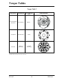
Torque Tables............................................................63
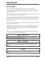
Introduction
Introduction
Service Notes
This Service Manual describes the correct service and repair procedures for the
Re yc oGra nning ® IFS1700S Independent Front Suspension model with 17,000 lbs Gross
Axle Weight Rating (GAWR). Overloading the suspension may result in adverse ride and
handling characteristics.
You must read and understand all procedures and safety precautions presented in this manual
before conducting any service work on the suspension.
Proper tools must be used to perform the maintenance and repair procedures in this manual.
Some procedures require the use of special tools for safe and correct service. Failure to use
the proper and/or special tools when required can cause personal injury and/or damage to
suspension components.
You must follow your company safety procedures and use proper safety equipment when you
service or repair the suspension.
The information contained in this manual was current at the time of printing and is subject to
change without notice or liability. Re yc oGra nning ® reserves the right to modify the
suspension and/or procedures and to change specifications at any time without notice and
without incurring obligation.
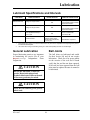
Re yc oGra nning ®
uses the following types of notices for potential safety problems and to
give information that will prevent damage to equipment.
WARNING
A warning indicates procedures that must be followed exactly. Serious personal
injury can occur if the procedure is not followed.
CAUTION
A caution indicates procedures that must be followed exactly. Damage to equipment
or suspension components and personal injury can occur if the procedure is not
followed.
NOTE
A note indicates an operation, procedure or instruction that is important for correct
service.
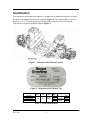
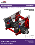
Identification
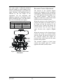
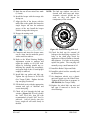
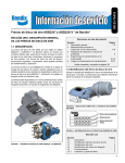
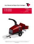
The suspension model and serial number are stamped on an aluminum tag that is riveted to
the front of the suspension sub-frame assembly (Figure 1). The serial number is used by
Re yc oGra nning ® for control purposes and should be referred to when servicing the
suspension or requesting technical support (Figure 2).
Figure 1 - Suspension Identification Location
Figure 2 - Suspension Serial Number Tag
Model
IFS1700S
IFS1700S-SB
IFS1700S-SHC
IFS1700S-SHCSB
GAWR
(lb)
17,000
Wheel
Cut
Disc
Brakes
55°
Bendix
ADB22X
Sway
Bar
No
Yes
No
Yes
Table 1 - Model Identification
Height Control
Valve
Electronic
Sensor
Dual
Single
Dual
Single
Vehicle Towing Information
If a vehicle is disabled and needs to be towed by the front end to service center, check the
OEM/Coach Builder towing procedures for the recommended method. Check with local
authorities and Department of Transportation (DOT) for permissible towing methods before
towing. Some states do not permit towing by chains and/or straps.
The preferred towing apparatus is the type that cradles the front tires. If the towing apparatus
cannot be attached to the front tires or directly to the chassis frame rails, then the suspension
sub-frame may be used for attachment.
WARNING
Attaching towing equipment to improper locations and failure to utilize OEM/Coach
Builder recommended towing methods could result in one or more of the following:
··Loss of vehicle control.
··Possible disconnection from tow vehicle.
··Damage to the suspension and/or vehicle.
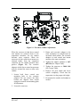
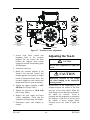
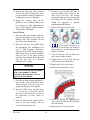
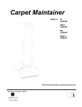
Do Not attach tow apparatus (hooks, chains, straps, etc.) to suspension upper and lower
control arms, sway bar and brackets, brake components, tie rods, steering arm assemblies, or
steering knuckle carrier assemblies (Figure 3).
Figure 3 – Improper Tow Equipment Attachment Locations
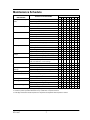
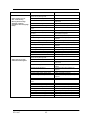
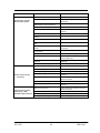
Maintenance Schedule
GENERAL
MAINTENANCE
Steering Arm Assembly Ball
Joints
Control Arm Bushings
Tie Rod Ends
Brake System
Air Springs
SERVICE TO BE PERFORMED
MILEAGE IN THOUSANDS
12
24
36
Check axial endplay
48
60
72
84
96
X2
X
Inspect for ruptured seals
X
X
X
X
X
X
X
X2
Check that cotter pin is installed
X
X
X
X
X
X
X
X2
Check bolt torque
X2
X
Inspect for control arm and mount contact
X
X
X
X
X
X
X
X2
Inspect for bushing wear
X
X
X
X
X
X
X
X2
Inspect ball socket endplay
X
X
X
X
X
X
X
X2
Check for taper connection looseness
X
X
X
X
X
X
X
X2
Check cotter pin installation
X
X
X
X
X
X
X
X2
2
Inspect Brake Pads for excessive or uneven wear
X
X
X
X
Inspect Brake Caliper for minimum free play
X
X
X
X2
Inspect for Air Leaks using soapy water solution
X
Inspect for proper clearance (1” minimum all around)
X
Check upper mount nut and lower mount bolt torque
X
Inspect for signs of chafing or wear
X
Inspect for air leaks using soapy water solution
X
Height Control Valve and
Linkage
Inspect for signs of bending, binding, or slippage
X
Inspect for air leaks using soapy water solution
X
Shock Absorbers
Check mounting nut torque
X
Inspect shocks for signs of fluid leak, broken eye
ends, loose fasteners, or worn bushings
X
X
X
X
X
X
X
X2
X
X
X
X
X
X
X2
X
X
X
X
X
X
X2
Check for wear
X
X2
Inspect vertical endplay
X
X2
Steering Arm Assembly
Bearings
Check Mounting Nut torque
X
X2
Carrier Bearings
Check axial endplay
Wheels
Check Wheel Bearing endplay
Kingpins
Inspect bearings for excessive radial play
X
X
X
X
X
X
X2
X2
X2
X
Check Wheel Nut torque1
X
3
Front Alignment
Inspect toe-in
Air Fittings and Air Lines
Inspect for air leaks using soapy water solution
X
Inspect for signs of chafing, cracking, or wear
X
Sway Bar Bushings
X
X
X
X
X
X
X
X
X
Check mounting bolt torque
X
X
X
X2
X
X
X
X
X
X
X
X
X2
X2
X
Inspect for bushing wear
X2
X
X
X
X2
1. Wheel Nuts must be re-tightened to proper torque specifications as per the vehicle or chassis manufacturer’s Owner Guide
2. Continue to perform specified maintenance every 12,000 miles or at previous interval
3. Final stage manufacturer should complete toe-in inspection and adjustment after completion of vehicle
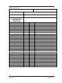
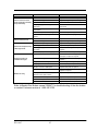
Maintenance Record
Name of Owner:
Address of Owner:
Date of Purchase:
Name and Address of Dealer:
Model of Vehicle:
Vehicle Identification Number:
Suspension Model Number:
Suspension Serial Number:
IFS1700S; IFS1700S-SB;
IFS1700S-SHC;
IFS1700S-SHCSB
Inspection and Maintenance Item
Date
Mileage
Service Performed
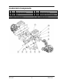
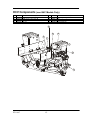
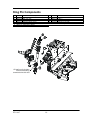
Parts Lists
Unit Assembly
Item
Part No.
1
2
3
4
5
6
7
8
711511-01
700944-01
703182-01
700245-01
705633-01
705633-02
705013-17
705013-18
Description
Sub frame Assembly
Lower Control Arm Assembly
Upper Control Arm Assembly
Boss, Eccentric
Carrier Assembly, LH
Carrier Assembly, RH
Caliper Assembly, LH
Caliper Assembly, RH
Item
Part No.
9
10
11
12
13
14
15
16
707819-01
705951-01
700178-06
700973-01
702030-01
700973-02
703915-01
706899-01
Description
Hub and Rotor Assembly
Air Spring Assembly
Shock Absorber
Tie Rod Assembly, LH
Relay Rod
Tie Rod Assembly, RH
Height Control Linkage Assembly
Height Control Arm
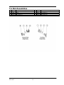
Control Arm Components
Item
Part No.
1
2
3
4
5
6
703182-01
700944-01
700245-01
8490
292
100122-P1
Description
Assembly, Upper Control Arm
Assembly, Lower Control Arm
Boss, Eccentric
Spacer
Hex Head Bolt 7/8-9 x 8.50, Gr. 8, ZN
Lock Nut 7/8-9”, Gr. C
Item
Part No.
7
8
9
10
11
12
293
701683-04
100039-P1
702516-02
168
166
Description
Socket Set Screw 10-24 x .38”
Hardened Flat Washer, 7/8”
Hex Head Bolt 3/4-10 x 2.75, Gr. 8, Zn
Hex Head Bolt 1 1/8-12 x 7.75, Gr. 8, ZY
Hardened Flat Washer, 1 1/8”
Lock Nut 1 1/8-12, Gr. C
Control Arm Assemblies
Item
1
2
Part No.
Description
703181-01 Upper Control Arm, LH & RH
700939-01 Lower Control Arm, LH & RH
Item
Part No.
3
8382
Description
Bushing
Steering Components
Item
Part No.
1
2
3
4
5
6
7
8
9
10
11
700973-01
700973-02
701924-01
700973-05
705619-01
702030-01
705620-01
167
89422312
2571
101445-P1
Description
Item
Tie Rod Assembly, LH
Tie Rod Assembly, RH
Crank Arm Assembly
Crank Rod Assembly
Bell Crank Assembly
Relay Rod
Idler Arm Assembly
Hex Head Bolt 1-14 x 6”, Gr. 8
Lock Nut 1”, Gr. C
Hardened Flat Washer 1”
Cotter Pin- 1/8 X 1 1/2
12
13
14
15
16
17
18
19
20
21
Part No.
K705382
705382-01
705382-02
705382-03
701925-01
700949-01
700951-01
K710622
8654
701378-01
6966
7348
Description
Kit, Ball Joint and Hardware
*Ball Joint (40mm)
*Slotted Nut, M20x1.5
*Cotter Pin, 1.40 x .15 Dia.
Crank Arm
Bell Crank
Idler Arm
Kit, Bearing Replacement
**Shim
**Bearing
**Snap Ring
**Spacer
*Components of Ball Joint Kit K705382
*Components of Bearing Replacement Kit K710622
Tie Rod Assemblies
Item
Part No.
1
2
3
4
103712
6632
700971-01
103736
Description
Tie Rod End, RH
Clamp
Tube, Tie Rod
Tie Rod End, LH
Item
Part No.
5
6
7
8
101445-P1
710671-01
700971-02
710671-02
Description
Cotter Pin (Not Shown)
Tie Rod End, LH
Tube, Crank Rod
Tie Rod End, RH
Air Spring and Shock Components
Item
Part No.
1
2
705951-01
700178-06
705692-01
705692-02
707357-01
263
8120382
100263-P1
276
100039-P1
89422850
3
4
5
6
7
8
9
10
Description
Item
Air Spring Assembly
Shock Assembly
Cast Lower Air Spring Mount, LH
Cast Lower Air Spring Mount, RH
Lower Shock Mount
HFW 3/8"
SLW 3/8”
HHB 3/8-16 x 1, Gr. 8, ZN
FHB 1/2-13x1.75 GR.8
HHB 3/4-10 x 2.75, Gr. 8, ZN
HFW 5/8”
11
12
13
14
15
16
17
18
19
20
Part No.
706026-01
706026-02
152
302
208
8131017
100678-P1
149
706899-01
100727-P1
700184-04
Description
Brake Line Bracket, LH
Brake Line Bracket, RH
HFW 3/4” (Used as Spacers on Forward Side)
FHB 3/8-16 x 1.25" Gr. 8 ZN
LFN 3/4-10, Gr. G, ZN
FW 3/4" .812 x 1.469 x .134, ZP
HHB 3/4-10 x 3.5, Gr. 8, ZN
HHB 5/8-18 x 3.00, Gr. 8, ZN
Height Control Arm
HHB 3/4-10 x 4.00, Gr. 8, ZN
HHB 5/8-18 x 1 3/4, Gr. 8, ZN
HCV Components (non-SHC Models Only)
Item
Part No.
1
2
3
4
5608
702606-02
100703-P1
8120392
Description
HCV, Standard
HHB 1/4-20 x 1.25”, Gr. 8, ZN
LN 1/4”
FW 1/4”
Item
Part No.
5
6
7
8
703915-01
705932-01
705967-01
705967-02
Description
Assembly, Linkage
Pin
1/4” Nylock Nut
5/16” Nylock Nut
6
1
2
4
5
3
8
7
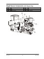
Height Sensor Components (-SHC Models Only)
Item
Part No.
1
2
3
4
702606-02
100703-P1
8120392
703915-01
Description
HHB 1/4-20 x 1.25”, Gr. 8, ZN
LN ¼”
FW ¼”
Assembly, Linkage
Item
Part No.
5
6
7
8
705378-01
705932-01
705967-01
705967-02
Description
Height Control Sensor, Electronic
Pin
1/4” Nylock Nut
5/16” Nylock Nut
6
1
5
3
4
2
7
8
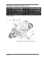
Sway Bar Components (-SB Models Only)
Item
Part No.
1
2
703124-01
703165-01
K706842
703127-03
703128-01
702895-02
702894-01
K705273
702797-01
3
4
5
6
7
Description
Sway Bar
Assembly, Mount, UCA, Sway Bar
Kit, Sway Bar Mount
*Link, UCA, Sway Bar
*Mount, UCA, Sway Bar
*Bushing, Split, Sway Bar
*Mount, D-Ring Sway Bar
Kit, Sway Bar Fasteners
**FHB 7/16-14 x 1.25, Gr. 8, ZP
* Items included with K706842
** Items included with K705273
Item
Part No.
8
9
10
11
12
13
14
15
118
102550
700144-23
8455001
307
702898-01
89422299
89422301
Description
**FW 1/2” **
**HHB 1/2-13 x 2.75, Gr. 8, Zinc
**HHB 1/2-13 x3.50, Gr. 8, Zinc
**HHB 1/2-13 x 2.00, Gr. 8, Zinc
**FHB 1/2-13 x 1.50, Gr. 8, Zinc
**Washer, Cut, Sway Bar
**LN 7/16-14, Gr. 8
**LN 1/2-13, Gr. 8, Zinc
Disc Brake Components
Item
Part No.
1
2
3
266
7328
6946
705011-01
705011-02
8223752
705051-01
705051-02
705052-01
705052-02
705017-01
705017-02
705011-21
705011-26
705011-22
705011-20
4
5
6
7
8
9
10
11
12
Description
Item
Part No.
13
14
19
20
21
22
23
24
705011-27
705084-01
705013-15
705013-16
1786
700690-04
705013-17
705013-18
705013-04
703553-02
89422308
103003
708181-01
709226-01
707819-01
4
8
Flange Head Bolt 5/16-18x.75, Gr. 5, ZC
ABS Sensor (Straight w/Lead)
ABS Sensor Spring Retainer
Steering Knuckle Assembly, LH
Steering Knuckle Assembly, RH
Hex Head Bolt ¾-16 x 2, Gr. 8, ZN
Bearing Cone - Inner
Bearing Cup - Inner
Bearing Cone - Outer
Bearing Cup - Outer
Arm, Steering, LH
Arm, Steering, RH
Castle Nut 1¼ - 12
Key
Assembly, Steering Stop
Cotter Pin 3/16 x 2-1/2
15
16
17
18
Description
ABS Sensor Bushing
Oil Seal Assembly
Torque Plate Assembly, LH
Torque Plate Assembly, RH
Hub Cap Gasket
Hex Head Bolt M20x1.5-50 Gr. 10.9
Caliper Assembly, LH
Caliper Assembly, RH
Brake Pads (Set of 4)
HFW M20 ZN
Lock Nut ¾-16 x .75, Gr. G, PH
HFW 3/4”
Nut, Spindle, Pro-Torq
Hub Cap
Hub and Rotor Assembly
20 21
11
15
5
14
2
3
13
12
9
10
17
19
6
24
7
23
1
22
16
18
King Pin Components
Item
Part No.
1
2
3
4
5
6
705011-07
705011-08
705011-09
705011-14
705011-15
705011-16
Description
Shim, .005” thick
Shim, .010” thick
Shim, .020” thick
Assembly, Bearing, Thrust
Bolt, King Pin Cap
Grease Fitting, Straight
6
5
7
8
2
1
3
10
9
4
11
Oil seal is on the bottom
of the thrust bearing
towards the knuckle side
Item
Part No.
7
8
9
10
11
705011-17
705011-18
705011-19
705315-01
705316-01
Description
Cap, King Pin
O-Ring
King Pin
Draw Key, (Long 3.80)
Nut, Draw Key
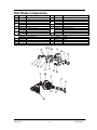
Steering Knuckle Carrier Components
Item
1
2
3
4
5
6
Part No.
Description
705632-01 Machining, Carrier, LH
705632-02 Machining, Carrier, RH
Upper Bar Pin
702621-01
Lower Bar Pin
702836-01 Seal
702619-01 Outer Collar
702623-01 Shim, .004
Item
Part No.
7
8
9
10
11
12
13
702834-01
702622-01
702835-01
702623-02
702618-01
702620-01
7352
Description
Bearing Cone
Spacer
Bearing Cup
Shim, .010
Split Collar
Retaining Clip
Grease Zerk, Hydraulic Shutoff
6 10
8
5
11 12
4
1
9
2
7
3
13
Left Hand Steering Knuckle Carrier Shown
Lubrication
Lubrication
Lubricant Specifications and Intervals
COMPONENT
SERVICE INTERVAL
CHANGE INTERVAL
LUBRICANT SPECIFICATION
Multi-Purpose Chassis Grease
Rod Ends of Tie
Rods & Crank Rod
Whichever comes first: Every oil
change or every 6 months
N/A
Kingpin
Whichever comes first: Every oil
change or every 6 months
Premium Multi-Purpose Chassis
Grease NLGI Grade 2
Multi-Purpose Chassis Grease
N/A
Premium Multi-Purpose Chassis
Grease NLGI Grade 2
Mobillith AW2
Amoco L Industrial 861
Exxon Ronex MP
Carrier Bearings2
Wheel End
Whichever comes first: 50,000
miles (80,000 kilometers) or
once a year
1000 miles (1600 kilometers)
Check fluid level
N/A
Whichever comes first: Seals
replaced, brakes relined,
100,000 miles (160,000 km),
or once a year
Gear Oil
SAE 80W/90 or equivalent
1.
Moly-disulfide type grease is not recommended since it may lower friction capabilities in the adjusting clutch parts of
the automatic slack adjuster.
2.
Use caution when using an automatic grease gun or seals could possibly be blown out and damaged.
General Lubrication
Ball Joints
Proper lubrication practices are important
in maximizing the service life of your
Re yc oGra nning ®
Independent Front
Suspension.
The ball joints are lubricated and sealed
for their service life and do not require
lubrication. Check for oil or grease marks
on the exterior of the seal and if found
verify that the seal has not been ruptured.
If the seal has been ruptured then the ball
joint must be replaced because it cannot be
re-lubricated.
CAUTION
Do not mix lubricants of different
grades. Do not mix mineral and
synthetic lubricants. Different brands
of the same grade may be mixed.
CAUTION
Never mix oil bath and grease packed
wheel ends.
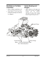
Rod Ends on Tie Rods
Crank Rod
Carrier Bearing and
Kingpin
1. Review lubricant specification and
interval requirements before servicing.
1. Apply lubricant to both upper and
lower carrier bearings and kingpin
bushings
until
new
lubricant
discharges from the carrier bearing
seals and in between the steering
knuckle kingpin housing and carrier.
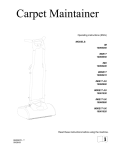
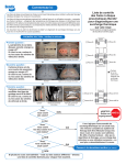
2. Apply lubricant to grease fitting until
new lubricant discharges from the dust
boot (Figure 4).
Grease Fittings
Grease Fittings
Grease Fittings
Figure 4 – Location of Lubrication Fittings
Note: Left side only shown
3. Check the hub cap for external oil
marks. The vent plug will normally
weep a small amount of oil. Oil marks
in other locations should be addressed
by replacing the hub cap seal, window
gasket, or tightening the pipe fill plug.
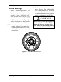
Wheel Bearings
1. Review lubricant specification and
interval requirements before servicing.
2. Check oil level through hub cap
window. If level is below the “add”
level line then remove the pipe plug
and fill with recommended oil until
“full” level is achieved. (Figure 5).
Add oil slowly since the heavy weight
oil will settle slowly in the hub.
CAUTION
Do not remove or twist the red plug on
the front of the hub cap. This will
damage the hub cap, and cause oil to
leak. Add oil only thru the pipe plug or
warranty will be void.
NOTE: The hub cap window can only be
cleaned with mild soap and water.
Aromatic solvents should not be used,
as they will impair the transparency
of the window.
Figure 5 - Wheel Bearing Oil Level
Troubleshooting
Troubleshooting
SYMPTOMS
Tires wear out quickly or have
uneven tire tread wear
Note: Wear pattern will indicate
possible cause(s). Consult
tire manufacturer for
guidance.
POSSIBLE CAUSES
REMEDIES
Tires have incorrect pressure
Put specified air pressure in tires.
Tires out of balance
Balance or replace tires
Incorrect toe-in setting
Adjust toe-in to specified setting
Incorrect ride height
Adjust ride height to specified setting
Incorrect rear axle alignment
Align rear axle to specified thrust angle
Incorrect steering arm geometry
Adjust tie rod lengths as required
Improper (mismatched) tires and wheels
Install correct tire and wheel combination
Improper oversized tires
Install correct tire and wheel combination
Vehicle is difficult to steer
Tires not uniform
Install correct tire and wheel combination.
Note: Engine must be running for
power steering to be active
and able to provide
steering assist.
Tires have incorrect pressure
Put specified air pressure in tires
Incorrect steering arm geometry
Adjust tie rod lengths as required
Steering arm assemblies binding
Check steering arm assembly bearings and
lubricate as required
Steering arm assembly ball joints binding
Inspect ball joints for wear and replace as
required
Tie rod ends binding
Inspect tie rod ends for wear and lubricate as
required
Kingpin binding
Inspect, lubricate, and repair as required.
Steering column linkage binding
Align or adjust as required
Steering miter box binding
Check steering miter box and repair or
replace as required
Steering gear valve binding
Inspect, repair or replace as required
Steering wheel to column interference
Align or adjust as required
Power steering pump fluid level low
and/or possible leak in system
Add fluid, tighten connections and correct as
required
Power steering pump pressure and flow
below specification
Conduct pump flow and relief pressure tests
and adjust, repair or replace as required
Air in power steering system
Add fluid, tighten connections and bleed
system
Contaminated or incorrect fluid
Replace with correctly specified fluid
Obstruction with steering gear pitman arm
or within hydraulic lines
Inspect, remove obstruction(s) and repair or
replace as required
Obstruction within wheelhouse
Inspect, remove obstruction(s) as required
Excessive internal steering gear leakage
Inspect, repair or replace as required
SYMPTOMS
Vehicle wanders side-toside…loose steering
Steering wheel has large
amplitude, rotational
oscillations when hitting large
bumps
POSSIBLE CAUSES
REMEDIES
Vehicle overloaded or unevenly loaded
driver side to passenger side
Improper (mismatched) tires and wheels
Tires have incorrect pressure
Check wheel loads and correct as required
Incorrect toe-in setting
Incorrect wheel caster setting
Tie rod end connection loose or ball stud
worn
Steering arm assembly mounts loose
Steering arm assembly ball joints binding
or worn
Kingpin worn
Wheel bearings out of adjustment
Adjust toe-in to specified setting
Adjust wheel caster to specified setting
Inspect ball stud connections and wear
Loose steering gear mounting
Loose pitman arm
Steering column linkage worn
Steering gear adjustment
Steering column misaligned
Worn knuckle carrier bearings
Loose knuckle carrier mounting bolts
Loose Wheel Nuts
Vehicle pulls to one side
without the brakes applied.
Vehicle overloaded or unevenly loaded
driver side to passenger side
Improper (mismatched) tires and wheels
Tires have incorrect pressure
Unequal ride height side to side
Improper brake adjustment
Incorrect rear axle alignment
Incorrect caster and/or camber setting
Wheel bearings out of adjustment
Loose steering gear mounting
Tie rod end connection loose or ball stud
worn
Bent spindle or steering arm
Frame or underbody out of alignment
Incorrect toe-in setting
Mis-aligned belts in radial tires
Steering gear valve binding
Steering gear not centered
Excessive internal steering gear leakage
Excessive water puddling on road
Install correct tire and wheel combination
Put correct air pressure in tires based on
wheel load
Check and tighten to specification
Inspect ball joints for wear or contamination
and replace as required
Check and replace as required
Check wheel bearing end play and adjust as
required
Check mounting and secure as required
Check pitman arm and tighten as required
Check for wear and repair or replace as
required
Check and adjust to specification
Realign steering column as required
Check, adjust, or replace as required
Check and tighten as required
Check and tighten to specification
Check wheel loads and correct as required
Install correct tire and wheel combination
Put correct air pressure in tires based on
wheel load
Inspect ride height and adjust to specified
setting
Inspect and adjust slack adjusters as
required
Align rear axle to specified thrust angle
Check and adjust as required
Check wheel bearing end play and adjust as
required
Check mounting and secure as required
Inspect ball stud connections and wear
Inspect and replace as required
Inspect and correct as required
Adjust toe-in to specified setting
Check and replace as required
Inspect, repair or replace as required
Inspect and adjust as required
Inspect, repair or replace as required
Avoid water puddles on road
SYMPTOMS
Vehicle pulls to one side
with the brakes applied
Vehicle rolls side to side
excessively
Front tires lock up during
hard braking or ABS
malfunction light remains lit
POSSIBLE CAUSES
REMEDIES
Grease, oil or dirt on brake pads
Replace brake pads as required
Brake pads are glazed
Deglaze brake pads by burnishing or replace
as required
Brake pads are not a balanced set,
different friction codes or pad brand
Replace brake pads as required
Loose or broken brake pads
Replace brake pads as required
Brake rotor warped
Re-machine or replace brake rotor as
required
Defective brake rotor
Inspect for defects and replace as required
Brake air chamber clevis pin or camshaft
binding
Check and lubricate as required
Uneven brake adjustment side to side
Adjust Caliper as required
Different brake air chamber size side to
side
Replace with same size brake air chambers
Brake chambers air pressure uneven side
to side
Check side-to-side air pressure and correct
as required
Rear axle brakes misadjusted or
contaminated
Check, adjust, or replace as required
ABS system malfunction
Check ABS system for proper function
Air leak or obstruction in air brake lines
Check fittings with soapy water solution and
remove obstructions
Brake air chamber air leak or diaphragm
damaged
Check chamber for air leak and damaged
diaphragm
Excessive water puddling on road
Avoid water puddles on road
Front and/or rear shock absorbers worn
Replace shock absorbers as required
Shock mounting loose
Check and tighten as required
Shock eye bushings worn
Check and replace as required
Sway bar bushings worn
Check sway bar bushings and replace as
required
Sway bar mounting brackets loose
Check sway bar mounting brackets and
tighten as required
Control arm pivot bushings worn
Inspect and replace as required
Internal leak in height control valve
Check height control valve and replace as
required
ABS sensor malfunction
Inspect ABS sensor installation and replace
sensor as required
ABS CPU or system malfunction
Check and repair or replace as required
ABS sensor electrical connection faulty
Check ABS sensor connection and lead wire
Tone ring on hub damaged
Check for damage and replace as required
SYMPTOMS
POSSIBLE CAUSES
Front shock absorbers worn
Vehicle ride is too harsh
and/or suspension contacts
stops excessively
Vehicle ride is too soft
Vehicle has unequal turning
radius right to left
Suspension does not
maintain ride height
Brakes are noisy
REMEDIES
Replace shock absorbers as required
Incorrect ride height
Adjust ride height to specified setting
Vehicle overloaded
Check wheel loads and correct as required
Air spring supply lines leaking or
obstructed
Check air line connections and remove
obstructions
Vehicle system air pressure below
specification
Check air pressure and correct as required
Rebound bumper worn or missing
Check and replace as required
Jounce bumper in air spring worn or
broken
Check and replace air spring as required
Front shock absorbers worn
Replace shock absorbers as required
Incorrect ride height
Adjust ride height to specified setting
Incorrect steering arm geometry
Adjust tie rod lengths as required
Steering gear not centered
Inspect and adjust as required
Steering gear poppet valves set
incorrectly
Check wheel turn angles and adjust as
required
Tie rod clamps positioned improperly
Check orientation and adjust as required
Air leak
Check connections with soapy water solution
and repair or replace as required
Internal leak in height control valve
Check height control valve and replace as
required
Height control valve linkage loose
Check and tighten linkage as required
Air spring chafed or worn
Check air spring and Replace as required
Grease, oil or dirt on brake pads
Replace brake pads as required
Brake pads are glazed
Deglaze brake pads by burnishing or
Replace as required
Brake pads are not a balanced set,
different friction codes or brand
Replace brake pads as required
Loose or broken brake pads
Replace brake pads as required
Brake Rotor Warped
Re-machine or Replace as required
Defective Brake Rotor
Inspect for defects and Replace as required
Refer to Bendix Disc Brakes manual Y006471 for troubleshooting of the disc brakes
or contact Customer service at 1-800-247-2725.
Inspection
Inspection
General Inspection
WARNING
Perform a thorough visual inspection of
the suspension to ensure proper assembly
and to identify broken parts and loose
fasteners each time the vehicle suspension
is serviced. Do the following during an
inspection.
Wheel Alignment - Follow the guidelines
in the Front Wheel Alignment section for
wheel alignment inspection intervals.
Check wheel alignment if excessive
steering effort, vehicle wander, or
abnormal tire wear is evident.
Fasteners - Check that all the fasteners are
tightened to the proper tightening torque.
Use a calibrated torque wrench to check
torque.
Wear and Damage - Inspect components
of the suspension for wear and damage.
Look for bent or broken components.
Replace
all
worn
or
damaged
components.
Operation - Check that all components
move freely through the complete wheel
turning arc.
Never work under a vehicle supported
by only a jack(s). Jacks can slip or fall
over and cause serious personal injury.
Always use safety stands. Do not place
jacks or safety stands under the lower
control arms to support the vehicle.
Lower control arms are not stationary
components and could move allowing
the vehicle drop causing serious
personal injury.
The vehicle may be supported on safety
stands by the suspension sub-frame or
chassis frame for inspections that require
removal of the wheel and tires or deflation
of the air springs. Always secure the
vehicle by setting the parking brake and
block the drive wheels to prevent vehicle
movement before inspections.
Inspecting the Control
Arm Bushings for Wear
NOTE
CAUTION
It is recommended that the bushings in
all of the control arms be replaced at
the same time if one is found worn.
Reyco Granning LLC recommends
replacing any damaged or out-ofspecification components.
Reconditioning or field repairs of front
suspension components is prohibited.
Some cast components are heattreated. These components as well as
other non-heat treated castings cannot
be bent, welded, heated, or repaired in
any way without reducing the strength
or life of the component thus voiding
the warranty. Only genuine
Re yc oGra nning ® replacement
components are allowed.
1. Check clearance between each control
arm and sub-frame bushing mount.
Look for contact pattern as evidence of
bushing wear. Replace worn bushings
in both control arm housings as
needed.
2. Check for bushing bulging between the
control arm and sub-frame mount or
presence of small rubber particles near
sub-frame bushing mount.
3. Check that the control arm mounting
bolts are tight. Recommended torque
is 465-485 ft-lb for lower control arms
and 950-1050 ft-lb for upper control
arms (See Torque Table). A loose
joint will result in wear between the
bushing inner sleeve and sub-frame
mount.
4. Measure the axial movement with a
scale. If the movement is greater than
1/8 inch (3mm) replace the tie rod end
immediately. If the socket moves but
the movement is less than 1/8 inch
(3mm) then the tie rod end should be
replaced before 1/8” (3mm) movement
occurs.
5. Check dust boot for damage. Replace
as needed.
Inspecting the Tie Rod
Ends
6. Check tie
(Figure 6)
rod
clamp
orientation
WARNING
Do not use a wrench or other object to
apply leverage when inspecting tie rod
end sockets. Applying leverage can
yield incorrect results and damage
components. Component damage can
lead to the loss of steering control.
1. With the engine on, lightly rock the
steering wheel and have an assistant
observe any looseness in the two
mating tapers or any movement of the
stud nut at both ends of the tie rod.
(Figure 6). If looseness is found in
either place go to step 2, otherwise
skip to step 3.
Figure 6 - Tie Rod
Inspecting the Brake
System
2. Remove the tie rod end ball stud from
the taper mount and visually inspect
both. If either of the mating tapers
shows distortion or wear, then both
components must be replaced. Torque
Tie Rod Castle Nuts to 90-100 ft-lb
(See Torque Table).
.'"5/0")
The suspension system is equipped with
Bendix ADB22X air brakes. Refer to
Bendix service data publication SD-237541 for inspection and service
procedures.
3. With the engine off and the wheels
steered straight ahead, grab the tie rod
near its end and try to move the socket
in a direction parallel to the ball stud
axis (Figure 6). Be sure to only apply
hand pressure to the tie rod.
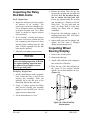
Inspecting the ABS
Sensor and Tone Ring
10. Repeat Step 3. If voltage output is less
than 0.8V AC then replace the ABS
sensor.
NOTE: Check voltage output of new sensor.
1. The wheels and may need to be
removed to ease inspection of tone
ring and sensor.
2. Disconnect the ABS sensor lead from
the chassis connector.
3. The ABS sensor test will require a
voltmeter that can measure AC voltage
on a 0-10V scale.
4. Connect the voltmeter to the connector
pins of the ABS sensor lead.
5. Set the voltmeter scale to millivolts
and the voltage source to AC volts.
Figure 7 - ABS Sensor and Tone Ring Gap
Inspecting the Shock
Absorber
6. Rotate the wheel hub by hand and
record the voltage output from the
ABS sensor. A minimum output of
0.8V AC is normal.
1. Check shock absorbers for oil leakage,
bent components, missing or broken
components, excessive corrosion, or
worn bushings. Replace shock
absorbers if any of the above items is
present.
7. If the minimum voltage output is not
achieved, check lead wire connections
and repeat Step 3. Otherwise, if the
minimum voltage output is not
achieved after repeating Step 3 then go
to Step 5.
8. Check physical gap between the sensor
and tone ring (Figure 7).
The
maximum allowable gap is .027 inch.
If the gap is greater than .027 inch,
press on the wire lead end of the
sensor and push the sensor into contact
with the tone ring. Check that the
ABS spring retainer and bushing are
not unseated. Re-seat components as
needed.
9. Inspect the tone ring on the hub for
physical
damage
and
proper
installation onto the hub. The tone ring
should have a maximum run out of
.008 inch relative to the hub/spindle
centerline.
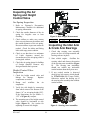
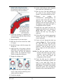
Inspecting the Air
Spring and Height
Control Valve
“B”
%.,.%*#*/," 0%+*
“A”
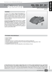
1. Refer to Firestone’s Preventative
Maintenance Checklist for additional
air spring information.
2. Check the outside diameter of the air
spring for irregular wear or heat
checking.
Figure 8 - Ride Height Measurement
Unit
IFS1700S
3. Check airlines to make sure contact
does not exist between the airlines and
the outside diameter of the air spring.
Re-secure airlines to prevent contact as
needed. Check for airline and fitting
leaks with soapy water solution.
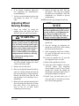
1. Check that steering arm assembly
pivots are free of foreign material and
bearing seals are in place.
2. Start vehicle engine. Oscillate the
steering wheel and observe the motion
of the steering arm assemblies (Figure
9).
The steering arm assemblies
should not exhibit any noticeable
conical motion about their pivot axes.
5. Check the air spring piston for buildup
of foreign material. Remove any
foreign material that is present.
"%#$0+*0.+((2"
*/," 0%+*
3. If any conical motion is observed
check pivot bolt torque which should
be 575-625 ft-lb (See Torque Table).
Otherwise, replace the bearing set of
the steering arm assembly that exhibits
conical motion.
1. Check the height control valve and
linkage for damage.
Replace
components as needed.
re-inflate
the
Air Spring “B”
9.25”
Inspecting the Idler Arm
& Crank Arm Bearings
4. Check to see that there is a minimum
of 1-inch clearance around the
circumference of the air spring while it
is energized with air.
2. Dump and
suspension.
Ride Height “A”
6.61”
air
3. Verify the ride height by measuring
from wheel center to the bottom of the
frame (“A”) or air spring height (“B”).
If the dimensions are not within +/.125” of (Figure 8), readjust.
4. The actuation arm of the height control
valve should be horizontal at ride
height (Figure 8). See section for
adjusting to correct ride height.
Figure 9 - Steering Arm Assemblies
4. Release the clamp. Place the pry bar
between the steering arm assembly and
the Relay Rod. Do not allow the pry
bar to contact the ball joint seal.
Firmly pry upward using the steering
arm assembly as a fulcrum to lift the
Relay Rod. The pry load must not
cause the Relay Rod to rotate thus
causing the Relay Rod to change
orientation.
Inspecting the Relay
Rod Ball Joints
"(*/," 0%+*
1. Inspect the ball joint seal outer surface
for presence of oil “wetting”. The
entire outer seal surface should be dry.
Use a mechanics mirror and flashlight
to inspect the entire seal. Use a blunt
object as needed to inspect between
seal convolutes.
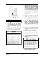
5. Record the dial indicator reading. A
reading greater than .040” will require
ball joint replacement.
2. If oil “wetting” is found, then inspect
the entire wet area to confirm the seal
has a rupture(s) and oil source is from
internal grease leaking from the ball
joint. If seal is ruptured, then the ball
joint must be replaced.
6. Inspect ball joint seal for damage and
replace the ball joint if damaged
during measurement process.
Inspecting Wheel
Bearing Endplay
3. Skip ball joint endplay measurement.
1. Remove the tire and wheel.
NOTE
2. Remove the hub cap.
Care must be taken to not damage ball
joint seals during inspection. Seals that
are ruptured during inspection must
be replaced. Do not apply excessive
force to pry ball joints.
3. Attach a dial indicator with a magnetic
base to the face of the hub.
4. Place the tip of the dial indicator on
the center of the steering knuckle
spindle. Set the dial indicator on zero.
(Figure 10).
*!,(5*/," 0%+*
1. Install a dial indicator with a magnetic
base so that the base is fixed to the
steering arm assembly. Place the
indicator tip on the flat area of the
Relay Rod adjacent the castle nut.
2. Using a C-clamp, squeeze the Relay
Rod and the steering arm assembly
together to seat the ball joint. Do not
apply excessive clamp load.
3. Set the dial indicator on “zero”.
Figure 10 - Wheel End Play
Measurement
2. Place the magnetic base of a dial
indicator on the knuckle carrier and
position the tip of the dial on top of the
king pin bearing cap such that vertical
movement can be measured.
NOTE
Do not push/pull at the top and the
bottom of the hub. Pushing or pulling
at the top and the bottom will not yield
a true measurement of the endplay.
3. Place a portable jack and a suitable
block (one with clearance for the
grease fitting) under the lower king pin
grease cap area.
5. Measure
the
endplay
by
simultaneously pushing/pulling on
opposite sides of the hub while
observing the dial indicator. The
endplay is the total travel observed. If
the endplay is not within .001-.005”,
see the section on adjusting the wheel
bearing endplay.
4. Set the dial indicator to “0” (zero).
5. Raise the jack until the dial indicator
shows the end of vertical travel.
Measure and record the dial indicator
reading. Vertical inspection clearance
must be .006-.012 inches.
Inspecting the Knuckle
Carrier Bearing and
Seal
6. If the steering knuckles binds or less
than .001 inch endplay is measured,
remove shims from the shim pack. See
repair section for kingpin.
1. Inspect the seals for damage.
7. If the vertical endplay measurement is
more than .012 inches, then install
shims. See repair section for kingpin.
2. Place the magnetic base of a dial
indicator on the knuckle carrier and
position the tip of the dial on the end
of the bar pin such that axial
movement can be measured.
3. Set the dial indicator to “0” (zero).
4. Place a pry bar between the control
arm and carrier and pry to measure
axial movement of the bar pin. Do not
pry on seal. Measure and record the
dial indicator reading.
5. If the axial endplay is more than “0”
inch, then replace the carrier bearings.
See repair section on knuckle carrier.
Inspecting the Kingpin
Vertical Endplay
1. Turn the tire straight ahead.
Adjustments
Adjustments
4. Rotate the hub such that the drain hole
faces downward and drain the oil from
hub cavity. Wait a few minutes for
most of the oil to drain before
continuing to the next step.
Adjusting Wheel End
Play
WARNING
Never work under a vehicle supported
by only a jack(s). Jacks can slip or fall
over and cause serious personal injury.
Always use safety stands. Do not place
jacks or safety stands under the lower
control arms to support the vehicle.
Lower control arms are not stationary
components and could move allowing
the vehicle drop causing serious
personal injury.
5. Remove the hub cap bolts, hub cap,
and gasket. Take care not to damage
the gasket for re-installation. Place the
components in a location to prevent
contamination.
NOTE: Solvents may damage the hub cap
window.
NOTE
When removing or installing the inner
and outer spindle nuts, use the correct
wrench sockets to avoid damaging the
nuts. Do not use impact driver to
tighten inner and outer nuts. Only use
a torque wrench to tighten the nuts.
WARNING
Failure to follow this instruction could
cause the wheel to come off and cause
bodily injury. The PRO-TORQ®
Spindle Nut is sold as an assembly with
the keeper in place. DO NOT attempt
to place the nut on the spindle or
tighten or loosen the nut on the spindle
while the keeper is locked inside the
nut. Doing so may deform the keeper
and allow the nut to unthread during
operation.
6. Remove the keeper from the nut.
7. A, B, C Use a small screwdriver to
carefully pry the keeper arm from the
undercut groove on each side until the
keeper is released.
1. Secure the vehicle by setting the
parking brake and block the drive
wheels to prevent vehicle movement.
8. Seat the bearing, with the hub rotor
only, using a torque wrench.
2. Raise the vehicle until the front wheels
are off the ground. Support the raised
vehicle with safety stands.
9. Tighten the nut to 200 ft-lb. Spin the
wheel at least one full rotation.
3. Place an oil drip tub beneath the hub to
catch oil. Rotate the hub such that the
hub cap drain plug is facing upwards.
Remove the drain plug from the hub
cap and place it in a container for reinstallation.
10. Repeat step #9 two more times.
11. Back the nut off until it is loose.
20. Attach a dial indicator with a magnetic
base to the face of the hub rotor.
21. Place the tip of the dial indicator on
the center of the steering knuckle
spindle. Set the dial indicator on zero.
22. Measure
the
endplay
by
simultaneously pushing/pulling on
opposite sides of the hub rotor while
observing the dial indicator. The
endplay is the total travel observed. If
the endplay is not within .001-.005”, a
readjustment will be required.
23. Install hub cap gasket and hub cap.
Tighten the cap screws in sequence to
20-30 ft-lb (See Torque Table).
Replace the hub cap vent plug if
removed.
12. Adjust the bearing by tightening the
nut to 100 ft-lb. Spin the wheel at least
one full rotation.
24. Fill the hub cavity with the appropriate
amount and type of lubricant and
secure drain plug.
13. Repeat step #12 two more times.
25. Check oil level through the hub cap
window (Figure 5). If level is below
the “add” level line, then fill with
recommended oil until “full” level is
achieved. Add oil slowly since the
heavy weight oil will settle slowly in
the hub.
14. Back the nut off one raised face mark
(1/4 turn).
15. Install the keeper with the orange side
facing out.
16. Align the flat of the keeper with the
milled flat on the spindle and insert the
single keeper tab into the undercut
groove of the nut. Install the keeper
with the orange side facing out.
17. Engage the mating teeth.
NOTE: The hub cap window can only be
cleaned with mild soap and water.
Aromatic solvents should not be
used, as they will impair the
transparency of the window.
26. Check the hub cap for external oil
leakage at the drain plug or gasket. For
leaks at the drain plug check for
application of thread sealant to threads
and tightness. For leaks at the gasket,
replace the gasket. The vent plug will
normally weep a small amount of oil.
18. Compress and insert the keeper arms,
one at a time, into the undercut groove
with a small screwdriver.
19. Verify the end play
Adjusting Suspension
Ride Height
CAUTION
Adjusting the ride height can cause the
front end to raise or lower
unexpectedly due to vertical
movements at the connection of the
vertical link and the horizontal arm of
the height control valve.
The height control valve (HCV) and
linkage should be checked regularly for
proper
clearance,
operation
and
adjustment.
NOTE
1. Park the vehicle on a level surface.
Improperly adjusted ride height will
result in incorrect wheel alignment
measurements and may result in
abnormal tire wear. Check the ride
height prior to front suspension
alignment.
2. Exhaust or “dump” and re-inflate the air
suspension. Allow the Suspension to
settle.
3. Check ride height of rear suspension:
A: On vehicles with front suspension
equipped with (2) height control
valves, check and adjust the rear
suspension first.
The ride height of the front suspension is
the distance from the bottom of the chassis
frame rail to the center of the wheel
spindle. An alternate measurement may be
taken as the height of the air spring
(Figure 11).
B: On vehicles with front suspension
equipped with a single height control
valve, check and adjust the rear
suspension after finish adjusting the
front.
“B”
4. Measure either the wheel center to
bottom of frame (“A”) or air spring
height (“B”). If the dimensions are not
within ±1/8” of measurements in
Figure 11, adjust as follows.
“A”
A: Loosen the height control valve
linkage stud retaining nuts.
B: Raise or lower the L-shaped linkage
stud as necessary.
Figure 11 – Measurement at Ride
Height
Unit
IFS1700S
Ride Height “A”
6.61”
C: Tighten the retaining nuts.
Air Spring “B”
9.25”
NOTE: It is recommended that the upper
and lower studs be positioned
parallel to each other. Torque to 812 ft-lb.
Properly adjusted ride height results in
correct suspension travel and alignment.
The ride height should not be adjusted to
adjust chassis rake angle.
5. After adjusting the length, it is
recommended to dump and re-inflate
the air suspension to obtain the ride
height. Allow the suspension to settle.
6. If not already completed, adjust the
rear suspension per manufacturer’s
recommendations.
7. Verify at each axle that the side-to-side
ride heights are within .25” of each
other.
Adjusting Wheel
Bearing Endplay
6. Remove the hub cap bolts, hub cap,
and gasket. Take care not to damage
the gasket for re-installation. Place the
components in a location to prevent
contamination.
NOTE: Solvents may damage the hub cap
window.
NOTE
When removing or installing the inner
and outer spindle nuts, use the correct
wrench sockets to avoid damaging the
nuts. Do not use impact driver to
tighten inner and outer nuts. Only use
a torque wrench to tighten the nuts.
1. Secure the vehicle by setting the
parking brake and block the drive
wheels to prevent vehicle movement.
WARNING
7. Remove the cotter pin and loosen the
spindle nut.
Never work under a vehicle supported
by only a jack(s). Jacks can slip or fall
over and cause serious personal injury.
Always use safety stands. Do not place
jacks or safety stands under the lower
control arms to support the vehicle.
Lower control arms are not stationary
components and could move allowing
the vehicle drop causing serious
personal injury.
8. Seat the bearings by tightening the
spindle nut to 200 ft-lb. while rotating
the wheel in both directions.
9. After torquing the castle nut to 200 ftlb, rotate the hub and rotor ten (10)
complete revolutions.
10. Loosen the spindle nut 1/2 turn and
then tighten the nut to 50 ft-lb.
2. Raise the vehicle until the front wheels
are off the ground. Support the raised
vehicle with safety stands.
11. Back off the spindle nut 1/8 turn.
12. Verify that wheel endplay is between
.001-.005 inches. (See inspecting
wheel endplay section). If not, loosen
spindle nut, re-index the spindle nut
accordingly, and repeat Steps 9 thru 12
until proper endplay is achieved.
3. Remove the tire and wheel.
4. Place an oil drip tub beneath the hub to
catch oil. Rotate the hub such that the
hub cap drain plug is facing upwards.
Remove the drain plug from the hub
cap and place it in a container for reinstallation.
13. Install cotter pin and bend over, if
cotter pin hole is not lined up, loosen
nut to first locking position.
5. Rotate the hub such that the drain hole
faces downward and drain the oil from
hub cavity. Wait a few minutes for
most of the oil to drain before
continuing to the next step.
CAUTION
CAUTION
Never tighten the spindle nut to align
the cotter pin with hole in locking
washer. This can pre-load the
bearings and cause premature bearing
failure.
Do not adjust maximum wheel turn
angle greater than 55°. Misadjustment of the wheel turn angle can
cause damage to steering system
components.
14. Install hub cap gasket and hub cap.
Tighten the cap screws to 20-30 ft-lb
(See Torque Table). Replace the hub
cap vent plug if removed.
15. Fill the hub cavity with the appropriate
amount and type of lubricant and
secure drain plug.
The turn angle may require adjustment if
the front tires rub against the frame,
suspension, body, or the steering gear has
been serviced or replaced.
Use an
alignment machine to check the wheel turn
angle. See the measurement procedure of
the alignment machine manufacturer.
16. Check oil level through the hub cap
window. (Figure 5). If level is below
the “add” level line, then fill with
recommended oil until “full” level is
achieved. Add oil slowly since the
heavy weight oil will settle slowly in
the hub.
The steering stop bolt on the steering
knuckle controls the maximum turn angle.
If the stop bolt is missing, bent, or broken;
replace the stop bolt(s) or jam nut(s) and
follow the procedure below for
adjustment.
Inspect other suspension
components for damage.
NOTE: The hub cap window can only be
cleaned with mild soap and water.
Aromatic solvents should not be
used, as they will impair the
transparency of the window.
CAUTION
In power steering systems, the
hydraulic pressure should relieve or
“drop off” when the steered wheels
approach the steering stops in either
direction. If the pressure does not
relieve, the components of the front
suspension may be damaged.
17. Check the hub cap for external oil
leakage at the drain plug or gasket. For
leaks at the drain plug check for
application of thread sealant to threads
and tightness. For leaks at the gasket,
replace the gasket. The vent plug will
normally weep a small amount of oil.
If the steering stop bolts are adjusted to
reduce wheel turn angle, the steering gear
poppet valves will require readjustment. If
the poppets are not re-adjusted properly,
then the steering gear will not reduce
power assist properly and steering
components will be damaged. Refer to
TRW’s TAS Steering Gear Service
Manual for readjusting the poppets.
Adjusting the Maximum
Wheel Turn Angle
3. Check that the steering gear is centered
and the tires are steered straight ahead
with equal toe-in side to side. If either
of these two conditions is not met, then
adjust toe-in first before centering the
steering gear. See Adjusting the ToeIn Section and refer to Spartan chassis
service guidelines for centering the
steering gear.
4. Check that the lengths of the outer tie
rods are equal to each other within 1/8
inch. If not, adjust lengths according
to the adjusting the toe-in section
before adjusting the steering stops.
Figure 12 - Steering Stop Bolt
Unit
IFS1700S
5. Turn the steering wheel until the
steering stop bolt contacts the knuckle
carrier or the steering wheel stops
turning. Measure the turn angle of the
wheel on the same side as the direction
of turn.
Steering Stop Length “A”
1.38”
1. Drive the front tires on a suitable
device that allows the front wheels to
turn and measures the wheel turn
angle.
6. If the wheel turn angle differs from
Spartan chassis guidelines then adjust
as follows.
2. Secure the vehicle by setting the
parking brake and block the drive
wheels to prevent vehicle movement.
7. Loosen the jam nut on the stop bolt.
NOTE
8. Turn the stop bolt until the specified
wheel turn angle is achieved and the
bolt head contacts the knuckle carrier.
Unequal toe-in side to side or an outof-center steering gear can result in
unequal turn angles and steering pull
while steering straight ahead. The
Crank Rod length may be adjusted to
attain steering gear on center condition
while maintaining equal toe-in side to
side. Do not adjust the length of the
Crank Rod or Tie Rods to center the
steering wheel. This can cause the
steering gear to become off center.
9. Tighten the jam nut to 50-75 ft-lb (See
Torque Table).
CAUTION
After readjusting the steering stop(s)
check that the steering poppets are
reset properly and that the front tires
do not contact the frame, suspension,
or body. Also check that other
components are not abnormally
contacting one another.
10. Repeat checking and adjustment for
turning the opposite direction.
".4("*!1/,"*/%+*
Inspection before
Alignment
Front tire wear and incorrect steering can
be caused by the rear axle and/or
suspension.
See the General Inspection section and
check the following before conducting
front wheel alignment measurements.
1. Check that all fasteners are tightened
to the specified torque.
$""(/*!%."/
2. Check the suspension ride height and
adjust as needed to specified height.
1. Check that the front tires are inflated to
the appropriate pressure based on the
tire loading.
3. Check that all connection joints
between the suspension and axle are
secure.
2. Check that the front tires are the same
size and type.
4. Check for worn suspension bushings
or damaged suspension components.
3. Check that all the Wheel Nuts are
tightened to the specified torque of
450-500 ft-lb (See Torque Table).
4. Check that the wheel
assemblies are balanced.
and
5. Check that the rear axle is correctly
aligned.
tire
6. Check that the frame is not bent.
.+*01/,"*/%+*
7. Refer
to
any
additional
recommendations and specifications
from the manufacturer of the chassis
on rear axles and suspensions.
1. Check that all fasteners are tightened
to the specified torque.
2. Check the suspension ride height and
adjust as needed to the specified
height.
NOTE
Total vehicle alignment is
recommended when aligning the front
suspension.
3. Check for worn ball joints, tie rod
ends, steering arm assembly bearings,
control arm bushings, knuckle carrier
bearings, and damaged suspension
components.
Replace
worn
components as needed.
Front Wheel Alignment
-1%,)"*0
4. Check for loose ball joint and tie rod
end tapered connections, tie rod end
jam nuts, steering arm assembly
mounts, and chassis steering system
components. Inspect connections for
wear and replace as needed. Tighten
connections as needed.
Re yc oGra nning ®
recommends
that
suitable alignment equipment be used to
measure
the
wheel
alignment
characteristics: camber, caster, and toe-in.
The alignment equipment must be
properly
calibrated
for
accurate
measurements. Only qualified personnel
should conduct the wheel alignment
measurements.
5. Check the wheel bearing adjustment
and adjust as needed.
6. Inspect the shock absorbers for wear
and damage.
"*".(
NOTE
The overall toe-in of the front wheels
should be checked every 24,000 miles or 2
years. When the vehicle does not steer
correctly or the front tires develop an
abnormal tire wear pattern, the camber,
caster, and toe-in should be measured and
adjusted as needed. Toe-in typically has
the largest effect on tire wear.
An out-of-center steering gear can
result in unequal wheel turn angles.
The steering gear should remain
centered during toe-in adjustment. Do
not adjust the length of the Crank Rod
or Tie Rods to center the steering
wheel. This can cause the steering gear
to become off center.
The maximum wheel turn angle should be
checked and adjusted as needed.
3. Check that the steering gear is centered
when the tires are steered straight
ahead (i.e. equal toe-in side to side).
Center the steering gear according to
Spartan’s guidelines.
Eccentric adapters are installed in the
lower control arm mounts. The purpose of
the adapters is to provide additional
adjustment of camber and caster to
minimize vehicle drifts or pulls to one side
of the road.
4. Measure and record the individual
wheel camber, caster, and toe-in of the
front suspension. Also measure and
record the cross camber cross caster,
and overall toe-in.
The bar pins of the knuckle carrier bearing
marked with a “B” may also be used to
provide additional camber adjustment.
5. If adjustment to camber and caster is
required then follow the steps below.
Otherwise, go to the “Adjusting the
Toe-In” section to adjust the toe-in as
needed.
.",.0%+*
1. Follow the alignment equipment
manufacturer’s
procedures
for
preparing the vehicle for front and rear
wheel alignment measurements.
WARNING
2. Secure the vehicle by setting the
parking brake and block the drive
wheels to prevent vehicle movement.
Never work under a vehicle supported
by only a jack(s). Jacks can slip or fall
over and cause serious personal injury.
Always use safety stands. Do not place
jacks or safety stands under the lower
control arms to support the vehicle.
Lower control arms are not stationary
components and could move allowing
the vehicle drop causing serious
personal injury.
6. Raise the vehicle until the front wheels
are off the ground. Support the raised
vehicle with safety stands.
Adjusting the Camber
Angle
Positive
Camber
Nominal Camber Values-Degrees
Unloaded
Loaded
Left
+1/4°(±1/4°)
+1/4°(±1/4°)
Right
+1/4°(±1/4°)
+1/4°(±1/4°)
Negative
Camber
Figure 13 – Camber Angle
CAUTION
Do not alter components to adjust the
camber.
Camber is the angle of the wheel with
respect to the ground as viewed from the
front or rear of the vehicle (Figure 13).
Camber is positive when the distance
between centers of the front wheels at the
top is greater than the distance at the
ground.
Wheel Camber Angle is affected by the
ride height of the suspension. If the ride
height is set too high, then the camber
measurement will be more positive. See
the inspecting and adjusting suspension
ride height sections before measuring
camber.
The table below lists the
recommended camber angles.
"*0.% )".!&1/0)"*0
The setscrew in the eccentric adapter
denotes the orientation of the eccentricity
of the adapter. When the setscrew is in the
12 o’clock position, then the adapter is in
the “neutral” position. There are two
adapters at each lower control arm mount
and they must be oriented the same.
Neutral Position
Neutral Position
Positive Camber
Positive Camber
Negative Camber
Negative Camber
FORWARD
Figure 14 – Eccentric Camber Adjustment
3. Rotate each eccentric adapter to the
same orientation as needed based on
measured wheel camber. The eccentric
adapters at each control arm mount
must have the same orientation.
When the setscrews in both lower control
arm mounts are oriented closer to the
suspension centerline, the tire camber
becomes more negative. When the
setscrews in both control arm mounts are
oriented farther from the suspension
centerline, the tire camber becomes more
positive (Figure 14). The eccentric
adapters at both lower control arm mounts
must be oriented the same to affect only
camber.
4. Tighten the adapter locknuts to 465485 ft-lb (See Torque Table).
5. Tighten the setscrews to 30-40 ft-lb
(See Torque Table).
6. Remove the jack stands and lower
vehicle completely. Check that the
suspension is at the proper ride height.
1. Loosen both lower control arm
mounting bolts at the eccentric
adapters. Do not remove the bolts
because the adapters must remain
engaged in control arm mounting plate
for adjustment.
7. Re-measure the camber and readjust as
needed.
2. Loosen the setscrews.
.%*)".!&1/0)"*0
4. Lower the jack to align the bar pin
with the control arm. Apply Loctite
#271 to mounting bolt threads and
tighten to 350-370 ft-lb (See Torque
Table).
The lower bar pin of the knuckle carrier
bearing marked with a “B” on the end is
configured such that it can be re-oriented
to provide camber adjustment. Lower bar
pins are factory installed with the “B”
located closest to the lower control arm.
The wheel camber becomes more positive
when the lower bar pin is re-oriented such
that the “B” is located farthest from the
lower control arm.
Adjusting the Caster
Angle
Positive
Caster
Negative
Caster
1. Place a portable jack under the tire to
secure and support it.
CAUTION
Do not remove both upper and lower
knuckle carrier mounting bolts at the
same time. The knuckle carrier must
be secured and supported properly if
both upper and lower mounting bolts
are removed.
Figure 15 – Caster Angle
CAUTION
NOTE
Do not adjust the suspension ride
height or alter components to adjust
the caster.
Lower control arm may move
downward due to the internal gas
charge in the shock absorber. A
portable jack may be needed to align
the lower control arm with the knuckle
carrier bar pin.
The caster angle is the angle between a
vertical axis and the axis defined by the
king pin when viewed from the side of the
vehicle. When the king pin axis appears
rotated clockwise relative to the vertical
axis, then the caster is positive. Positive
caster creates a self-aligning moment to
stabilize the vehicle when driving straight
ahead (Figure 15).
2. Remove the bottom knuckle carrier
mounting bolts from the lower control
arm. Heat may need to be applied to
the control arm to loosen the thread
adhesive. The control arm temperature
must not exceed 300°F. Do not apply
heat directly to the bar pin or mounting
bolts.
3. Raise the jack to separate the bar pin
from the control arm and re-orient it.
"*0.% /0".!&1/0)"*0
The caster angle is indirectly measured
from the change in wheel camber as the
wheel is turned through a prescribed turn
angle. Therefore, the calculated caster is
affected by the ride height of the
suspension. See the inspecting and
adjusting suspension ride height sections
before measuring caster. The table below
lists the recommended caster angles.
The setscrew in the eccentric adapter
denotes the orientation of the eccentricity
of the adapter. When the setscrew is in the
12 o’clock position, then the adapter is in
the “neutral” position. There are two
adapters at each lower control arm mount
and they must be oriented the same.
When the setscrews in the forward lower
control arm mount are oriented closer to
the frame rail and the setscrews in the
rearward lower control arm mount are
oriented farther from the frame rail, the
caster becomes more negative (Figure
17).
Nominal Caster Values-Degrees
Unloaded
Loaded
Left
+3°(±1/2°)
+3°(±1/2°)
Right
+3°(±1/2°)
+3°(±1/2°)
Positive
Caster
When the setscrews in the forward lower
control arm mount are oriented farther
from the frame rail and the setscrews in
the rearward control arm mount are
oriented closer to the frame rail, the caster
becomes more positive.
Negative
Caster
Lower
Control Arm
The eccentric adapters at both lower
control arm mounts must be oriented
opposite each other to affect caster.
Rear
Eccentrics
Front
Eccentrics
FORWARD
Figure 16 – Lower Control Arm
Movement
Neutral Position
Neutral Position
Positive Caster
Positive Caster
A
B
Negative Caster
Negative Caster
VIEW A-A
LH Front Eccentric View
Scale 1:2
A
B
VIEW B-B
LH Rear Eccentric View
Scale 1:2
FORWARD
Figure 17 – Eccentric Caster Adjustment
1. Loosen both lower control arm
mounting bolts at the eccentric
adapters. Do not remove the bolts
because the adapters must remain
engaged in control arm mounting plate
for adjustment.
Adjusting the Toe-In
CAUTION
Do not alter components to adjust the
toe-in.
2. Loosen the setscrews.
3. Rotate the eccentric adapters at the
forward and rearward control arm
mounts opposite one another as needed
based on measured wheel caster. The
eccentric adapters at each control arm
mount must have the same orientation.
CAUTION
Improperly oriented tie rod clamps
can cause binding in the suspension
steering system.
4. Tighten the adapter locknuts to 465485 ft-lb (See Torque Table).
Wheel toe-in is the relationship of the
distance between the centers of the front
and rear of the front wheels. When the
front distance is less than the rear distance,
the wheels are “toed-in”. Toe-in is
designed into the suspension to counteract
the tendency of the tires to toe-out when
the vehicle is driven straight ahead.
Incorrect toe-in can result in rapid tire
wear.
5. Tighten the setscrews to 30-40 in-lb
(See Torque Table).
6. Remove the jack stands and lower
vehicle completely. Check that the
suspension is at the proper ride height.
7. Re-measure caster and readjust as
needed.
1. Measure the length of the outer tie
rods. Reference length is 17 inches.
2. If the lengths of the outer tie rods are
not within 1/8 inch of each other, then
adjust their lengths such that they are
within 1/8 inch of each other. Loosen
the tie rod clamps on each end of the
tie rod and turn the center tube to
change the length.
3. Adjust the length of both outer tie rods
equally such that the toe-in on each
side is 1/16” ± 1/32” and the overall
toe-in is 1/8” ± 1/16”. Tighten tie rod
clamp nuts to 50-60 ft-lb (See Torque
Table). Refer to Figure 6 for tie rod
clamp orientation.
Repairs
Repair
General Procedures
WARNING
Repair or reconditioning of front
suspension components is not allowed.
Components that are damaged or worn
must be replaced. Several major
components are heat treated and tempered.
Never work under a vehicle supported
by only a jack(s). Jacks can slip or fall
over and cause serious personal injury.
Always use safety stands. Do not place
jacks or safety stands under the lower
control arms to support the vehicle.
Lower control arms are not stationary
components and could move allowing
the vehicle drop causing serious
personal injury.
WARNING
The components cannot be bent,
welded, heated altered, or repaired in
any way without reducing the strength
or life of the component and voiding
the warranty.
The vehicle may be supported on safety
stands by the suspension sub-frame or
chassis frame for repairs that require
removal of the wheel and tires or deflation
of the air springs. Always secure the
vehicle by setting the parking brake and
block the drive wheels to prevent vehicle
movement before performing repairs.
The following operations are prohibited on
front suspension components.
1. Welding of or to the steering knuckles,
control arms, steering arm assemblies,
knuckle carrier, tie rod assemblies, the
brakes, the hubs, and the brake rotors.
Cleaning the Parts
2. Hot or cold bending of the steering
knuckles, control arms, steering arm
assemblies, knuckle carrier, tie rod
assemblies, ball joints, and the subframe except control arm and steering
arm assembly mounts which may be
cold bent to facilitate bushing and
bearing replacement.
WARNING
If you use cleaning solvents, hot
solution tanks or alkaline solutions
incorrectly, serious personal injury can
occur. To prevent injury, follow the
instructions
supplied
by
the
manufacturer. Do NOT use gasoline to
clean parts. Gasoline can explode.
3. Drilling out control arm and steering
arm assembly mounting holes and ball
stud tapered holes.
.+1*!+.+(%/$"!.0/
4. Spray welding of bearing diameters on
the steering knuckle spindle, steering
arm assembly bores and pivot tube.
Spray welding of ball studs or tapered
holes for the ball joint and tie rod ends.
Use a cleaning solvent to clean ground or
polished parts and surfaces. DO NOT
clean ground or polished parts with hot
solution tank or with water, steam or
alkaline solutions. These solutions will
cause corrosion of the parts.
5. Milling or machining of any
component except that control arm
bushing bores may be honed to remove
any burrs.
+1#$.0/
4. Inspect the tie rod end ball stud and
mating component tapered hole(s).
Replace components with worn
tapered hole(s). If the grease seal is
damaged during removal, replace it
before installation.
Rough parts can be cleaned with the
ground and polished parts. Rough parts
also can be cleaned in hot solution tanks
with a weak alkaline solution. Parts should
remain in the hot solution tanks until they
are completely cleaned.
*/0((0%+*
.5%*#
1. Clean the mating component tapered
hole(s) of any contamination. Insert
the tie rod end ball stud into the
tapered hole and secure it with the
castle nut.
Parts must be dried immediately after
cleaning. Dry all parts with clean paper or
rags, or compressed air. Do not dry
bearings by spinning with compressed air.
."2"*0%*#+..+/%+*
CAUTION
Apply light oil to cleaned and dried parts
that are not damaged and are to be
immediately assembled. Do NOT apply
oil to the brake pads or the brake rotors. If
the parts are to be stored, apply a good
corrosion preventative to all surfaces and
place them inside special paper or
containers that prevent corrosion. Do
NOT apply corrosion preventative to the
brake pads or the brake rotors.
Tighten the castle nuts to the specified
torque. If the castle nuts are not
tightened to the specified torque, the
parts will be damaged and serious
personal injury may occur.
2. Tighten the castle nut to 90-100 ft-lb
(See Torque Table).
3. Install the cotter pins. If necessary,
tighten the castle nut to align the hole
in the ball stud and slots in the castle
nut. Do not loosen the castle nut to
install the cotter pin.
Replacing Tie Rod Ends
")+2(
4. Lubricate tie rod end as needed.
1. Remove the cotter pins from the tie rod
end ball stud(s).
2. Remove the castle nuts from the tie rod
end ball stud(s).
CAUTION
Do not strike the component mating
taper directly with a steel hammer.
Parts can break and cause serious
personal injury. Wear eye protection.
3. Disconnect the tie rod end ball stud
from the mating component tapered
hole using a suitable tool.
Replacing the Relay
Rod Ball Joints
5. Inspect the ball joint stud and Relay
Rod tapered hole(s). Replace Relay
Rod if tapered hole(s) is worn.
The thread-in mount type ball joints are
installed with a thread adhesive and may
require the threads to be warmed to ease
removal. If heat is applied to the ball joint
threads, the steering arm assembly
temperature must not exceed 300°F and
the heat should be applied at the bottom of
the ball joint base only. Applying heat to
the ball joint will damage the ball joint by
destroying its internal components as well
as the external seal permanently,
degrading the lubricant, and restricting
ball stud movement.
*/0((0%+*
1. Clean the threaded hole in steering arm
assembly of any contamination.
2. Apply thread adhesive Loctite #242 to
the ball joint base threads and thread it
into the steering arm assembly by
hand.
3. Tighten the base of the ball joint to
325-375 ft-lb (See Torque Table).
4. Clean the Relay Rod tapered hole(s) of
any contamination. Insert the ball joint
stud into the tapered hole and secure it
with the castle nut.
It is recommended that the appropriate
tools be used to remove the ball stud taper
from the Relay Rod and to remove the ball
joint base from the steering arm assembly.
CAUTION
")+2(
Tighten the castle nuts to the specified
torque. If the castle nuts are not
tightened to the specified torque, the
parts will be damaged and serious
personal injury may occur.
1. Remove the cotter pins from the ball
joint ball stud(s).
2. Remove the castle nuts from the ball
joint ball stud(s).
5. Tighten the castle nut to 155-175 ft-lb
(See Torque Table).
CAUTION
6. Install the cotter pins. If necessary,
tighten the castle nut to align the hole
in the ball stud and slots in the castle
nut. Do not loosen the castle nut to
install the cotter pin.
Do not strike the component mating
taper directly with a steel hammer.
Parts can break and cause serious
personal injury. Wear eye protection.
Replacing the Bell
Crank, Idler Arm, and
Crank Arm Bearings
3. Disconnect the ball joint ball stud from
the Relay Rod tapered hole using a
suitable tool.
4. Secure the steering arm assembly and
remove the ball joint using a ball joint
spanner wrench or similar device on
the base. Steering arm assembly may
be removed to facilitate ball joint
removal. See the steering arm
assembly replacement section as
needed.
Replace the bell crank, idler, and crank
steering arm bearings in sets. The
replacement bearings should be installed
by pressing on the outer raceway only.
Pressing on the inner raceway will damage
the bearing.
The inner grease cavity of the steering arm
assemblies should be cleaned when the
bearings are replaced.
ring is seated against the bottom inner
race. Do not use a steel hammer to
install the sleeve because bearing
raceways can be damaged.
")+2(
8. Install upper retaining ring. Reseat
lower retaining ring against the lower
inner race as needed.
1. Follow the procedures for removal of
the Relay Rod from the ball joint in the
bell crank and idler arm.
9. Determine the number of shims needed
by stacking the shims and placing the
stack between the upper retaining ring
and inner race until a snug fit is
achieved. Remove one shim from the
stack and this is the number of shims
needed. A maximum of six shims may
be used.
2. Follow the procedures for removal of
tie rod ends for the crank arm.
3. Remove the pivot bolts that mount the
idler arm and bell crank. Remove
them from the sub-frame.
4. Remove the retaining rings from the
pivot sleeve and remove the sleeve. A
rubber or brass hammer may be used
to remove the sleeve. Retain shims.
10. Remove the upper retaining ring,
install the shims determined in step 9
onto the inner sleeve at upper inner
race, and re-install the upper retaining
ring. Check that upper retaining ring is
properly seated in the groove of the
inner sleeve.
5. Support the steering arm assembly
bearing housing and press the bearing
out of each end.
*/0((0%+*
11. Place the steering arm assembly in its
mount and install the pivot bolt.
Tighten the pivot bolt lock nut to 575625 ft-lb (See Torque Table).
1. Clean out the steering arm assembly
grease cavity.
2. Inspect steering arm assembly bearing
housing bores and remove burrs by
honing. Replace steering arm assembly
if the bore is damaged.
3. Pack the steering
bearing with grease.
arm
12. Follow the procedures for installation
of the Relay Rod or tie rod.
Replacing the Upper
and Lower Control Arm
Bushings
assembly
4. Support the steering arm assembly
bearing housing and press the bearing
into each end. The seal side of the
bearing should face out.
The sub-frame control arm mounts may
require widening to accommodate
replacement bushings. A suitable jack may
be used to increase the width of the control
arm mounts by cold bending. Care must be
taken to not exceed 5.00” width after
widening. The control arm mounts should
be inspected for damage.
5. Inspect the pivot sleeve and remove
burrs with emery cloth.
6. Install one retaining ring onto pivot
sleeve.
7. Insert the pivot sleeve into the lower
bearing. Use a rubber mallet or similar
tool to drive the inner sleeve into the
bearings such that the bottom-retaining
Both control arm bushings and mounting
hardware except eccentric adapters must
be replaced in a control arm when
bushings are serviced. It is recommended
to replace the control arm bushings and
mounting fasteners in all of the control
arms at the same time.
3. Disconnect sway bar connector at
sway bar if so equipped with a sway
bar.
4. Loosen and remove control arm
mounting locknuts.
The control arm housings must be
properly supported during bushing
removal. The bores of the control arm
housings may be honed to remove any
burrs.
5. Support control arm and remove
control arm mounting bolts. Remove
the control arm.
6. Remove the sway bar bracket and
linkage from the control arm and retain
for installation.
CAUTION
7. Press the bushings out of the housings.
Support the housing properly.
Use of a cutting torch to remove
control arm bolts will permanently
damage control arm bushings and can
result in damage to sub-frame.
,,".+*0.+(.)*/0((0%+*
1. Inspect the housing bores and remove
any burrs in the housing bores by
honing.
It is recommended that the wheel and tire
be
removed
to
provide
proper
accessibility. Disconnect the vertical
height control valve linkage from the
horizontal arm to prevent unintentional
inflation of the air spring.
2. Press the bushings into the housings
using a suitable tool to apply pressure
to only the outer metal of the bushing.
Support the housing properly.
3. Re-install the sway bar bracket and
linkage if removed.
,,".+*0.+(.)")+2(
1. Place a portable jack under the knuckle
carrier to secure and support it.
4. Place the control arm in its mount
location. Install the control arm
mounting hardware and tighten snugly.
CAUTION
5. Orient the control arm at suspension
ride height and tighten the bolts to
950-1050 ft-lb (See Torque Table).
Do not remove both upper and lower
knuckle carrier mounting bolts at the
same time unless the knuckle carrier is
properly secured.
6. Reconnect the sway bar linkage.
Tighten mounting bolt to 75-85 ft-lb
(See Torque Table).
2. Remove knuckle carrier mounting
bolts from the control arm. Heat may
need to be applied to the control arm to
loosen the thread adhesive. The control
arm temperature must not exceed
300°F. Do not apply heat directly to
the bar pin or mounting bolts.
7. Apply Loctite #271 to mounting bolt
threads and tighten to 350-370 ft-lb
(See Torque Table).
+3".+*0.+(.)")+2(
1. Place a portable jack under the knuckle
carrier to secure and support it.
9. Press the bushings out of the housings.
Support the housing properly.
CAUTION
+3".+*0.+(.)*/0((0%+*
Do not remove both upper and lower
knuckle carrier mounting bolts at the
same time unless the knuckle carrier is
properly secured.
1. Inspect the housing bores and remove
any burrs in the housing bores by
honing.
2. Press the bushings into the housings
using a suitable tool to apply pressure
to only the outer metal of the bushing.
Support the housing properly.
NOTE
Lower control arm may move
downward due to the internal gas
charge in the shock absorber. A
portable jack may be needed to align
the lower control arm with the knuckle
carrier bar pin.
3. Install the spacer tubes in bushings.
4. Place the control arm in its mount
location. Install the control arm
eccentric adapters and mounting
hardware and tighten snugly. Orient
the eccentric adapters the same as
before removal.
2. Remove knuckle carrier mounting
bolts from the control arm. Heat may
need to be applied to the control arm to
loosen the thread adhesive. The control
arm temperature must not exceed
300°F. Do not apply heat directly to
the bar pin or mounting bolts.
5. Orient the control arm at suspension
ride height and tighten the bolts to
465-485 ft-lb (See Torque Table).
6. Note orientation of bar pin in carrier
bearing. Lower the jack to align the
bar pin with the control arm.
3. Note orientation of lower bar pin in
carrier bearing. Raise the jack as
needed to separate the bar pin from the
control arm.
7. Apply Loctite #271 to mounting bolt
threads and tighten to 350-370 ft-lb
(See Torque Table).
4. Remove and retain the lower shock bar
pin mounting hardware. Shock will
extend due to internal gas charge.
Rotate bar pin to provide clearance
with mounting bracket.
8. Compress shock absorber and connect
the lower control arm to the lower
shock bracket using the mounting
hardware. Tighten the nuts to 30-40
ft-lb (See Torque Table).
5. Note orientation of eccentric adapters
for installation.
Replacing Wheel
Bearings, Oil Seals, and
Hub Caps
6. Loosen and remove control arm
mounting locknuts.
7. Support control arm and remove
control arm mounting bolts. Retain
eccentric adapters for installation.
Remove the control arm.
If the Wheel Nuts have chrome covers,
remove them with special pliers equipped
with plastic non-marring jaws. Place them
in a container to prevent damage or loss.
8. Remove spacer tubes from bushings
and retain for installation.
On aluminum wheels, place a plastic antiscuff guard over the Wheel Nuts and
loosen the Wheel Nuts. On steel wheels,
remove the wheel hub cap nuts if present
and the wheel hub cap before loosening
the Wheel Nuts. Place the wheel hub cap
in safe location to prevent damage. Place
the wheel and/or wheel hub cap nuts in a
container to prevent contamination or loss.
NOTE
When removing or installing the outer
spindle nut, use the correct wrench
sockets to avoid damaging the nuts. Do
not use impact driver to tighten outer
nut. Only use a torque wrench to
tighten the nuts.
5. Remove the keeper from the nut.
Remove the wheel and tire assembly and
place it aside. Mark the tire to ensure it
can be identified for installation on same
side as removed. Remove the brake rotor
assembly and place it aside. Mark the rotor
assembly to ensure it can be identified for
installation on same side as removed.
")+2(
6. A, B, C Use a small screwdriver to
carefully pry the keeper arm from the
undercut groove on each side until the
keeper is released.
1. Place an oil drip tub beneath the hub to
catch oil. Rotate the hub such that the
hub cap drain plug is facing upwards.
Remove the drain plug from the hub
cap and place it in a container for reinstallation.
7. Remove the retaining nut
8. Tug sharply on the hub to unseat the
outer bearing without completely
removing the hub. Wipe up any oil
spilled on the brake assembly as
quickly and completely as possible.
Remove the outer bearing and place it
in
a
container
to
prevent
contamination.
2. Rotate the hub such that the drain hole
faces downward and drain the oil from
hub cavity. Wait a few minutes for
most of the oil to drain before
continuing to the next step.
3. Remove the Brake Caliper.
4. Remove the hub cap bolts, hub cap,
and gasket. Take care not to damage
the gasket for re-installation. Place the
components in a location to prevent
contamination.
9. Remove the hub from the spindle and
place it on the floor with its stud side
facing downwards. Protect the wheel
studs from damage. Wipe the excess
oil off spindle with a clean shop towel
to prevent oil dripping onto the brake
assembly.
NOTE: Hub cap window may be damaged by
solvents.
10. Remove the hub seal and discard it.
Remove the wear ring from the spindle
and discard it.
11. Inspect the inner cup (outer bearing
race for the inner bearing) and outer
cup in the hub for damage. Replace the
bearing cups if worn or damaged.
6. Pre-lubed outer bearing and place it
onto the spindle until it seats on the
outer cup in the hub. The bearing
retaining washer may be used to guide
the bearing onto the spindle. The hub
should be supported to prevent
misalignment and binding.
12. Inspect the bearing areas on the
spindle for wear or damage. Burrs may
be removed by light application of
emery cloth. Replace steering knuckle
if the spindle is damaged.
7. Remove the keeper from the nut.
*/0((0%+*
1. Place the hub seal assembly with axle
ring onto the spindle so the words “Oil
Bearing Side” face outboard. Do not
place the seal in the hub bore.
2. Drive the seal onto the spindle using
the appropriate seal installation tool
and a 3-5lb hammer. (Reference
Stemco P/N 0155220) The wear ring is
fully seated when it is square and flush
with the face of the inner bearing
shoulder of the spindle. Reseat the seal
onto the wear ring if it becomes
dislodged after seating.
8. A, B, C Use a small screwdriver to
carefully pry the keeper arm from the
undercut groove on each side until the
keeper is released.
9. Seat the bearing, with the hub rotor
only, using a torque wrench.
10. Tighten the nut to 200 ft-lb. Spin the
wheel at least one full rotation.
11. Repeat step #9 two more times.
NOTE
12. Back the nut off until it is loose.
Do not drive bearings onto the spindle
with a steel hammer or similar
instrument. Bearing inner race is a
tight slip fit with spindle.
3. Pre-lube the inner bearing and place it
onto spindle with small end of taper
facing outward. Seat the inner race
against the shoulder of the spindle.
4. Press the ABS sensor outward about
¼”. Do not use a sharp tool on lead
wire end of the sensor. See section for
the inspection of ABS sensor as
needed.
13. Adjust the bearing by tightening the
nut to 100 ft-lb. Spin the wheel at least
one full rotation.
5. Place the hub onto the spindle until it
seats on the inner bearing. Do not
“ram” the hub onto the seal.
14. Repeat step #12 two more times
15. Back the nut off one raised face mark
(1/4 turn)
16. Install the keeper with the orange side
facing out.
NOTE: The hub cap window can only be
cleaned with mild soap and water.
Aromatic solvents should not be
used, as they will impair the
transparency of the window.
17. Align the flat of the keeper with the
milled flat on the spindle and insert the
single keeper tab into the undercut
groove of the nut. Install the keeper
with the orange side facing out.
18. Engage the mating teeth
Figure 18 - Wheel Bearing Oil Level
19. Compress and insert the keeper arms,
one at a time, into the undercut groove
with a small screwdriver.
24. Check the hub cap for external oil
leakage at the drain plug or gasket. For
leaks at the drain plug check for
application of thread sealant to threads
and tightness. For leaks at the gasket,
replace the gasket. The vent plug will
normally weep a small amount of oil.
20. Refer to the Wheel Bearing Endplay
Adjustment section to measure and
adjust the endplay to .001-.005 inch.
Adjust by loosening spindle nut, reindexing the spindle nut accordingly,
and repeat Steps 8 thru 19 until proper
endplay is achieved.
25. Install the Brake Caliper and Pads.
26. Install the wheel and tire assembly and
the Wheel Nuts.
21. Install hub cap gasket and hub cap.
Tighten the cap screws to 20-30 ft-lb
(See Torque Table). Replace the hub
cap vent plug if removed.
27. On aluminum wheels, use a plastic
anti-scuff guard over the Wheel Nuts.
Tighten the Wheel Nuts in sequence to
450-500 ft-lb (See Torque Table).
22. Fill the hub cavity with the appropriate
amount and type of lubricant and
secure drain plug.
28. Replace the wheel hub cap nuts and
hub caps if removed to service the
wheel bearings.
23. Check oil level through the hub cap
window. (Figure 18). If level is below
the “add” level line, then fill with
recommended oil until “full” level is
achieved. Add oil slowly since the
heavy weight oil will settle slowly in
the hub.
3. Remove tie straps that secure the
sensor lead wire and disconnect the
sensor lead wire from the chassis wire
harness.
Replacing Brake
Components
.'" +0+./
"*/+.*/0((0%+*
The brake rotor should be replaced if they
are damaged or exceed the rotor
manufacturers recommended minimum
thickness or run-out specification. Refer
to Brake Rotor manufacturer guidelines
for inspection and specifications.
1. Check that the sensor bushing is
properly seated in the steering knuckle
and the sensor spring retainer is seated
properly in the sensor bushing.
2. Press the sensor into the steering
knuckle until the sensor end contacts
the tone ring.
.'"$)"./
The brake air chambers should be replaced
if damaged or malfunctioning. Refer to
manufacturer guidelines for correct
function of the brake air chambers.
3. Connect a volt meter to the connector
pins of the sensor lead wire. Set the
volt meter to read AC voltage on a
scale of 0-10V.
0$"..'"+),+*"*0/
4. Spin the hub by hand and read the
voltage output of the sensor. A
minimum reading of 0.8V AC is
normal. Skip to step 8 if minimum
reading is obtained.
The brake pads should be replaced when
they are worn beyond the manufacturer’s
limits. Refer to the brake manufacturers
guidelines for servicing the brakes.
5. If the minimum reading is not obtained
then check the volt meter connection
and proximity of the sensor and tone
ring. The air gap between the sensor
and tone ring should not exceed .027”.
Repeat step 4.
Replacing the ABS
Sensor and Tone Ring
The anti-lock brake system (ABS) of the
vehicle should be diagnosed by a qualified
technician before the anti-lock brake
sensor or the tone ring is replaced.
Replacement parts must be equivalent to
the vehicle manufacturers to ensure proper
function of the anti-lock brake system.
The anti-lock brake sensor and tone ring
cannot be repaired and must be replaced if
damaged or malfunctioning.
6. If the minimum reading is not
obtained, check the tone ring for
damage and its installation. The tone
ring should have a maximum run out
of .008”. Replace as needed and
repeat step 4.
7. If the minimum reading is still not
obtained, then replace the sensor and
repeat the installation procedure.
"*/+.")+2(
1. Remove the Brake Caliper to provide
access to sensor.
8. Route and secure the sensor lead wire
the same as the removed sensor.
2. Press sensor out of steering knuckle.
Do not pull sensor out by its lead wire.
9. Connect the sensor lead wire to the
chassis. Secure wire lead to prevent
damage during suspension movement.
+*"%*#")+2(*!
*/0((0%+*
Replacing the Air
Spring
Follow the hub manufacturer’s guidelines
for removal and installation of the tone
ring.
The correct air spring must be installed.
The use of a substitute air spring is not
allowed and may cause unequal load
sharing between the air springs and cause
adverse ride and handling characteristics.
Replacing the Shock
Absorber
")+2(
CAUTION
1. Deflate the air spring by disconnecting
one end of the vertical HCV linkage
from the horizontal arm. Rotate the
horizontal HCV arm downward and
secure it in place.
The shock absorber is gas pressurized
and must not be punctured or be
subjected to excessive heat which can
result in serious personal injury. The
shock will expand to its full extended
length if not restrained.
2. Disconnect the airline at the air spring
inlet port and remove the connection
fitting from the inlet port.
")+2(
3. Remove the bolts and washers from
the upper air spring mount studs. Note
location of bolts and washers.
1. Remove the lower shock thru bolt
mounting hardware and retain for
installation. Do not remove the lower
shock mount bracket from the lower
control arm.
4. Remove the bolts that secure the air
spring to the lower air spring mount.
*/0((0%+*
2. Remove
upper
shock
bushing
mounting hardware and retain for
installation.
Note location and
quantity of washers and spacers.
1. Attach air spring to upper air spring
mount. Note that the shorter bolt is
located towards the front. Tighten
mounting hardware snugly.
*/0((0%+*
2. Attach air spring to lower air spring
mount. Tighten lower mounting bolts
to 20-30 ft-lb (See Torque Table).
1. Loosely attach upper shock bushing to
sub-frame with mounting hardware
(spacers on forward side of shock).
3. Tighten the upper mounting bolts to
15-20 ft-lb (See Torque Table).
2. Position shock in suspension such that
the thru bolt is connected to the lower
shock mounting bracket tabs.
4. Apply Permatex or equivalent thread
sealant to the threads of the air
connection fitting and install the
fitting.
3. Tighten lower thru mounting bolt and
nut to 170-190 ft-lb (See Torque
Table). Tighten lower shock bracket
mounting bolts to 30-40 ft-lb (See
Torque Table).
5. Connect the airline to the fitting.
6. Inflate the air spring by un-securing
the HCV horizontal arm and
reconnecting the vertical linkage to it.
4. Tighten upper mounting nut to 170190 ft-lb (See Torque Table).
7. Check the airline and fitting for air
leaks.
4. Connect the vertical linkage to the
horizontal arm.
Replacing the Height
Control Valve
5. Recharge system with air and check
for air leaks.
6. Check the ride height and adjust per
section on adjusting the ride height as
needed.
The correct height control valve (HCV)
must be installed. The use of a substitute
HCV is not allowed and may cause
unequal load sharing between the air
springs and cause adverse ride and
handling characteristics.
Replacing the Sway Bar
and Components
It is recommended that the sway bar
mounting bushings and the vertical
linkages be replaced all at the same time.
")+2(
1. Drain the air from the supply reservoir
on the chassis connected to the front
suspension.
".0% (%*'#"")+2(
1. Disconnect sway vertical linkage at
upper control arm bracket on both
sides. Retain hardware for installation.
2. Disconnect the vertical HCV linkage
from the horizontal arm.
3. Mark airlines and connections for reassembly.
Disconnect the airlines
from the HCV. If any other plumbing
fixtures are connected to the HCV,
mark them for re-assembly.
2. Secure the sway bar to prevent rotation
and disconnect the lower connection to
the sway bar on both sides.
".0% (%*'#"*/0((0%+*
4. Remove the HCV mounting hardware
from the sub-frame.
1. Attach the sway bar vertical linkage to
the upper and lower mounts.
5. Remove any other air fittings or
plumbing fixtures from the HCV.
2. Tighten the mounting nuts to 75-85 ftlb (See Torque Table).
*/0((0%+*
35.")+2(
1. Apply Permatex or equivalent thread
sealant to the threads of the air
connection fittings or plumbing
fixtures and install the fittings or
plumbing fixtures in the HCV.
1. Follow the instructions for removal of
the sway bar vertical linkage for both
sides.
2. Remove mounting hardware from “D”
ring sway bar mounts on rear of
suspension sub-frame.
Retain
hardware for installation.
2. Attach the HCV to the sub-frame with
mounting hardware. Orient the
horizontal arm horizontally and tighten
the mounting nuts to 7-9 ft-lb (See
Torque Table).
3. Remove the “D” rings and bushings
from the sway bar.
35.*/0((0%+*
3. Connect airlines as marked during
removal.
1. Replace the “D” ring bushings.
")+2(
2. Apply TC 1920 Aqua Shield Grease to
the inside of the bushing. Attach the
“D” rings and bushings to the sway bar
in the same location as removal.
1. Note installed orientation of the upper
and lower bar pin. Lower bar pins are
factory installed with the “B” located
closest to the lower control arm.
3. Attach the sway bar to the sub-frame
using the mounting hardware.
2. Remove the steering knuckle carrier
mounting bolts from the upper and
lower control arms. Heat may need to
be applied to the control arm to loosen
the thread adhesive. The control arm
temperature must not exceed 300°F.
Do not apply heat directly to the bar
pin or mounting bolts.
4. Tighten the mounting nuts to 50-55 ftlb (See Torque Table).
5. Follow the instructions for installation
of the sway bar vertical linkage for
both sides.
Replacing the Steering
Knuckle Carrier
Bearings
3. Remove steering knuckle carrier.
4. Support fixed shoulder end of the bar
pin.
It is recommended to replace all the
steering knuckle carrier bearings at the
same time.
5. Remove retaining clip and outer collar
from the split ring.
6. Apply approximately 400 lbs press
load to the spacer and remove the split
collar.
The wheel and tire should be removed to
provide access. The steering knuckle may
be removed to provide easier handling of
steering knuckle carrier assembly.
CAUTION
CAUTION
Do not apply excessive preload to
bearings.
The knuckle carrier must be secured
and supported properly when upper
and lower mounting bolts are removed.
7. Remove spacer and shims.
8. Press bar pin out of bearing cones.
9. Remove outer seals from both sides of
bearings.
10. Remove bearing raceways from the
steering knuckle carrier. Do not
damage bores.
NOTE
Lower control arm may move
downward due to the internal gas
charge in the shock absorber. A
portable jack may be needed to align
the lower control arm with the knuckle
carrier bar pin.
11. Clean the remaining grease from the
bearing cavity.
*/0((0%+*
12. Using the gap measurement from Step
10, place a number of shims equivalent
to the gap measurement onto the bar
pin against the inner raceway.
1. Inspect bearing raceway and seal bores
in steering knuckle carrier for burrs or
damage. Inspect the bar pin for burrs
or damage. Remove burrs and replace
damaged components.
13. Place the spacer onto the bar pin.
14. Apply approximately 400 lbs of press
load to the spacer such that the split
collar can be inserted into the groove
of the bar pin. Make sure the split
collar is fully seated in the groove.
2. Press a bearing race into each steering
knuckle carrier bore until fully seated.
3. Pack a bearing cone with grease and
place it onto the bar pin and seat the
inner race on the shoulder.
15. Remove the press load.
4. Note the position and orientation of
bar pin relative to the carrier. The
shoulder end of the bar pin faces
forward on the upper bar pin location.
The shoulder end of the bar pin faces
rearward on the lower bar pin location.
16. Place the outer collar around the split
collar. Install the retaining clip around
the split collar on the outside of the
outside collar.
5. Insert the bar pin into the steering
knuckle carrier until the bearing cone
is seated in the raceway.
18. Check bearing preload by rotating the
bar pin. Slight to medium drag should
be felt. If too loose, add one shim. If
too tight, remove one shim.
17. Press a seal into each seal bore until
fully seated.
6. Turn the steering knuckle carrier over
and support the shoulder end of the bar
pin.
19. Fill bearing cavity with grease.
20. Install steering knuckle carrier
mounting bolts in control arms. Note
orientation of bar pin. Apply Loctite
#271 to mounting bolt threads and
tighten to 350-370 ft-lb (See Torque
Table).
7. Pack a bearing cone with grease and
place it onto the bar pin end opposite
the shoulder and seat it in the raceway.
8. Place the spacer onto the bar pin and
seat it against the inner raceway.
9. Apply approximately 400 lbs of press
load to the spacer. Place the split collar
into the groove of the bar pin and
against the spacer.
10. Use a “feeler” gage to measure the gap
between the split collar and shoulder
of the groove in the bar pin. Record
measurement.
11. Remove the load. Then remove the
split collar and spacer.
This page intentionally left blank.
Torque Tables
Torque Tables
Most threaded fasteners are covered by
specifications that define required
mechanical properties, such as tensile
strength, yield strength, proof load, and
hardness.
These specifications are
carefully considered in initial selection of
fasteners for a given application. To
assure continued satisfactory vehicle
performance, replacement fasteners used
should be of the correct strength, as well as
the correct nominal diameter, thread pitch,
length, and finish.
Grade Markings on Bolts
Grade
Lock Nut
Grade B, F
Lock Nut:
Grade C, G
3 Dots
6 Dots
Identification
Grade Markings on Lock Nuts
Torque Table 1
APPLICATIONS
Upper Control Arm Bushing Pivot Bolt
Lower Control Arm Bushing Pivot Bolt
Eccentric Setscrew
Steering Knuckle Carrier Mounting Bolt
Lower Air Spring Mount Bolt (into Carrier)
Air Spring Upper Mount Bolt (thru Cradle)
Air Spring Lower Mount Bolt (into Air Spring)
Idler Arm, Bell Crank & Crank Arm Mount Bolt
Idler Arm & Bell Crank Ball Joint Base
Idler Arm & Bell Crank Ball Joint Castle Nut
Tie Rod Castle Nut
Tie Rod Clamp Nut
Upper Shock Eye Mount Lock Nut
Lower Shock Eye Mount Lock Nut
Lower Shock Mount Bracket Bolt
Steering Stop Jam Nut
Steering Arm Assembly Castle Nut
Sway Bar Mounting Bracket Nut
Sway Bar Linkage Nut
Sway Bar Upper Control Arm Bracket Nut
Kingpin Draw Key Nut
Kingpin Cap Bolt
Height Control Valve Mount Lock Nut
Height Control Valve Linkage Stud Mount Nut
Height Control Valve Adjuster Nut
Pro-Torq Spindle Nut
Disc Brake Caliper Mount Screw
FASTENER SIZE
1 1/8-12 x 7¾ Gr 8
7/8-9 x 8½ Gr 8
#10-24 x 3/8
3/4-10 x 2¾ Gr 8
5/8-18 x 3 Gr 8
5/8-18 x 1¾ Gr 8
3/8-16 x 1 Gr 8
1/2-13 x 1¾ Gr 8
1-14 x 6 Gr 8
M56-1.5
M20-1.5
7/8-14
5/8-11 Grade B
3/4-10 Grade C
3/4-10 Grade C
3/8-16 x 1¼ Gr 8
1/2-20 Grade B
1 1/8-12 Grade C
7/16-14 Grade C
1/2-13 Gr 8
1/2-13 Gr 8
1/2-20 Grade G
5/16-18 x 1 Gr 8
1/4-20 Grade C
5/16-18 Grade B
1/4-20
5/16-18
1½ -18
M20-2.5 x 60
TORQUE SPECIFICATION (ft-lb)
(CLEAN AND DRY)
950-1050(1)
465-485(1)
30-40 (in-lb)
350-370(1,4)
170-190(1,4)
15-20(1)
20-30(1)
575-625(1)
325-375(2)
155-175(3)
90-100(3)
50-60
170-190
170-190
30-40(1)
50-75
550-1025(3)
50-55
75-85
75-85
30-45
20-30(1)
7-9
8-12
24-28 (in-lb)
See Adjusting Wheel End Play
325-375
1) Torque applied to bolt head
2) Apply thread adhesive Loctite #242 or equivalent to threads of fastener threaded into tapped hole
3) Install cotter pin after tightening
4) Apply thread adhesive Loctite #271 or equivalent to threads of fastener threaded into tapped hole
Torque Tables
Torque Table 2
APPLICATIONS
FASTENER SIZE
TORQUE SPEC.
(ft-lb) (CLEAN AND
DRY)
TORQUE SEQUENCE
ABS
3
Torque Plate Mount
Cap Screws
3/4-16 Grade 8
290-320
6
1
2
5
4
7
Driver Side
1
Hub Cap Bolt
5/16-18 Grade 5
6
3
4
5
20-30(1)
2
9
Wheel Nut
M22x1.5
(Hub Piloted)
(2)
450-500
(Dry Threads)
1
6
7
3
4
8
10
2
5
1) Torque applied to bolt head
2) Recheck Wheel Nut torque after first 50-100 miles
IS0 9001:2008 Certified
1-800-753-0050
w w w. r e y c o g r a n n i n g . c o m
Mount Vernon
1205 Industrial Park Drive
Mount Vernon,MO 65712
(800) 753-0050,Fax (417) 466-3964