1
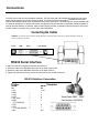
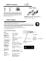
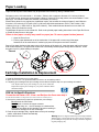
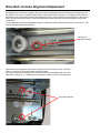
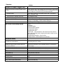
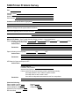
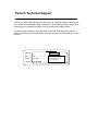
5351 Series Printer
Technical Support Documentation
Pertech Resources Inc. 2007
2202xxx
Rev.00
Disclaimer
Information in this document is subject to change without notice. Consult your Pertech® sales representative for information
that is applicable and current. Pertech reserves the right to improve products as new technology, components, software and
firmware become available.
No part of this document may be reproduced or transmitted in any form or by any means, electronic or mechanical, for any
purpose with out the express written permission of Pertech.
Copyright
Copyright © 2007 by Pertech Resources, Inc.
Riverton, Wyoming USA
All rights reserved
Printed in USA
Confidential, Unpublished
Property of Pertech Resources, Inc.
Trademarks
PERTECH® is a registered trademark of PERTECH RESOURCES, INC.
Other trademarks and registered trademarks are the property of their respective holders
Web site
http://www.pertechresources.com/
Federal Communications Commission (FCC) Radio
Frequency Interference Statement
Warning
Changes or modifications to this unit not expressly approved by the party responsible for compliance could void the user’s
authority to operate the equipment.
Note
This equipment has been tested and found to comply with the limits for a Class B digital device, pursuant to Part 15 of the
FCC rules. These limits are designed to provide reasonable protection against harmful interference when the equipment is
operated in a commercial environment. This equipment generates, uses, and can radiate radio frequency energy and , if
not installed and used in accordance with the instruction manual, may cause harmful interference to radio communications.
Operation of this equipment in a residential area is likely to cause harmful interference in which case the user will be
required to correct the interference at his own expense.
Information to the User
This equipment must be installed and used in strict accordance with the manufacturer’s instructions. However, there is no
guarantee that interference of radio communications will not occur in a particular commercial installation. If this equipment
does cause interference, which can be determined by turning the equipment off and on , the user is encouraged to contact
Pertech immediately.
Pertech is not responsible for any radio of television interference caused by unauthorized modification of this equipment, or
the substitution of attachment or connection cables and equipment other than those specified by Pertech. The correction of
interferences caused by such unauthorized modification, substitution or attachment will be the responsibility of the user.
Industry Canada
This Class B digital apparatus complies with Industry Canada Standard ICES-003.
Cet appareil numérique de la classe A est conforme à la norme NMB-003 d’Industrie Canada.
Important Information to the User
In order to ensure compliance with the Product Safety, FCC and CE marking requirements. you must use the power supply,
power cord, and interface cable which were shipped with this product or which meet the following parameters:
Power Supply
Input power to this product must be provided by one of the following:
(1) A NRTL Certified power source with a Limited Power Source
(LPS) output for use in North America, input rated 100 - 240 Vac, 1.5 A, 50/60 Hz, Output rated 24Vdc, 2.5 A Maximum and
60W Maximum. or
(2) A power source with a Limited Power Source (LPS) output Certified by an agency recognized in the country of
installation, input rated 100 - 240 Vac, 1.5 A, 50/60 Hz, Output rated 24Vdc, 2.5 A Maximum and 60W Maximum. Use of this
product with a power supply other than the Pertech power supply will require you to test this power supply and the Pertech
printer for FCC and CE mark certification.
Interface Cable
A shielded (360 degree) interface cable must be used with this product. The shield must be connected to the frame or earth
ground reference at each end of the cable.
Use of a cable other than the described here will require that you test this cable with the Pertech printer and your system
for FCC and CE mark certification.
Power cord
For North America a NRTL Recognized detachable power cord must be used. For applications where the power supply
module may be located on the floor, a power cord with Type SJT marking must be used.
For applications outside of North America, Power cords which meet the country of installation’s certification and application
requirements must be used.
Use of a power cord other than described here may result in a violation of safety certifications which are in force in the
country of use.
Pertech Resources Proprietary
Notice: This drawing and/or technical information is Proprietary to Pertech
Resources Inc. , and is issued in confidence, and may not be reproduced
or used to manufacture anything without written permission from Pertech
Resources Inc., and is loaned for mutual assistance to be returned when its
purpose is served.
Contents
Preface ...........................................................................................................................................5
Ordering Paper and Supplies .......................................................................................................6
LED Mode Indicators ....................................................................................................................7
Validation and Document Guides ................................................................................................9
Document Guide Installation......................................................................................................10
Document Drop Stop Installation............................................................................................... 11
Connections.................................................................................................................................14
Paper Loading..............................................................................................................................16
Drive Belt -Column Alignment Adjustment ...............................................................................17
Configuration ...............................................................................................................................18
Inspection & Testing ...................................................................................................................21
Visual Inspection ............................................................................................................21
1. Determine Model Number ............................................................................................21
2. Determine Revision ......................................................................................................21
3. Determine Printer Date.................................................................................................21
4. Determine Serial Number .............................................................................................21
5. Parts Identification .......................................................................................................22
6. Parts Inspection...........................................................................................................23
Operational Test Procedure...........................................................................................27
1. Power supply .............................................................................................................27
2. Paper out - Paper Load -Paper Feed Button..............................................................27
3. Lid Open Switch .........................................................................................................27
4. Validation ....................................................................................................................28
5. INK Low - Out .............................................................................................................28
Printer Resident Tests .....................................................................................................29
Printer Inspection and Testing Data Sheet ..................................................................30
Trouble Shooting .........................................................................................................................31
Trouble Shooting General Issues .....................................................................................32
Fault Mode Diagnostics .................................................................................................34
Mechanical Error .......................................................................................................34
RAM ERROR..............................................................................................................34
Program Error/ Firmware Error...................................................................................34
Home Sensor Error.....................................................................................................34
No Power Light ..........................................................................................................34
Paper Light On ...........................................................................................................34
Red Power Light On ....................................................................................................34
Green Power Light On.................................................................................................35
No Print & Print Quality Issues ....................................................................................35
Validation issues..........................................................................................................35
Other............................................................................................................................35
5300 Printer Problem Survey.........................................................................................36
Pertech Technical Support .........................................................................................................37
Preface
This manual has been written to help you Install and Operate your Pertech® 5300 Series Printer. Feel free to contact
us if you need further assistance after reading this manual. Please see the Troubleshooting Printer Problems section of
this manual and determine the complete part number of your printer prior to calling. Pertech provides technical support
Monday through Friday from 8:00 AM to 5:00 PM MST at 307-856-4821.
Every effort has been made to insure the information in this manual is complete and accurate. Feel free to contact us
with any comments concerning this manual. Pertech assumes no responsibility for errors.
Where to Get Additional information
The following publications contain more information about the 5300 series printer. Contact your Pertech sales representative to obtain additional copies of this Manual or any of the publications listed below.
Title
Part Number
5300 Printer: Setup Guide
5300 Printer: Users Guide
5300 Printer: Service Guide
5300 Printer: Programming Manual A470
5300 Printer: Programming Manual ACL
5300 Printer: Programming Manual D0214
5300 Printer: Programming Manual ZC 5999 / 5979
5300 Printer: Programming Manual ZC 2979
5300 Printer: Programming Manual ZC 1939 / 2059
220322
220321
220323
220282
220320
220284
220285
220286
220325
Available Models:
5351 Ink Jet Receipt / Independent Validation
5354 Ink Jet Validation Only
5371 Impact Receipt / Independent Validation
5374 Impact Validation Only
Ordering Paper and Supplies
The following section lists the paper and supplies available for order. In addition to paper and ribbons,
parts, service and repair may be obtained by calling 1-800-800-6614.
Paper:
Call: 1-800-800-6614
Paper
Part Number
Ink Jet 5351
One Ply....................................................................................................... 103292057
Impact 5371
One Ply....................................................................................................... 103292062
Two Ply ....................................................................................................... 103292061
Cartridge’s:
Call: 1-800-800-6614
Description
Part Number
Ink Jet 535X
Black........................................................................................................... 108541001
Impact 537X
Black........................................................................................................... 100629011
Purple ......................................................................................................... 100629012
Cables:
Call: 1-800-800-6614
Description
Part Number
5300 Printer RS232 Serial Cable 6’ ............................................................. 106356010
5300 Printer Certified USB Cable 6’ ............................................................. 106356011
5300 Printer Certified USB Cable 10”........................................................... 106356014
5300 Printer A470 Serial Interface adapter................................................... 106356013
Documentation:
Call: 1-800-800-6614 - or downloadable at www.pertechresources.com
Title
Part Number
5300 Printer: Setup Guide ............................................................................ 220322
5300 Printer: Users Guide .......................................................................... 220321
5300 Printer: : Service Manual ..................................................................... 220223
Parts Information Manual (PIM)..................................................................... 220324
LED Mode Indicators
The 5300 series printers are equipped with two color led indicators that identify Paper, Error,
Ink Low, Form In, and Power On conditions.
Status
Left LED
Right LED
Power On
Off
Green
Insert form
Blink Green
Current Status
Form is in
Green
Current Status
Error
Off
Red
Ink Low
Current Status
Blink Amber
Ink Cartridge Out
Current Status
Amber
Paper Out
Blink Red
Current Status
Cover Open
Current status
Blink Green
Power On
Insert form
Form is in
Error
Ink Low
Ink Cartridge Out
Paper Out
Cover Open
�����
�����
��� ���
�����
����
�����
�����
��� ���
�����
����
�����
�����
��� ���
�����
����
�����
�����
��� ���
�����
����
�����
�����
��� ���
�����
����
�����
�����
��� ���
�����
����
�����
�����
��� ���
�����
����
�����
�����
��� ���
����
�����
LED Error Fault Mode Diagnostics
The printer will enter a Fault Mode and will not operate when certain failure conditions are encountered. Confirmation
of this condition can be accomplished by the host on the DTR (pin 8) or status with an RS-232 interface.
A Printer in fault mode will not feed paper when the paper advance button on the top cover is depressed nor will it
execute commands other than immediate commands that are executed even when the printer is in a fault condition. Immediate commands are high-level commands that are typically executed prior to low-level commands that
are stored in the input buffer. They are received and processed regardless of the printer’s fault state or communications interface busy status.
ACL Control Language Immediate Commands
(See 5300 Programing Manuals for details on these and other Compatibility Mode available commands)
Immediate status transmission
DLE EOT
10 04
16 4
n
Immediate recovery from fault
DLE ENQ
10 05
16 5
n
Immediate peripheral pulse
DLE DC4
10 14
16 20
s m n
Immediate printer reset
DLE @
10 40
16 64
The color of the Power LED on the front panel of the printer will change from Green to Red if a fault condition is encountered. Depressing the paper feed button on the printer cover will cause the printer to enter diagnostic mode. This
will cause the LED to flash a 3 bit code to define the specific reason the printer entered Fault Mode. The error code is
followed by a delay before being repeated. The diagnostic code will toggle the DTR line and flash the Red LED if the
RS-232 interface is selected. It will toggle the fault line and flash the green led if parallel interface is selected.
�����
�����
��� ���
����
�����
Diagnosed failure
Error Code
Dot
Dot
Dash
Mechanical Error (most likely compensator, wiper problem)*
Dot
Dash
Dot
Ram Error***
Dot
Dash
Dash
Program Error / Firmware Error***
Dash
Dot
Dot
Home Sensor Error **
* Clamp functionality, wiper engage and disengage
** Failed sensor, control board problem, mechanical problem or dirty sensor. The later has
proved to be the most common and can be resolved by cleaning paper dust and other debris
from the sensors and code wheel.
***Failures diagnosed with error codes indicating a problem with the firmware or control board.
The printer will remain in FAULT Mode until the power is cycled or the printer is reset with a immediate reset command.
Validation and Document Guides
Validation Print Fields
The 5300 series printer has 2.5 inch wide print field.
The validation print field height is adjustable from .17 to 1.75
inches. This can be done via the configuration utility or the
one button setup. An inserted form can be manually aligned
or a optional document guide can be attached to provide a
fixed right side stop for the inserted form. The drawings below indicate the typical print positions for a 2 3/4” X 6” form.
The highlighted area is the print field width and Maximum
height.
Note: The one button set-up only has three selectable document
stop settings. Using the Configuration Utility the document stop
can be adjusted to any desired print field height within the parameters specified above. See Configuration and Diagnostics section of
this manual for available options.
Dot column #1 Dot Column #400
3 Inches
Print Zone
2 Inches for 6” Check
1 Inch
1.75 Document Stop
Print field is 2.5” Wide
Center Justify
3.25 Inches
3 Inches
Print Zone
2 Inches for 6” Check
1 Inch
1.75 Document Stop
Print field is 2.5” Wide
Left Justify
3 Inches
Bank of First Deposit (BOFD) Endorsement A470, bit [print field is ;larger @ 72
To 2” Print Zone:
Doc ument Guide
3 Inches
Left Justify
Right Justify
Print Zone
2 Inches for 6” Check
1.75 Document Stop
2.5” Wide Print Field
Print field is 2.5” Wide
Right Justify
3 Inches
Print Zone
2 Inches for 6” Check
1 Inch
3.5 Inches
3 Inches
Print Zone
2 Inches for 6” Check
1 Inch
1.75 Document Stop
Right Edge of Form Aligned with Right
Edge of Receipt Retail Endorsement. To
center justify check in print zone, document guide is 2.625” from dot column #1
Print field is 2.5” Wide
Right Justify
2.75 Inches
Right Edge of Form Aligned with Right
Edge of Receipt BOFD Endorsement
Effective print area in Endorsement zone
is 1.75” wide.
1.75 Document Stop
Print field is 2.5” Wide
Right Justify
1 Inch
2.75 Inches
Note: The Print Field is 2.5” wide. Left Justification
will overlap into the 1” right zone. Right Justification
will overlap into 3” left zone.
1 Inch
Document Guide Installation
The Document Guide is a clip in durable plastic part that attaches to the printers Validation Roller to provide a
right side guide for an inserted form.
NOTE: Before installing the Document Guide make sure the area where the guide is to be installed is free of any dust
debris or contamination that could inhibit the movement of the Validation Roller.
The Document Guide is installed by
attaching it to the Validation Roller. The
guide is installed vertically with the bottom of the guide clipped into the Validation Roller in the rollers notch on the
right side. The tapered tab end of the
guide needs to be toward the top of the
printer. Align the bottom two extensions
of the Document guide so that they are
left of the MLV Roller Gear. Make sure
an inserted form will not catch on the
guide.
Tab
MLV Gear
When the Document Guide is attached the
Print is Left Justified to the 2” Print Zone on the
back of a 2 3/4” X 6” standard check.
Note: The Print Field is 2.5” wide. Left Justification
can overlap into the 1” right zone.
3 Inches
Print Zone
2 Inches for 6” Check
The print field will be 1/4”
left of a standard 2 3/4”
X 6” form when inserted
vertically and aligning
with the document guide.
1 Inch
1.75 Document Stop
Print field is 2.5” Wide
3 Inches
1.75 Document Stop
Print field is 2.5” Wide
1 Inch
2.75 Inches
Document Drop Stop Installation
A pair of tweezers, mylar Document Drop Stop,
PN# 108693 (DDS), and an Alcohol Prep are the
Items necessary to do this installation.
Pre-Install:
1. Open front cover.
Print head should move to right side, compensator
validation clamp position should be open.
Front cover can be removed or left on.
(Front cover is removed in this document for
viewing purposes).
2. Turn power off and disconnect from power source.
3. Remove interface and cash drawer cables.
4. Remove ink cartridge.
Rear Cover Removal:
1 To remove the rear cover there are 4 locking appendages that hold the rear cover in place.
2 Applying inwards pressure and pushing the case
upwards on the front lower sides will release the two
front appendages from the lower case.
3 Once the front locking appendages are released
the rear locking appendages can be released by applying pressure inside the paper bucket on the back
edge of the case top.
4 Lift the rear cover off of the printer.
1
2
3
4
Document Drop Stop Placement
Bend in Mylar
DDS
1
2
Clean the installation area with an alcohol swab and peel the backing off the
(DDS).
With a pair of tweezers attach the DDS
to the paper deflector assembly. (See
PICTURES BELOW & PREVIOUS
PAGE FOR PROPER ALIGNMENT )
3
4
Reassemble & Test printer.
If installed into Impact 537X model, with
compensator closed, push print head left
to right to be sure print head shield clears
DDS. A clicking noise will be heard if
DDS is catching on the print head shield.
Remove and repeat installation if this
should occur.
Connections
The 5300 comes with two communication interfaces, RS-232 Serial and USB. Additionally, the printer has a cash
drawer port and a three pin mini din power coupling. The RS-232 interface connector is a DB9M connector and
requires a Null Modem Serial cable for standard PC to printer connections. The USB Interface uses a standard USB
2.0 cable for standard PC to printer connections. A single tele-jack port provides a cash drawer interface capable of
running two cash drawers. An external Class 2 Power Supply provides 15 watt Min output to the printer. All connectors are located on the back of the printer in the order listed below.
Connecting the Cables
Caution: Be sure the power switch is turned off before connecting cables. The host computer should be turned off
before connecting any cables.
Power
USB
Serial
Cash Drawer
RS232 Serial Interface
1. Make sure the host computer and printer are turned off.
2. Attach the cable to the DB9 Male connector on the back of the Printer.
3 Attach the cable to the DB9 Male connector on the back of the PC.
4. Tighten the connector screws to secure the cable and ensure a solid connection.
RS-232 Interface Connection
Printer
DB-9M
Pin
1 N/C
2.RXD
3 TXD
4 DTR
5 SIG. GND.
6 DSR
(TTL FORM IN)
7 RTS
8 CTS
(TTL LOW PAPER)
9. N/C
←
→
→
←
←
→
→
←
→
DB-9M
Pin
1 N/C
3
2
6
5
4
8
7
N/C
Computer
Serial Cable DB9F - DB9F
Part Number 106356010
USB 2.0 Interface
Pin 1
Pin 2
Pin 3
Pin 4
Pin 5
Pin 6
USB Cable Part
Number 106356011
EOT/VCC
DD+
GND
GND
GND
The USB cable may be attached or detached when the
system is on. When Using the USB interface the Windows® Operating System will automatically install the
USB port driver. Pertech has available printer drivers at
www.pertechresources.com.
Warning: When Hot Swapping USB cable make sure
that cable is installed into the correct connectors or
damage to the printer could result.
Power Supply
To avoid damage to the printer connect the Power Supply last.
1. Make sure the printer power switch is off.
2. Plug the Power Supply Cable into the printer. The power supply cable connector has a
locking mechanism to ensure that the cable stays fastened to the printer. When removing
the cable release the locking mechanism by pulling the mechanism away from the printer.
3. Plug the Power Supply Cable into a grounded outlet.
4. Turn the power switch on. The Power LED on the front of the
Printer will illuminate to green.
Ink Jet 535X Power Supply
INPUT
Input Voltage:
Input Current:
Input Frequency
OUTPUT
Output Voltage:
Output Current:
Rated Output Power:
Load Regulation:
Line Regulation:
Ripple Voltage:
Inrush Current:
Efficiency:
PROTECTION
Over-voltage:
Short Circuit:
APPROVALS
Safety Marks:
EMI:
PHYSICAL
AC Plug:
DC Cord Length:
DC Plug:
90Vac To 255Vac
<.5Arms At 90Vac
47Hz To 63Hz
24VDC
.625A Minimum, No Minimum
Load Required
15 Watts Minimum
+/- 5%
+/- 1%
250mV Peak To Peak
30A @ 115Vac, 40A @ 230Vac
60% Minimum, 75% Typical
25.6Vdc TO 30Vdc
Auto-Recover Upon Removal
Of Short
UL, CSA or CUL, *CE, *TUV
FCC Part 15 Class B
(Both Radiated And Conducted)
On Wall Mount Adapter
1830mm (6 FT.)
3-pin Locking Mini Din
(See Pinout Above)
Connector Cable Locking
Mechanism
�����
�����
��� ���
����
�����
Paper Loading
Paper and other printer consumables may be purchased from Pertech by calling 1-800-800-6614.
Roll paper must be 3.0 inches wide +/- .03 inches (.762mm) with a maximum diameter of 3.5 inches (88.9mm).
Ink Jet 535X receipt printers can accommodate 1 paper ply. Impact 537X receipt printers can accommodate 1 or two
paper plys. The minimum inside core diameter is 5/8 inches (15.875mm).
Inserted forms allow for one original plus 2 additional copies, this includes the receipt roll paper if used. Minimum
form size is 5.5 inches by 2.75 inches (139.7 by 69.9mm) with thickness between .0015 to .0047 inches (.0381.1194mm) for 2 ply s, .0026-.0047 for 1ply(.066-.1194mm) . Total media thickness allowed is no more than .012
inches (.305mm) includes the receipt.
To load paper the power must be turned ON. Refer to the pictorial paper loading instructions in the Paper Roll Cover
or Follow the instructions on this page.
Failure to load paper correctly may result in a paper jam. To remove paper that has jammed:
1. Open the Front Cover.
2. Pull the paper backwards out of the mechanism. If the paper will not remove pull the paper
forwards out of the mechanism. If needed cycle power to the printer and wait 5 seconds.
Drop roll into paper bucket so that paper comes off the bottom of the paper roll. Insert the paper end into the paper
feed actuator assembly. The paper feed actuator will automatically feed the paper through the mechanism . Close
the paper cover lid, paper loading is complete.
Correct
Incorrect
Cartridge Installation & Replacement
1. Press the Power Switch to turn on the printer.
2. Open the front cover. The printhead cradle will move to an accessible position.
3. If replacing print cartridge lift the print cartridge out and discard. Skip this step if no print cartridge is installed.
Note: Replacement ink jet print cartridge for your printer 108541001
Replacement impact print cartridge for your printer 100629011 Black
100629012 Purple.
535X Ink Jet Specific Directions
To reset the Ink Status LED - Close and Re-Open the Cover after Step 3
(See INK STATUS RESET in Configuration section of this manual for available options.)
4. Remove the protective vinyl tape from replacement print cartridge.
Do not touch the Ink nozzles.
Do not touch or remove the copper contacts.
Do not Tap, bang, etc.... the ink cartridge on a hard surface.
Doing this can cause the ink cartridge to de-prime resulting in
reduced ink cartridge life or loss of cartridge.
5. Push the print cartridge firmly, angled down into the print cartridge
cradle, cradle latch will latch automatically.
6. Close the front cover.
Warning: Printer is shipped without the print cartridge installed.
When shipping or transporting printer remove the ink cartridge to
prevent damage to the printer. Ink cartridges should be shipped in
original packaging only.
Drive Belt -Column Alignment Adjustment
Belt adjustment is usually not necessary, but if the column vertical alignment is off the drive belt assembly should
be checked. The screw (1.) Should be tight and the belt should not have any play in it. To adjust the belt, back the
adjustment screw off enough so that the drive assembly is free to move. Move the print head carrier to the left and
then to the right and back to center. Tighten the Adjustment Screw and check the column alignment via a printer
resident test.
Column alignment can also be adjusted by using a configuration utility that Pertech Provides on our web site. This
method does not adjust the belt tension.
Belt Tension
Adjustment Screw
Issues with column alignment can also be caused by loose Drive Motor screws. The drive
motor is not visible, it is mounted under the printer chassis.
If loose you may notice a clacking noise., check by moving the cartridge holder from left to
right with the power off . If a clacking noise is heard the screws may need to be tightened.
Drive Motor Screws
Configuration
Configuration Report & Setup Mode
After the printer is set up, you can run two print diagnostic reports / tests and
enter the configuration menu. Below is an example of the configuration report.
1 Press and hold the Paper Feed Button and then
press the Power Switch to turn the printer on and
start the first test.
Validation printers will perform a Self Test if a form is
detected, when the power is turned on.
Release the Paper Feed Button after 4 seconds for
the printing to begin.
The 5300 completes a test of RAM , a checksum
test of program memory, homing and maintenance
of the print head, and then prints the configuration
settings.
2 To change the configuration settings, press the
Paper Feed Button when prompted, the Left LED
will begin flashing.
Serial Number:
Main Firmware
Revision:
CRC:
Boot Firmware
Revision:
CRC:
Font:
PRESSING THE PAPER FEED BUTTON WHILE THE
GREEN LIGHT IS FLASHING WILL REJECT THE
LAST PRINTED PARAMETER. IF THE BUTTON IS
NOT PRESSED WITHIN 5 SECONDS. THE PARAMETER WILL BE ACCEPTED AND THE NEXT SET-UP
OPTION WILL BE LISTED.
PRESS THE PAPER FEED BUTTON NOW TO
REJECT THE CURRENT CONFIGURATION AND
CONTINUE WITH THE PRINTER SET-UP.
A. Entering the configuration mode, the printer prints
the Set-Up Instructions and prompts the user to
press the feed button to reject the current settings.
B. If you don’t want to change an option, wait for five
seconds and the next option will print.
C. After completing the Configuration Mode, the
printer prints the new configuration settings and
stores them in non-volatile memory.
Note: Exiting setup early by turning the printer off will
erase any changes made to the configuration. You must
complete the setup for changes to take effect.
Standard
Draft
USA
437 USA
6 Lines Per Inch
6 Lines Per Inch
Model Number
Hardware
Memory
=================================
SET-UP INSTRUCTIONS
Font:
Font Quality:
Intl Char set:
Code Page:
Receipt LPI:
Validation LPI:
USB (when used)
Descriptor:
Note: If Ink Status Reset is set to “Manual”, first option
to print will be “Press feed to Reset Ink Tally”.
Press paper feed to change configuration
ACL Language
Standard Print
CR = CR
Automatic
57.6K
8-bits
1-bit
None
Hardware
�����
Note: Validation-Only printers do not have this feature.
* ** ***
****
RS232 Serial (when used)
Baud Rate:
Data Bits:
Stop Bits:
Parity:
Flow Control:
��� ���
����
* ** ***
****
Printer Control Language
PCL:
Diag Mode:
Auto LF:
Soft Fault Recover:
�����
�����
********
Tallies
Validation Clamp:
Form Insert Wait:
Paper Low Sensor
Ink Status Reset:
Document Stop:
Column Alignment
Half Speed:
Full Speed:
Closed
1 Min
Enabled
Automatic
1.75 Inches
Installed RAM:
Installed ROM:
Total User Flash:
Flash Logos
Flash Fonts
Flash Macros:
Flash Raw Data:
Total User Ram:
Ram Logos:
Ram Fonts:
Ram Macros:
128K
512K
64K
32K
0K
0K
32K
24560
24560
0K
0K
Printed Lines:
Dot Count:
Validation Opens:
Feed Distance:
Hours On:
Flash Updates:
Cover Opens:
0
0
0
0
0
0
0
Diagnostic:
0
0
3
10
0
====================================
Press paper feed to change configuration
Press paper feed to enter print test
3 Otherwise, wait 10 seconds
and you can choose to enter
an Extended Print Test. After
this test, or Ignoring this
option, will return the printer
to normal operation after 10
seconds.
4. Extended Print Test: Checks
the printers vertical line
alignment, character fonts, and
pitches.
1
Configuration Example:
=================================
Configure the RS232 Serial parameters for the printer using the
configuration menu.
Press paper feed to change configuration
SET-UP INSTRUCTIONS
PRESSING THE PAPER FEED BUTTON WHILE THE
GREEN LIGHT IS FLASHING WILL REJECT THE
LAST PRINTED PARAMETER. IF THE BUTTON IS
NOT PRESSED WITHIN 5 SECONDS. THE PARAMETER WILL BE ACCEPTED AND THE NEXT SET-UP
OPTION WILL BE LISTED.
2
PRESS THE PAPER FEED BUTTON NOW TO
REJECT THE CURRENT CONFIGURATION AND
CONTINUE WITH THE PRINTER SET-UP.
3
ACL Language
Draft
USA
437 USA
6 PLI
:6LPI
RS232 Serial (when used)
Baud Rate:
57.6K
Data Bits:
8 Bits
Stop Bits:
1
Parity:
None
Flow Control:
Hardware
4
5
Baud Rate Options:
9600
19.2K
38.4K
57.6K
57.6
Baud Rate:
9600
Stop Bit Options:
1-Bit
2-Bit
Stop Bits:
6
1
2
Baud Rate:
3
1 Bit
Parity Options:
None
Even
Odd
Parity:
None
4
Flow Control Options:
Hardware
Software
Flow Control: Hardware
5
Flow Control: Software
USB (when used)
Descriptor:
7
Model Number
Hardware
Mechanism Model:JRNL / VAL
Validation Clamp: Closed
Paper Low Stop: Disabled
Ink Status Reset: Automatic
Document Stop: 1.75 inches
Column Alignment
Half Speed: X
Full Speed: X
Tallies
Printed Lines:
Dot Count:
Validation Opens:
Feed Distance:
Hours On;
Flash Updates:
Cover Opens:
Diagnostic:
0
0
0
Configuration Report to follow
Change to:
Baud Rate
57.6
9600
Data Bits
8
8
Stop Bits
1
1
Parity
None
None
Flow Control Hardware
Printer Control Language
PCL:
ACL Language
Diag:
Standard Print
Auto LF:
CR=CR
Font:
Font:
Font Quality:
Intl Char Set:
Code Page:
Receipt LPI:
Validation LPI
Current Parameters
6
7
Software
Press and hold the Paper Feed Button and then press the
Power Switch to turn the printer on.
Release the Paper Feed Button after 4 seconds for the configuration report to begin printing.
At the end of the configuration report the printer will prompt “
Press Paper Feed to Change Configuration” .
Press the Paper Feed Button.
The Setup instructions will print and prompt to:
“PRESS THE PAPER FEED BUTTON NOW TO REJECT
THE CURRENT CONFIGURATION AND CONTINUE WITH
THE PRINTER SET-UP”
Press the Paper Feed Button.
The First Menu Item will appear “Printer Control Language”.
Wait 5 seconds and the next Menu Item will appear “Font”. Wait
5 seconds and the “RS232 Serial (When Used)” Menu will appear.
Press the Paper Feed Button
The “Baud Rate Options” will appear
Press the Paper Feed Button
The currently selected Baud Rate “57.6K” will appear
Press the feed button until the 9600 parameter appears then wait 5
seconds for the next option.
The “Stop Bits” parameter will appear
Wait 5 seconds and the next Menu Item will appear “Parity
Options”. Wait 5 seconds and the next Menu Item will appear
“Flow Control Options”.
Press the Paper Feed Button
The currently selected Flow Control Option, “Hardware” will
appear
Press the Paper Feed Button until the “Software” parameter appears
then wait until the printer goes through the rest of the menus and
prints off the configuration Report.
Check the New Report with the old to make sure the setting are now
correct.
Printer Configuration Options
Serial Number:
Main Firmware
Revision:
CRC:
Boot Firmware
Revision:
CRC:
********
* ** ***
****
* ** ***
****
Printer Control Language
PCL:
Diag Mode:
Auto LF:
Soft Fault Recover:
Font:
Options for ACL Compatibility Mode
ACL Language
Standard Print
CR = CR
Automatic
Font:
Font Quality:
Intl Char set:
Code Page:
Receipt LPI:
Validation LPI:
Standard
Draft
USA
437 USA
6 Lines Per Inch
6 Lines Per Inch
���� ��������
���� � �������
���� � ��������
����� ���
����� ���
��������
��� �������������
���� ����� �
����������� �����
� ���
�����
USB (when used)
Descriptor:
Model Number
������ ������
Tallies
���� � ��������
����������
57.6K
8-bits
1-bit
None
Hardware
Memory
���� � ��������
��������
RS232 Serial (when used)
Baud Rate:
Data Bits:
Stop Bits:
Parity:
Flow Control:
Hardware
���� � ��������
��� ����
�� � ��
���� ����������
�������
������
����
��������
��
���
�����
����� �
������� �
������
�����
������
Validation Clamp:
Form Insert Wait:
Paper Low Sensor
Ink Status Reset:
Document Stop:
Column Alignment
Half Speed:
Full Speed:
Closed
1 Min
Enabled
Automatic
1.75 Inches
Installed RAM:
Installed ROM:
Total User Flash:
Flash Logos
Flash Fonts
Flash Macros:
Flash Raw Data:
Total User Ram:
Ram Logos:
Ram Fonts:
Ram Macros:
128K
512K
64K
32K
0K
0K
32K
24560
24560
0K
0K
Printed Lines:
Dot Count:
Validation Opens:
Feed Distance:
Hours On:
Flash Updates:
Cover Opens:
0
0
0
0
0
0
0
Diagnostic:
0
0
3
10
0
====================================
Press paper feed to change configuration
Press paper feed to enter print test
������� ��
���� �� �����
��������
������
��������� ������
Inspection & Testing
Test results should be recorded on a data sheet for each printer and should accompany the printer.
A sample data sheet is include at the end of this Section.
Visual Inspection:
The purpose of the visual inspection is to
determine if the printer is within its product life or
if the printer is missing parts, has broken parts
or needs to be updated.
1. Determine Model Numbers
2. Determine Printer Revision Number
3. Determine Printer Date
4. Determine Serial Number
5. Parts Identification
6. Parts Inspection (The parts listed below
should be visually inspected for wear,
breakage, broken seals contaminants
and debris. Additionally, any missing parts
should be noted).
a) Pressure Roller, Validation (seals)
b) Compensator assembly
c) Printhead Assembly
d) Case Parts
e) Paper Feed Button
f) Sensors
g) Paper Feed Assembly
h) Document stop
i) Power supply
j) Paper Mandrel
k) Interface Cable
Operational Testing:
The purpose of the operational test is to test the printer for in field
functionality.
1.
2.
3.
4.
5.
6.
Power supply
Paper out - Paper Load -Paper Feed Button
Lid Open Switch
Validation
INK Low - Out
Printer Resident Self Tests
a) Perform a Validation Self Test
b) Perform a Configuration Self-Test (Verify
Configuration).
c) Perform an Extended Print Test
d) Perform a Burnin Self-Test
Visual Inspection
The following information is located ion the bottom of the printer.
.
1. Determine Model Number
2. Determine Revision
3. Determine Printer Date
4. Determine Serial Number
Model Number
Revision
Date Code
Serial Number
5. Parts Identification
Item Number
Qty
#
Item Description
Item Number
Qty
#
Item Description
108628001A
1.00
101
MECH ASSY-I.J VAL. & RECEIPT
108635001A
1.00
141
CASE TOP REAR ASSY, BLACK
100261046
0.00
102
ADHESIVE (TORQUE SEAL, PURPLE)
108535010C
1.00
142
CASE-BOTTOM, BLACK
100173240
3.00
104
SCREW-WASHER
108536010A
1.00
143
CRADLE-BOTTOM, BLACK
100173386
1.00
105
SCREW-6-32 X .188 PH FLAT
108637001A
1.00
144
CRADLE TOP ASSY, BLACK
100173384
3.00
106
SCREW-SHOULDER
108636001A
1.00
145
CASE TOP FRONT ASSY, BLACK
100239002
1.00
109
SANDWICH MOUNT
108540002A
1.00
147
LABEL-LED, SUNLIGHT, BLACK
104315006A
4.00
120
FOOT
108548B
1.00
149
INSULATOR-PCB, 5300
107074008
1.00
123
POWER SUPPLY, 15W
108631A
1.00
150
GUIDE-RIGHT FORM EDGE
108469300B
1.00
125
ASSEMBLY- INKPACT PRINTER PCB
108693A
1.00
153
CATCH-FORM, MYLAR
6. Parts Inspection
a) Pressure Roller, Validation (seals) Make sure purple loctite seal is not broken.
b) Compensator assembly
Compensator
should have
pressure on the
validation roller.
Pushing lightly
on the indicated
area to test for
spring failure.
c) Printhead Assembly
Ink Cartridge Holder
Ribbon Head Connector
5
1
2
3
4
d) Case Parts
The case is a durable plastic that should be inspected for missing feet, cover latches that are broken or have
become disengage from their seats. The later is usually a indication that the printer has been dropped.
Addtiionally the paper roll cover should move freely and fit flush into the rear cover mold.
Case Latch Points
g) Paper Feed Assembly
Paper Feed Button
should engage the
activation switch on
the chassis.
h) Document stop
The Document stop is a virtual stop that is raised to the specific height that it is set for in the printers configuration.
To adjust the stop you can use the configuration setup procedures described earlier in this document.
i) Power supply
Make sure power supply pins are not bent and that the cable connector is locked onto the back of the printer.
The green power LED light on the front of the printer should be lit. If the Green light is on and you still have
questions on the power you can have the power supply tested by a certified electrician. Another way to test is
to attach power supply from another printer that is known to be working
f) Sensors
Lid Open Switch
With Lid Open switch inactivated (cover open) Led on front
of printer will Flash.
Form In Sensor
Keep free from dust and debris.
If form in sensor is not working a inserted
form will not be recognized. Fault mode
error will occur.
Paper Out Sensor
Located in the paper path below visibility.
Use Operational Test to verify working.
Carriage Home Sensor
Keep free from dust and debris.
If carriage stalls and error light occurs the
sensor may need to be replaced. Sensor
mounted on PCB.
j)
Paper Mandrel
Make sure the paper mandrel spins freely with no paper installed. Make
sure the mandrel in seated on both sides in the mounting slots.
Paper Mandrel Seats
k) Interface Cable
Check the cable to make sure no Pins are bent or the cord is not cracked or damaged.
Operational Test Procedure
1. Power supply
Check the power supply connectors and cable for any damage. Connect the power supply to the printer and
then to a power source. Turn the printer on . The green Power LED on the printer should light.
�����
LED
– is Green
Power supply
�����
��� ���
�����
����
Connector Cable Locking
Mechanism
2. Paper out - Paper Load -Paper Feed Button
a. Apply power to the printer turn the printer on switch to the on position, the print head should cycle, the paper
Paper LED indicator should light Red and be blinking the power LED indicator should light green. (Caution:
when connecting the power to the printer the correct sequence is to connect the printer to the power supply and
then connect the power supply to the power source).
b. Load a paper into the printer, paper should feed freely and straight.
Feed Button
c. Press the paper feed button to verify functionality.
Once paper is loaded Paper LED indicator should be off.
Printer Paper Out LED – is ON
Load a Roll of Paper
Printer Paper Out LED – is OFF
��� ���
��� ���
����
�����
����
�����
�����
�����
�����
�����
3. Lid Open Switch
With the Lid Open Switch depressed apply power to the printer, the print head should cycle and line up on left
margin, release the Lid Open Switch and the head should center. Release the switch and the Green Power LED
should blink. Indicates Lid open switch is working
Lid Closed LED – is Solid Green
�����
�����
Lid Open LED is Blinking Green
����
�����
�����
��� ���
��� ���
�����
����
�����
4. Validation
Validation can be tested by using the your application or by using the configuration test described in the Printer
Resident Tests section. Additionally, a 5300 Pertech demo program can be supplied for testing purposes.
When the application uses the correct control codes to initiate validation the printer will open the compensator for a
validation form to be inserted.
The Form LED will blink Green until a form is inserted. The Form LED will stop blinking when the Form In Sensor
detects a form. When the form is detected the compensator will close and the document will begin printing and
feeding out the top of the slot. Dust and Debris are the most common kind of sensor error. If the form in sensor gets a
piece of paper in it will flag the sensor and create a form detect situation. In many cases this will cause the application
to fail due to conflicting information between the printer and the host. It is best to keep the sensors clean and free of
debris. A regular maintenance with canned air at Ink Cartridge is recommended.
Waiting for Form Insertion
�����
�����
Form Detected
��� ���
�����
����
�����
�����
��� ���
�����
����
5. INK Low - Out
It is helpful to under stand just how the printer determines the Ink low and out conditions that are displayed by the
LED’s on the front of the printer.
The ink cartridge does not have the capability to tell the printer when it is running low, The printers firmware counts
the number of dots fired from the cartridge nozzles and records that information in Tallies ( See configuration test
in Resident Print Test in next section). The Dot Count Tally is used to determine when the printer has reached
approximately 93% of the installed cartridges life. When this occurs the Ink Low Led will turn on and begin blinking,
it will not turn off unless it is reset. To reset the ink the lid must be opened and the old cartridge removed. If the
configuration for the Ink Status Reset is set to Automatic (default), the cover is closed and then opened an additional
time before the new ink cartridge is installed. This will clear the blinking Ink Low LED.
The solid Amber Ink Low LED indicates that the cartridge has reached its Max dot count and should be out.
�����
�����
����
�����
�����
��� ���
��� ���
�����
����
�����
Note: The printer will not stop printing at a Ink Low condition, it will continue as if it had ink in the cartridge.
Printer Resident Tests
There are four routines resident in the printer. Each is initiated during power up with other specific action taken.
Confirm normal initialization prior to executing a self test by turning power on with the lid closed. Listen for the
mechanism to initialize, then rase the cover and ensure the printhead centers.
Validation Self Test
The validation self test in initiated by inserting a form in the validation slot and holding the paper feed button down for
approximately 4 seconds on power up.
If the printer will not accept a form, raise the cover and the compensator will open. Insert the form and begin the in it a
ion procedure above.
This test is useful to determine the default configuration for the printer and prints the firmware revision and settings.
It also confirms functionality of the form in sensor. The Document Stop must be adjusted to its downward position or
all of the configuration information may not be printed on the ticket. Adjustment of the Document stop should only be
changed when the form size changes,
If a Configuration Self Test is needed it is best to use the Journal mode test.
Configuration Self Test
The configuration self test is initiated by holding the paper feed button down for approximately 4 seconds on power
up.
This test is useful to determine the default configuration of the printer and prints the revision and mark numbers of the
firmware and printers settings. Additionally Tally are printed on the bottom of this test for number of printed lines, Dot
Count, Cover Opens. This information can help in diagnosing issues related to use.
Extended Self Test
The extended self test is initiated by holding the paper feed button down for approximately 4 seconds on power up.
After the Configuration Self Test prints the user is prompted to “Press paper feed to change configuration”, letting this
option pass the printer will then prompt to “Press paper feed to enter print test”. Pressing the feed butt will result in a
rolling ASCII pattern printing.
This test prints the printable characters in the character set and is useful to verify print quality across the entire print
field.
Burn-In Self Test
The burn-in self test in initiated by turning the power switch on while the paper feed button is depressed and the front
cover is open. When the paper feed button is release and the front cover is closed the Burn-in Self Test will begin.
Once the rolling ASCII printing pattern begins it will continue for 48 cycle. At the end of each cycle the validation clamp
will open and close several times.
This test prints rolling ASCII characters followed by repeated clamp actuation and form feed roller activity. The printer
will be inactive for about 18 minutes before starting over with the next extended self test. This sequence will continue
until the power is interrupted, a paper out condition is encountered or 48 blocks have been printed. The complete test
will consume a full roll of single ply and about 16 hours of time.
This test is useful to ensure the printer functionality and validation clamp actuation. It also provides an opportunity for
intermittent failures recur and can screen for infant mortality when new electronic components have been installed.
Printer Inspection and Testing Data Sheet
Testing Individual
Test Date
Test Location
Accepted
Failed
Notes
Model Number
Revision Number
Serial Number
Environmental Conditions
Visual Inspection
Pressure Roller, validation
Compensator assembly
Printhead Assembly
Ribbon Feed Assembly
Case Parts
Paper Feed Button
Sensors
Paper Feed Assembly
Document Stop
Power supply
Paper Mandrel
Interface Cable
Operational Testing
Power supply
Paper Out - Load - Feed
Lid Open Switch
Validation
Ink - Low - Out
Validation Self Test
Configuration Self-Test
Extended Print Test
Burnin Self-Test
Printout Results
Application Interface Test
Seals
Trouble Shooting
Trouble shooting information should be recorded on the accompanying 5300 Printer Problem Survey located on at the end of this section. Trouble Shooting procedure should begin with the identification of the
customer, printer and customer issue. Follow the chart below for trouble shooting information.
Many printer issues can be easily solved without having to have the printer serviced by a technician. Below is a table
of Issues that will help identify and resolve many of these issues. Additionally, If you have more than one printer and
one printer is performing correctly:
Swap printers to see if the system or printer has the Problem.
Swap cable to see if the cable is the problem.
Compare the configurations between the two printers.
NOTE:
Actions listed are possible solutions to a symptom and do not reflect all possibilities for a specific symptoms solution.
Customer Information
Printer Information
Issue Identification
Symptom
Amber Light On
NO Power Light
Red Power Light
Red Paper Light
Green Power Light
Action
Operational Test Procedure
Visual Inspection
Visual Inspection
Paper LED
Trouble Shooting
Sensors
Visual Inspection
No Print and Print Quality Issues
Validation Issues
Other Issues
Cartridge Loading
Operation Test Procedure Ink -Low Out
Mechanical Error
Trouble Shooting
Paper Jam
Visual Inspection
Operational Testing
Sensors
Compensator Assy
Drive Motor Assy
LED Error &Fault Mode Diagnostics
Ram Error
Program / Firmware
Fault Mode Diagnostics
Fault Mode Diagnostics
Other Issues
Visual Inspection
Form In Sensor
Document Stop
Compensator Assy
Drive Motor Assy
Belt Adjustment
Document Drop Stop
Paper Jam
Driver
Configuration
Trouble Shooting
Head Connector
Cartridge Holder
Home Sensor Error
Click on underlined text to Hyper Link
to document section.
Driver Motor Assy
Home Sensor
Trouble Shooting General Issues
A. Printer prints garbage when using RS-232 and/or printer occasionally prints garbage
even when not sending print job.
- Solution : Verify that the COM port is set up to match the attached printer. .
B. Printer is not printing and receive error message from Windows that it failed to print.
- Verify that the printer is connected and powered on.
- Cancel the document.
- Solution for USB users:
Windows may have assigned the 53xx printer to some other port than the one chosen during the install. Select a different “USB00x Virtual Printer Port”. To do this, go to 53xx Printer Properties and select the Ports tab. If the printer is on
and connected, but the 53xx icon displayed in the Printers and Faxes dialog box is grayed out, right click on the 53xx
icon and check “Use Printer Off Line”. Try sending the print job again. You may have to repeat this process if several
“USB00x Virtual Printer Ports” are displayed under the Ports tab until you find the correct port. Always remember to
cancel the documents that fail to print.
- Solution for RS-232 users:
Verify that the NULL MODEM cable is connected to the port selected by the printer driver. Verify that the baud rate, parity, data and stop bits match. If the printer is on and connected, but the 53xx icon displayed in the Printers and Faxes
dialog box is grayed out, right click on the 53xx icon and check “Use Printer Off Line”. Try sending the print job again.
Always remember to cancel the documents that fail to print.
C. When using a RS232 port and clicking on “Update Printer” or “Print”, Windows 2000 or
XP displays a message that says the port is not available, but no other applications are running.
Verify that a printer driver is not using the same COM port. Open “control panel, printers” or “printers and faxes” in
Windows and select the properties (right click on the printer icon) for each installed printer. Select the “ports” tab. If the
current checked port for any installed printer matches the COM port that is being used with the configuration utility, you
will need to select another port for the printer driver. This only needs to be done while the configuration utility is being
used. After the printer is configured, set the printer driver port back to the correct COM port
D. Utility does not communicate with USB connected printer.
If using Windows 98 SR2, you may need to contact Pertech Resources for Microsoft’s USBPRINT.SYS driver. Windows ME, 2000 and XP already include this driver.
If you have a Printer Driver for Windows 2000/XP installed using a virtual USB printer port, you may have to temporarily
re-assign the Printer Driver to a “File” port before using the configuration utility. Go to “Printers and Faxes”, right click
on the printer, select “Properties”, select the “Ports” tab, make a note of which USB port is checked, then check the
“File” port. After using the configuration utility, remember to switch the port back to the USB port that it was assigned to.
E. The power switch is turned ON but the printer is dead. The Green Status light is Off.
Make sure the outlet has power and the power cord is plugged into the back of the printer.
F. The printer will print a Configuration Report but will not respond to the system commands.
Check to see that the interface cable is connected to the back of the terminal/ PC, and to the back of the printer.
G. Amber Ink Low LED is flashing (See INK Cartridge installation).
Solution: Open cover remove Ink cartridge close front cover, open front cover, replace ink cartridge close front cover.
H. Paper Jam
Solution: Open cover and remove supply roll. Grasp paper and gently pull paper out of the printer if paper does not move freely
gently pull the paper the opposite direction momentarily until it frees. Once paper is removed be sure no paper bits still exist in the
printer. Depress paper feed button to verify all gear and rollers turn freely.
I. Problem: Cant load paper, Roller does not turn
Clean Paper dust away from paper out sensor lens, located at the back of the compensator assembly. If clean verity paper
is able to get to the sensor and be seen.
J. Problem: Column alignment is off.
Solution : Loosen screw on belt tension plate and allow extension spring to tighten belt fully before re-tightening the screw.
Loosen carriage motor drive motor screws and bias motor for full gear engagement. Clean rear stringer and apply a small
amount of NYE grease to stringer, cycle cartridge black and forth across the stringer to distribute grease.
K. Problem: Forms Skew
Solution: Verify the form path is free of obstructions. If skew still exists adjust MLV/Validation pressure rollers for even
pressure on each side of roller . If roller pressure is adjusted you mist re-adjust ink cartridge gap to print bar and then
wiper gap.
L. Problem: Light Print / Drop Outs
Solution: Replace ink cartridge. If still not printing well verify cartridge fits in holder correctly and connects to flex circuit. If
still not working problem maybe PCB - Change PCB
M. Problem: Printer Cycles print cartridge and then goes into fault mode (red light comes on in
right LED position).
Solution: Run diagnostic code (flashing LED) by holding paper feed button down while printer is in fault condition. Refer to
diagnostics code to help identify potential problem.
N. Problem: After turning printer of with front cover closed, the cartridge does not cycle and
both LED’s toggle on and off.
Solution: Open and close front cover. If head does not cycle check to be sure lid open sensor plunger is operation correctly. If plunger is correct replace PCB.
O. Problem: Can’t communicate with printer.
Solution : Verify interface cable is connected properly to host and printer , be sure PCL mode and printer settings are set
to match system.
P. Problem: Form Will not Feed
Solution: Place form in printer verifying the form is in the form edge sensor on chassis. Left LED light should turn green
when form is present. If not, clean any dust / etc. from sensor. If light still does not turn green replace PCB.
Symptom
No Power Light
& printer will not function
Paper Light On
Red Power Light On
Action
Check the power supply to make sure it is plugged in and the
printers power switch is turned on.
Check the connector on the back of the printer and the cord
connection to the power brick. If connected to a UPS, check the
UPS to make sure it is powered and working.
If the above actions do not correct the problem the printer should
be checked out by a trained technician.
Feed paper if light does not go out than printer should be
checked by a trained technician
• Power light is Red (not Green) and printer will Power off the printer, Remove the paper roll. Using Low Pressure
not respond.
Canned Air spray out the areas around the sensors.
Inspect for debris, worn part breakage, or obstruction:
• Compensator Assembly
• Print Head Carrier, Ink Cartridge
• Sensors
If the Status Light remains red after the above procedure see
“Fault Mode Diagnostics” section.
A Steady red light and jerky head
Symptom
Fault Mode Diagnostics
Check the print head carriage and drive belt.
Press the paper feed button for Fault Mode Diagnostics. If this
action produces no results printer may have a control board
failure or DC motor failure.
Action
The printer will remain in fault mode until the power is cycled.
Mechanical Error
Check for paper jam, Carriage is stuck, Wiper engage - disengage. Clamp Functionality
RAM ERROR
Program Error/ Firmware Error
Home Sensor Error
Problem with PCB or Firmware
Problem with PCB or Firmware
Dirty Sensor, Failed sensor, Control Board problem,
Symptom
Green Power Light On
Paper wont feed when pressing paper actuator Arm.
Action
Lower actuator arm is not engaging the feed switch or feed switch
is not working. Check arm by switch to see if it is obstructed, If not
printer needs to be checked out by a trained technician.
Double printing
Weak Stepper Motor or bad Stepper Motor Gear, Tight rewind
spring, Firmware, PCB
Vertical lines on validation test ticket
Dirty Validation Roller
Wobble messy wavy crooked characters
Column Alignment, Carriage Drive assy adjustment.
Illegible / Garbled Print
Check the application settings, printer configuration and the port
settings for compatibility ( Communication Settings)
line cut off
Ink cartridge Nozzle Plugged (replace Cartridge)
No Print & Print Quality Issues
Check:
• Cartridge
• Interface Cables
• Communication Settings
• Compensator Spring • Compensator drive
• Print Head - cable attached to main board connector head secure in the print head carrier. Inspect print head for debris or print
head obstruction.
• Compensator Assembly - loose, broken
•Lid Open Switch - Will the printer do a self test?
Validation issues
Printer prints when the Power is turned On, even Spray air in the validation slot and make sure no paper pieces or debris
though a form is not inserted.
are blocking the from in sensor.
Validation Clamp closes but ticket wont advance out of Val slot
Adjust Document Stop, Check Validation Roller to compensator
rollers for gap.
Validation Clamp wont open
Check Compensator Spring
Light print on one side
Check Validation Roller, Compensator Spring.
Other
Paper Backs up
Wrong firmware, bad PCB
Clunking sound
DC motor loose on Inner frame
Runaway head
PCB
Short jerks for head cycle
PCB
Noisy clatter on print head Carrier
Check Drive Belt Assy
5300 Printer Problem Survey
Date:
Company Name
Contact
Model Number
Serial number
Customer Indicated Problem. (Symptom)
What has changed with the system before the failure.
What was happening before the issue occurred.
What has been done to resolve the issue.
What is LED Status: (See Trouble Shooting Section for help in Issue identification)
Power Indicator on front of printer is:
RED
GREEN
If red determine error code
LED Error Code
Action Taken
OFF
Resolution
Paper Indicator on front of printer
Action Taken
ON
OFF
Resolution
LED Status is Green and Paper is OFF :
Action Taken
Resolution
Perform Self test:
Firmware / Rev. Number
Attached Configuration
If have more than one printer and one printer is performing correctly:
Can swap printers to see if cable or system is issue
Can swap cable to see if cable is issue
Can check the dip switches between the two for a comparison.
Check the following:
Paper Loaded Correctly
Power Supply working
Visual Inspection completed
Operational Test completed
Document Stop
Sensors
Paper Jam
Configuration
Amber
Pertech Technical Support
Pertech™ provides Technical Support for this product by calling 307-856-4821 between the
hours of 8AM to 5PM Monday through Friday MST, or by submitting a Support Inquiry at the
Pertech web site. www.pertechresources.com under the service/support section.
The Model Number, Revision, Date, and Serial Number can be located on the Label attached on the bottom of the printer. Please have this information available when you contact
Pertech™.
���� �� ��� ���
�����
5351
�����
���
��
����
�����
������
�� �� ����
535100001B
�����������
Made in the USA. by
Pertech Resources
Inc.
Pertech
Patents Pending