1
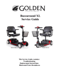
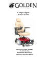
Compass Sport Service Guide This Service Guide contains: Troubleshooting Replacement Instructions Illustrated Parts Breakdown Compass Sport_SG_REVA_041211 1 Compass Sport_SG_REVA_041211 Table of Contents Nomenclature and Contact Information...................................................................................................3 ABOUT THE COMPASS SPORT SERVICE GUIDE............................................................................4 Compass Sport Components...................................................................................................................4-6 The SHARK Battery Gauge......................................................................................................................7 SCENARIO 1: Press the on/off button and the LED array does not light up (SHARK).......................8-9 SCENARIO 2: Batteries will not charge. (Shark Charging Test).........................................................9-10 Electrical System....................................................................................................................................11 Connector Key and Cabling for (SHARK).............................................................................................12 Wiring Diagrams and Battery Placement............................................................................................13-14 TROUBLESHOOTING GUIDE for (SHARK)..................................................................................15-21 Step 1: Checking Battery Voltage..........................................................................................................15 Step 2: Checking “Flash Codes”..........................................................................................................16-20 Flash Code #1 - User Fault.....................................................................................................................17 Flash Code #2 - Battery Fault.................................................................................................................17 Flash Code #3 - Left Motor Fault...........................................................................................................17 Flash Code #4 - Right Motor Fault.........................................................................................................18 Flash Code #5 - Left Park Brake Fault...................................................................................................18 Flash Code #6 - Right Park Brake Fault.................................................................................................19 Flash Code #7 - SHARK Control Unit Fault..........................................................................................19 Flash Code #8 - SHARK Power Module Fault.......................................................................................19 Flash Code #9 - SHARK Communications Fault...................................................................................19 Flash Code #10 - Unknown Fault...........................................................................................................20 Flash Code #11 - Incompatible Control Unit..........................................................................................20 Step 3: Check for other conditions displayed by the Shark Control Unit............................................20-21 All LEDs off...........................................................................................................................................20 All LEDs on steady.................................................................................................................................20 Left red LED flashing.............................................................................................................................20 Right to left LED chase...........................................................................................................................20 Left to right LED chase...........................................................................................................................21 All speedometer LEDs flashing..............................................................................................................21 REPLACEMENT INSTRUCTIONS...................................................................................................22-24 Drive Wheel............................................................................................................................................22 Front Caster.............................................................................................................................................22 Drive Train (Motor/Brake and gearbox).................................................................................................23 Power Module.........................................................................................................................................24 APPENDIX A - HOW TO USE A VOLTMETER..…………………………………………………..25 APPENDIX B - HOW TO USE AN OHM METER..…………………………………………………26 ILLUSTRATED PARTS BREAKDOWN..........................................................................................27-50 2 Compass Sport_SG_REVA_041211 Compass Sport Nomenclature 1. Seat Assembly 2. Control Unit (Shark) 3. Right Caster Cover 4. Left Caster Cover 5. Right Fender 6. Left Fender 7. Front Battery Cover 8. Rear Battery Cover 9. Base 10. Right Side Drive Train 11. Front Battery 12. Footplate 13. Power Harness with Circuit Breaker 14. Left Side Drive Train 15. Power Module (Shark) 16. Bus Cable 17. Rear Battery 18. Control Unit (Joystick) 2 1 5 6 3 4 8 7 9 18 17 16 10 13 Contact Information Golden Technologies 401 Bridge Street Old Forge, Pa. 18518 15 Toll-free: 800-624-6374 Fax: 800-628-5165 Lift Chair/Bed Tech: x645 Mobility Tech: x648 VA Tech: x647 Email: [email protected] 11 14 12 3 Compass Sport_SG_REVA_041211 About the Compass Sport Service Guide This service guide provides you with the information necessary to troubleshoot the Golden Technologies Compass Sport equipped with the Dynamic Shark controller. The troubleshooting scenarios in this manual consist of procedures that enable you to systematically trace and correct faults in the system. Before troubleshooting, check the following: • Make sure that the circuit breaker is reset. • Visually check terminals for corrosion. Check wires for missing insulation. • Make sure that the batteries are fully charged and in good working order. When possible, keep sets of known good batteries of various ratings in your shop at all times. The Compass Sport uses 35AH (U1) batteries. Problems that surface during troubleshooting are often due to the fact that the batteries are not fully charged or can not hold their charge. • Make sure that the electrical connections are secure. Unplug the connectors and make sure all of the pins are seated properly. Push the pins back into the connector housing if necessary. Make sure that the battery terminals are tight. NOTE: If you get to a point during troubleshooting where you cannot continue, call tech support at 800-624-6374. COMPASS SPORT COMPONENTS The Compass Sport is a battery-operated power chair controlled by a Dynamic control system. The control system monitors and displays flash codes on the LED array when it detects a fault in the system. The Compass Sport was designed to operate with between 18 – 24 volts (V) of direct current (DC). The Compass Sport control system is made up of the following components. Reference the diagrams on pages 11 and 12. • • • • • • • • • • 12V/(35AH) Batteries (2) Battery Harnesses (2) Main Circuit Breaker Battery Charger Power Harness Motors (2) (left/right) Park Brakes (2) (left/right) SHARK Dynamic Power Module SHARK Dynamic Control Unit (Joystick) SHARK Bus Cable NOTE: Parts and service must be authorized by the Golden Technologies Service Department. Unauthorized parts or service may void the warranty. For more information, contact the Golden Technologies Service Department at 800-624-6374 or [email protected]. Component: 12VDC (35AH) Batteries (2) Location: Connected in series inside the battery box. Function: Supply 24VDC to the power module. (12VDC x 2). Connections: Front Battery and Rear Battery. Failure Signs: Batteries drain quickly. Power chair runs slowly or not at all. Batteries will not charge, but charger is working properly. Flash Code #2. 4 Compass Sport_SG_REVA_041211 Tests: Load test. Fully charge the batteries first. Make sure charging system is working. Expected Readings: 12 - 14VDC each when fully charged. Serviceable: Replace batteries as necessary. Component: Park Brake (2) Location: End of each motor. Function: Park Brake for the motor. Connections: Each park brake has a 2 pin male connector, which connects to each motor harness. Failure Signs: Power chair will not move or moves sluggishly. No audible click when the chair stops. Tests: Test for open. See Flash Codes #5 and #6. Expected readings: Less than 80 ohms, but not shorted. Serviceable: Replace if outside this range. Component: Circuit Breaker Location: Mounted on the front of the power base. Function: Protects battery circuit from current overload. When the current draw exceeds the breaker rating, the circuit breaker will open. Connections: Terminals on the circuit breaker are connected to the batteries through the power harness. Failure Signs: Opens repeatedly. This may indicate a failed circuit breaker or short in the wiring. Also, may open if the motors are overloaded (from excessive weight, short in system, etc.) Test: Measure the resistance across the circuit breaker. Also check for continuity across the power harness from the circuit breaker to each battery. Refer to the power harness wiring diagram on page 13. Expected reading: Less than 10 ohms. Serviceable: Circuit breaker must be replaced with exact current rating. Replace power harness if no continuity. Component: Battery Charger Location: Stored inside a pouch on the seatback. Function: Recharges batteries. Connections: XLR connector connects to the charger port on the front of the control module. Failure Signs: Charger power LED does not go on. Batteries will not charge. Tests: Charger tests vary. Some chargers may be tested by measuring positive and negative leads on the charger connector. Other chargers need to see battery voltage before charging. Expected reading: Varies with charger. Serviceable: Replace if necessary. Component: Motors (2) Location: Left and right sides of the power base. Function: Drives the power chair. Connections: The right motor harness connects to M1 on the power module and the left motor harness connects to M2 on the power module. Failure Signs: Power chair runs slowly or not at all. Tests: Test for internal resistance in motor. Test motor wires for continuity. See Flash Codes #3 and #4. Expected readings: Internal resistance is less than 5 ohms but not shorted. Note: Can be as low as 0.3 ohms. Serviceable: Replace motor if outside range. 5 Compass Sport_SG_REVA_041211 Component: SHARK Power Module Location: Rear of the power base. Function: Monitors the system and displays faults when something in the system is out of range. These faults are displayed as a series of flashes by the battery meter. Connections: Control unit (joystick), DCI (not used), M1 (right motor), 24V (power harness from batteries), M2 (left motor). Refer to figures 1 and 2 on pages 11 and 12. Failure Signs: Flash Code #8. Tests: Measure voltage at SHARK Bus Connector pin 1 (battery positive) and pin 4 (battery negative). Expected readings: Battery voltage. Serviceable: Replace as necessary. Component: SHARK Control Unit (Joystick) Location: End of the armrest. Function: Provides user interface to the power chair. Also, shows battery charge and status of control system. Connections: XLR charger/programming port on the front of the control module. Bus cable connection on the back of the control module. Failure Signs: Flash Code #7 Tests: Measure voltage at pin 1 (battery positive) and pin 2 (battery negative). Expected readings: Battery voltage. Serviceable: Replace as necessary. Component: SHARK Bus Cable Location: Rear of SHARK Control Unit (Joystick). Function: Provides connectivity to the SHARK power module. Connections: 4 pin quick connect bus cable. Failure Signs: Flash Code #9 Tests: Measure continuity. Expected readings: Less than 10 ohms. Serviceable: Replace if open. 6 Compass Sport_SG_REVA_041211 The SHARK Battery Gauge The Battery Gauge is used to indicate power on and provides an estimate of the remaining battery capacity. Any green LEDs lit indicate well charged batteries. If only amber and red LEDs are lit, the batteries are moderately charged. Recharge before undertaking a long trip. If only red LEDs are lit, the batteries are running out of charge. Recharge as soon as possible. The following table indicates what the gauge will display for any given state. 7 Compass Sport_SG_REVA_041211 SCENARIO 1: Press the on/off button and the LED array does not light up. Before attempting to troubleshoot the power chair, make sure all connectors are connected and seated properly. Make sure that the batteries are connected properly and fully-charged. Refer to the wiring diagrams on pages 13 and 14 for the correct wiring. If the batteries are not fully charged or connected properly, then voltage measurements may produce faulty readings. Measure the voltage across the rear battery negative (black) terminal and the front battery positive (red) terminal to get battery voltage. If the batteries will not charge, go to “Scenario 2: Batteries will not charge.” 1. Check the circuit breaker. • If it is tripped – Reset it. • Not tripped – Go to the next step. • Tripped but does not reset – Remove the seat and front battery box cover. Go to step 12. 2. Measure voltage across pin 1 (B+) and pin 2 (B-) on the control unit (Joystick) charging socket. • 0VDC – Go to the next step. • 25VDC or (battery voltage) – Replace the control unit. Prevent damage to the Joystick. Be careful when inserting the meter leads into the charging socket. Do not allow the meter leads to touch each other, which will cause a short. 3. Disconnect the bus cable from the control unit (Joystick). 4. Measure voltage across pin 1 (+) and pin 4 (-) on the bus cable. • 0VDC – Go to the next step. • 25VDC or (battery voltage) – Replace the control unit (Joystick). 5. Remove the seat. 6. Remove the rear battery box cover. 7. Disconnect the bus cable from the power module. 8. Measure voltage across pin 1 (+) and pin 4 (-) on the power module. • 0VDC – Go to the next step. • 25VDC or (battery voltage) – Replace bus cable. 2 1 4 3 1 2 3 4 Prevent damage to the (Shark) power module. Be careful when touching the leads on the power module. Do not allow the meter leads to touch each other, which will cause a short. 9. Disconnect the power harness from the power module. 10. Measure voltage across the pin 1 (+) and pin 2 (-) on the power harness. • 0VDC – Go to the next step. • 25VDC or (battery voltage) – Replace the power module. 1 2 Before attempting to measure resistance, make sure there is no power to the circuit. Unplug the front and rear battery harnesses from the power harness 11. Measure Resistance across the terminals on the circuit breaker. • Less than 10 ohms – Go to the next step. • Open – Replace the circuit breaker. 8 Compass Sport_SG_REVA_041211 SCENARIO 1 - Continued 12. Check continuity across the circuit breaker wires of the power harness and across the battery wires of the power harness. Repair or replace the power harness as necessary. 13. Check continuity across both the front and the rear battery harnesses. If open, check in-line fuse and replace fuse or harness as necessary. Fuses must be replaced with exact type and rating. Note: When checking continuity, visually inspect wires, connectors, and pins for any damage and to make sure the pins are seated properly in their connectors. SCENARIO 2: Batteries Will Not Charge (Shark Charging Test) NOTE: Battery chargers will not charge the batteries unless the battery voltage is 18VDC or above and there is a closed circuit between the batteries. The circuit breaker completes that circuit. Make sure that the circuit breaker is reset. If necessary, use a set of known good batteries. _ + 1. Check the voltage across pin 1 (+) and pin 2 (-) on the charger XLR connector. 1 2 Note: The charger must be plugged in and turned to the on position. • Greater than 24VDC – Go to the next step. 3 • Less than 24VDC – Try another wall outlet or known good charger. Do not touch either of the multimeter probes on the third pin or the XLR connector cover. You may damage the charger. 2. Remove the seat and the battery box covers. 3. Make sure that the batteries are connected according to the battery connection diagram on the inside of the battery cover and/or figure 6 on page 14. Check the batteries and cables for corroded or loose terminals. Clean and tighten if necessary. 4. Measure voltage across the rear battery negative (black) terminal and the front battery positive (red) terminal. • Less than 18VDC – Load test and replace batteries as necessary. • Greater than 18VDC – Go to next step. • 0VDC – Go to step 9. 5. Unplug the battery harnesses from the power harness. Measure the voltage across the battery connectors on the power harness. Place the red meter lead on the positive pin of the front red connector mounted to the frame. Place the black meter lead on the negative pin of the rear black connector mounted to the frame. Refer to figure 4 on page 13. Note: The charger must be plugged in and turned to the on position to perform the testing procedure. • Greater than 24VDC – Test the battery harnesses for continuity and replace as necessary. • 0VDC – Go to the next step. 9 Compass Sport_SG_REVA_041211 SCENARIO 2 - Continued 6. Reconnect the battery harnesses to the power harness. Unplug the power harness from the power module. Measure voltage across the pin 1 (+) and pin 2 (-) on the power module. • Greater than 24VDC – Test the power harness for continuity and replace as necessary. • 0VDC – Go to the next step. Prevent damage to the (Shark) power module. Be careful when touching the leads on the power module. Do not allow the meter leads to touch each other, which will cause a short. 7. Reconnect the power harness to the power module. Disconnect the bus cable from the power module. Measure voltage across pin 1 (+) and pin 4 (-) on the bus cable. 3 4 • Greater than 24VDC - Replace the power module. • 0VDC – Go to the next step. 1 2 8. Reconnect the bus cable to the power module. Disconnect the bus cable from the joystick. Measure voltage across pin 1 (+) and pin 4 (-) on the joystick. • Greater than 24VDC - Replace the bus cable. 1 • 0VDC – Replace the control unit. 3 2 4 Before attempting to measure resistance, make sure there is no power to the circuit. Unplug the front and rear battery harnesses from the power harness. 9. Measure Resistance across the terminals on the circuit breaker. • Less than 10 ohms – Go to the next step. • Open – Replace the circuit breaker. 10. Check continuity across the circuit breaker wires of the power harness and across the battery wires of the power harness. Repair or replace the power harness as necessary. 10 Compass Sport_SG_REVA_041211 Electrical System Charging Port SHARK Bus Cable Not Used Circuit Breaker Figure 1. Compass Sport Electrical System Connector Key (Shark) 11 Compass Sport_SG_REVA_041211 Connector Key for Shark Controller Note: The Shark controller and the controller harnesses are keyed, eliminating the possibility of the cables from being incorrectly connected to the controller. Cabling Diagram Shark Power Module (Controller) Control Unit (Joystick) Motor Harness SHARK Bus Cable Right Motor Note: Refer to figure 4 on page 13 for the power harness layout on the battery side. Battery Harness 12 Volt Battery 12 Volt Battery Battery Harness Motor Harness Left Motor Figure 2. Compass Sport Cabling Diagram (Circuit Breaker not shown) 12 Compass Sport_SG_REVA_041211 Wiring Diagrams 2 pin connector (female) To Brake orange red blue black M2 Left To Dynamic Shark Controller 2 pin connector (female) To Brake orange red blue M1 black Right Figure 3. Motor/Brake wiring harnesses To Battery Harness Connector To Dynamic Shark Controller Power Input BLACK _ RED + Circuit Breaker To Battery Harness Connector Figure 4. Power Harness 13 Compass Sport_SG_REVA_041211 Wiring Diagrams – continued RED To Battery Terminals To Power Harness Connectors BLACK To Battery Terminals Figure 5. Battery Harnesses Figure 6. Correct Battery Placement 14 Compass Sport_SG_REVA_041211 Troubleshooting Guide for the Shark Power System Step 1: Battery voltage is always the first thing to check. A. Check the battery voltage through the 3-pin battery charger port located on the front of the controller as shown in figure 1. Set voltmeter to the 50 VDC scale. Place the meter leads into the two outside pins of the battery charger port as shown in figure 2. Meter should read approximately 25 VDC. B. If the voltage is below 25 VDC: Recharge the batteries for 8 hours. Check wiring for any visible damage and make sure all the cables are connected properly. Make sure that the pins are seated in the connectors properly and the fuses are good. C. If the voltage is 20 VDC or less: The battery charger may not recognize a low voltage and thus will not charge the batteries. Boost charge the batteries to bring the voltage up to a level that the charger will see, then plug the battery charger into the charger port and charge for 8 hours. If the batteries will not charge, replace both batteries. D. If the voltage is dropping too quickly, perform a load test on the batteries using a load tester. If you do not have access to a load tester, you can load test by performing the follow steps. Place the meter leads into the outside pins of the battery charger port as shown in figure 2. Sit in the power chair and drive it. After an initial drop, the voltage should hold steady at approximately 24VDC or higher when driving with a load on the chair. If the voltage continues to drop while driving, replace BOTH batteries. Figure 1 15 Figure 2 Compass Sport_SG_REVA_041211 Step 2: Check for “FLASH CODES” Flash Codes Note: An Amber wrench shaped LED as shown above will display a series of flashes that give the user visual feedback of the current fault condition. 16 Compass Sport_SG_REVA_041211 Flash Code 1: User Fault A. Possible stall timeout or user error – Release the joystick to neutral and try again. Turn the controller off and then on again to clear the fault. Flash Code 2: Battery Fault A. Try charging the batteries. B. Check the battery voltage and cabling. Refer to step 1 on page 15. C. If the battery voltage fault persists after completing step 1, replace the batteries. Flash Code 3: Left Motor Fault A. Check the resistance of the left motor to determine if the fault is in the motor or the controller. Set your meter to the 20 Ohm scale. Touch the leads together to make sure the ohm meter is accurate. You should have 0 ohms at this point. If not, your meter needs to be calibrated. Place the red and black meter leads on the two outside pins of the connector on the motor as shown in figure 3. Meter reading should be between 0.3 and 5 ohms. Any reading outside this range, replace the motor. B. Check the resistance of the M2 motor connector on the controller. Disconnect the battery from the controller. Set your meter to the 200k ohm scale. Touch the leads together to make sure the meter is accurate. You should have 0 ohms at this point. If not, your meter needs to be calibrated. Place the red and black meter leads on the two outside pins of the M2 motor connector on the controller as shown in figure 4. Meter reading should be 22k ohms. Any reading outside this range, replace the controller. C. If the reading is within range, and the controller still displays a flash code, check the wiring for visible damage and that all cables are connected properly. Make sure all connectors are seated properly in their connectors. Figure 3 17 Figure 4 Compass Sport_SG_REVA_041211 Flash Code 4: Right Motor Fault A. Check the resistance of the right motor to determine if the fault is in the motor or the controller. Set your meter to the 20 Ohm scale. Touch the leads together to make sure the ohm meter is accurate. You should have 0 ohms at this point. If not, your meter needs to be calibrated. Place the red and black meter leads on the two outside pins of the connector on the motor as shown in figure 5. Meter reading should be between 0.3 and 5 ohms. Any reading outside this range, replace the motor. B. Check the resistance of the M1 motor connector on the controller. Disconnect the battery from the controller. Set your meter to the 200k ohm scale. Touch the leads together to make sure the meter is accurate. You should have 0 ohms at this point. If not, your meter needs to be calibrated. Place the red and black meter leads on the two outside pins of the M1 motor connector on the controller as shown in figure 6. Meter reading should be 22k ohms. Any reading outside this range, replace the controller. C. If the reading is within range, and the controller still displays a flash code, check the wiring for visible damage and that all cables are connected properly. Make sure all connectors are seated properly in their connectors. Figure 5 Figure 6 Flash Code 5: Left Park Brake Fault A. Make sure the left park brake lever is engaged. If disengaged, re-engage the park brake lever and turn the power off and back on to reset flash code. B. Check the resistance of the left park brake, to determine if the fault is in the park brake or in the controller. Set your meter to the 200 ohm scale. Touch the leads together to make sure the meter is accurate. You should have 0 ohms at this point. If not, your meter needs to be calibrated. Place the red and black meter leads on the two middle pins of the motor connector as shown in figure 7 on page 19. Meter reading should be 80 ohms or less, but not shorted. Any reading outside this range, replace the park brake. C. If the reading is within range, and the controller still displays a flash code, check the wiring for visible damage and that all cables are connected properly. Make sure all connectors are seated properly in their connectors. 18 Compass Sport_SG_REVA_041211 Figure7 Flash Code 6: Right Park Brake Fault A. Make sure the right park brake lever is engaged. If disengaged, re-engage the park brake lever and turn the power off and back on to reset flash code. B. Check the resistance of the right park brake, to determine if the fault is in the park brake or in the controller. Set your meter to the 200 ohm scale. Touch the leads together to make sure the meter is accurate. You should have 0 ohms at this point. If not, your meter needs to be calibrated. Place the red and black meter leads on the two middle pins of the motor connector as shown in figure 7. Meter reading should be 80 ohms or less, but not shorted. Any reading outside this range, replace the park brake. C. If the reading is within range, and the controller still displays a flash code, check the wiring for visible damage and that all cables are connected properly. Make sure all connectors are seated properly in their connectors. Flash Code 7: SHARK Control Unit Fault A. Holding the power switch for a timeframe greater then 4 seconds while powering up will cause the remote to display this flash code. This is not a fault but a safety feature designed to detect if the power button is working properly. The power button is your emergency stop button for the power chair. Turn the power off and then on again to reset the fault. B. Check the SHARK Communications Bus connections and wiring. C. Check that the wiring is not damaged and that all cables are connected properly. D. Make sure all pins are seated properly in their connectors. E. If after performing the previous tests and the fault still persists, or the remote will not turn off, replace the SHARK control unit. Flash Code 8: SHARK Power Module Fault A. Check the SHARK connections and wiring for continuity. B. Check that the wiring is not damaged. C. Make sure all pins are seated properly in their connectors. D. If after performing the previous tests and the fault still persists, replace the SHARK power module. Flash Code 9: SHARK Communication Fault A. Check that the battery voltage is greater than 17VDC. Refer to step 1 on page 15. B. Check the SHARK bus cable for continuity. C. Make sure all pins are seated properly in their connectors. D. If after performing the previous tests and the fault still persists, replace both the SHARK control unit and the SHARK power module. 19 Compass Sport_SG_REVA_041211 Flash Code 10: Unknown Fault A. Check all connections and wiring. B. Call Technical Support. Flash Code 11: Incompatible Control Unit A. Make sure the brand of the Power Module matches that of the Control Unit. Step 3: Check for other conditions displayed by the Shark Control Unit. A. All LEDs off on the battery gauge indicates the power is off. B. All LEDs on steady on the battery gauge indicates the power is on. Less LEDs imply a reduced battery charge. C. The left red LED flashing on the battery gauge signifies an extremely low battery charge. The batteries should be charged as soon as possible. Charge the batteries for 8 hours. Refer to step 1 for measuring battery voltage. Make sure the correct charger is being used and that it is working properly. Make sure the charger is working, by check the voltage _ across pin 1 and 2 on the charger XLR connector. + 1 2 3 If after performing the previous tests and the flashing still persists, replace the batteries. D. A right to left LED chase on the battery gauge signifies that the Shark is in a locked state. To unlock the Shark, turn the controller on and press the horn button twice within ten seconds. 20 Compass Sport_SG_REVA_041211 E. A left to right LED chase on the battery gauge signifies that the Shark is in a charge inhibit. The steady LEDs indicate the current state of battery charge. Remove the battery charger from the charging port. If the flashing persists after the charger has been removed, replace the controller. F. When all speedometer LEDs are flashing, and the battery gauge LEDs are steady, the Shark has detected an Out Of Neutral At Power Up (OONAPU) condition. Release the joystick back to the neutral position. 21 Compass Sport_SG_REVA_041211 REPLACEMENT INSTRUCTIONS DRIVE WHEEL 1. Turn off power. 2. Place the power chair in drive mode. 3. Place a support under the frame so that the drive wheel is off the ground. 4. Remove the drive wheel. Note: Make sure to retain the axle key. See figure 7. 5. Install the new drive wheel. Note: Make sure the axle key is installed correctly in the axle slot. Also, make sure the washer is installed facing in the correct direction, with the dimples facing toward the hub cap. 6. Remove the frame support. 7. Power on and test the power chair. Hub Cap Washer Axle Key Figure 7. Drive Wheel Assembly CASTER 1. Turn off power. 2. Place the power chair in drive mode. 3. Place a support under the frame so that the caster wheel is off of the ground. 4. Remove the cap from caster arm. See figure 8. 5. Remove the nut that fastens the caster wheel to the caster arm. See figure 8. Note: Make sure you retain the hardware used to secure the caster assembly. 6. Install the new caster assembly. 7. Remove the frame support. 8. Power on and test the power chair. Figure 8. Front Left Caster Assembly shown 22 Compass Sport_SG_REVA_041211 DRIVETRAIN 1. Turn off power. 2. Place the power chair in drive mode. 3. Disconnect the bus cable from the control unit (Joystick). 4. Remove the seat and seat post. 5. Remove the battery box covers. 6. Remove the center shroud and either the right or the left side shrouds from the frame. Note: Only the center shroud requires screw removal (qty.2). All other shrouds are the snap on type. Simply lift up to remove. 7. Disconnect and remove the batteries. 8. Disconnect the motor (either left or right) from the power module. 9. Cut and remove (either left or right) rear wiring tie wraps only. Note: Left side (qty.3) Right side (qty.2). 10. Prop up the center of the power chair, so the casters and wheels are off the ground. 11. Remove the drive wheel. See drive wheel replacement and figure 7 on page 22. Note: Drive wheel removal is NOT required if replacing only the brake. 11. Remove the two snap rings from (either left or right) side and pull drive assembly towards you to remove. 12. Remove the motor/brake assembly. See figure 9. Note: Motor/Brakes are Left/Right side specific. The instructions you received with the parts MUST BE followed to ensure proper fit and function. 13. Install the new motor/brake assembly. 14. Replace (either left or right) side back onto the frame and reinstall the two snap rings. 14. Replace the drive wheel. 14. Reconnect motor (either left or right) to the power module. 15. Replace (either left or right) rear wiring tie wraps. 16. Reinstall the batteries. 17. Reinstall the center shroud and seat post. 18. Reinstall all other shrouds. 19. Reinstall the seat. 20. Reconnect the bus cable to the control unit (Joystick). 21. Power on and test the power chair. Figure 9. Drivetrain Assembly (Left side shown) 23 Compass Sport_SG_REVA_041211 POWER MODULE 1. Turn off power. 2. Place the power chair in drive mode. 3. Disconnect the bus cable from the control unit (Joystick). 4. Remove the seat. 5. Remove the rear battery cover. 6. Disconnect the motor harnesses M2 and M1, the power harness, and the bus cable from the power module. 7. Remove the power module from the battery box, by removing the two screws securing it. See figure 10. 8. Install the new power module onto the battery box. 9. Reconnect the motor harnesses M2 and M1, the power harness, and the bus cable to the new power module. 10. Reinstall the battery box cover. 11. Reinstall the seat. 12. Connect the control unit (Joystick) to the bus cable. 13. Power on and test the power chair. Control Unit (Joystick) Rear Battery Bus Cable Battery Cable Screws (2) Motor Harness Right Motor Power Module (Shark) Battery Cable Motor Harness Power Harness Front Battery Circuit Breaker Left Motor Figure 10. Electrical System 24 Compass Sport_SG_REVA_041211 APPENDIX A - HOW TO USE A VOLTMETER Step 1 Plug the probes into the meter. Red goes to the positive (+) and black to the negative (-). Step 2 Turn the selector dial or switch to the type of measurement you want. To measure direct current - a battery, for example - use DCV. To measure alternating current, such as a wall outlet, use ACV. Step 3 Choose the range setting. The dial may have options from 5 to 1000 on the DCV side and 10 to 1000 on the ACV side. The setting should be the top end of the voltage you are reading. Not all voltmeters have this setting. Step 4 Turn the meter on. Step 5 Hold the probes by the insulated handles and touch the red probe to the positive side of a DC circuit or either side of an AC circuit. Touch the other side with the black probe. Step 6 Read the digital display or analog dial. Figure 35. Multimeter (Set to DC Volts) 25 Compass Sport_SG_REVA_041211 APPENDIX B - HOW TO USE AN OHM METER Ohm’s law breaks down into the basic equation: Voltage = Current x Resistance. Current is generally measured in amps, and resistance in ohms. Testing the resistance on an electrical circuit in your home or car can help you diagnose problems with that circuit. You can use a simple ohmmeter for this task, but most professionals now use the ohmmeter function of a multimeter (also called multitester or VOM, for volt/ohmmeter). Read on for instructions on how to use an ohmmeter and test for resistance. Ohmmeter or Multimeter (Volt/ohmmeter) Circuit to test (with all power OFF) Service manual Step 1 Disconnect completely and/or turn OFF all power to the circuit you are testing. You must have a completely dead wire or circuit in order to ensure accuracy in measurement, as well as your own safety. Your ohmmeter will supply the voltage and current for your circuit so NO other power is necessary. Testing a powered circuit can “cause damage to the meter, circuit, and *you*.” Step 2 Connect testing wires to the ohmmeter. The black wire goes to the ground (common) outlet, the red wire to the volt/ohms outlet. Step 3 Consult a service manual for the normal range of resistance for the circuit you are testing. Step 4 Set the dial to the “ohms” setting with a multimeter. On an individual ohmmeter, you may have to set a range for the readings, in ohms, kilohms or megohms. Use the range you located in your service manual to set the dial. Figure 36. Multimeter (Set to Ohms) 26 Compass Sport_SG_REVA_041211 ILLUSTRATED PARTS BREAKDOWN GP605 Compass Sport (WE03E001) ITEM 01 01 02 02 03 03 04 05 05 06 07 08 08 09 09 10 10 11 27 PART NO. SMH-GRC-1818-C21 SMH-COS-1818-C21 WE03E501BLUE WE03E501RED WE03E502BLUE WE03E502RED WE03E511 WE03E503RED WE03E503BLUE WE03E101 SE1P526A WE03E504RED WE03E504BLUE WE03E505BLUE WE03E505RED WE03E506BLUE WE03E506RED 3002343010 DESCRIPTION Highback Grey Charcoal 18x18 (Arms and Joystick Sold Separately) Highback Coffee Sand 18x18 (Arms and Joystick Sold Separately) Cover, Blue Right Front Caster for Compass Sport GP605 Cover, Red Right Front Caster for Compass Sport GP605 Cover, Blue Left Front Caster for Compass Sport GP605 Cover, Red Left Front Caster for Compass Sport GP605 Decal, Serial Number Cover, Front Red U1 Battery for Compass Sport GP605 Cover, Front Blue U1 Battery for Compass Sport GP605 Base, GP605 Compass Sport Decal, Max Weight 300 lbs Cover, Rear Red U1 Battery for Compass Sport GP605 Cover, Rear Blue U1 Battery for Compass Sport GP605 Fender, Blue Left for Compass Sport GP605 Fender, Red Left for Compass Sport GP605 Fender, Blue Right for Compass Sport GP605 Fender, Red Right for Compass Sport GP605 Decal, Unlock 43*7 QTY 1 1 1 1 1 1 1 1 1 1 1 1 1 1 1 1 1 2 Compass Sport_SG_REVA_041211 Base, GP605 Compass Sport (WE03E101) ITEM 01 02 03 04 05 05 06 07 08 09 10 11 12 13 14 15 16 17 18 19 20 21 22 PART NO. 3100310012 SA2P422A NA1P504A 3110605062 WE03P506BLUE WE03P506RED WE03E102 WE93A101 WE03A111 3100308082 WE03E103 3110208082 WE03A112 WE03E104 3001419019 3110611052 SE05E403 WC5P129A 3000405032 3100305012 WE03P406 3110605052 WE03P516 DESCRIPTION Nut, Nylon (M10) Washer, ARC (Φ10) Cap Screw, Cross Slot Pan Head M5*10 Plate, Battery Cover Connection w/ Ledge Blue for Compass Sport GP605 Plate, Battery Cover Connection w/ Ledge Red for Compass Sport GP605 Drive Train, Right Includes Caster Arms, Wheels and Motor Chassis, Compass Sport GP605 Strap, Battery Right Male for Compass Sport GP605 Nut, Nylon Black Zinc Plated M8 Footplate, Assembly for Compass Sport GP605 Bolt, Flat Round Hex Black Zinc Plated M8*45 Strap, Battery Left Female for Compass Sport GP605 Drive Train, Left Includes Wheels and Motor C Clasp φ19 Bolt, Hex Head Cylinder Black Zinc (M10*65) Post, Seat for LiteRider GL110 and Compass GP605 EVA Foam Tape( 25*50*5) Washer, Flat (5.5*10*1) Nut, Nylon (M5) Position Limiter Screw, Cross Slot Pan Head Black Zinc M5*6L Battery Cushion Block (23*30) QTY 1 1 2 2 1 1 1 1 2 2 1 2 2 1 4 1 1 2 4 2 1 2 2 28 Compass Sport_SG_REVA_041211 M10 6 x 30 Right Side Drive Train (WE03E102) ITEM 01 02 03 04 05 06 07 08 09 10 11 12 13 14 15 16 17 18 19 20 21 22 23 29 PART NO. SE06P517 WE03P204 SE07E502 WE03E201 RA03E103 WE03P510 WE03P143 3111404012 3111404022 3110308132 WE03P139 3000408012 3100308012 WE03E105 3110208022 3003108012 WE03P140 3000410052 WE03A107 WC9P002A WE03E106 3100304012 3000410032 DESCRIPTION Cap, Rim for Companion GC240/340/440 and Compass Sport GP605 Washer φ10.5*φ53*1.5 Hubcap, Plastic 10" for Companion GC240/340, LiteRider GL110 and Compass Sport GP605 Wheel, Drive Complete Assembly for Compass Sport GP605 Motor, Right Assembly with Gearbox and Brake for Compass Sport GP605 Cap, Brake Handle Yellow for Compass Sport GP605 Handle, Brake Black for Compass Sport GP605 Screw, Cross Head Countersunk White Zinc Plated M4*12 Screw, Cross Head Countersunk White Zinc Plated M4*5 Screw, Hex Cap Socket Head Black Zinc Plated M8*45 Limit Set Washer, Flat Black Zinc φ8.4*φ16*1.6 Nut, Nylon Black Zinc M8 Caster, Rear Right Arm with Wheel for Compass Sport GP605 Screw, Hex Cap Socket HeadM8*35 Washer, Spring 8 Sliding Pin Washer, Flat Black Zinc φ10.5*φ18*1.6 Plate, Right Connector Front to Rear Caster for Compass Sport GP605 Spacer Caster, Front Right Arm with Wheel for Compass Sport GP605 Nut, Nylon (M4) Washer, Flat(10.5*30*2.5) QTY 1 1 2 1 1 1 1 1 1 2 1 7 3 1 4 4 1 2 1 1 1 1 1 Compass Sport_SG_REVA_041211 Footplate Assembly (WE08E103) ITEM 01 02 03 04 05 06 07 08 09 10 11 PART NO. WE03P508 3110606021 WC9P107A 3100310012 WE03A109 3100110032 3110310042 3110310012 WE03A110 3100306012 3000406042 DESCRIPTION Pad, Footplate for Compass Sport GP605 Screw, Cross Slot Pan Head Black Zinc M6*16 Footplate Shell ABS Nut, Nylon Black Zinc M10 Bracket, Footplate Mounting for Compass Sport GP605 Nut, Hex Black Zinc M10 Bolt, Hex Head Cylinder Black Zinc M10*50 Bolt, Hex Head Cylinder Black Zinc M10*35 Footplate Metal Base Plate (Electro Black) Nut, Nylon Black Zinc M6 Washer, Flat φ6.6*φ12*1.6 QTY 1 2 1 1 1 1 1 1 1 2 2 30 Compass Sport_SG_REVA_041211 M10 6 x 30 Left Front Caster Arm Assembly (WE08E104) ITEM 01 02 03 04 05 06 07 08 09 10 11 12 13 14 15 16 17 18 19 20 21 22 23 31 PART NO. SE06P517 WE03P204 SE07E502 WE03E204 RA03E102 WE03P510 WE03P143 3111404012 3111004022 3110308032 WE03P139 3000408012 3100308012 WE03E107 3110208022 3003108012 WE03P140 3000410052 WE03A108 WC9P002A WE03E108 3100304012 3000410032 DESCRIPTION Cap, Rim for Companion GC240/340/440 and Compass Sport GP605 Washer φ10.5*φ53*1.5 Hubcap, Plastic 10" for Companion GC240/340, LiteRider GL110 and Compass Sport GP605 Wheel, Drive Complete Assembly for Compass Sport GP605 Motor, Left Assembly with Gearbox and Brake for Compass Sport GP605 Cap, Brake Handle Yellow for Compass Sport GP605 Handle, Brake Black for Compass Sport GP605 Screw, Hex Socket White Zinc Plated ( M4*12) Screw, Hex Socket White Zinc Plated ( M4*6) Screw, Hex Cap Socket Head Black Zinc Plated M8*40 Limit Set Washer, Flat Black Zinc φ8.4*φ16*1.6 Nut, Nylon Black Zinc (M8) Caster, Rear Left Arm with Wheel for Compass Sport GP605 Screw, Hex Cap Socket Head M8*35 Washer, Spring 8 Sliding Pin Washer, Flat Black Zinc φ10.5*φ18*1.6 Plate, Left Connector Front to Rear Caster for Compass Sport GP605 Spacer Caster, Front Right Arm with Wheel for Compass Sport GP605 Nut, Nylon White Zinc Plated (M4) Washer, Flat Black Zinc φ10.5*φ30*2.5 QTY 1 1 1 1 1 1 1 1 1 2 1 7 3 1 4 4 1 1 1 1 1 1 1 Compass Sport_SG_REVA_041211 Right Rear Arm Assembly (WE03E105) ITEM PART NO. DESCRIPTION QTY 1 WC9P421A Cap, Caster Black Plastic for Compass Sport GP605 1 2 3 3100312011 3000413041 Nut, Nylon White Zinc (M12) Washer, Flat White Zinc (Ø13*Ø20*2) 1 1 4 3090160020 Bearing, Caster (6002-2Z) for Compass Sport GP605 2 5 WE03A104 Arm, Rear Right Caster Arm Only for Compass Sport GP605 1 6 WD2P205A Spacer, Caster Wheel White Zinc for Compass Sport GP605 1 7 WE03E202 Fork, Right Caster Assembly w/ Wheel for Compass Sport GP605 1 32 Compass Sport_SG_REVA_041211 Right Forearm Assembly (WE03E106) 33 ITEM PART NO. DESCRIPTION QTY 1 WC9P421A Cap, Caster Black Plastic for Compass Sport GP605 1 2 3100312011 Nut, Nylon White Zinc (M12) 1 3 3000413041 Washer, Flat White Zinc (Ø13*Ø20*2) 1 4 3090160020 Bearing, Caster (6002-2Z) for Compass Sport GP605 2 5 WE03A105 Arm, Front Right Caster Arm only for Compass Sport GP605 1 6 WD2P205A Spacer, Caster Wheel White Zinc for Compass Sport GP605 1 7 WE03E202 Fork, Right Caster Assembly w/ Wheel for Compass Sport GP605 1 Compass Sport_SG_REVA_041211 Left Rear Arm Assembly (WE03E107) ITEM PART NO. DESCRIPTION QTY 1 WC9P421A Cap, Caster Black Plastic for Compass Sport GP605 1 2 3100312011 Nut, Nylon White Zinc (M12) 1 3 3000413041 Washer, Flat White Zinc (Ø13*Ø20*2) 1 4 3090160020 Bearing, Caster (6002-2Z) for Compass Sport GP605 2 5 WE03A103 Arm, Rear Left Caster Arm Only for Compass Sport GP605 1 6 WD2P205A Spacer, Caster Wheel White Zinc for Compass Sport GP605 1 7 WE03E203 Fork, Left Caster Assembly w/ Wheel for Compass Sport GP605 1 34 Compass Sport_SG_REVA_041211 Left Forearm Assembly (WE03E108) 35 ITEM PART NO. DESCRIPTION QTY 1 WC9P421A Cap, Caster Black Plastic for Compass Sport GP605 1 2 3100312011 Nut, Nylon (M12 White Zinc) 1 3 3000413041 1 4 3090160020 Washer, Flat White Zinc (Ø13*Ø20*2) Bearing, Caster (6002-2Z) for Compass Sport GP605 5 WE03A106 Arm, Front Left Caster Arm Only for Compass Sport GP605 1 6 WD2P205A Spacer, Caster Wheel White Zinc for Compass Sport GP605 1 7 WE03E203 Fork, Left Caster Assembly w/ Wheel for Compass Sport GP605 1 2 Compass Sport_SG_REVA_041211 Wheel Assembly (WE03E201) ITEM PART NO. DESCRIPTION QTY 01 31001W3011 Nut, Hex White Zinc (5/16-24UNF) 4 02 3003108011 Washer, Spring (8) 4 03 3000408011 Washer, Flat White Zinc (φ8.4*φ16*1.6) 4 04 WC9P301A Mag, Black for Compass Sport GP605 4’’ 2 05 3070100030 Tire, Solid Urethane φ260*85 For Compass Sport GP605 1 06 WE03A203 Hub, For Compass Sport GP605 1 36 Compass Sport_SG_REVA_041211 Right Caster Assembly (WE03E202) 37 ITEM PART NO. DESCRIPTION QTY 01 WE03P509 Cover, Caster Black Plastic for Compass Sport GP605 1 02 WE03A202 Fork, Caster Fork only for Compass Sport GP605 1 03 3110308122 Screw, Hex Head Socket Cap Black Zinc (M8*82) 1 04 WC9E112A Wheel, Caster for Compass Sport GP605 1 05 WC9P202A Spacer, White Zinc (Ø12*φ8.5*4) 2 06 3100308012 Nut, Nylon Black Zinc (M8) 1 Compass Sport_SG_REVA_041211 Left Caster Assembly (WE03E203) ITEM PART NO. DESCRIPTION QTY 01 WE03P509 Cover, Caster Black Plastic for Compass Sport GP605 1 02 WE03A202 Fork, Caster Fork only for Compass Sport GP605 1 03 3110308122 Screw, Hex Head Socket Cap Black Zinc (M8*82) 1 04 WC9E112A Wheel, Caster for Compass Sport GP605 1 05 WC9P202A Spacer, White Zinc (Ø12*φ8.5*4) 2 06 3100308012 Nut, Nylon Black Zinc (M8) 1 38 Compass Sport_SG_REVA_041211 Seat Assembly (WE03E401) 39 ITEM PART NO. 01 WE03E402 02 MBH-COAHAK 03 WE03E405 04 MBX-CSSA2 05 3000408031 DESCRIPTION QTY Extension, Joystick Mounting Arm with Joystick for Compass Sport GP605 1 Knob, Arm Height Adjustable for Compass GP600M/GP620M/GP605 and Companion GC240/340/440 ( M8*20) 1 Arm, Right Assembly for Compass Sport GP605 1 Swivel, Seat Assembly for Companion GC221/321/421/240/340/440, LiteRider GL110, Alante GP201R (post-2006 High Profile Collar) and Compass Sport GP605 1 Washer, Flat Zinc (Ø8.4*Ø24*2) 4 Compass Sport_SG_REVA_041211 06 3110408092 Bolt, Outer Hex White Zinc (M8*35L) 4 07 3003108011 Washer, Spring White Zinc (Ø8) 4 08 MBA-COKAWA Knob, Arm Width Adjustable for Compass GP600M/GP620M/GP605M and Companion GC240/340/440 1 09 WE09E403C Arm, Left Assembly for Compass Sport GP605 1 10 SMH-GRC-1818 18x18 High Back Seat Raw 1 11 3111308030 Knobs 1 12 3110108122 Socket Screw, Black Zinc Plated 4 13 3003108012 Spring Washer (Ø8) 4 14 WS35A103 Armrest Casing 3 15 WC9P453A Square Tube Plug 3 16 WC9P511A Plastic Clamp 3 17 3111804012 Cross Pan Head Screw 1 18 3110108042 Screw, Large Hex Head Flat Black Zinc 2 19 SE1P529A Label on Armrest Casing 1 20 WD6A402A Accessory Bracket 1 21 3100308012 Nut, Nylon Black Zinc (M8) 2 40 Compass Sport_SG_REVA_041211 Controller Assembly (WE03E402) 41 ITEM PART NO. 01 MBC-DYNSJ1 02 MBH-A3SA 03 3003105012 DESCRIPTION Joystick, Dynamic Shark REMD Drive (black, no cable, pushbutton controls) Arm, Straight(fits into joystick mount) for Alante GP201R/GP202R, Compass GP600M/GP620M and Compass Sport GP605 Washer, Spring Black Zinc (5) 04 3110105012 Screw, Large Hex Head Flat Black Zinc M5*16 QTY 1 1 4 4 Compass Sport_SG_REVA_041211 I Right Arm Assembly (WE03E405) ITEM PART NO. DESCRIPTION QTY 01 3110108032 Screw, Large Hex Head Flat Black Zinc M8*40 1 02 WC9A409B Armrest Assembly 1 03 3100208012 Nut, Cap Shaped Black Zinc M8 2 04 3110308032 Screw, Large Hex Head Flat Black Zinc (M6*40) 1 05 3100108012 Socket Screw (M8) 2 06 WC9P415B Adjusting Block 1 07 WC9A416A Rail, Arm Top for Compass Sport GP605 2 08 WC9P489A Armrest Shell Fixed Cotton I 1 09 WC9P488A Armrest Shell Fixed Cotton II 1 42 Compass Sport_SG_REVA_041211 43 10 3110604041 Screw, Crossed Pan Head White Zinc (M4*8) 2 11 WC9P416A Shell 2 12 3111804012 Screw, Crossed Head Countered sunk Self Tapping White Zinc (M4*8) 1 13 WC9P421A Tube Plug 1 14 WC9A417A Bracket, Arm Joining for Compass Sport GP605 (L) 1 15 WC9P420A Bayonet 1 16 WC9P454A Label for Bayonet 1 17 3111004031 Flat Phillips Head Screw 1 18 WC9P419A Adjustable Knob 1 19 WC9P418A Tube, Arm Bottom Bent For Compass Sport GP605 1 20 WC9P417A Shell 1 21 3110306052 Hexagon Socket Head Screw (M6*12) 1 22 WC6A404A Bracket, Joystick Mounting for Compass Sport GP605 1 23 3003106012 Washer, Spring Black Zinc (6) 1 24 WC9P511A Plastic Clamp 1 25 3111804012 Screw, Crossed Head Countered sunk Self Tapping White Zinc (M4*8) 1 Compass Sport_SG_REVA_041211 Left Arm Assembly (WE03E403C) ITEM PART NO. DESCRIPTION QTY 01 3100208012 Pad, Arm 14" for Compass Sport GP605 1 02 WC9A409B Rail, Arm Top for Compass Sport GP605 1 03 3110108039 Screw, Large Hex Head Flat Black Zinc (M6*30) 2 04 WC9P415B Nut, Hex M8 1 05 WC9A416A Spacer, Arm Joining For Compass Sport GP605 1 44 Compass Sport_SG_REVA_041211 45 06 3111804012 Bracket, Arm Joining for Compass Sport GP605 1 07 WC9P417A Screw, Hex Head Socket Set Black Zinc M6*12 2 08 WC9P416A Nut, Hex Black Zinc M6 2 09 3111804012 Tube, Arm Bottom Bent For Compass Sport GP605 1 10 WC9P419A Screw, Hex Head Socket Cap Black Zinc M8*30 1 11 3111004031 Nut, Cap Shaped Black Zinc M8 1 12 WC9P420A Screw, Large Hex Head Flat Black Zinc M8*40 1 13 WC9P454A Label for Bayonet 1 14 WC9A418A Bracket, Arm Joining for Compass Sport GP605 (R) 1 15 WC9P421A Tube Plug 1 16 3110604041 Screw, Crossed Pan Head White Zinc (M4*8) 1 17 3100108012 Nut, Cap Shaped Black Zinc M8 1 18 3110308039 Hexagon Socket Head Screw (M8*30) 11 19 WC9P488A Armrest Shell Fixed Cotton I 1 20 WC9P489A Armrest Shell Fixed Cotton II 1 Compass Sport_SG_REVA_041211 Seat Swivel Assembly (WE03E406) ITEM PART NO. DESCRIPTION QTY 01 WE03A406 Sear Swivel 1 02 3000608012 Spring Pin (φ8*63.5) 1 03 SE1P413B Lock Handle Group 1 04 SE1A404C Cross Pan Head screw 1 05 3110605092 Cross Recess Head Screw ( M5*35) 1 06 3100105012 Hex Nut ( M5) 1 07 SE1P424A Torsion Spring 1 08 SE1P530A Cover for Swivel lever 1 46 Compass Sport_SG_REVA_041211 Right Front Caster Arm Cover (WE03E501) ITEM 01 02 03 PART NO. WE03P503 WC9P510A 3111103051 DESCRIPTION Cover, Front Right Caster For Compass Sport GP605 Clip, Cover Mounting for Compass Sport GP605 Screw, Crossed Head Countersunk Self Tapping White Zinc ST3.5*12 QTY 1 1 1 Left Front Caster Arm Cover (WE03E502) ITEM 01 02 03 47 PART NO. WE03P504 WC9P510A 3111103051 DESCRIPTION Cover, Front Left Caster For Compass Sport GP605 Clip, Cover Mounting for Compass Sport GP605 Screw, Crossed Head Countersunk Self Tapping White Zinc ST3.5*12 QTY 1 1 1 Compass Sport_SG_REVA_041211 Battery Front Cover Group (WE03E503) ITEM 01 02 03 04 PART NO. WC9P528A WE03P503 WC9P510A 3111103051 DESCRIPTION Sticker, Compass Sport Cover, Front Battery Plastic Only for Compass Sport GP605 Clip, Cover Mounting for Compass Sport GP605 Screw, Crossed Head Countersunk Self Tapping White Zinc ST3.5*12 QTY 1 1 2 2 Note: Item (05) Battery Diagram Label – Not Available. Battery Back Cover Group (WE03E504) ITEM 01 02 03 04 PART NO. WE03P505 WC9P510A 3111103051 WE03P512 DESCRIPTION Cover, Rear Battery Plastic Only for Compass Sport GP605 Clip, Cover Mounting for Compass Sport GP605 Screw, Crossed Head Countersunk Self Tapping White Zinc ST3.5*12 Label, Black Cover QTY 1 2 2 1 48 Compass Sport_SG_REVA_041211 Left Fender (WE03E505) ITEM PART NO. DESCRIPTION QTY 01 WE03P501 Fender, Left Plastic Only for Compass Sport GP605 1 02 WC9P510A Clip, Cover Mounting for Compass Sport GP605 1 03 3111103051 Screw, Crossed Head Countersunk Self Tapping White Zinc ST3.5*12 1 04 WE03P514 Label for Drive Wheel Cap 1 Right Fender (WE03E506) 49 ITEM PART NO. DESCRIPTION QTY 01 WE03P502 Fender, Left Plastic Only for Compass Sport GP605 1 02 WC9P510A Clip, Cover Mounting for Compass Sport GP605 1 03 3111103051 Screw, Crossed Head Countersunk Self Tapping White Zinc ST3.5*12 1 04 WE03P514 Label for Drive Wheel Cap 1 Compass Sport_SG_REVA_041211 Joystick Motor Harness Motor Harness Wiring Diagram (WE03E601) ITEM PART NO. DESCRIPTION QTY 01 MBEBATTU1 Battery, U1 9 12V/33AH) 2 02 SE06A614 Nut, Hex (M6 Battery Own) 1 03 3100511010 Nut, Waterproof Protector LB-D-11S Protector Own 1 04 3000411010 Protector Pads (T=0.2 Protector Own) 1 05 SE06A612 Cable, Battery for the Circuit Breaker Assembly for GC240, GC340, GC440 (left) Compass GP605 (front) 4 06 WE03A603 Wire for Protector 1 07 311704011 Cross Recessed Screw (ST4.2*13) 4 08 3111004052 Flat Phillips Head Screw (M4*25) 2 09 3051600030 Module, Dynamic Shark 60A Non-Expandable Power for Compass GP600 1 10 3000404032 Washer, Flat Black Zinc φ4.3*φ8*0.8 2 11 3100304012 Nut, Nylon Black Zinc M4 2 12 3052300200 Extension Cable for Controller 1 50 Compass Sport_SG_REVA_041211 51 Compass Sport_SG_REVA_041211 52 Compass Sport_SG_REVA_041211 Golden Technologies 401 Bridge Street Old Forge, PA 18518 www.goldentech.com COMPASS SPORT SG_REVA_041211 53