1
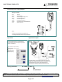
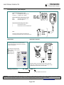
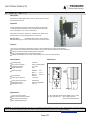
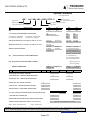
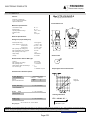
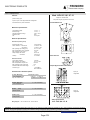
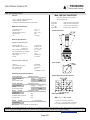
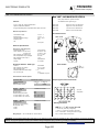
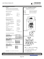
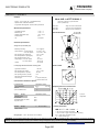
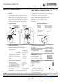
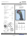
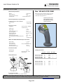
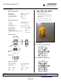
TECNORD
ELECTRONIC PRODUCTS
a Delta Power Company
SECTION/Description
Pages
Micro Processor based PWM Drivers
665
Electronic Joysticks and Switches
672
WARNING: The specifications/application data shown in our catalogs and data sheets are intended only as a general guide for the product described
(herein). Any specific application should not be undertaken without independent study, evaluation, and testing for suitability.
Phone: (815) 397-6628
Fax: (815) 397-2526
Page 663
E-mail: [email protected]
Page 664
TECNORD
ELECTRONIC PRODUCTS
a Delta Power Company
Micro Processor based PWM Drivers
Model
Page
EC-PWM-A1-MPC1-P
666
EC-PWM-A1-MPC1-D
668
EC-PWM-A1-MPC1-E
670
WARNING: The specifications/application data shown in our catalogs and data sheets are intended only as a general guide for the product described
(herein). Any specific application should not be undertaken without independent study, evaluation, and testing for suitability.
Phone: (815) 397-6628
Fax: (815) 397-2526
Page 665
E-mail: [email protected]
TECNORD
ELECTRONIC PRODUCTS
a Delta Power Company
EC - PWM - A1 - MPC1 - P
Description
Micro-processor based PWM electronic driver for remote control of a single
proportional solenoid valve.
Operation
The EC-PWM-MPC1 Proportional Valve driver supplies a solenoid with
a PWM (Pulse Width Modulated) current proportional to the input signal
from a potentiometer, PLC or other control systems
Adjustments of "Imin/Imax", "Ramp time", "Deadband" and "Dither" can be
effected directly from a key-pad integrated on the front panel
Mounting option:
panel-mounting style with INPUT/OUTPUT
multi-core sheathed cable
Features
The current in the solenoid is independent of change in the coil resistance and in supply voltage variations.
The inherent superimposed dither frequency helps to overcome friction and stiction effects in the controlled device.
Supply line is protected against reversed polarity and load dump.
Input is protected against short circuits to GND and supply.
Output is protected against short circuits, reversed polarity, over-current and over-temperature.
Specifications
Dimensions
Operating voltage:
Max current consumption:
Operating temperature:
Degree of protection:
8.5-30 Vdc
100mA (no load applied)
-25 / +85 °C
IP 67
Analog input signal:
Input impedance:
Typical ctrl pot resistance:
Standard:
0-5 V
Option 1:
0-10 V
Option 2:
0-20 mA
50k Ohm
2 - 47k Ohm
Current output range (PWM):
PWM dither frequency:
Adjustable ramp time:
100-3000 mA
55-200 Hz (adjustable)
0.05 - 5 s
Applications
Primary applications are the control of non-feedback
pressure and flow proportional valves to attain smooth
acceleration/deceleration and fine-metering control of linear
and rotary actuators
WARNING: The specifications/application data shown in our catalogs and data sheets are intended only as a general guide for the product described
(herein). Any specific application should not be undertaken without independent study, evaluation, and testing for suitability.
Phone: (815) 397-6628
Fax: (815) 397-2526
Page 666
E-mail: [email protected]
TECNORD
ELECTRONIC PRODUCTS
a Delta Power Company
Circuit board pinout - Wiring diagram
Wiring Color Codes
Blue
Brown
Red
Yellow
Gray
White
Green
Pink
+Battery
-Battery (GND)
Command signal supply (+5V)
Command signal in
Command signal GND
Proportional coil output
Proportional coil current feedback line
Spare / Not used
Fuse
A 5A fuse must be inserted on the BLUE wire
connecting the EC-MPC1 driver to the power source.
Adjustments
Application example
The following adjustments can be made directly
from the front key-pad by selecting the 3-pushpins
in various combinations:
Imin (minimum output current)
Imax (maximum output current)
Ramp-up time
Ramp-down time
Dither frequency
Remote operation of a proportional flow control valve from
single axis / unidirectional control lever incorporating a rotary
potentiometer and a center / power-off switch for the
energizing of an auxiliary solenoid-operated dump valve.
Ordering Information:
EC - PWM - A1 - MPC1 - P
A- = Adjustable
C = circuit board only
P = panel mounting
WARNING: The specifications/application data shown in our catalogs and data sheets are intended only as a general guide for the product described
(herein). Any specific application should not be undertaken without independent study, evaluation, and testing for suitability.
Phone: (815) 397-6628
Fax: (815) 397-2526
Page 667
E-mail: [email protected]
TECNORD
ELECTRONIC PRODUCTS
a Delta Power Company
EC - PWM - A1 - MPC1 - D
Description
Micro-processor based PWM electronic driver for remote control of a single
proportional solenoid valve.
Operation
The EC-PWM-MPC1-D Proportional Valve driver supplies a solenoid with
a PWM (Pulse Width Modulated) current proportional to the input signal
from a potentiometer, PLC or other control systems
Adjustments of "Imin/Imax", "Ramp time", "Deadband" and "Dither" can be
effected directly from a key-pad integrated on the front panel
Mounting option:
Female DIN 43650 socket on valve's side and
sheathed exit cable to connect to power source and remote control devices
Features
The current in the solenoid is independent of change in the coil resistance and in supply voltage variations.
The inherent superimposed dither frequency helps to overcome friction and stiction effects in the controlled device.
Supply line is protected against reversed polarity and load dump.
Input is protected against short circuits to GND and supply.
Output is protected against short circuits, reversed polarity, over-current and over-temperature.
Specifications
Dimensions
Operating voltage:
Max current consumption:
Operating temperature:
Degree of protection:
8.5-30 Vdc
100mA (no load applied)
-25 / +85 °C
IP 67
Analog input signal:
Input impedance:
Typical ctrl pot resistance:
Standard:
0-5 V
Option 1:
0-10 V
Option 2:
0-20 mA
50k Ohm
2 - 47k Ohm
Current output range (PWM):
PWM dither frequency:
Adjustable ramp time:
100-3000 mA
55-200 Hz (adjustable)
0.05 - 5 s
Applications
12 Vdc and 24 Vdc systems
Stable control of proportional valves
High resolution (10 bits) control
Field - adjustable applications
WARNING: The specifications/application data shown in our catalogs and data sheets are intended only as a general guide for the product described
(herein). Any specific application should not be undertaken without independent study, evaluation, and testing for suitability.
Phone: (815) 397-6628
Fax: (815) 397-2526
Page 668
E-mail: [email protected]
TECNORD
ELECTRONIC PRODUCTS
a Delta Power Company
Circuit board pinout - Wiring diagram
Power Supply Wiring Color Codes
Blue
(+) Positive from Power Source
Yell./Green (-) Negative from (GND)
Remote Potentiometer Wiring Color Codes
Black
Command signal supply (+5V)
Brown
Command signal in
Proportional Valves Wiring Color Codes
1
Proportional coil output
2
Proportional coil current feedback line
Fuse
A 5A fuse must be inserted on the BLUE wire
connecting the EC-MPC1 driver to the power source.
Adjustments
Application example
The following adjustments can be made directly
from the front key-pad by selecting the 3-pushpins
in various combinations:
Imin (minimum output current)
Imax (maximum output current)
Ramp-up time
Ramp-down time
Dither frequency
Remote operation of a proportional flow control valve from
single axis / unidirectional control lever incorporating a rotary
potentiometer and a center / power-off switch
Ordering Information:
EC - PWM - A1 - MPC1 - D
D = DIN 43650 socket connector
A- = Adjustable
WARNING: The specifications/application data shown in our catalogs and data sheets are intended only as a general guide for the product described
(herein). Any specific application should not be undertaken without independent study, evaluation, and testing for suitability.
Phone: (815) 397-6628
Fax: (815) 397-2526
Page 669
E-mail: [email protected]
TECNORD
ELECTRONIC PRODUCTS
a Delta Power Company
EC - PWM - A1 - MPC1 - E
Description
Micro-processor based PWM electronic driver for remote control of a single
proportional solenoid valve.
Operation
The EC-PWM-MPC1-D Proportional Valve driver supplies a solenoid with
a PWM (Pulse Width Modulated) current proportional to the input signal
from a potentiometer, PLC or other control systems
Adjustments of "Imin/Imax", "Ramp time", "Deadband" and "Dither" can be
effected directly from a key-pad integrated on the front panel
Mounting option:
Female DIN 43650 socket on valve's side and
Male DIN 43650 plug to connect to power source and remote control devices
Features
The current in the solenoid is independent of change in the coil resistance and in supply voltage variations.
The inherent superimposed dither frequency helps to overcome friction and stiction effects in the controlled device.
Supply line is protected against reversed polarity and load dump.
Input is protected against short circuits to GND and supply.
Output is protected against short circuits, reversed polarity, over-current and over-temperature.
Specifications
Dimensions
Operating voltage:
Max current consumption:
Operating temperature:
Degree of protection:
8.5-30 Vdc
100mA (no load applied)
-25 / +85 °C
IP 67
Analog input signal:
Input impedance:
Typical ctrl pot resistance:
Standard:
0-5 V
Option 1:
0-10 V
Option 2:
0-20 mA
50k Ohm
2 - 47k Ohm
Current output range (PWM):
PWM dither frequency:
Adjustable ramp time:
100-3000 mA
55-200 Hz (adjustable)
0.05 - 5 s
Applications
12 Vdc and 24 Vdc systems
Stable control of proportional valves
High resolution (10 bits) control
Field - adjustable applications
A : EN 175301-803 Socket (Ex DIN 43650) (To Prop. Valve)
B : EN 175301-803 Plug
(from Voltage supply and
Remote Control Potentiometer)
WARNING: The specifications/application data shown in our catalogs and data sheets are intended only as a general guide for the product described
(herein). Any specific application should not be undertaken without independent study, evaluation, and testing for suitability.
Phone: (815) 397-6628
Fax: (815) 397-2526
Page 670
E-mail: [email protected]
TECNORD
ELECTRONIC PRODUCTS
a Delta Power Company
Circuit board pinout - Wiring diagram
Adjustments
Application example
The following adjustments can be made directly
from the front key-pad by selecting the 3-pushpins
in various combinations:
Imin (minimum output current)
Imax (maximum output current)
Ramp-up time
Ramp-down time
Dither frequency
Remote operation of a proportional flow control valve from a
single axis / unidirectional control lever incorporating a rotary
potentiometer and a center / power-off switch
Ordering Information:
EC - PWM - A1 - MPC1 - E
D = DIN 43650 socket connector
A- = Adjustable
WARNING: The specifications/application data shown in our catalogs and data sheets are intended only as a general guide for the product described
(herein). Any specific application should not be undertaken without independent study, evaluation, and testing for suitability.
Phone: (815) 397-6628
Fax: (815) 397-2526
Page 671
E-mail: [email protected]
TECNORD
ELECTRONIC PRODUCTS
a Delta Power Company
Electronic Joysticks and Switches
Model/Description
Page
Joystick Model Codes
674
FTC-L1S/A0-IP-0
676
FTC-L2S/E0-IP-0
677
FTC-L2S/N0-IP-0
678
JLP-L2S/Q0-IP-D
679
JMF-L2S/F0-IC/0100
680
JMF-L4C/NN-IC/0200
681
JMF-L4C/FF-IE/A1P9/1PRS-0
682
JMF-L4C/NN-IE/A1P9/1PRS-0
683
JMF-L4C/NN-MG/A1P9/2PRS-0
684
Continued Next Page…
WARNING: The specifications/application data shown in our catalogs and data sheets are intended only as a general guide for the product described
(herein). Any specific application should not be undertaken without independent study, evaluation, and testing for suitability.
Phone: (815) 397-6628
Fax: (815) 397-2526
Page 672
E-mail: [email protected]
TECNORD
ELECTRONIC PRODUCTS
a Delta Power Company
JMF-L4C/NN-MG/A2P9/2FPR
685
JHD-L4C/TT-IC/0100-3
686
JHD-L4C/TT-MG/A2P9/2FPR-3
687
JHD-L4C/TT-MG/A1P9/2PRS-3
688
MG-A8P9-0000
689
MG-A2P9-2PRS
690
MG-A2P9-2FPR
691
MG-A4P9-1FPR-1PWM
692
PRS-L2S-S0-0-0
693
FPR-L2S-SNCH
694
WARNING: The specifications/application data shown in our catalogs and data sheets are intended only as a general guide for the product described
(herein). Any specific application should not be undertaken without independent study, evaluation, and testing for suitability.
Phone: (815) 397-6628
Fax: (815) 397-2526
Page 673
E-mail: [email protected]
TECNORD
ELECTRONIC PRODUCTS
a Delta Power Company
Joystick Model Codes
JOYSTICKS
Proportional Control Levers - Joystick Controllers - Ergonomic Handles
MINI Series Control Levers
JLP Series / Low profile control levers
JMF Series multi-functions Joystick Controllers
JHD Series multi-functions Joystick Controllers
IE Series Ergonomic Grips
MG Series Ergonomic Grips
FPR - Series proportional Roller Switches
PRS Series Proportional Rocker Switches
WARNING: The specifications/application data shown in our catalogs and data sheets are intended only as a general guide for the product described
(herein). Any specific application should not be undertaken without independent study, evaluation, and testing for suitability.
Phone: (815) 397-6628
Fax: (815) 397-2526
Page 674
E-mail: [email protected]
TECNORD
ELECTRONIC PRODUCTS
a Delta Power Company
Joystick Controllers
Cross Reference Table
JMF - L4C / MN - MG / A2P9 / 1FPR - 0
Connector type
Family & Type
K-K / Analog controls on handle
Main body configuration
Z-Z / ON-OFF controls on handle
Y-Y/X-X axes analog control configuration
Type of grip
Tab1
FAMILY AND TYPE
SIZE
JLP
JMF
JHD
Mini
Mini
Large
Large
L1S
L2S
Y-Y / X-X AXES & LEVER MOVEMENTS CONFIGURATION
L1S= Single Axis / Unidirectional
L2S= Single axis / Bidirectional
FTC
L1S
L2S
L4C
L4D
3&4-pin track
3-pin rotary
4-pin rotary
3-pin track
4-pin track
2 at center
2 at center
2 at center
IP=Paddle
IL= Low Profile / No controls
IC=Cylindrical / ON-OFF ctrls
IE= E-Type / ON-OFF & Analog
MG=Multi F / ON-OFF & Analog
L4C=Dual axes / Cross movement
L4D= Multi-axes / All diagonals
ANALOG CTRL DEVICES ON Y-Y/X-X AXES (See TAB 2 for ref. codes)
3-pin rotary
4-pin rotary
SWITCHED OUTPUTS ON Y-Y / X-X AXES
1 at center
2 at center
(See TAB 2 for ref. codes)
IP=Paddle
IC= Round.
HANDLES & GRIPS DESIGNATION:
Z-Z
L1S
L2S
L4C
L4D
L2S
On-off push buttons on IE and MG handles
A = 3A Dead Man lever
P9 = 3 Amp NO push buttons
AP= 200 mA NO push buttons
K-K Proportional controls IE and MG on handles
PRS= Prop Rocker pot
FPR= Prop. Roller pot
OUTPUT CONNECTORS
Tab2
0=None
2=Dubox
1=AMP(pot only)
POTENTIOMETERS & SWITCHED COMBINATIONS
S=40%Vin
S= 50%Vin
0=None
3= Exit cable
1=AMP(Pot only) 4= Deutsch
S= 80%Vin
S=90%Vin
3-PINS ROTARY POT. /ANALOG TRACK ONLY
A
D
3- PINS ROTARY POT. / 1 NEUTRAL-CENTER SWITCH (EMC)*
B
E
3-PINS ROTARY POT. / 2 DIRECTIONAL SWITCHES (EMC)*
C
F
S=100%Vin
4-PINS ROTARY POT. /ANALOG TRACK ONLY
G
L
4- PINS ROT. POT. / 1 NEUTRAL-CENTER SWITCH (EMC)*
H
M
4-PINS ROTARY POT. / 2 DIRECTIONAL SWITCHES (EMC)*
I
N
S= 75%Vin
3 & 4 PINS W/ ANALOG & SWITCHED OUTPUTS RESISTIVE TRACKS (RTR)
S= 80%Vin
Q
S=100%Vin
R
3 - PINS ANALOG W/ SWITCHES (RTR)
O
S
4-PINS W/ ANALOG & SWITCHED OUTPUTS RESISTIVE TRACKS (RTR)
P
T
3-PINS HALL EFFECT SENSOR ( Mod. FPR Prop. roller switch only):
(EMC)* = Electro - Mechanical Contact
U=
Special 0.5 -4.5 V output signal / 2.5 V at rest
(RTR)** = Resistive Track
WARNING: The specifications/application data shown in our catalogs and data sheets are intended only as a general guide for the product described
(herein). Any specific application should not be undertaken without independent study, evaluation, and testing for suitability.
Phone: (815) 397-6628
Fax: (815) 397-2526
Page 675
E-mail: [email protected]
TECNORD
ELECTRONIC PRODUCTS
a Delta Power Company
FTC-L1S/A0-IP-0
Mod. FTC-L1S/A0-IP-0
Features
Mini / Fingertip proportional control lever
. Single Axis / Unidirectional
. 3- Pins Rotary Potentiometers
. Optional Enable Switch
Overall Dimensions
Mechanical Specifications
. Lever deflection angle:
. Electrical angle:
. Operating temperature range:
. Protection class:
. Life:
50° +/- 1°
50° +/- 1°
-25°C / + 80°C
IP 65
3 mill cycles
Electrical Specifications
Analog track (3-pins Rotary Pot)
. Electrical power rating:
0.25 W @ 25°C
. Ohmic resistance: / A=50% of Vin
1 k ohm +/- 20%
/ D=90% of Vin
2.5 k ohm +/- 20%
/ D=90% of Vin
. Max. operating input voltage (Vin):
5 k ohm +/-20%
48 V or +/-24V
. Min. load impedance on pin 2 (Signal)
50 k ohm
. Max. operating current on pin 2
1 mA
. Output voltage
See GRAPH 1
. Linearity
2% or better
Panel Cut-Out
Neutral Position Switch / EMC* type
. Contacts
. Max. operating input voltage
. Max. operating current
. Neutral position switch threshold angle:
Silver Plated
48 V or +/-24V
1.5 A/inductive
+ 4°
. Pot. connector type:
none
1= AMP Modu / 4 poles
Output Signal Control Characteristic
Potentiometer & Switches Options
Y-Y Axis (Main body)
Pot.'s & Switches
3-pin Pot
3-pin Pot & Neutral Switch
X-X Axis (Main body)
REFERENCE CODES
S=50% Vin
S=90% Vin
A(Std)
D
3-pins pot.
B
E
configuration
0 = NOT AVAILABLE
Pot.'s & Switches
Z-Z Axis
(Grip)
0 = NOT AVAILABLE
ON-OFF controls
Ordering Information
0 = NOT AVAILABLE
K-K Axis (Grip)
FTC - L1S/A0 - IP - *
Analog Controls
n0 = no exit connector
Wiring Diagram:
refer to SM-FTC-L2S Service Manual
1= AMP Modu / 4 poles
WARNING: The specifications/application data shown in our catalogs and data sheets are intended only as a general guide for the product described
(herein). Any specific application should not be undertaken without independent study, evaluation, and testing for suitability.
Phone: (815) 397-6628
Fax: (815) 397-2526
Page 676
E-mail: [email protected]
TECNORD
ELECTRONIC PRODUCTS
a Delta Power Company
FTC-L2S/E0-IP-0
Mod. FTC- L2S /E0 - IP - 0
Features
Mini / Fingertip proportional control lever
. Single Axis / Bi-Directional
. 3- Pins Rotary Potentiometers
. Optional Center/Power-off or Bi-Directional Switches
Overall Dimensions
Mechanical Specifications
. Lever deflection angle:
+/- 25° +/- 1°
. Electrical angle:
+/-25° +/- 1°
. Operating temperature range:
. Protection class:
. Life:
-25°C / + 80°C
IP 65
3 mill cycles
Electrical Specifications
Analog track ( 3-Pins Rotary Pot )
. Electrical power rating:
0.25 W @ 25°C
. Ohmic resistance: / A=50% of Vin
1 k ohm +/- 20%
/ D=90% of Vin
2.5 k ohm +/- 20%
/ D=90% of Vin (Std)
. Max. operating input voltage (Vin):
5 k ohm +/-20%
48 V or +/-24V
. Min. load impedance on pin 2 (Signal)
50 k ohm
. Max. operating current on pin 2
1 mA
. Output voltage
See GRAPH 1
. Linearity
2% or better
Panel Cut-Out
Center/Power- off & Directional Switches / EMC* type
. Contacts
. Max. operating input voltage
. Max. operating current
. Directional switches threshold angle:
. Pot. connector type:
Silver Plated
48 V or +/-24V
1.5 A/inductive
+/- 4°
none
1= AMP Modu / 4 poles
Output Signal Control Characteristic
Potentiometer & Switches Options
Y-Y Axis (Main body)
REFERENCE CODES
Pot.'s & Switches
S=50% Vin
S=90% Vin
3-pin Pot
A
D
3-pin Pot & Center Switch
B
E(Std)
3-pin Pot & Bi-Dir. Switch
C
F
X-X Axis (Main body)
4-pins pot.
configuration
0 = NOT AVAILABLE
Pot.'s & Switches
Z-Z Axis
(Grip)
0 = NOT AVAILABLE
ON-OFF controls
Ordering Information
0 = NOT AVAILABLE
K-K Axis (Grip)
Mod. FTC - L2S /E0 - IP - *
Analog Controls
0 = no exit connector
Wiring Diagram:
refer to SM-FTC-L2S Service Manual
1= AMP Modu / 4 poles
WARNING: The specifications/application data shown in our catalogs and data sheets are intended only as a general guide for the product described
(herein). Any specific application should not be undertaken without independent study, evaluation, and testing for suitability.
Phone: (815) 397-6628
Fax: (815) 397-2526
Page 677
E-mail: [email protected]
TECNORD
ELECTRONIC PRODUCTS
a Delta Power Company
FTC-L2S/N0-IP-0
Mod. FTC- L2S / N 0 - IP - 0
Features
Mini / Fingertip proportional control lever
. Panel mounting style
. 4- Pins - Center Tap Rotary Potentiometer
. Optional Center/Power-off or Bi-Directional Switches
Mechanical Specifications
Overall Dimensions
. Lever deflection angle:
+/- 25° +/- 1°
. Electrical angle:
+/-25° +/- 1°
. Operating temperature range:
-25°C / + 85°C
. Protection class:
IP 65
. Life:
3 mill cycles
Electrical Specifications
Analog track ( 4-Pins Rotary Pot )
. Electrical power rating:
0.25 W @ 25°C
. Ohmic resistance: / G=40% of Vin
10 k ohm +/- 20%
/ L=100% of Vin
. Max. operating input voltage (Vin):
48 V or +/-24V
5 k ohm +/- 20%
. Min. load impedance on pin 2 (Signal)
50 k ohm
. Max. operating current on pin 2
1 mA
. Output voltage
See GRAPH 1
. Linearity
2% or better
Center/Power- off & Directional Switches / EMC* type
. Contacts
Panel Cut-Out
Silver Plated
. Max. operating input voltage
48 V or +/-24V
. Max. operating current
. Directional switches threshold angle:
1.5 A/inductive
+/- 4°
. Pot. connector type:
none
1= AMP Modu / 4 poles
Potentiometers & Switches Options
Output Signal Control Characteristic
Y-Y Axis (Main body)
Pot.'s & Switches
4-pin Pot
4-pin Pot & Center Switch
4-pin Pot & Bi-Dir. Switch
REFERENCE CODES
S=40% Vin
S=100% Vin
G
L
H
M
I
N (Std)
X-X Axis (Main body)
Pot.'s & Switches
0 = NOT AVAILABLE
Z-Z Axis
0 = NOT AVAILABLE
(Grip)
ON-OFF controls
Ordering Information
0 = NOT AVAILABLE
K-K Axis (Grip)
Mod. FTC - L2S / N0 - IP - *
Analog Controls
Wiring Diagram:
refer to SM-FTC-L2S Service Manual
0 = no exit connector
1= AMP Modu / 4 poles
WARNING: The specifications/application data shown in our catalogs and data sheets are intended only as a general guide for the product described
(herein). Any specific application should not be undertaken without independent study, evaluation, and testing for suitability.
Phone: (815) 397-6628
Fax: (815) 397-2526
Page 678
E-mail: [email protected]
TECNORD
ELECTRONIC PRODUCTS
a Delta Power Company
JLP-L2S/Q0-IP-D
Mod. JLP-L2S / Q0 - IP - D
Features
Single Axis / Bi-directional
Low profile / Fingertip proportional control lever
. Panel mounting style
. 3 pins & 4 pins / center tap potentiometer configuration
Overall Dimensions
. 2 directional center / power-off switches
Mechanical Specifications
. Lever deflection angle:
. Electrical angle:
. Operating temperature range:
. Protection class:
. Life:
+/- 32° +/- 1°
+/- 30° +/- 1°
-25°C / + 85°C
IP 65
3 mill cycles
Electrical Specifications
Potentiometer (Analog Track)
. Electrical power rating:
. Ohmic resistance : / 080 version
0.25 W @ 25°C
5 k ohm +/- 20%
/ 100 version
. Max. operating input voltage (Vin):
. Min. load impedance on pin 5 (Signal)
. Max. operating current on pin 5
. Output voltage / 080 version
/ 100 version
. Linearity
4 k ohm +/- 20%
48 V or +/-24V
50 k ohm
1 mA
80% of Vin
100% of Vin
Panel Cut-Out
2% or better
Directional Switches
. Typical track resistance:
. Max. operating input voltage
. Min. load impedance on pins 2&3 :
. Max. operating current on pins 2&3
150 Ohm
48 V or +/-24V
50 k ohm
1 mA
. Directional switches threshold angle:
. Connector type:
Output Signal Control Characteristic
+/- 4°
7 pin DUBOX
Mod. 76382.407
Potentiometer & Switches Options
Y-Y Axis (Main body)
Pot.'s & Switches
3-4pin Pot & Bi-Dir Switch
X-X Axis (Main body)
3-pins pot.
configuration
REFERENCE CODES
S=80% Vin
S=100% Vin
Q
R
0 = NOT AVAILABLE
Pot.'s & Switches
Z-Z Axis
(Grip)
0 = NOT AVAILABLE
ON-OFF controls
4-pins pot.
configuration
0 = NOT AVAILABLE
K-K Axis (Grip)
Analog Controls
Ordering Information
Wiring Diagram:
JLP - L2S / Q0 - IP - D
refer to SM-JLP-L2S Service Manual
WARNING: The specifications/application data shown in our catalogs and data sheets are intended only as a general guide for the product described
(herein). Any specific application should not be undertaken without independent study, evaluation, and testing for suitability.
Phone: (815) 397-6628
Fax: (815) 397-2526
Page 679
E-mail: [email protected]
TECNORD
ELECTRONIC PRODUCTS
a Delta Power Company
JMF-L2S/F0-IC/0100
Mod JMF-L2S/F0-IC/0100
Features
Heavy Duty / Multi-Axis Joystick Controller
. 3 pins Rotary Potentiometers
with IC Cylindrical Grip
. Optional Bi-directional Switches
. Cylindrical grip with DEAD MAN button or Rocker Switch
Option L1S
Mechanical Specifications
. Lever deflection angle:
+/- 25° +/- 1°
. Electrical angle:
. Operating temperature range:
. Protection class:
+/- 25° +/- 1°
-25°C / + 80°C
IP 65
. Life:
3 mill cycles
Single axis control / Uni-Directional
Option L2S
Single axis control / Bi-directional
Option L4C
Option L4D
Cross axis control / Bi-directional
Multi-axis control / Bi-directional
Overall Dimensions
Electrical Specifications
Analog track ( 3-Pins Rotary Pot )
. Electrical power rating:
. Ohmic resistance: / A=50% of Vin
/ D=90% of Vin
0.25 W @ 25°C
1 k ohm +/- 20%
2.5 k ohm +/- 20%
/ D=90% of Vin (Std)
. Max. operating input voltage (Vin):
. Min. load impedance on pin 2 (Signal)
. Max. operating current on pin 2
. Output voltage
. Linearity
5 k ohm +/-20%
48 V or +/-24V
50 k ohm
1 mA
See GRAPHS
2% or better
Directional Switches / EMC* type
Panel Cut-Out
. Contacts
Silver Plated
. Max. operating input voltage
. Max. operating current
. Pot. connector type:
48 V or +/-24V
3 A/ Inductive
none
1= AMP Mode / 4 poles
Potentiometers & Switches Options
Output Signal Control Characteristic
Y-Y Axis (Main body)
Pot.'s & Switches
3-pin Pot
3-pin Pot & Bi-Dir Switch
REFERENCE CODES
S=50% Vin
A
C
S=90% Vin
D
F (Std)
X-X Axis (Main body)
Pot.'s & Switches
3-pin Pot
3-pin Pot & Bi-Dir Switch
REFERENCE CODES
S=50% Vin
S=90% Vin
A
D
C
F (Std)
Z-Z Axis
(IC Grip)
ON-OFF controls
No push button
REFERENCE CODES
0000
Top NO push button
0100
Top rocker switch
0200
Ordering Information
JMF - L** / °° - IC / z z z z
K-K Axis
(IC Grip)
Analog Controls
0 = NOT AVAILABLE
** = 1S /2S /4C /4D (main body configuration)
°° = AA / CC / DD / FF (type of pots on main body)
Wiring Diagram:
refer to SM-JMF-L4C Service Manual
z z z z = 0000 /0100/0200 (push buttons on grip)
WARNING: The specifications/application data shown in our catalogs and data sheets are intended only as a general guide for the product described
(herein). Any specific application should not be undertaken without independent study, evaluation, and testing for suitability.
Phone: (815) 397-6628
Fax: (815) 397-2526
Page 680
E-mail: [email protected]
TECNORD
ELECTRONIC PRODUCTS
a Delta Power Company
JMF-L4C/NN-IC/0200
Mod. JMF-L4C /NN-IC/0200
Features
Heavy Duty / Multi-Axis Joystick Controller
. 4- Pins - Center Tap Rotary Potentiometers
with IC Cylindrical Grip
. Optional Bi-Directional Switches
Option L1S
. Cylindrical grip with DEAD MAN button or Rocker Switch
Mechanical Specifications
. Lever deflection angle:
+/- 25° +/- 1°
. Electrical angle:
. Operating temperature range:
. Protection class:
. Life:
+/- 25° +/- 1°
-25°C / + 80°C
IP 65
3 mill cycles
Single axis control / Uni-Directional
Option L2S
Single axis control / Bi-directional
Option L4C
Cross axis control / Bi-directional
Option L4D
Multi-axis control / Bi-directional
Overall Dimensions
Electrical Specifications
Analog track ( 4-Pins Rotary Pot )
. Electrical power rating:
0.25 W @ 25°C
. Ohmic resistance: / G=40% of Vin
10 k ohm +/- 20%
/ L=100% of Vin
. Max. operating input voltage (Vin):
48 V or +/-24V
5 k ohm +/- 20%
. Min. load impedance on pin 2 (Signal)
50 k ohm
. Max. operating current on pin 2
1 mA
. Output voltage
See GRAPHS
. Linearity
2% or better
Directional Switches / EMC* type
Panel Cut-Out
. Contacts
Silver Plated
. Max. operating input voltage
48 V or +/-24V
. Max. operating current
3 A/ Inductive
. Pot. connector type:
none
1= AMP Modu / 4 poles
Potentiometers & Switches Options
Output Signal Control Characteristic
Y-Y Axis (Main body)
Pot.'s & Switches
4-pin Pot
4-pin Pot & Bi-Dir. Switch
REFERENCE CODES
S=40% Vin
S=100% Vin
G
L
I
N (Std)
X-X Axis (Main body)
REFERENCE CODES
Pot.'s & Switches
4-pin Pot
4-pin Pot & Bi-Dir. Switch
Z-Z Axis
(IC Grip)
ON-OFF controls
S=40% Vin
G
I
REFERENCE CODES
No push button
Top NORM. OPEN push button
0000
0100
Top rocker switch
0200
K-K Axis
(IC Grip)
Analog Controls
Wiring Diagram:
S=100% Vin
L
N (Std)
Ordering Information
JMF - L** / °° -IC / z z z z
0 = NOT AVAILABLE
** = 2S /4C /4D (main body configuration)
°° = GG / I I / L L / N N (type of pots on main body)
z z z z= 0000 /0100/0200 (push buttons on grip)
refer to SM-JMF-L4C Service Manual
WARNING: The specifications/application data shown in our catalogs and data sheets are intended only as a general guide for the product described
(herein). Any specific application should not be undertaken without independent study, evaluation, and testing for suitability.
Phone: (815) 397-6628
Fax: (815) 397-2526
Page 681
E-mail: [email protected]
TECNORD
ELECTRONIC PRODUCTS
a Delta Power Company
JMF-L4C/FF-IE/A1P9/1PRS-0
Mod. JMF - L4C/FF-IE/A1P9/1PRS-0
Features
Heavy Duty / Multi-Axis Joystick Controller
. 3 pins Rotary Potentiometers
with IE Multi-Function ergonomic grip
. Optional Bi-Directional Switches
Option L1S :
. IE type handle
Mechanical Specifications
. Lever deflection angle:
+/- 25° +/- 1°
. Electrical angle:
. Operating temperature range:
. Protection class:
+/- 25° +/- 1°
-25°C / + 80°C
IP 65
. Life:
3 mill cycles
Single axis control / Uni-Directional
Option L2S
Single axis control / Bi-directional
Option L4C
Cross axis control / Bi-directional
Option L4D
Multi-axis control / Bi-directional
Overall Dimensions
Electrical Specifications
Analog track ( 3-Pins Rotary Pot )
. Electrical power rating:
0.25 W @ 25°C
. Ohmic resistance: / A=50% of Vin
1 k ohm +/- 20%
/ D=90% of Vin
2.5 k ohm +/- 20%
/ D=90% of Vin (Std)
. Max. operating input voltage (Vin):
5 k ohm +/-20%
48 V or +/-24V
. Min. load impedance on pin 2 (Signal)
50 k ohm
. Max. operating current on pin 2
1 mA
. Output voltage
See GRAPHS
. Linearity
2% or better
Directional Switches / EMC* type
Panel Cut-Out
. Contacts
Silver Plated
. Max. operating input voltage
48 V or +/-24V
. Max. operating current
. Directional switches threshold angle:
3 A/ Inductive
+/- 4°
. Pot. connector type:
none
1= AMP Modu / 4 poles
Potentiometers & Switches Options
REFERENCE CODES
( Y-Y & X-X Axis)
Pot.'s & Switches
S=50% Vin
3-pin Pot
3-pin Pot & Bi-Dir Switch
Z-Z Axis
Output Signal Control Characteristic
(IE Grip)
A
C
S=90% Vin
D
F (Std)
REFERENCE CODES
ON-OFF controls
No push buttons
Side DEAD MAN push button
Side & Front panel
0000
A000
1-2-3 push buttons / P9 - 3 Amp
1-2-3 push buttons / AP - 200 mA
01P9 - 02P9 - 03P9
01AP -02AP -03AP
K-K Axis
(IE Grip)
REFERENCE CODES
Ordering Information
Analog Controls
No PRS (Prop. Rocker Switch)
0000
No.FPR (Prop. roller)
1 x PRS
1x FPR
0000
1PRS
1FPR
Wiring Diagram:
JMF - L** / °° -IE / z z z z / k k k k
** = 1S /2S /4C /4D (main body configuration)
°° = AA / CC / DD / FF (type of pots on main body)
z z z z = 01P9 /02P9 /…./A3AP (push buttons on grip)
k k k k = 1PRS/2PRS/1FPR/2FPR
refer to SM-JMF-L4C Service Manual
WARNING: The specifications/application data shown in our catalogs and data sheets are intended only as a general guide for the product described
(herein). Any specific application should not be undertaken without independent study, evaluation, and testing for suitability.
Phone: (815) 397-6628
Fax: (815) 397-2526
Page 682
E-mail: [email protected]
TECNORD
ELECTRONIC PRODUCTS
a Delta Power Company
JMF-L4C/NN-IE/A1P9/1PRS-0
Mod. JMF - L4C/NN-IE/A1P9/1PRS-0
Heavy Duty / Multi-Axis Joystick Controller
Features
with IE Multi-Function ergonomic grip
. 4- Pins - Center Tap Rotary Potentiometers
Option L1S :
Single axis control / Uni-Directional
. Optional Bi-Directional Switches
Option L2S
Single axis control / Bi-directional
. IE type handle Designed to be operated with the palm of the hand
Option L4C
Cross axis control / Bi-directional
Option L4D
Multi-axis control / Bi-directional
Mechanical Specifications
Overall Dimensions
. Lever deflection angle:
. Electrical angle:
. Operating temperature range:
. Protection class:
+/- 25° +/- 1°
+/- 25° +/- 1°
-25°C / + 80°C
IP 65
. Life:
3 mill cycles
Electrical Specifications
Analog track ( 4-Pins Rotary Pot )
. Electrical power rating:
. Ohmic resistance: / G=40% of Vin
/ L=100% of Vin
. Max. operating input voltage (Vin):
. Min. load impedance on pin 2 (Signal)
0.25 W @ 25°C
10 k ohm +/- 20%
5 k ohm +/- 20%
48 V or +/-24V
50 k ohm
. Max. operating current on pin 2
. Output voltage
1 mA
See GRAPHS
. Linearity
2% or better
Directional Switches / EMC* type
. Contacts
. Max. operating input voltage
. Max. operating current
. Directional switches threshold angle:
. Pot. connector type:
Panel Cut-Out
Silver Plated
48 V or +/-24V
3 A/ Inductive
+/- 4°
none
1= AMP Modu / 4 poles
Potentiometers & Switches Options
( Y-Y & X-X Axis)
Z-Z Axis
Output Signal Control Characteristic
REFERENCE CODES
Pot.'s & Switches
4-pin Pot
4-pin Pot & Bi-Dir. Switch
(IE Grip)
S=40% Vin
G
I
S=100% Vin
L
N (Std)
REFERENCE CODES
ON-OFF controls
4-pins pot
No push buttons
0000
Side DEAD MAN push button
A000
1-2-3 push buttons / P9 - 3 Amp
01P9 - 02P9 - 03P9
1-2-3 push buttons / AP - 200 mA
01AP -02AP -03AP
K-K Axis
(IE Grip)
Analog Controls
configuration
REFERENCE CODES
No PRS (Prop. Rocker Switch)
No FPR (Prop. roller)
0000
0000
1 x PRS
1 x FPR
1PRS
1FPR
Ordering Information
JMF - L** / °° -IE / z z z z / k k k k
** = 2S /4C /4D (main body configuration)
°° = GG / I I / L L/ N N (type of pots on main body)
z z z z = 01P9 /02P9 /…./A3AP (push buttons on grip)
Wiring Diagram:
refer to SM-JMF-L4C Service Manual
k k k k = 1PRS / 2PRS / 1FPR / 2FPR
WARNING: The specifications/application data shown in our catalogs and data sheets are intended only as a general guide for the product described
(herein). Any specific application should not be undertaken without independent study, evaluation, and testing for suitability.
Phone: (815) 397-6628
Fax: (815) 397-2526
Page 683
E-mail: [email protected]
TECNORD
ELECTRONIC PRODUCTS
a Delta Power Company
JMF-L4C/NN-MG/A1P9/2PRS-0
Mod. JMF - L4C/NN-MG/A1P9/2PRS-0
Features
. 3-pins and 4- Pins/ Center Tap Rotary Potentiometers
Heavy Duty / Multi-Axis Joystick Controller
. Optional Center / power-off and Bi-Directional Switches
with MG Multi-Function ergonomic grip
. MG- type ergonomic grip with PRS / Prop. Rocker Switches
Mechanical Specifications
. Lever deflection angle:
+/- 25° +/- 1°
. Electrical angle:
+/- 25° +/- 1°
. Operating temperature range:
-25°C / + 80°C
. Protection class:
IP 65
. Life:
3 mill cycles
Option L1S :
Single axis control / Uni-Directional
Option L2S
Single axis control / Bi-directional
Option L4C
Cross axis control / Bi-directional
Option L4D
Multi-axis control / Bi-directional
Overall Dimensions
Electrical Specifications
Analog track ( 4-Pins Rotary Pot )
. Electrical power rating:
0.25 W @ 25°C
. Ohmic resistance: / G=40% of Vin
10 k ohm +/- 20%
/ L=100% of Vin
. Max. operating input voltage (Vin):
48 V or +/-24V
5 k ohm +/- 20%
. Min. load impedance on pin 2 (Signal)
50 k ohm
. Max. operating current on pin 2
1 mA
. Output voltage
See GRAPHS
. Linearity
2% or better
Directional Switches / EMC* type
. Contacts
Silver Plated
. Max. operating input voltage
48 V or +/-24V
. Max. operating current
. Directional switches threshold angle:
3 A/ Inductive
+/- 4°
. Pot. connector type:
Panel Cut-Out
0 = none
1= AMP Modu / 4 poles
Potentiometers & Switches Options
REFERENCE CODES
( Y-Y & X-X Axis)
Pot.'s & Switches
S=40% Vin
S=100% Vin
Output Signal Control Characteristic
4-pin Pot
G
L
4-pin Pot & Bi-Dir. Switch
I
N (Std)
Z-Z Axis
(MG Grip)
REFERENCE CODES
ON-OFF controls
No push buttons
0000
Side DEAD MAN push button
A000
1-2-3….8 push buttons / P9 - 3 Amp
01P9 - 02P9 - …08P9
4-pins pot
1-2-3…8 push buttons / AP - 200 mA
01AP -02AP -…08AP
configuration
K-K Axis
(MG Grip)
REFERENCE CODES
Analog Controls
No PRS (Prop. Rocker Switch)
1 x PRS
0000
1PRS
2 x PRS
3 x PRS
2PRS
3PRS
Wiring Diagram:
Ordering Information
JMF - L** / °° -MG / z z z z / k k k k - *
** = 2S /4C /4D (main body configuration)
°° = GG / I I / L L/ N N (type of 4-pins pots on main body)
z z z z = 01P9 /08P9 /…./A8AP (push buttons on grip)
k k k k = 1PRS / 2PRS / 3PRS
* = 0 / 1 (Connector type option)
refer to SM-JMF-L4C Service Manual
WARNING: The specifications/application data shown in our catalogs and data sheets are intended only as a general guide for the product described
(herein). Any specific application should not be undertaken without independent study, evaluation, and testing for suitability.
Phone: (815) 397-6628
Fax: (815) 397-2526
Page 684
E-mail: [email protected]
TECNORD
ELECTRONIC PRODUCTS
a Delta Power Company
JMF-L4C/NN-MG/A2P9/2FPR
Mod. JMF - L4C/NN-MG/A2P9/2FPR
Features:
. 3-pins and 4- Pins/ Center Tap Rotary Potentiometers
. Optional Center / power-off and Bi-Directional Switches
. MG- type ergonomic grip with FPR Prop. Rollers
Heavy Duty / Multi-Axis Joystick Controller
with MG Multi-Function ergonomic grip
Mechanical Specifications
. Lever deflection angle:
+/- 25° +/- 1°
. Electrical angle:
+/- 25° +/- 1°
. Operating temperature range:
-25°C / + 80°C
. Protection class:
IP 65
. Life:
3 mill cycles
Option L2S
Single axis control / Bi-directional
Option L4C
Cross axis control / Bi-directional
Option L4D
Multi-axis control / Bi-directional
Overall Dimensions
Electrical Specifications
Analog track ( 4-Pins Rotary Pot )
. Electrical power rating:
. Ohmic resistance: / G=40% of Vin
/ L=100% of Vin
. Max. operating input voltage (Vin):
0.25 W @ 25°C
10 k ohm +/- 20%
5 k ohm +/- 20%
48 V or +/-24V
. Min. load impedance on pin 2 (Signal)
50 k ohm
. Max. operating current on pin 2
1 mA
. Output voltage
See GRAPHS
. Linearity
2% or better
Directional Switches / EMC* type
. Contacts
Silver Plated
. Max. operating input voltage
48 V or +/-24V
. Max. operating current
. Directional switches threshold angle:
3 A/ Inductive
+/- 4°
. Connectors:
0 = none (Std)
Panel Cut-Out
Potentiometers & Switches Options
( Y-Y & X-X Axis)
REFERENCE CODES
Pot.'s & Switches
S=40% Vin
S=100% Vin
4-pin Pot
G
L
4-pin Pot & Bi-Dir. Switch
I
N (Std)
Z-Z Axis
(MG Grip)
Output Signal Control Characteristic
REFERENCE CODES
ON-OFF controls
No push buttons
0000
Side DEAD MAN push button
A000
4-pins pot
1-2-3….8 push buttons / P9 - 3 Amp
01P9 - 02P9 - …08P9
configuration
1-2-3…8 push buttons / AP - 200 mA
01AP -02AP -…08AP
K-K Axis
(MG Grip)
REFERENCE CODES
Analog output (Hall effect sensor / 1-5 V output signal)
No FPR (Prop. Roller)
0000
1 x FPR
1FPR
2 x FPR
2FPR
3 x FPR
3FPR
Ordering Information
JMF - L** / °° -MG / z z z z / k k k k
** = 2S /4C /4D (main body configuration)
Wiring Diagram:
refer to SM-JMF-L4C Service Manual
°° = GG / I I / L L/ N N (type of 4-pins pots on main body)
z z z z = 01P9 /08P9 /…./A8AP (push buttons on grip)
k k k k = 1FPR / 2FPR /3FPR
WARNING: The specifications/application data shown in our catalogs and data sheets are intended only as a general guide for the product described
(herein). Any specific application should not be undertaken without independent study, evaluation, and testing for suitability.
Phone: (815) 397-6628
Fax: (815) 397-2526
Page 685
E-mail: [email protected]
TECNORD
ELECTRONIC PRODUCTS
a Delta Power Company
JHD-L4C/TT-IC/0100-3
Features:
Mod. JHD - L4C/TT-IC/0100- 3
. 3-pins or 4- Pins / Center Tap / RTR (Resistive track)
Heavy Duty / Multi-Axis Joystick Controller
. Optional Center Bi-Directional Switches
with IC Cylindrical Grip
. IC type handle with single/NO and rocker switch push buttons
Option L2S
Mechanical Specifications
. Lever deflection angle:
+/- 25° +/- 1°
. Electrical angle:
+/- 25° +/- 1°
. Operating temperature range:
-25°C / + 80°C
. Protection class:
IP 65
. Life:
3 mill cycles
Single axis control / Bi-directional
Option L4C
Cross axis control / Bi-directional
Option L4D
Multi-axis control / Bi-directional
Overall Dimensions
Electrical Specifications
Analog track ( 4-Pins Rotary Pot )
. Electrical power rating:
0.25 W @ 25°C
. Ohmic resistance: / O & P Pot.Options
5 k ohm +/- 20%
/ S & T Pot. Options
. Max. operating input voltage (Vin):
48 V or +/-24V
3.75 k ohm +/- 20%
. Min. load impedance on pin 5 (Signal)
50 k ohm
. Max. operating current on pin 5
1 mA
. Output voltage / O & P Pot. Options
75% of Vin
/ S & T Pot. Options
100% of Vin
. Linearity
2% or better
Panel Cut-Out
Low amperage directional switches on base joystick
. Typical track resistance:
. Max. operating input voltage
. Min. load impedance on pins 2&3 :
. Max. operating current on pins 2&3
. Directional switches threshold angle:
150 Ohm
48 V or +/-24V
50 k ohm
1 mA
+/- 4°
3 =16 poles cable (Std)
. Connector type:
4= Deutsch HD14-9-16P
Potentiometers & Switches Options
( Y-Y & X-X Axis)
REFERENCE CODES
Pot.'s & Switches
O/P=75
S/T=100%
3-pin Pot
O
S
4-pin Pot & Bi-Dir Switch
P
T
Z-Z Axis
(IC Grip)
Output Signal Control Characteristic
REFERENCE CODES
4-pins pot
ON-OFF controls
configuration
No push button
0000
Top NORM. OPEN push button
0100
Top rocker switch
0200
K-K Axis
(IC Grip)
0 = NOT AVAILABLE
Ordering Information
Analog Controls
JHD - L** / °° - IC / z z z z - *
** = 2S /4C /4D (main body configuration)
°° = OO / PP / SS/ TT (type of 3/4-pins pots on main body)
Wiring Diagram:
refer to SM-JHD-L4C Service Manual
z z z z = 0100 /0200 (push buttons on grip)
* = 3 / 4 (Exit connector type)
WARNING: The specifications/application data shown in our catalogs and data sheets are intended only as a general guide for the product described
(herein). Any specific application should not be undertaken without independent study, evaluation, and testing for suitability.
Phone: (815) 397-6628
Fax: (815) 397-2526
Page 686
E-mail: [email protected]
TECNORD
ELECTRONIC PRODUCTS
a Delta Power Company
JHD-L4C/TT-MG/A2P9/2FPR-3
Mod. JHD-L4C/TT-MG/A2P9/2FPR-3
Heavy Duty / Multi-Axis Joystick Controller
Features
with MG Multi-Function ergonomic grip and FPR Prop. Rollers
Mod. JHD-L4C joystick controller has been designed for use in Mobile
The M G range of ergonomic handles adopted for this
Equipment applications in conjunction with TECNORD MMS electronic
line of joysticks controllers integrates the widest variety of
drivers to generate analogue and switched signals proportional to the
ON-OFF push buttons and PROPORTIONAL ROLLER switches.
lever deflection angle for the remote control of electro-hydraulic PROPOR-
When coupled with a two - axis base-joystick, up to 3-4-5
TIONAL or ON-OFF hydraulic valves of any type and make. A center tap
analog axes and 2 to 9 ON-OFF push buttons can be integrated
analog track provides an accurate voltage reference for the center position
in the same joystick package.
Overall dimensions
Mechanical Specifications
. Option L2S
Single axis control / Bi-dir.
. Option L4C
Cross axis control / Bi-dir.
. Option L4D
Multi-axis control / Bi-dir.
. Operating temp. range:
. Protection class:
-25°C / +80°C
IP 65
. Life:
3 mill cycles
Wiring diagram
Panel Cut-out
Electrical Specifications
Potentiometers & Switches Options
Potentiometers (Analog Tracks on base jstck)
( Y-Y & X-X)
REFERENCE CODES
Base prop. ctrls / Joystick
O/P=75%
S/T=100%
. Electrical power rating:
0.25 W @ 25°C
3-pins Pot
O
S
. Ohmic resistance: / O & P Pot.Options
5 k ohm +/- 20%
4-pins Pot & Bi-Dir Switch
P
T
/ S & T Pot. Options
. Max. operating input voltage (Vin):
3.75 k ohm +/- 20%
48 V or +/-24V
Z-Z Axis
. Min. load impedance on pin 5 (Signal)
50 k ohm
ON-OFF Controls
. Max. operating current on pin 5
1 mA
No push buttons
0000
. Output voltage / O & P Pot. Options
75% of Vin
Side DEAD MAN push button
A000
100% of Vin
1-2-3….8 push buttons / P9 - 3 Amp
01P9 - 02P9 - …08P9
2% or better
1-2-3…8 push buttons / AP - 200 mA
01AP -02AP -…08AP
/ S & T Pot. Options
. Linearity
Directional Switches on base joystick
K-K Axis
(MG Grip)
(MG Grip)
REFERENCE CODES
REFERENCE CODES
Analog output (Hall effect sensor / 1-5 V output signal
. Typical track resistance:
. Max. operating input voltage
. Min. load impedance on pins 2&3 :
. Max. operating current on pins 2&3
. Directional switches threshold angle:
150 Ohm
48 V or +/-24V
50 k ohm
1 mA
No FPR (Prop. roller)
0000
1 x FPR
1FPR
2 x FPR
2FPR
3 x FPR
3FPR
+/- 4°
Ordering Information
. Connector type:
3 =16 poles cable (Std)
. Counter connector p/n:
4= Deutsch HD14-9-16P
JHD - L** / °° - MG / z z z z - k k k k - *
Deutsch HD16-P-16S
** = 2S /4C /4D (main body configuration)
°° = OO / PP / SS/ TT (type of 3/4-pins pots on main body)
z z z z = P9 / AP (push buttons on grip)
Wiring Diagram:
refer to SM-JHD-L4C Service Manual
k k k k = 1FPR / 2FPR /3FPR (Prop. Rollers on Grip front)
* = 3 / 4 (Exit connector type)
WARNING: The specifications/application data shown in our catalogs and data sheets are intended only as a general guide for the product described
(herein). Any specific application should not be undertaken without independent study, evaluation, and testing for suitability.
Phone: (815) 397-6628
Fax: (815) 397-2526
Page 687
E-mail: [email protected]
TECNORD
ELECTRONIC PRODUCTS
a Delta Power Company
JHD-L4C/TT-MG/A1P9/2PRS-3
Mod. JHD-L4C/TT-MG/A1P9/2PRS - 3
Heavy Duty / Multi-Axis Joystick Controller
Features
with MG Multi-Function ergonomic grip and PRS Prop. Rocker Switches
Mod. JHD-L4C joystick controller has been designed for use in
The M G range of ergonomic handles adopted for
Mobile Equipment applications in conjunction with TECNORD
M M S electronic drivers to generate analogue and switched
variety of ON-OFF push buttons and PROPORTIONAL rocker
this line of joysticks controllers integrates the widest
signals proportional to the lever deflection angle for the remote
and roller
control of electro-hydraulic PROPORTIONAL or ON-OFF hydraulic
base joystick, up to 3-4-5 analog axes and 2 to 9
switches. When coupled with a two - axis
valves of any type and Make. A center tap on the analog track
ON-OFF push buttons can be integrated in the same
provides an accurate voltage reference for the center position.
joystick package.
Overall dimensions
PRS- Proportional
Rocker Switch
Mechanical Specifications
P9 - Push Button
. Option L2S
Single axis control / Bi-dir.
. Option L4C
Cross axis control / Bi-dir.
. Option L4D
Multi-axis control / Bi-dir.
. Operating temp. range:
-25°C / +80°C
. Protection class:
IP 65
. Life:
3 mill cycles
Panel Cut-out
Electrical Specifications
Potentiometers & Switches Options
Potentiometers (Analog Tracks on base jstck & PRS)
( Y-Y & X-X)
REFERENCE CODES
Base prop. ctrls / Joystick
O/P=75%
S/T=100%
. Electrical power rating:
0.25 W @ 25°C
3-pin Pot & Bi-Dir Switch
O
S
. Ohmic resistance: / O & P Pot.Options
5 k ohm +/- 20%
4-pin Pot & Bi-Dir Switch
P
T
/ S & T Pot. Options
. Max. operating input voltage (Vin):
2,5 k ohm +/- 20%
48 V or +/-24V
Z-Z Axis
. Min. load impedance on pin 5 (Signal)
50 k ohm
ON-OFF Controls
. Max. operating current on pin 5
1 mA
No push buttons
0000
. Output voltage / O & P Pot. Options
75% of Vin
Side DEAD MAN push button
A000
/ S & T Pot. Options
. Linearity
(MG Grip)
REFERENCE CODES
100% of Vin
1-2-3….8 push buttons / P9 - 3 Amp
01P9 - 02P9 - …08P9
2% or better
1-2-3…8 push buttons / AP - 200 mA
01AP -02AP -…08AP
Directional Switches on base joystick
K-K Axis
(MG Grip)
REFERENCE CODES
Analog Controls
. Typical track resistance:
. Max. operating input voltage
. Min. load impedance on pins 2&3 :
. Max. operating current on pins 2&3
. Directional switches threshold angle:
150 Ohm
48 V or +/-24V
50 k ohm
1 mA
No PRS (Prop. Rocker Switch)
0000
1 x PRS
1PRS
2 x PRS
2PRS
3 x PRS
3PRS
+/- 4°
JHD - L** / °° - MG / z z z z - k k k k - *
. Connector type:
Wiring Diagram:
3 =16 poles cable (Std)
4= Deutsch HD14-9-16P
refer to SM-JHD-L4C-MG Service Manual
** = 2S /4C /4D (main body configuration)
°° = OO / PP / SS/ TT (type of 3/4-pins pots on main body)
z z z z = P9 / AP (push buttons on grip)
k k k k = 1 PRS / 2 PRS /3 PRS (Prop. Rocker Switches on Grip front)
* = 3 / 4 (Exit connector type)
WARNING: The specifications/application data shown in our catalogs and data sheets are intended only as a general guide for the product described
(herein). Any specific application should not be undertaken without independent study, evaluation, and testing for suitability.
Phone: (815) 397-6628
Fax: (815) 397-2526
Page 688
E-mail: [email protected]
TECNORD
ELECTRONIC PRODUCTS
a Delta Power Company
MG-A8P9-0000
Mod. MG-A8P9-0000
Mechanical Specifications:
Multi-function ergonomic handle with ON-OFF push buttons
. Material:
Thermoplastic
- Optimum ergonomic design
. Color:
Black
- High performance switches
. Operating temperature range:
-25 °C / + 85°C
- Easy adaptability to existing
joystick control levers
. Connecting hub:
Female thread / M14 x1.5
Electrical Specifications of push buttons
A - Dead man front lever:
. Rated amperage
3 Amp inductive
P9 - Push buttons
. No. of push buttons on front panel:
up to 8
. No. of push buttons on rear edge:
up to 3
. Rated amperage
3 Amp inductive
. Life:
> 100,000 cycles
. Available colors:
red
Blue
yellow
black
green
white
AP - Push buttons
. No. of push buttons on front panel:
up to 8
. No. of push buttons on rear edge:
up to 3
. Typical Amperage rating:
200 mA
. Life:
> 500,000 cycles
Pre-wired exit cable:
250 mm
Overall Dimensions
Ordering Information
D-man P/B
Front P/B
Rear P/B
MG-0000-0000
0
0
0
MG-A000-0000
yes
0
0
MG-A1P9-0000:
yes
1xP9
0
MG-A2P9-0000:
yes
2xP9
0
MG-A8P9-0000:
yes
8xP9
0
MG-A8P9-R1P9
yes
8xP9
1xP9
MG-A8P9-R2P9
yes
8xP9
2xP9
MG-A8P9-R3P9
yes
8xP9
3xP9
MG-A1AP -0000
yes
1xAP
0
MG-A2AP-0000
yes
2xAP
0
MG-A8AP-R1AP
yes
8xAP
1xAP
MG-A8AP-R2AP
yes
8xAP
2xAP
MG-A8AP-R3AP
yes
8xAP
3xAP
Mod. MG-A8P9-R3P9
* Rubber gather and retainer ring are supplied separately
WARNING: The specifications/application data shown in our catalogs and data sheets are intended only as a general guide for the product described
(herein). Any specific application should not be undertaken without independent study, evaluation, and testing for suitability.
Phone: (815) 397-6628
Fax: (815) 397-2526
Page 689
E-mail: [email protected]
TECNORD
ELECTRONIC PRODUCTS
a Delta Power Company
MG-A2P9-2PRS
Mod. MG-A2P9-2PRS
Mechanical Specifications:
. Material:
Thermoplastic
Multi-function ergonomic handle with ON-OFF push buttons
. Plastic handle color
Black
and PRS Proportional Rocker Switches
. Operating temperature range:
-25 °C / + 85°C
. Connecting joint:
Female thread / M14 x1.5
- Optimum ergonomic design
- High performance switches
- Easy adaptability to existing
joystick control levers
Electrical Specifications of push buttons
A / Dead man front lever & P9 / Push buttons
. Rated amperage
3 Amp inductive
. Life:
> 100,000 cycles
AP - Push buttons
. Rated amperage
200 mA
. Life:
> 500,000 cycles
PRS Proportional Rocker Switch
. Configuration:
3-pins resistive pot
4-pins / Center tap
2 x Center /Power-off switched outputs
. Rotation angle:
+/- 24°
. Resistive track power rating:
0.5 Watt @ 25°C
. Resistive track Ohmic resistance:
5 k Ohm +/- 20%
. Linearity
2%
. Vin (max)
48V or +/- 24V
. Rated output current of potentiometer:
1 mA
. Rated current of switched outputs:
1 mA
. Min resistive load on bidirectional switched outputs:
50 k Ohm
. Operating temperature range:
-25 °C / + 85°C
. Environmental protection degree (above panel):
IP67
. Life:
>1.000.000 cycles
Pre-wired exit cable:
250 mm
Ordering Information
D-man P/B
Overall Dimensions
Mod. MG-A2P9-2PR
Front P/B
Front PRS
MG-01P9-1PRS
0
1xP9
1
MG-A2P9-1PRS
yes
2xP9
1
MG-A3P9-1PRS
yes
3xP9
1
MG-A4P9-1PRS
yes
4xP9
1
2
MG-01P9-2PRS
0
1xP9
MG-A1P9-2PRS
yes
1xP9
2
MG-A2P9-2PRS
yes
2xP9
2
MG-0000-2PRS
0
0
2
MG-A000-2PRS
yes
0
2
MG-A000-3PRS
yes
0
3
MG-01AP-1PRS
0
1xAP
1
MG-A2AP-1PRS
yes
2xAP
1
MG-A3AP-1PRS
yes
3xAP
1
MG-A4AP-1PRS
yes
4xAP
1
MG-01AP-2PRS
0
1xAP
2
MG-A1AP-2PRS
yes
1xAP
2
MG-A2AP-2PRS
yes
2xAP
2
* Rubber gather and retainer ring are supplied separately
WARNING: The specifications/application data shown in our catalogs and data sheets are intended only as a general guide for the product described
(herein). Any specific application should not be undertaken without independent study, evaluation, and testing for suitability.
Phone: (815) 397-6628
Fax: (815) 397-2526
Page 690
E-mail: [email protected]
TECNORD
ELECTRONIC PRODUCTS
a Delta Power Company
MG-A2P9-2FPR
Mod. MG-A2P9-2FPR
Mechanical Specifications:
Multi-function ergonomic handle with ON-OFF push buttons
and FPR Proportional Rollers
. Material:
Thermoplastic
. Plastic handle color
Black
- Optimum ergonomic design
. Operating temperature range:
-25°C / + 85° C
- High performance switches
. Connecting joint:
Female thread / M14 x1.5
- Easy adaptability to existing
joystick control levers
Electrical Specifications of push buttons
A - Dead man front lever:
. Rated amperage
3 Amp inductive
. Life:
> 100,000 cycles
P9 - Push buttons
. Rated amperage
3 Amp inductive
. Life:
> 100,000 cycles
AP - Push buttons
. Rated amperage
200 mA
. Life:
> 500,000 cycles
FPR Proportional Roller
. Configuration:
3-pins connection / Hall Effect
contactless sensor
. Rotation angle
+/- 23°
. Supply voltage:
8-32 Vdc
. Current consumption at rest:
25 mA
. Signal output @ rest:
2.5 Vdc +/-0.0V
. Full output signal range:
0.5 - 4.5 V, +/-0.2V
. Rated output current:
1 mA
. Operating temperature range:
-25 °C / + 85°C
. Environmental protection degree (above panel):
IP67
. Life:
>5.000.000 cycles
Pre-wired exit cable:
250 mm
Ordering Information
D-man P/B
Overall Dimensions
Mod. MG-A000-3FPR
Front P/B
Front FPR
MG-01P9-1FPR
0
1xP9
1
MG-A2P9-1FPR
yes
2xP9
1
MG-A3P9-1FPR
yes
3xP9
1
MG-A4P9-1FPR
yes
4xP9
1
MG-01P9-2FPR
0
1xP9
2
MG-A1P9-2FPR
yes
1xP9
2
MG-A2P9-2FPR
yes
2xP9
2
2
MG-0000-2FPR
0
0
MG-A000-2FPR
yes
0
2
MG-A000-3FPR
yes
0
3
MG-01AP-1FPR
0
1xAP
1
MG-A2AP-1FPR
yes
2xAP
1
MG-A3AP-1FPR
yes
3xAP
1
MG-A4AP-1FPR
yes
4xAP
1
MG-01AP-2FPR
0
1xAP
2
MG-A1AP-2FPR
yes
1xAP
2
MG-A2AP-2FPR
yes
2xAP
2
* Rubber gather and retainer ring are supplied separately
WARNING: The specifications/application data shown in our catalogs and data sheets are intended only as a general guide for the product described
(herein). Any specific application should not be undertaken without independent study, evaluation, and testing for suitability.
Phone: (815) 397-6628
Fax: (815) 397-2526
Page 691
E-mail: [email protected]
TECNORD
ELECTRONIC PRODUCTS
a Delta Power Company
MG-A4P9-1FPR-1PWM
Mod. MG-A4P9-1FPR-1PWM
Mechanical Specifications:
. Material:
Thermoplastic
Multi-function ergonomic handle with ON-OFF push buttons,
. Plastic handle color
Black
1 x FPR Proportional Rollers and built-in PWM driver for
. Operating temperature range:
-25°C / + 85° C
a bidirectional / dual proportional coil
. Connecting joint:
Female thread / M14 x1.5
- Optimum ergonomic design
Electrical Specifications of push buttons
- High performance switches
- Easy adaptability to existing
joystick control levers
A/ Dead man front lever & P9/ Push Buttons
. Rated amperage
3 Amp inductive
. Life:
> 100,000 cycles
FPR Proportional Roller
. Configuration:
3-pins connection / Hall Effect
contactless sensor
. Rotation angle
+/- 23°
. Supply voltage:
8-32 Vdc
. Current consumption at rest:
25 mA
. Signal output @ rest:
2.5 Vdc +/-0.0V
. Full output signal range:
0.5 - 4.5 V, +/-0.2V
. Rated output current:
1 mA
. Operating temperature range:
-25 °C / + 85°C
. Environmental protection degree (above panel):
IP67
. Life:
>5.000.000 cycles
PWM - Pulse Width Modulated output current driver
. Supply voltage:
8 - 32 Volt
. Max. current draw:
100 mA
. Current output range:
. PWM dither frequency:
. Operating temperature range:
Factory set btw 0 and 1400 mA
100 Hz
-25°C/+85°C
Pre-wired exit cable:
. Standard length
. Wiring diagram:
Ordering Information
250 mm
Refer to MG-1FPR - PWM
Service Manual
D-man P/B
Overall Dimensions
Front P/B
FPR
PWM
MG-01P9-1FPR-1PWM
0
1xP9
1
1
MG-A2P9-1FPR-1PWM
yes
2xP9
1
1
MG-A3P9-1FPR-1PWM
yes
3xP9
1
1
MG-A4P9-1FPR-1PWM
yes
4xP9
1
1
MG-01AP-1FPR-1PWM
0
1xAP
1
1
MG-A2AP-1FPR-1PWM
yes
2xAP
1
1
MG-A3AP-1FPR-1PWM
yes
3xAP
1
1
MG-A4AP-1FPR-1PWM
yes
4xAP
1
1
Mod. MG-A4P9-1FPR-1PWM
* Rubber gather and retainer ring are supplied separately
WARNING: The specifications/application data shown in our catalogs and data sheets are intended only as a general guide for the product described
(herein). Any specific application should not be undertaken without independent study, evaluation, and testing for suitability.
Phone: (815) 397-6628
Fax: (815) 397-2526
Page 692
E-mail: [email protected]
TECNORD
ELECTRONIC PRODUCTS
a Delta Power Company
PRS-L2S-S0-0-0
Mod. PRS - L2S - S0 - 0 - 0
Mechanical Specifications:
. Main body material:
Acetyl resin / Teflon compound
Mini Proportional Rocker Switch with built-in
. Rubber gather material
EPDM / 35-45 shore - A
bidirectional switched outputs
. Rubber gather color
Black
. Operating temperature range:
-25°C / + 85° C
. Environmental protection
IP 66 (above panel)
. Life:
>1.000.000 cycles
- Optimum ergonomic design for panel-mounting
on remote control boxes and for the retrofitting
of joystick handles
Electrical Specifications
. Configuration:
- High performance resistive tracks
3-pins resistive pot. w/o directional switches
4-pins resistive pot. w/ bidirectional switches
. Mechanical rotation angle
+/- 24°
. Resistive track power rating:
0.5 Watt @ 25°C
. Resistive track Ohmic resistance:
5 k Ohm +/- 20%
. Linearity
2%
. Vin (max)
48V or +/- 24V
. Rated output current of potentiometer:
1 mA
. Rated current of switched outputs:
1 mA
. Min resistive load on bidirectional switched outputs:
50 k Ohm
. Operating temperature range:
-25 °C / + 85°C
. Pre-wired exit cable:
250 mm
Ordering Information
Electrical Schematic
3 - PINS / STD CONFIGURATION
P & T version
4-pins type
PRS - L2S - O0
3-pins pot - 75% of Vin / Bidir. switches
PRS - L2S - S0
3-pins pot - 100% of Vin / Bidir. switches
Overall Dimensions
4-PINS / CENTER TAP CONFIGURATION
Panel cut - out
PRS - L2S - P0
4-pins pot - 75% of Vin / Bidir. switches
PRS - L2S - T0
4-pins pot - 100% of Vin / Bidir. switches
Ordering Information
Mod. MG - L2S - ° ° - *
° ° = O / S (75%/ 100% 3-pins pot.) - P / T (75% / 100% 4 pin pots)
Q / R (80% / 100% 3 & 4 pins)
* = 0 / L (with or without mini-paddle)
WARNING: The specifications/application data shown in our catalogs and data sheets are intended only as a general guide for the product described
(herein). Any specific application should not be undertaken without independent study, evaluation, and testing for suitability.
Phone: (815) 397-6628
Fax: (815) 397-2526
Page 693
E-mail: [email protected]
TECNORD
ELECTRONIC PRODUCTS
a Delta Power Company
PRS-L2S-SNCH
Mod. FPR - L2S - SNCH
Mechanical Specifications:
. Main body material:
. Main body colour:
. Rubber gaither material
. Operating temperature range:
. Environmental protection
. Life:
- Mini Proportional Roller Switch with built-in
bidirectional switched outputs
Acetal resin & Teflon compound
Yellow
EPDM / 35-45 shore - A
-25°C / + 85° C
IP 68
>5.000.000 cycles
- Optimum ergonomic design for panel-mounting
on remote control boxes and for the retrofitting
of joystick handles
- High performance Hall Effect Sensor Circuitry
Electrical Specifications
- Single Channell and Twin Channell configurations
. Configuration:
3-pins connection / Hall Effect
contactless sensor
. Rotation angle
+/- 30°
. Supply voltage:
8-32 Vdc
. Current consumption at rest:
SNCH (S1 only)
15 mA
TWCH (S1/S2 9
25 mA
. Signal output @ rest:
2.5 Vdc +/-0.1V
. Full output signal range:
0.5 - 4.5 V, +/-0.2V
. Rated output current:
1 mA
. Operating temperature range:
-25 °C / + 85°C
. Environmental protection degree (above panel):
IP67
. Life:
>5.000.000 cycles
Overall Dimensions
Control Characteristic
FPR - L2S - SNCH - 0 (Single Channell)
Panel cut-out
FPR - L2S - TWCH - 0 (Twin Channell)
Electrical Connections:
FPR - L2S - SNCH- 0
FPR - L2S - TWCH - 0
(Single channell)
(Twin channell)
Yellow:
Orange:
Red:
Brown:
+ 5Vdc
(-) Ground
S1
not used
Yellow:
Orange:
Red:
Brown:
+ 5Vdc
(-) Ground
S1
S2
WARNING: The specifications/application data shown in our catalogs and data sheets are intended only as a general guide for the product described
(herein). Any specific application should not be undertaken without independent study, evaluation, and testing for suitability.
Phone: (815) 397-6628
Fax: (815) 397-2526
Page 694
E-mail: [email protected]