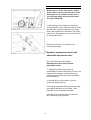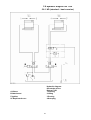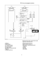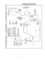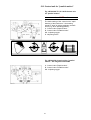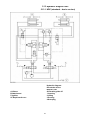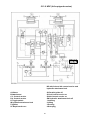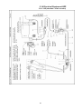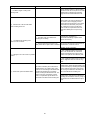
1
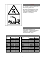
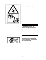
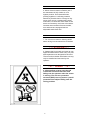
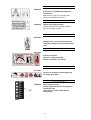
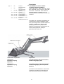
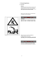
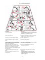
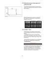
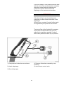
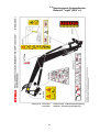
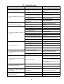
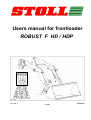
(2007 =>)
Users manual for frontloader
ROBUST F HD / HDP
Englisch
3311981 b
P 1359
STOLL ROBUST F HD / HDP
Table of contents
1
Before operating
2
General safety information and prevention of accidents
2.1
Safety decal (=> 2007)
2.2
Safety decal (2007 =>)
3
Technical data
4
Description
5
Practical Application
5.1
Operation
5.1.1 Operation
5.1.2 Operation
5.2
Hydraulic system
5.3
Attaching of drive-in loader unit
5.4
Removal of the drive-in front loader
5.5
Mechanical single lever control unit SLV (option available)
5.5.1 Type
5.5.2 Definition of working directions
5.5.3 Definition of actuating directions
5.5.4 Additional functions joystick buttons
5.5.5 Operation fast stroke device
5.6
Quick installation and removal of attachments
5.7
Hydraulic implement control with switchable fast-stroke valve
5.8
Hydraulic diagram HE + HD
5.8.1 HD (standard – basic version)
5.8.2 HD (full equipped version)
5.9
Electrical Equipment HD
5.9.1 HD (standard – basic version)
5.9.2 HD Fully equipped electric version with 2-pole socket
5.9.3 HD Fully equipped electric version with 7-pole socket
5.10 Toogle switch 3rd Control circuit
5.11 Hydraulic parallel guidance of the implements
5.11.1 Advantages of hydraulic parallel motion ( HS = Hydraulical Selfleveling )
5.11.2 Operation
5.11.3 Function
5.12 Control unit for "parallel motion"
5.13 Hydraulic diagram HDP
5.13.1 HDP (standard – basic version)
5.13.2 HDP (full equipped version)
5.14 Electrical Equipment HDP
5.14.1 HD (standard – basic version)
5.14.2 HDP Fully equipped electric version with 2-pole socket
5.14.3 HDP Fully equipped electric version with 7-pole socket
6
Ballasting the tractor during front loader operation
7
Service and maintenance
8
Safety and Prevention of Accidents
8.1
Driving on public roads
8.2
Allowed maximun load capacity of pallet fork tines
8.3
Comfort - Drive
9
Decalcomania
9.1
Decalcomania frontend loader Robust F "right"
9.2
Decalcomania frontendloader Robust F "left"
9.3
Decalcomania frontendloader Robust F "right" (2007 =>)
9.4
Decalcomania frontendloader Robust F "left" (2007 =>)
10
Troubleshooting
11
EC-Declaration of Conformity
page
3
5
12
13
14
16
18
18
19
20
21
22
23
26
26
27
27
28
29
30
31
33
33
34
35
35
36
37
38
39
39
40
42
43
44
44
45
46
46
47
48
49
50
53
53
54
54
56
56
57
58
59
60
62
1. Before operating
Prior to operating frontend loader
please read and observe the
operator's manual and all safety
instructions!
In this operating instruction booklet we have
marked all paragraphs which refer to your
safety with this sign.
Pass on all safety advices also to other users.
Operation in accordance with
specifications!
The STOLL frontend loader is built solely
for normal agricultural use (operated in
accordance with specifications).
It may only be operated with tools
especially provided by STOLL for this
purpose.
It may only be attached to field tractors and
other tractive machines for which it is
designed and offered by STOLL (intended
use).
Use of frontend loader Robust F for any
other purpose tan defined above is
considered as operation which is not in
accordance with specifications and is
undertaken as such at the owner's risk.
Observation of operation and maintenance
instructions specified by manufacturer shall
also be taken to the part of operation in
accordance with specifications.
The frontend loader Robust F may only be
operated, serviced and repaired by personnel
who are familiar with these functions and who
have been instructed of the inherent dangers.
3
-- ▲ -- DANGER -- ▲ -It is forbidden to approach within reach of
this machinery while in use.
All relevant accident prevention, safety,
health and street regulations must be
observed according general or local
regulations of user country.
-- ▲ -- CAUTION -- ▲ -STOLL must regretfully decline
responsibility for damage resulting from
unauthorised changes to loader or
equipment and any misuse.
Tightening torque for screws
class
screws
M8
M8x1
M10
M10x1,25
M12
M12x1,5
M12x1,25
M14
M14x1,5
M16
M16x1,5
M18
M18x2
M18x1,5
8.8
Nm (lb-ft)
23 (17)
25 (18)
46 (34)
49 (36)
80 (59)
84 (62)
88 (65)
130 (96)
138 (102)
190 (140)
210 (155)
270 (199)
280 (206)
300 (221)
10.9
Nm (lb-ft)
33 (24)
35 (26)
65 (48)
69 (51)
110 (81)
118 (87)
123 (91)
180 (133)
190 (140)
270 (199)
290 (214)
380 (280)
400 (295)
420 (310)
screws
M20
M20x2
M20x1,5
M22
M22x2
M22x1,5
M24
M24x2
M27
M27x2
M30
M30x2
5/8“UNC (normal)
5/8“UNF (fine)
3/4"UNC (normal)
3/4"UNF (fine)
4
class
8.8
10.9
Nm (lb-ft)
Nm (lb-ft)
380 (280)
530 (391)
400 (295)
560 (413)
420 (310)
590 (435)
510 (376)
720 (531)
540 (398)
750 (553)
560 (413)
790 (582)
630 (464)
890 (656)
680 (501)
950 (700)
930 (686)
1310 (966)
995 (733)
1400 (1032)
1260 (929)
1770 (1305)
1370 (1010)
1930 (1423)
175
200
380
420
(129)
(147)
(280)
(310)
245 (180)
280 (206)
530 (391)
590 (435)
2. General safety information and
prevention of accidents
Most accidents which occur in
agricultural enterprises are the result of
safety rules being disregarded by
personnel.
Safety precautions
A careful operator is the best operator.
Most accidents can be avoided by
observing certain precautions.
To help prevent accidents, read and take
the following precautions before working
or operating with the frontloader or
servicing it. Equipment should be
operated only by those who are
responsible and instructed to do so.
Safety decal 3449070a has to be affixed in
drivers visibility!
Throughout this manual you will
regognize text in italics, preceded by the
words NOTE, ATTENTION, IMPORTANT,
CAUTION, WARNING or DANGER.
Such text has the following significance:
Machine safety
-- ! -- NOTE -- ! -This text stresses a correct operating
technique or procedure.
-- ! -- ATTENTION -- ! -This text warns the operator of potential
machine damage if a certain procedure is
not followed.
-- ▲ -- IMPORTANT -- ▲ -This text informs the reader of something
that he needs to know to prevent minor
machine damage if a certain procedure is
not followed.
5
Personal Safety
-- ▲ -- CAUTION -- ▲ -The word CAUTION is used where a safe
behavioural practice, according to
operating and maintenance instrucions
and common safety practices will protect
the operator and others from accident
involvement.
-- ▲ -- WARNING -- ▲ -The word WARNING denotes a potential
or hidden hazard which could possibly
cause serious injury. It is used to warn
operators and others to exercise due
care and attention to avoid a surprise
accident with machinery.
-- ▲ -- DANGER -- ▲ -The word DANGER denotes a forbidden
practice in connection with a serious
hazard.
Failure to follow the CAUTION, WARNING
and DANGER instructions may result in
serious bodily injury or even death.
-- ▲ -- CAUTION -- ▲ -1. Front loaders may only be attached to
tractors equipped with a lockable
hydraulic system, otherwise it becomes
necessary to install a shut-off valve.
-- ▲ -- CAUTION -- ▲ -2. The hydraulic system must be locked
during travel on public roads and while
the tractor is parked.
6
-- ▲ -- DANGER -- ▲ -3. Never convey or raise people in a
bucket or other attachment!
-- ▲ -- CAUTION -- ▲ -4. The maximum roadspeed with
attached load beam is 25 km/h, the
maximum working speed is 10 km/h.
Check front tyres for correct loader
operation air pressures according tractor
user manual !
-- ▲ -- DANGER -- ▲ -5. Never carry out repair, cleaning or
lubricating jobs with raised load beam!
Lower or remove beam. Lower load beam
after completion of work.
7
-- ! -- ATTENTION -- ! -6. Never drive the tractor off with a jerk if
the attachment is fully loaden or in its
highest position. Drive downhill when
pushing together or collecting material,
whenever possible load in a trough or dip;
never drive across a gradient with raised
load beam; increase rear track width of the
tractor as necessary and never drive with a
narrower then standard front track width,
even with tractors equipped with an
adjustable width front axle.
-- ! -- ATTENTION -- ! -7. Do not turn the tractors steering wheel
when driving into the material to be loaded.
-- ! -- ATTENTION -- ! -8. Operate the front loader only with its own
approved attachments. Never carry out jobs
with implements not designed for the work.
The tool and the loader arm/loader unit may
only be installed and removed by the
operator.
-- ▲ -- DANGER -- ▲ -9. Lifting pallets or bales over the cab
creates an increased risk of the load
falling onto the operator when the tractor
is moving. The roll-over protection
structure (ROP) can only ensure a partial
protection from objects falling onto the
driving position.
8
Special tools such as pallet forks or bale
handling tools are designed in a way that
prevents the load from falling down onto
the tractor.
Stacking of bales is not allowed because
of the risk that upper bales could fall
down and injure persons.
The tip angle of the tool for loader
without selfleveling (HD typ) or if
selfleveling is deactivated (HDP type
special function) will be increase when
raising up the liftarm. The user has to
compensate this increase manually with
joystick to eleminate the risk of goods
falling down and of injuring persons..
-- ▲ -- DANGER -- ▲ -10. Sojourn within the working range
(3m) is prohibited.
Stay clear away of raised loader arms or
unsecured loads.
Please recognize and follow relevant
machine safety regulations for loader
work according DIN EN 12525/A1:2006.
9
-- ▲ -- DANGER -- ▲ -11. Travel with loaded bucket on public
streets is prohibited!
-- ▲ -- DANGER -- ▲ -12. Rules for prevention of accidents
issued by the professional associations
and organisations as well as the
regulations applying to construction and
use of any legally prescribed protective
devices must be observed at all times.
For transport and travelling on public
roads local country street regulations
have to be maintained.
-- ▲ -- CAUTION -- ▲ -13. Always store the loader on a solid
area and with the tool installed. Be sure
the prop stands are locked in a safe
position.
-- ▲ -- IMPORTANT -- ▲ -14. Good visibility is essential during
frontloader operation (clean cab
windows; no risk of dazzling; sufficient
lighting of the work area in the dark).
-- ▲ -- DANGER -- ▲ -15. Ensure that the front loader is a safe
distance away from overhead power
lines. Danger to life in case of contact!
10
-- ▲ -- DANGER -- ▲ -16. Liquids leaking under high pressure
(Diesel fuel, hydraulic oil) can penetrate
the skin and cause severe injury. When
injured see a doctor immediately!
Danger of infection!
-- ▲ -- CAUTION -- ▲ -17. Before the first use of the loader and
then at least once a year all hoses must
be checked by an expert worker for their
operational safety and replaced if
required. The time of use of the hoses
should not exceed six years including a
maximum storage time of two years. The
replacement hoses and pipings must
meet with the implement manufacturer's
technical standards!
-- ! -- ATTENTION -- ! -Installation Instruction!
Hydraulic pipes (pipes and screwed joints)
are ex works only unassembled pre mounted.
After final laying of pipes at the tractor all
screwed joints must be tightened and
retightened after first 5 working hours.!
-- ▲ -- CAUTION -- ▲ -18. When searching for leaks appropriate
aids should be used because of the
danger of injury.
-- ! -- ATTENTION -- ! -19. If there is installed any equipment at the
tractor, which may interfere with loaderarm,
tool or any attachement, it has to be
removed before executing loader work.
11
2.1 Safety decal
(=> 2007)
-- ! -- ATTENTION -- ! -3377500a
Danger of severe injury Only remove the
loader if a tool is fitted
-- ! -- ATTENTION -- ! -3377570a
Danger in the working area!
Do not allow anybody to come within the
machine's working area, particularly if
the equipment is raised.
12
2.2 Safety decal
(2007 =>)
-- ! -- ATTENTION -- ! -3310350a
Danger of severe injury Only remove the
loader if a tool is fitted
-- ! -- ATTENTION -- ! -3431550a
Danger in the working area
Do not allow anybody to come within the
machine's working area, particularly if
the equipment is raised.
13
-- ! -- ATTENTION -- ! -3430500a
Instructions for HYDRO-FIX hydraulic
connections
Method to be used for connection and
removal of HYDRO-FIX devices.
-- ▲ -- CAUTION -- ▲ -3430510a
Danger from high pressure!
Stop the engine and discharge residual
pressure from the system.
-- ! -- NOTE -- ! -3377220a
Lifting points - Connection points to be
used when lifting the loader without front
tools
-- ! -- ATTENTION -- ! -3375741b
Functions selector
Select O = rapid unloading
Select I = hydraulic 3rd service
-- ! -- ATTENTION -- ! -3411720b
Control for hydraulic selflevelling (only
for loader type HDP)
-- ! -- ATTENTION -- ! -3343590a
Tool coupling control
Sticker applied to the tool coupling bar;
coupling is safe
when side “A” is level with the tool
holder bush.
14
3. Technical data
WILHELM STOLL
Maschinenfabrik GmbH
Postfach 3, 38266 Lengede
Bahnhofsraße 21, 38268 Lengede
Telephone
+49 (5344)20-0
Telefax
+49 (5344)20-182
Telephone
+49 (5344)20-266
Telefax
+49 (5344)20-183
Telephone
+49 (5344)20-131
Telefax
+49 (5344)20-137
Manufacturer
Spare parts
Service
Dealer
Tractor
Type plate
Wilhelm Stoll Maschinenfabrik GmbH D 38268 Lengede
Type
S-No.
LIFTARM
765321
Robust F
30. 01
30F1HxSEFAMC100
Fabr-No.
1234567
weight
xxx kg
year 2007
Made in Germany / Fabriqué en Allemagne
Performence data
Function Code
suitably for loader
xx F x x NS xF Ax Cx xx
4
30 - 44 kW (40 - 60 PS)
30 - 55 kW (40 - 75 PS)
< 70 kW (95 PS)
59 - 96 kW (80 - 130 PS)
> 82 kW (110 PS)
x
Performence data
04 F x x NS
0x F x x NS
1x F x x NS
3x F x x NS
5x F x x NS
10-15
x
30-36
50-51
-
-
-
-
-
x
-
-
-
-
-
-
x
-
-
-
-
-
-
-
x
suitably for loader
Function Code
xx F x x HS xF Ax Cx xx
30 - 55 kW (40 - 75 PS)
< 70 kW (95 PS)
59 - 96 kW (80 - 130 PS)
> 82 kW (110 PS)
5-8
8
10-15
x
08 F x x HS
1x F x x HS
3x F x x HS
5x F x x HS
15
30-36
-
-
-
x
-
-
-
-
-
-
x
50-51
-
-
-
-
-
-
x
4. Description
Type: 4
HD
5
HD
8
HD - HDP
10/15 HD - HDP
30/31 HD - HDP
35/36 HD - HDP
50/51 HD - HDP
for tractors
up to 45 kW (60 HP)
for tractors
up to 51 kW (70 HP)
for tractors
up to 56 kW (75 HP)
for tractors
up to 70 kW (95 HP)
for tractors between
59 – 89 kW (80 – 120 HP)
for tractors between
66 – 96 kW (90 – 130 HP)
for tractors
exceeding 82 kW (110 HP)
THE RANGE OF "STOLL" FRONT
LOADERS, SERIES "ROBUST F"
Types 4 HD - 5 HD - 8 HD - 10/15 HD - 30/31
HD - 35/36 HD - 50 HD - 8 HDP - 10/15 HDP 30/31 HDP - 35/36 HDP - 50/51 HDP are
DRIVE-IN FRONT LOADERS, they are
absolutely uniform for all makes of tractor and
consist of:
The loader unit, completely assembled by the
manufacturers, ready for installation (boom
with quick-change frame, hydraulic implement
actuation, hydraulic rams, hydraulic lines,
parking legs and drive-in pillars), tractor
attachment components, front protection and
various hook implements, mainly for
agricultural and forestry use.
Loader main components:
Explanation:
Lifting arms
Implement coupling
Implement
Type HD Hydraulic implement actuation,
double-acting tipping rams.
Lifting arms
Implement coupling
Implement
Type HDP Hydraulic implement actuation,
double-acting tipping rams and parallel
guidance.
The liftarm are manufactured in a box section
construction according to the principle of a
beam with identical moment of resistance.
16
A quick-change frame for the effortless
installation and removal of the implements is
part of the standard delivery range of the
boom.
The complete unit is secured to the
attachment components by means of a
tensioning wedge.
The parking support legs are required for
installation and removal of the loader unit.
Installation or removal can be accomplished
by one person without bodily effort in 2 to 4
minutes.
-- ! -- ATTENTION -- ! --
You must have changed empty weight of
the tractor registered by the relevant
Technical Control Board!
As the front loader mounting parts are rigidly
fitted to the tractor, they involve a change of
the tractor empty weight which is subject to
registration according to C.&U.R.
It is therefore essential that the increased
empty weight of the tractor (without front
loader) is registered by the local authority in
the vehicle documents (registration certificate).
17
5. Practical Application
5.1 Operation
General
The usual tractor driver skill and a pronounced
empathy with the function of the front loader
suffice for first-class, fault-free operation. Good
front loader work soon becomes habit.
Nearly all front loader jobs can be carried out
in genuine one-man-operation.
-- ▲ -- DANGER -- ▲ -Sojourn within the working range is
prohibited.
Stay clear away of raised unsecured loads.
(Machine safety >> DIN EN 12525/A1:2006)
Adequate space should be available for
loading operations in the yard.
In the field the front loader/tractor requires wellsupporting ground, in the yard a paved surface.
-- ▲ -- CAUTION -- ▲ -The maximum roadspeed is 25 km/h, the
maximum working speed during loading
work with installed implements is 10 km/h.
18
-- ! -- ATTENTION -- ! -Do not turn the steering wheel while driving
into the material to be loaded, rather drivein straight ahead!
Avoid too rapid lowering and especially rearresting a load, which may result in shock
loads being imposed onto the front axle.
Beyond that, all accident prevention
regulations laid down by the agricultural
insurance association and the rules of the
C.&U.R. must be complied with.
5.1.1 Operation decal (=> 2007)
19
5.1.2 Operation decal (2007=>)
Installation
Removal
1. Unlock hand lever
Attention! Do not remove the loader unless
a bucket or attachment is fitted.
2. Drive tractor forward
1. Apply the tractor parking brake and lower the
loader until it is resting on the ground.
3. until the pins contact the glide rail jaw
2. unlock the hand lever
4. Stop the tractor and apply the parking
brake.
3. lower the parking stands
5. Relieve hydraulic system pressure (see
tractor operators manual) and connect Multi
Quick coupler and electrics.
4. Continue to lower the loader until the rear pins
are resting on the glide rails.
6. Raise the loader until the loader arm
5. Disconnect theMultiQuick coupler and
retaining pins are fully registered in the jaw
electrical connections.
Attention! Do not operate the bucket or
attachment cylinders until the loader arms are
securely locked.
7. Raise the loader and fold up the prop
stands
8. move the hand lever downwards to the
locked position
6. Reverse the tractor away from the loader
assembly.
Attention! Check the tightness of the
locking mechanism at regular intervals,
adjust if required.
20
5.2 Hydraulic system
Front loaders may only be attached to
agricultural tractors which are equipped with a
lockable hydraulic control unit. Otherwise it
becomes necessary to provide a shut-off valve
between control unit and the hydraulic line,
leading to the loader beam.
-- ▲ -- CAUTION -- ▲ -When traveling on roads, doing
maintenance or when loader is detached
the safety locking of control lever (Z) have
to be moved to the blocked position, or the
required hydraulic valve (shut-off valve or
Hydro-Fix) should be closed.
21
5.3 Attaching of drive-in loader unit
(figs. LHO1002A and LHO1003A)
-- ▲ -- DANGER -- ▲ -The loader arm/loader unit may only be
installed and removed by the opera tor.
(Fig. LHO1002A)
Unlatch gripping lever (1) and drive the tractor
forward into the parked loader beam, until the
pins (2) of the pillars contact the stop in the
arresting hook. Brake the tractor in this position
by applying the handbrake.
Connect the hydraulic line by means of the
couplings (Fig. LHO1005A) resp. Hydro-Fix
(Fig. LHO1004A).
Connection hydraulic pipes with hydraulic
flexible tubes:
1 Loader arm lower
2 Loader arm raise
3 Implement scoop
4 Implement dump
(Fig.LHO1003A)
Move control valve lever to position “Raise”,
until the pins (2) contact the arresting hooks
completely at both sides. Lift the loader beam,
until the bucket clears the ground completely.
Use gripping lever to lock.Fold the prop stands
swiftly against the loader arm and allow the
locking cam to catch into the slot of the prop
stand.
22
-- ! -- ATTENTION -- ! -After initial installation adjust locking device
(see fig. LHO1003A) as follows: Loosen nut
(4), adjust bolt (5) to ensure the tensioning
process commences in position (b) of the
gripping lever, which should be noticeable preloaded in position (c). Tighten locknut (4).
Bleed the hydraulic rams by lifting and lowering
the loader beam several times.
The locking mechanism has to be checked at
each attachment and removal as well as
occasionally if the frontloader remains
mounted on the tractor for a longer period.
Correct the setting if necessary.
5.4 Removal of the drive-in front loader
(Figs. LWP1076A and LHO1007A)
-- ▲ -- DANGER -- ▲ -The loader arm/loader unit may only be
installed and removed by the operator
-- ▲ -- DANGER -- ▲ -Do not park loader beam without attached
bucket or other implement, otherwise
danger of tipping over!
Lower balance beam without pressure up to
the ground.
Unlock gripping handle (1) and fold prop
stands down onto the ground.
Drive forward slightly, allow control unit thereby
to remain in position “Lower” until the pins (2)
glide out from the arresting hooks and lie on
the glide path (A). (Driving forward is omitted in
the case of double-acting hydraulic rams,
because the pins (2) will slip out of the
arresting hook through the retraction of the
hydraulic cylinders).
Drive backwards until the prop stands engage
and the pillar take off from the glide path (A).
23
Disconnect the hydraulic lines at the couplings
(see fig. LHO1025A resp. LHO1026A) and at
the electric cable. Fit dust cap and blanking
plug. Drive tractor out.
-- ▲ -- IMPORTANT -- ▲ -Loading and lightly raising the front loader
attachment as well as thorough lubrication of
the glide path A (see fig. LHO1006A) will
facilitate loosening the tensioning wedge (see
fig. LHO1003A).
Unfolding the prop stands
To fold out the prop stands, move their feet
sideways towards the tractor and at the same
time press them downward until the locking
cams come loose from the slots. Then unfold
the prop stands down to the ground
Prop stands are automatically locked in this
position by the spring-loaded support struts.Be
sure that the ground is solid enough.
24
Folding up the prop stands
To fold up the prop stands use one hand to
pull up the support strut against the resistance
of the integrated torsion spring in the direction
of arrow A and at the same time push the prop
stand in the direction of arrow D to prevent the
support strut from locking into engagement.
Pull the prop stand out of the locking area and
then move it swiftly against the loader arm.
-- ▲ -- DANGER -- ▲ -When handling the prop stand there is a
danger of injury by pinching. Keep hands
clear of the area between prop stand and
loader
Fold up the prop stand until it is locked by the
rubber spring catch. Grease the rubber spring
catches occasionally.
When installing and removing the loader arm
follow the instructions of the decal placed on
the loader arm pillar.
Hydro-Fix
-- ! -- ATTENTION -- ! -It is essential that the male and female
connectors of the Hydro-Fix hose couplers
are clean when the hoses are coupled.
Relieve all pressure from the hydraulic
system before coupling the hoses. Damage
to the seals could result if the hoses are
coupled under pressure .
25
5.5 Mechanical single lever control unit SLV
(option available)
Assembly instruction see A874-english
Stoll-ID-Nr: 3330580b.pdf
-- ! -- NOTE -- ! -5.5.1 Type
NIMCO WK-200 or compatible
EHS
Equipment EHS DW / DW
Extend of supply
Single lever control unit for FL with doubleacting beam-cylinders and double-acting
implement cylinders.
Items may depend from customer order
-- ! -- NOTE -- ! -On special request partner solutions are
available, implementing other joystick and
bowden cable variants or combined valve
stets.
Please find reference information on partner
service manual for technical details and
service parts informations which may variate
from Stoll specifications.
-- ! -- ATTENTION -- ! -To combine lift arm and tractor monted
bracket sets from different build years with
different electric sockets the following kits are
available:
Stoll-ID 3447220 KIT EL. 2-pol > 7-pol
with plug for liftarm side.
Stoll-ID 3447230 KIT EL. 2-pol > 7-pol
with 7-pol socket and adapter bracket for
tractor side
26
Later chapters (or Stoll document A1877 in
KIT) showing all relevant electric harness
diagramms for these alternatives. Please
allow only qualified service personal to do
these assembly work.
5.5.2 Definition of working directions
5.5.3 Definition of actuating directions
All hydraulic functions can be operated with one hand
only.
The entire ROBUST-series can, as an option, be
equipped with the single lever control for the
frontloader. High comfort of operation, simple but also
precise and safe control of the loader arm – all this
united in a single handy lever. The unit consists of the
control lever in the cab and the control valve with its
Bowden cables fitted outside to the frontloader
mounting. The four hydraulic couplings of the control
valve are situated in line which has several
advantages: The valve can be kept flat, it takes little
room and it doesn’t obstruct view to the front axle.
5 Grundfunktionen:
A frontloader - lift
B frontloader - lower
C attachment - scoop
D attachment - discharge
S frontloader - floating position
3 combined functions:
A-D lift + discharge
B-C lower + fill
B-D lower + discharge
27
-- ! -- NOTE -- ! -Combined functions are not possible with HDP
loaders!
With HD or HDPM Loaders only limited, we can
not proceed two “pressure-functions” at the
same time!
5.5.4 Additional functions joystick buttons
Two electric switches are integrated into the
control lever which, according to the hydraulic
equip-ment of the frontloader, actuates the
following functions:
>> To operate 3rd service rams in tools (such as
silage forks, bale forks etc)
Robust F HDPM Loader - Button 1:
3rd Auxiliary circuit
Robust F HDPM Loader - Button 2:
4th Auxiliary circuit
Robust F HD Loader - Button 1:
3rd Auxiliary circuit/
Bucket Rapid Discharge function
Robust F HD Loader - Button 2:
4th Auxiliary circuit.
Robust F HDP Loader - Button 1:
Suspend Bucket Self Levelling action
>> for optimized handling and filling with loose
bulk cargo
Robust F HDP Loader - Button 2:
Robust F HDP Loader - Button (3):
3rd Auxiliary circuit/
Bucket Rapid Discharge function.
4th Auxiliary circuit
>> additional button(3) will be delivered only with
customer order
-- ! -- NOTE -- ! -For HYDRO-LOCK option (hydraulic implement
lock) there is a seperate switch box in delivery.
-- ▲ -- DANGER -- ▲ -ACHTUNG: NEVER use any free joystick
button for HYDRO-LOCK function !
28
5.5.5 Operation fast stroke device
The fast-stroke facility can be engaged by
depressing the push button S2, situated at the
implement actuation control lever. The fast
stroke valve achieves a jerky discharge of the
bucket, which in turn ensures perfect
emptying of seven sticky materials.
-- ! -- ATTENTION -- ! -* Engage additional fast stroke device only
when tipping the bucket. Engaging the faststroke valve during tilting of the
implement will immediately reverse the
tipping mode of the bucket.
* Do not carry out grading operations with
fully extended implement rams! The
bucket should not be tilted down by more
than 45°. A larger tilting angle can cause
serious damage to both frontloader and
tractor.
-- ▲ -- CAUTION -- ▲ -Before any travel on public roads be sure
that the locking lever of the single-lever
control unit is moved to locking position.
Function fast-stroke operation:
The oil displaced during fast-stroke operation
from the piston rod area of the implement ram
flows directly to the piston area of the ram.
The quantity of oil supplied by pump to the
piston area is therefore increased by the
quantity of oil displaced from the pistonrod
area. This increased oil quantity results in the
high tipping speed achieved.
Fig. LHO1029A
29
5.6 Quick installation and removal of
attachments
-- ▲ -- CAUTION -- ▲ -The loader arm/loader unit may only be
installed and removed by the operator.
Pick-up of implements
1. Tilt the quick-change frame approximately
15 degrees forwards by means of the hydraulic
implement control (Fig. LHO1011A).
2. Pull out the handle for the sliding pin on the
left hand side of the quick change frame. Turn
handle to the right until the bushing bottoms
against the lower end of the slotted hole. This
will prevent the handle sliding back out of its
unlocked position (Fig. LHO1011A).
3. Drive tractor and loader beam with shaft
under the implement hooks and raise in
direction F, until the shaft fully contacts the
hooks. The attachment will swivel with the lugs
into the quick-installation frame. (Fig.
LHO1011A)
4. Tilt the quick-change frame backwards until
the sliding pins engage in the lugs (Fig.
LHO1012A). The implement is now rigidly
connected to quick-attachment frame and
loader beam.
30
-- ! -- ATTENTION -- ! -Before any use of the front loader, make a
visual check to be sure that the pins of the
locking bar are in position and the tool is
correctly and safely secured to the loader
arm (fig. LHO1013A).
5. After taking up the implement, adjust the
visual indicator in such a way that the top ends
of guide tube (2) and connecting rod (1) stay
flush if the implement is horizontal. The guide
tube (2) can be adjusted by moving the clip (3)
on the cylinder barrel.
Removing the tools is a reversal of the
mounting procedure
5.7 Hydraulic implement control with
switchable fast-stroke valve
(Fig. LHO1028A and LHO1029A)
Advantages of work with hydraulic
implement control
1. Tipping the bucket at ground level
considerably increases the break-out force, the
material to be loaded is loosened from the
subsoil and the loading process is facilitated
and speeded up.
2. Optimal filling of the bucket by correct
positioning at ground level.
3. Precisely graduated discharge through stepless tipping and tilting of the bucket - best
utilisation of the load space available.
4.A rattle function eases emptying the tool
when handling sticky material
31
-- ▲ -- CAUTION -- ▲ -Before any use of the front loader, make a
visual check to be sure that the pins of the
locking bar are in position and the tool is
correctly and safely secured to the loader
arm.
-- ▲ -- DANGER -- ▲ -Before any use of the front loader, make a
visual check to be sure that the Switch is in
position and safely secured to the loader
arm.
32
5.8 Hydraulic diagram HE + HD
5.8.1 HD (standard – basic version)
Hydraulic diagram
fast stroke device
Robust F HD
1 lowering
2 Lifting
3 Pouring
4 Scooping
A Liftarm
B Attachment
Z Ignition
S1 Rapid-motion on
33
5.8.2 HD (full equipped version)
HD with 3rd and 4th control service and
hydraulic attachment lock
A Liftarm
B Attachment
C 3. Control service
D 4. Control service
K Toggle switch
W hydraulic attachment lock
Z Ignition
S1 Rapid-motion on
S3 3rd Control service on
S4 4th Control service on
SW hydraulic attachment lock off
1 lowering
2 Lifting
3 Pouring
4 Scooping
34
5.9 Electrical Equipment HD
5.9.1 HD (standard – basic version)
35
5.9.2 HD Fully equipped electric version
with 2-pole socket
HD with 3rd and 4th control wiring
36
5.9.3 HD Fully equipped electric version
with 7-pole socket
HD with 3rd and 4th control wiring
37
5.10 Toogle switch 3rd Control circuit
The mode of operation can be preselected
using the toggle switch:
Toggle switch position ( O )
Mode of operation "hydraulic tool control
and rapid motion"
The tool moves at any operation of the control
lever. Setting the control lever to "discharge"
and operating the push button will activate the
rapid motion of the tool.
Toggle switch position
(I)
Mode of operation "tool control and tools
with lifting cylinders"
The tool moves at any operation of the control
lever. Operating the control lever and the push
button will move the lifting cylinder of the tool.
38
5.11 Hydraulic parallel guidance of the
implements
5.11.1 Advantages of hydraulic parallel motion (
HS = Hydraulical Selfleveling )
Parallel motion can be switched off by the
push on a button.
When a loader is lifted with the parallel motion
switched off, the load falls down into the
bucket – because the angle of the attachment
increased while rising the liftarm. There are no
losses because of pouring. Mechanically
controlled frontloaders do not posses this
“scooping effect”.
Rapid discharge Quick-dump
Besides descharge with normal speed you
can, on your HDP-loader, press a button to
activate the integrated rapid discharge valve in
order to get a rapid discharge. This optional
function not only saves time and increases the
loading performance, but it also improves the
discharge properties when handling sticky
goods because of the jolting action of the
bucket – even the corners of the bucket are
cleared.
Open your front windscreen and enjoy better
visibility when loading
Drive into the stables and you will find your
windscreen misted over. No problem – simply
open it. But many cases this is only possible
on frontloaders with hydraulic parallel motion,
as no mounted parallel motion control rods
obstruct the movement of the windscreen.
Lowering speed adjustable
There are loading jobs where a sensitive
control operation is required, such as the
loading of pallets. One turn on the adjustment
valve, and the HDP-loader can be operated
sensitively. When loading ground or manure,
time is often restricted. No problem with the
HDP-loader – one turn of the valve and you
are on rapid operation.
39
-- ! -- ATTENTION -- ! -When rapid-discharging operate control unit
and push-button always combined!
5.11.2 Operation
1. The adjusting toggle SK of the control unit
must be turned and locked in the direction
"Float position off" (Z), whenever it is intended
to work with parallel guidance.
2. Depressing the closing button (S1) at the
beam actuation control lever will result in the
short term de-activation of the parallel
guidance.
* The loader beam is locked hydraulically while
it is being raised or lowered with a tipped
bucket. Depressing the closing button (S1) deactivates the locking effect.
* If "Parallel guidance disengaged" the lifting
power of the loader beam will increase.
3. Turn adjusting toggle SK of the control unit
to "floating position" if:
* a more lowering speed of the loader arm is
requiered (without accurate parallel motion).
* the loader arm has to be lowered when the
tractor engine is stopped.
40
* the frontloader has to be removed. In this
case pressure is released from the hydraulic
rams and operation of the screw couplings will
be easier.
* at working with the frontloader the loader
arm must be set to floating position, e.g. when
levelling, clearing snow etc.
In this case set the control unit to floating
position and operate the closing button S
(parallel motion "off").
-- ! -- ATTENTION -- ! -When lowering the loader arm with parallel
motion switched on avoid too high an engine
speed since otherwise the pressure relief
valve of the tractor hydraulics would respond
causing the hydraulic pump to steadily feed
oil against high pressure.
41
5.11.3 Function
The oil will be diverted during raising of the
loader beam from the pistonrod area of the
beam rams into the piston chamber of the
implement rams.
The oil from the pistonrod chamber of the
implement rams flows via a load retaining
valve back into the oil reservoir of the tractor.
This process will result in a following control
function which ensures (in conjuction with the
preceding control lever system) that the
bucket, with its horizontally adjusted base,
assumes in every attitude of the beam an
implement angle parallel to the starting
position.
The oil supplied by the tractor pump flows
during lowering of the loader beam into the
pistonrod chamber of the implement rams, at
the same time there is a transfer of oil from
the piston chamber of the implement rams into
the pistonring chambers of the beam rams
which are thereby retracted.
The oil from the piston chamber of the beam
rams returns via a load retaining valve to the
oil reservoir of the tractor.
The oil supplied by the hydraulic pump of the
tractor flows during tilting (charging) of the
bucket into the pistonrod chambers of the
implement rams and the oil from the piston
chamber of the implement rams then flows
pressure-free back into the oil reservoir of the
tractor.
The oil supplied by the hydraulic pump of the
tractor flows during tipping (discharging) of the
bucket into the piston chambers of the
implement rams and the oil returning from the
pistonrod chambers of the implement rams is
at the same time conducted via a load
retaining valve into the oil reservoir of the
tractor.
This process prevents too rapid dropping of
the bucket.
The hydraulic implement actuation with
additional disengageable fast-stroke operates
as described in section 5.6.
42
5.12 Control unit for "parallel motion"
Fig. LHO1032A Till SV 140 B Control unit
for "parallel motion"
-- ! -- NOTE -- ! -The basic setting of the control unit is "rapid
lowering of the loader arm". Set lowering
speed to "slow" by driving adjusting screw S
home (e.g. when handling pallets).
A - Control valve "Rapid motion"
B - Control valve "Parallel motion"
SK - Adjusting toggle
S - Adjusting screw
Fig. LHO1037A Control unit for "parallel
motion" A.K. Regeltechnik GmbH
A - Control valve "Rapid motion"
B - Control valve "Parallel motion"
SK - Adjusting toggle
43
5.13 Hydraulic diagram HDP
5.13.1 HDP (standard – basic version)
Hydraulic diagram
fast stroke device
Robust F HD
S2 Parallel guide off
1 lowering
2 Lifting
3 Pouring
4 Scooping
A Liftarm
B Attachment
Z Ignition
S1 Rapid-motion on
44
5.13.2 HDP (full equipped version)
HD with 3rd and 4th control service and
hydraulic attachment lock
A Liftarm
B Attachment
C 3. Control service
D 4. Control service
K Toggle switch
W hydraulic attachment lock
Z Ignition
S1 Rapid-motion on
S2 Parallel guide off
S3 3rd Control service on
S4 4th Control service on
SW hydraulic attachment lock off
1 lowering
2 Lifting
3 Pouring
4 Scooping
45
5.14 Electrical Equipment HDP
5.14.1 HD (standard – basic version)
46
5.14.2 HDP Fully equipped electric version
with 2-pole socket
HDP with 3rd and 4th control wiring
47
5.14.3 HDP Fully equipped electric version with 7pole socket
HDP with 3rd and 4th control wiring
48
6. Ballasting the tractor during front
loader operation
To ensure operational and road traffic safety
it is necessary to equip the tractor with an
additional weight at the rear hydraulic linkage.
Steerability must thereby not be detrimentally
affected and it is also necessary to make sure
the minimum braking efficiency is not
affected, even during front loader operation.
Do not overload the tractor by selecting too
heavy a ballast weight.
Remove all front ballast weights from the
tractor before setting the frontloader to work.
The values listed in the following table must
not be exceeded.
tractor
kW (HP)
loader
size
4 HD
30 - 56
5 HD
(40 - 75)
8 HD/HDP
44 – 70
10/15 HD/HDP
(60 - 95)
30/31 HD/HDP
> 59
35/36 HD/HDP
(> 80)
50/51 HD/HDP
max. ballast weight at a
distance of 1.1 m in front
of the rear axle centre line
300 – 400 kg
600 – 700 kg
700 – 800 kg
49
tractor
kW (HP)
loader
size
30 – 45
(40 – 60)
30 – 51
(40 – 70)
37 – 56
(50 – 75)
44 – 70
(60 – 95)
52 – 70
(70 – 95)
59 – 89
(80 – 120)
66 – 96
(90 – 130)
89 – 126
(120 – 170)
103 – 185
(140 – 250)
4 HDPM
5 HDPM
max. ballast weight at a
distance of 1.1 m in front
of the rear axle centre line
300 – 400 kg
8 HDPM
10 HDPM
15 HDPM
600 – 700 kg
30/31HDPM
35/36 HDPM
50/51 HDPM
71 HDPM
700 – 800 kg
7. Service and maintenance
-- ▲ -- DANGER -- ▲ -Liquids leaking under high pressure (Diesel
fuel, hydraulic oil) can penetrate the skin
and cause severe injury. When injured see
a doctor immediately!
Danger of infection!
-- ▲ -- DANGER -- ▲ -Never carry out repair, cleaning or
lubricating jobs with raised load beam!
Lower or remove beam. Lower load beam
after completion of work.
The instructions and guidelines published by
the tractor manufacturer apply to the service
and maintenance of the hydraulic system.
Scrupulous cleanliness is essential when
working on the hydraulic system. Use of clean
hydraulic oil is imperative and necessary for
the troublefree function of the hydraulic
system.
-- ▲ -- CAUTION -- ▲ -Grease loader beam, implement and
hydraulic ram bearings and pivots all 20
operating hours. Previously relieve load on
the bearings.
We recommend suspension of a ballast weight
from the three-point linkage during front loader
operation, even on four-wheel drive tractors.
50
-- ▲ -- CAUTION -- ▲ -It is very important to retighten all fastening
bolts after 5 operating hours! Check all
bolted connections for tightness after a
further 100 operating hours and retighten
as necessary.
(Non-adherence to this recommendation can
cause damage to tractor and loader, resulting
from setting of the bolted connections, due to
the intermittent additional forces generated by
the loader operation vibrations).
-- ▲ -- DANGER -- ▲ -Before starting maintenance work, make
sure you are wearing the personal
protections (protective overalls, gloves,
goggles, protective footwear, etc.).
-- ▲ -- CAUTION -- ▲ -Never perform maintenance with the arms
raised
Avoid carrying out maintenance operations if
lighting is insufficient.
Only carry out maintenace if the machine is at
a temperature of below 55°C
If normal maintenance of the tractor is to be
performed, disconnect the loader so as to
allow safe access to the parts to be checked,
replaced or adjusted.
Maintenance of the loader must be carried out
when the loader is connected to the machine.
51
Before performing maintenance operations on
the loader, clean it carefully and, if necessary,
wash the parts to be lubricated (greasing
nipples); this applies above all when carrying
out controls on the hydraulic circuit.
Before inspecting the hydraulic equipment and
connections, drain residual pressure
completely
This section indicates the timing and
operations that relate to the loader; for those
relating to the machine, please refer to the
specific user manual
The timing indicated is valid for normal use; if
the loader is subjected to severe use, the time
between maintenance operations should be
reduced.
The intervention times are indicated in actual
working hours of the machine complete with
loader.
The oil level in the gearbox must be checked
on a flat surface, with the bucket or other
implement resting on the ground.
-- ▲ -- IMPORTANT -- ▲ --
According legal requirements related to loader
application on public roads, owner and/or user
of frontloader are responsible of regular
leakage checks on single lever valve, hoses
and and lift cylinders.
Your qualified service partner will find the
limiting values in STOLL loader service
manual.
Same regular based checks have to be
applied on mechanical locking system of single
lever joystick !
-- ! -- NOTE -- ! -Please follow Stoll service training manual A
1676 for details on maintenance work!
-- ▲ -- WARNING -- ▲ -Any usage or transport of loader is
prohibited, if any of above safety locking
devices has been deactivated or if
measured resulting internal and external
leakage values will exceed limit value class
mentioned above.
52
8. Safety and Prevention of Accidents
8.1 Driving on public roads
The following applies to travel on public
streets:
The horizontal distance between the front
edge of the front loader and the centre of the
steering wheel must not exceed 3.5 m. The
front loader bucket or fork may have to be
removed if necessary.
The front-loader-beam must be raised in an
adequate position, thus detrimentally affecting
the tractor-drivers field of view as little as
possible and also in order to ensure, that the
forward edge of the implement is at a
minimum height of 2 m above ground level.
-- ▲ -- CAUTION -- ▲ -Before any travel on public roads be sure
that the locking lever of the single-lever
control unit is moved to locking position.
When travelling on the road with the front
loader lifted, the control lever must be
locked against lowering. If the tractor is
fitted with a single-lever control unit, be
sure that the locking lever is in the locking
position
-- ▲ -- DANGER -- ▲ -Travel with loaded bucket on public streets
is prohibited!
53
8.2 Allowed maximun load capacity of
pallet fork tines
The allowed maximal values of load-bearing
capacity per pallet fork tine (scheme) need not
to be passed.
Maximal allowed lifting hight for throughout
pay load N2 by observance of the maximal
distance of 450 mm.
Type
Robust F 5
Robust F 8
Robust F 10/15
Robust F 30/31
Robust F 35/36
Robust F 50
Robust 71
Pay load N2 [kg]
without attachment
876
1310
1350/1700
1570
1800
2400
2200
Overloading
height (mm)
3246
3246
3545
3874
3874
4052
4436
8.3 Comfort - Drive
Please observe the following instructions if
your frontloader is fitted with a Comfort Drive
system:
1. Preferably switch on the Comfort Drive
system when travelling on the road or during
long travel on bumpy ways (shut-off tap must
be opened).
Any shockload transmitted by the frontloader
arm will then considerably be damped by
"Comfort-Drive".
-- ! -- ATTENTION -- ! -2. Before performing any heavy loading work,
e.g. earth moving, the shut-off tap located
between the LIFTING side of the loader arm
cylinders and the respective “Comfort Drive”
pressure accumulator must be closed.
54
If the front loader is used under maximum load
with the shut-off tap not closed, the constantly
alternating stress and the resulting peak
pressures could be detrimental to the
diaphragm of the pressure accumulator.
-- ! -- ATTENTION -- ! -If the shut-off tap is not closed, the peak
pressures can lead to the destruction of the
diaphragm.
What is more, a certain "hunting" effect could
be originated by the pressure accumulator.
The shut-off tap of the Comfort Drive system
should also be closed before the use of a
pallet fork to preclude a possible "hunting"
effect when pallets are taken up or put down.
1) Gas pressure inside the accumulators
4) Pressure fluctuations caused by road
travelling.
5) to the trcator control valve
2) elastic diaphragm
3) Shut-off tap open
55
9. Decalcomania
9.1 Decalcomania frontend loader
Robust F "right"
(=> 2007)
3435500a & 3435620a
3343590a
3341782bEN.pdf
elecro-hydraulic attachment lock
mechanical attachment lock
Decals (english)
56
9.2 Decalcomania frontendloader
Robust F "left"
(2007 =>)
3375741b
47341018a.pdf or 3361900aEN.pdf
3341782bEN.pdf
option 3rd service only
only HDP loader
Decals (english)
57
9.3 Decalcomania frontendloader
Robust F "right" (2007 =>)
3435500 & 3435620a
3343590a
58
Elektro-Hydr. Werkzeugverriegelung
Mechan. Werkzeugverriegelung
9.4 Decalcomania frontendloader
Robust F "left" (2007 =>)
3375741b
3435620a
59
Sonderausrüstung 3. Steuerkreis
only HDP loader
10. Troubleshooting
Description of malfunction
Cause
Trouble Shooting
a)
Small lift and tearout Force.
Insufficient oil pressure.
Check the tractor hydraulic.
b)
Control lever difficult to operate.
Bowden cables hardly to operate.
Check routing and movability of the bowden
cables. If necessary oil or replace bowden
cables.
1)
Insufficient oil in the hydraulic system.
Check Oil level and refill oil if necessary.
2)
Hydro-couplers connection incorrect.
Check and correct couplers.
3)
Defect hydro-coupler.
Check coupler and replace if necessary.
c) Loader and attachment move slowly or
not at all.
4) Insufficient oil flow.
Check the tractor hydraulic.
5) Pressure relief valve of the loader sticks
Check system pressure.
in position open.
d) Loader and/or attachment operate in
wrong direction relative to control lever.
e) Slow speed or sticking lift function of
the loader.
f)
1)
Couplers connected incorrectly.
Check and correct couplers.
2)
Bowden cables connected incorrectly
Check and correct bowden cables
connection.
1)
Insufficient oil in hydraulic system.
Check Oil level and refill oil if necessary.
2)
Engine R.P.M. to slow.
Increase engine speed.
3)
Cold hydraulic fluid.
4)
Load to high.
Allow hydraulic system to warm up to
operating temperature.
Reduce load.
5)
Defect hydro-coupler.
Check coupler and replace if necessary.
6)
Internal leakage of hydraulic cylinder.
Check cylinder, replace defect cylinder if
necessary.
7)
Pressure relief valve incorrect adjusted. Check setting of the pressure relief valve.
8)
Internal leakage of control valve.
Check control valve, replace if necessary.
1)
Internal leakage in hydraulic cylinder.
Check cylinder, replace defect cylinder if
necessary.
2)
Load to high.
Reduce load.
3)
Pressure relief valve setting incorrect.
Check setting of the pressure relief valve.
4)
Internal leakage of control valve.
Check control valve, replace if necessary.
1)
Hydraulic pump sucks air.
Check lines between hydraulic pump and
tank for loose or defect connections.
2)
Hydraulic filters are dirty
Check hydraulic filters and replace if
necessary.
Insufficient lift power.
g) Air in the hydraulic system. (Indicated
by foamy fluid.)
Clean the coupler and replace as required.
h) Leaking couplers of the loader or 3rd or
4th control circuit.
i)
Loader arm or attachment is locking
after a certain lifting movement.
Leakage by penetrated dirt.
1)
The coupling is not completely closed.
Check the hydro-coupler.
2)
The coupling is defect.
The defect coupling half must be replaced.
j) The liftarm is locking at lowering when
Connections of the plug couplings have
the "parallel motion" is witched off by means
been confused.
of the push button.
k) Liftarm or attachment is locking after a
certain lifting movement.
When not using the loader and/or the 3rd
and 4th control circuit lock the couplers with
protective caps and keep the cover of the
Hydro-Fix closed.
Pipes 1 and 2 for the loader arm have to be
connected to the same control unit.
1)
The coupling is not completely jointed.
Check the coupling.
2)
The coupling is defective.
The defective coupling half must be
changed.
60
Description of malfunction
Cause
Trouble Shooting
l) The liftarm begins to swing when
lowering loads.
Reduce lowering speed. In case of loading
operations which do not require an accurate
parallel motion at lowering the adjusting
toggle should be unlocked about 2 turns.
m) Attachments of HE and HD loader
arms are tilting to the rear.
Rapid motion must only be switched on if
the control is set to "emptying" and the
engine speed is high enough so as to allow
oil circulate from the tractor pump to the
ram. Otherwise a vacuum would result
which would be compressed at the next
phase thus allowing the scoop to swing
back.
1) The piston seal of the attachment
actuating ram is leaking.
n)
The attachment actuating rams
extend, but do not retract.
Check all rams separately for
internal/external leakage, replace defect
cylinder if necessary.
2) The seat valve does not return to its
Remove the seat valve and check same for
initial position when rapid motion is actuated. contamination, if need be renew it.
Retighten screw connections.
In case of leakage between magnet and
valve: undo the knurled nut, remove the
magnet and retighten the magnet care by
means of the spanner with milled key bow.
o) Leakages in the control unit for "parallel
motion".
In case of leakage between base and flange
valves: retighten screws or renew O-ring
seals.
p)
Attachment opens and liftarm lowers.
This fault is caused by the control unit for
"parallel motion": the "rapid motion" valve
produces an oil exchange in the attachment
actuating ram between ring and piston
surface, causing the attachment to tilt. The
result is a vacuum at the piston surface
which is compensated by the liftarm ram
connected to the attachment actuating ram.
61
At liftarm lifted, extend the tool actuating ram
up to the limit stop by actuating the hydraulic
system (without rapid motion). Now the oil
can no longer circulate from the loader arm
ram to the attachment actuating ram.
At liftarm lifted, fully retract the attachment
actuating ram so that the centre of gravity of
the attachment is situated behind the pivot
point.
DE EG-Konformitätserklärung
entsprechend der EG-Richtlinie
ES CEE Declaración de Conformidad
98/37/EEC, 04/108/EEC, 97/23/EEC
EN EC-Declaration of Conformity
according to Directive
IT
98/37/EEC, 04/108/EEC, 97/23/EEC
Dichiarazione CE di Conformità
ai sensi della direttiva
conforme à la directive de la
Wir,
We,
98/37/EEC, 04/108/EEC, 97/23/EEC
Noi,
NL
Wij,
FR
Nous,
ES
Vi,
PT
Me,
DA
Vi,
PL
Nosotros,
FI
Nós,
DE
EN
IT
NL
FR
erklären in alleiniger Verantwortung, daß das Produkt:
declare under our sole responsibility, that the product:
Dichiara sotto la propria responsabilità che il prodotto:
verklaren als enig verantwoordelijken,dat het product:
déclarons sous notre seule responsabilité que le produit:
DE
Typ :
EN
model :
IT
modello :
NL
type :
FR
modèle :
ES
modelo :
PT
marca :
DA
typ :
PL
Model :
FI
merkki :
DE
Nummer:
EN
number :
IT
numero :
NL
nummer :
FR
numéro :
ES
número :
PT
número :
DA
nummer :
PL
o numerze :
FI
numero :
DE
auf das sich diese Erklärung bezieht, den einschlägigen
grundlegenden Sicherheits- und Gesundheitsanforderungen
der EG-Richtlinie entspricht:
IT
NL
FR
98/37/EEC, 04/108/EEC, 97/23/EEC
98/37/EEC, 04/108/EEC, 97/23/EEC
Deklaracja Zgodności CE
wedlug Dyrektywy Maszynowej
FI
98/37/EEC, 04/108/EEC, 97/23/EEC
IT
EN
i henhold til EF-direktiv
PL
FR Déclaration de conformité pour la CEE
EN
conforme a norma da C.E.E.
98/37/EEC, 04/108/EEC, 97/23/EEC
overeenstemming met Machinerichtlijn
98/37/EEC, 04/108/EEC, 97/23/EEC
Declaração de conformidade
DA EF-overensstemmelseserklæring
NL EG-Verklaring van conformiteit
DE
según la normativa de la
PT
98/37/EEC, 04/108/EEC, 97/23/EEC
EY : N Vaatimustenmukaisuusilmoitus
täyttää EY direktiivin
98/37/EEC, 04/108/EEC, 97/23/EEC
Wilhelm Stoll Maschinenfabrik GmbH
Bahnhofstr. 21
38268 Lengede
Germany
Frontlader
Front Loader
Caricatore Frontale
Frontlader
Chargeur Frontal
Cargadora Frontal
Carregador Frontal
Frontlæsser
Ładowacz czołowy
Etukuormaimen käyttöohjekirja
ES
PT
DA
PL
FI
declaramos bajo resposibilidad propia que el producto:
declaramos com responsabilidade próqria que o produto:
erklærer på eget ansvar, at produktet:
deklarujemy z pelną odpowiedzialnością, iŜ produkt:
ilmoitamme yksin vastaavamme, että tuote:
HD
5 / 8 / 10 / 15 / 30 (31) / 35 (36) / 50 (51)
HDP
8 / 10 / 15 / 30 (31) / 35 (36) / 50 (51)
HDPM 4/ 5 / 8 / 10 / 15 / 30 (31) / 35 (36) / 50 (51) / 71
3312120
xx F x x NS xF Ax Cx xx
3312130
xx F x x HS xF Ax Cx xx
3312140
xx F x x MS xF Ax Cx xx
EN 12525:2000+EN 12525/A1:2006, EN 12100-1:2003, EN 121002:2003, EN 982:1996, ISO 23206:2005
to which this declaration relates corresponds to the relevant basic
safety and health requirements of the Directive:
EN 12525:2000+EN 12525/A1:2006, EN 12100-1:2003, EN 121002:2003, EN 982:1996, ISO 23206:2005
E' Conforme ai Requisiti Essenziali di Sicurezza a di tutela della
Salute di cui alla Direttiva e sue successive modificazioni:
EN 12525:2000+EN 12525/A1:2006, EN 12100-1:2003, EN 121002:2003, EN 982:1996, ISO 23206:2005
waarop deze verklaring betrekking heeft voldoet aan de van
toepassing zijnde fundamentele eisen inzake veiligheid
en gezondheid van de EG-machinerichtlijn no:
EN 12525:2000+EN 12525/A1:2006, EN 12100-1:2003, EN 121002:2003, EN 982:1996, ISO 23206:2005
faisant l'objet de la déclaration est conforme aux prescriptions
fondamentales en matière de sécurité et de santé stipulées dans
la Directive de la:
EN 12525:2000+EN 12525/A1:2006, EN 12100-1:2003, EN 121002:2003, EN 982:1996, ISO 23206:2005
ES
PT
DA
PL
FI
Lengede, 15.02.2007 i.A. Uwe Ockert
Konstruktion (Loader Design)
al cual se refiere la presente declaración corresponde a las
exigencias básicas de la normativa de la y referentes a la
seguridad y a la sanidad:
EN 12525:2000+EN 12525/A1:2006, EN 12100-1:2003, EN 121002:2003, EN 982:1996, ISO 23206:2005
a que se refere esta declaração corresponde às exigencias
fundamentais respectivas à segurança e à saúde de norma da
C.E.E.:
EN 12525:2000+EN 12525/A1:2006, EN 12100-1:2003, EN 121002:2003, EN 982:1996, ISO 23206:2005
som er omfattet af denne erklæring, overholder de relevante
grundlæggende sikkerheds- og sundhedskrav i EF-direktiv sam:
EN 12525:2000+EN 12525/A1:2006, EN 12100-1:2003, EN 121002:2003, EN 982:1996, ISO 23206:2005
dla którego się ta deklaracja odnosi, odpowiada właściwym
podstawowym wymogom bezpieczeństwa i ochrony zdrowia
Dyrektywy Maszynowej:
EN 12525:2000+EN 12525/A1:2006, EN 12100-1:2003, EN 121002:2003, EN 982:1996, ISO 23206:2005
johon tämä ilmoitus liittyy, vastaa EY direktiivissä mainituja
perusturvallisuus- ja terveysvaatimuksia (soveltuvin osin) sekä
muita siihen kuuluvia EY direktiivejä:
EN 12525:2000+EN 12525/A1:2006, EN 12100-1:2003, EN 121002:2003, EN 982:1996, ISO 23206:2005
Lengede, 15.02.2007 i. V. Frank Schmelzer
Produktionsleiter (Loader Manufacturing)
62
Spareparts
Tel.: 0 53 44 / 20 1 43
Telefax: +49 53 44 / 20 183
E-mail: [email protected]
Wilhelm STOLL
Maschinenfabrik GmbH
Postfach 3, 38266 Lengede
Bahnhofstr. 21, 38268 Lengede
P1359_EN07MT04.PDF
Telefon generally - +49 53 44 / 20-0
Telefax Spareparts - +49 53 44 / 20 183
Telefax Marketing - +49 53 44 / 20 182
E-mail generally - [email protected]
E-mail Marketing - [email protected]