1
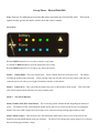
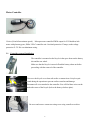
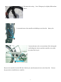
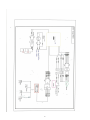
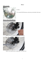
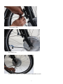
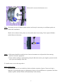
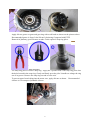
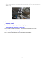
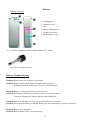
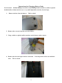
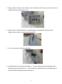
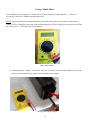
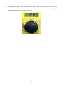
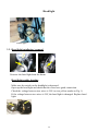
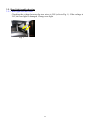
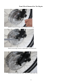
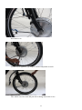
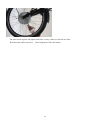
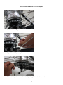
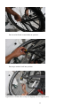
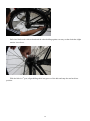
Hebb E-Bikes ElectroGlide 1000 Service Manual Table of Contents Set-Up Menu Motor Controller 1 2-3 Electrical Schematic 4 Motor 10 Battery 11-12 Replacing Battery End 13-15 Using a Multi-Meter 16-18 Charger 19 Head Light 20 Rear Light 21-22 Front Wheel Removal 23-26 Rear Wheel Removal 27-30 Set up Menu – ElectroGlide 1000 Note: There are five different power modes that can be used on the new ElectroGlide 1000. These mode options are only given to the dealer, and are not in the owner’s manual. Set-up Menu Hold the DOWN button for five seconds to enter the set-up menu. Use the UP or DOWN button to select the appropriate power mode. Hold the DOWN button for five seconds to save the mode selected. Mode 1: Pedelec/Ebike - This is the default mode. Power LED bar shows the assist power level. The throttle overrides the pedelec mode when used. Please note that if the user does not want to use the pedelec mode they can reduce the power to 0 with no power lights illuminated, and only use the throttle. Mode 2: Pedelec (EU) – This is the mode that reduces the power of the throttle to about 4 mph. This is the mode used in the European Union and many users may want this mode. Mode 3: Not used at this time. Mode 4: Pedelec EAF (Ezee Assist Factor) – This is basically pedelec with the throttle designating the amount of power. The throttle will not work without the pedals moving and you can set the amount of power by turning the throttle. The Power LED’s display the current (amps) level, with each dot representing approximately 4 amps. Mode 5: Ebike (Cruise) – The bike only works with the throttle (Ebike mode), and you can set the speed on the throttle by pressing the UP button (with your left hand). The Power LED’s display the current (amps) level, with each dot representing approximately 4 amps. 1 Motor Controller J Series (20 mile/hr maximum speed). Microprocessor controlled PWM output for 36V Brushless hub motor with planetary gears, Ebike / EPAC controller unit. Overload protection 25 amps, under-voltage protection 31.5V. Die cast aluminum casing. 2.1. Controller removal/installation The controller is mounted on the bicycle in the space between the battery slot and the rear wheel. Make sure that the bicycle is turned off and the battery taken out before proceeding with the removal of the controller. Turn over the bicycle on a clean soft surface or mount it on a bicycle repair stand during the operation to prevent surface scratches and damage. Disconnect all wires attached to the controller. You will find these wires on the underside center of the bicycle (below the battery slot base plate). Un-screw and remove connector casing cover using a small screwdriver. 2 Disconnect the wiring. Note: Wiring may be slightly different than shown. Loosen and remove the controller unit holding screws from the battery slot. 2 Loosen and remove the screws and nuts of the chain guard and dislodge the chain to push the controller out towards the right of the bicycle. 3 Remove the controller from the RH side of the bicycle, and disconnect the wire at the front fork. the procedure to install the new controller. 3 Reverse 4 Motor Motor overview EZ-DP-3 36V, nominal 500W planetary reduction gear brushless hub motor. Motor removal/installation Remove screws on torque plate using 4mm hex key. Remove nut using 19mm (or adjustable) wrench on axle. 5 Remove all the small parts, nuts, washers, torque plate, etc. Cut nylon ties with cutter or scissor. Un-screw and remove connector casing cover 6 Disconnect cable Disconnect wire Loosen nut on opposite side using a 19mm or adjustable wrench. 7 Release all 6 screws on hub motor cover. Note: Releasing screws will detune spoke tension, and it may be necessary to recalibrate spokes on wheel after installation. Knock axle as shown on the picture to release hub motor from casing. Tools required: Rubber mallet. Remove hub motor. Note: 1. Hub motor should be worked on in a clean environment to avoid particles from entering sensitive electronic equipment. 2. Ensure while working or when placing away the hub motor not to put weight or pressure on the axle to prevent damage of the axle. To install motor, reverse the steps above. Motor maintenance All motor parts are not serviceable by dealers with the exception of gears. Gears servicing is limited to re-greasing the gears or replacement of gears. Any modification or reparation work done without explicit consent of Hebb will immediately void warranty. 8 Apply silicone grease on gears and gear ring with a soft brush as shown on the pictures above. Recommended grease is Super Lube Silcone Lubricating Compound with PTFE. Removal of planetary gears: Remove washer. Tools required: Snap ring pliers. Use Snap ring pliers to remove snap ring – Apply the 2 pointed ends of the snap ring pliers into the holes located in the snap ring. Gently and firmly press the plier’s handles to enlarge the ring out of its groove. Remove the snap ring out and over the axle. To prevent water from leaking into the motor core, apply silicone as shown. Recommended silicone is GE waterproof paintable silicone. 9 Silicone should completely cover up the cable entry point in the axle. Refit motor wheel when the silicone is dry. 3.1. Motor trouble shooting Motor is not working Ensure that all cables are properly attached (see wiring diagram). Motor runs but cuts immediately or during riding. Check wires and ensure that all are in order. Open up motor to inspect for short circuitry. Motor makes grinding noises throughout ride. Open up motor to examine planetary gears for any damage or misalignment. 10 Battery Battery overview 1 3 2 4 5 1. Charging port 2. Housing screws 3. Fuse 4. Battery sliding groove 5. Locking pin socket 6. Bottom plate screws 6 Li+ / Lithium Manganese Oxide (LiMnO) Battery 37V 14AH 30A/250V Fuse and fuse cover Battery Trouble Shooting Problem: Battery does not fit properly into holder. Solution: Remove battery and realign it along the battery grooves. If fitting is too tight, apply grease on grooves for lubrication. Problem: Battery is in holder but the key does not turn. Solution: Push battery firmly down and ensure that it is securely in place. Check the alignment of battery locking socket and the pin. Problem: Battery is in holder, key is at “on” position but there is no power. Solution: Ensure that the battery is charged, battery pins are not damaged, and fuse is not blown. Problem: Battery pin is damaged. Solution: Replace Battery End – See instructions. 11 Problem: Battery cannot be charged. Solution: Be sure the charger is OFF when first connected to the battery, then turn ON. Be sure that the wall cord is firmly attached to the charger. Check the fuse on the charger. Check the input voltage on the battery. If zero, the internal fuse needs to be replaced. Problem: Battery is not giving enough mileage / has lower capacity than specification. Solution: Be sure the battery has been properly charged several times as a lithium battery requires several charges before it reaches its full capacity. Check voltage after a charge. The voltage should be approximately 41.5. Ride the bike on pedal assist level 3 for 10 miles; record the voltage. Contact the factory or your dealer with this information. The battery may need to be returned to the factory for amperage testing. NOTE: Batteries should be stored in a cool dry place when not being used, and charged for an hour or so every month. This will extend the life of the battery and keep the battery from being fully discharged. Leaving the battery in a discharged state for long periods of time will cause permanent damage. 12 Instructions for Changing Battery Ends Tools Needed: Medium Phillips screwdriver, small Phillips head screwdriver, rubber or plastic headed mallet, 4.5mm nut driver (or a very small adjustable wrench), electrical tape 1. Remove the fuse from the battery. This is critical. 2. Remove three screws from the end of the battery. 3. Using a rubber or plastic mallet, tap down on the battery end to remove. 4. Remove the electrical tape from the connection. Note the position of the red and black wires. This is critical. 13 5. Using a small screwdriver and a small wrench or nut driver (if necessary), disconnect the red and black wires from the battery end. 6. Connect the new end to the battery, noting the proper red and black wire placement. Tighten with screwdriver and wrench or nut driver. 7. Cover each connection with electrical tape. 8. Carefully slide the new end onto the battery. Note the position of the red and black wires making a loop (see picture below). After starting the end on the battery, the mallet may be needed to finish attaching the end to the battery. 14 9. Reattach the screws holding on the battery end. Re-insert fuse; tighten snugly. Test in a bicycle. 15 Using a Multi-Meter Every E Bike owner should have a multi-meter to check electrical voltage and fuses. These are inexpensive and can be found at any hardware store. NOTE: The multi-meter meter leads should be inserted into the multi-meter exactly as show below. Unless you are a qualified electrician and checking amperage, DO NOT plug the red (positive) lead into the 10A receiver. This may short out the battery. Basic Multi-Meter Checking Battery Voltage – Use the DC side (the V with the 3 dots and the straight line); put the meter on 200, and check the output voltage and the input voltage. Checking the output voltage 16 Checking the Input Voltage NOTE: If there is an output voltage reading, and the input voltage is zero, then the internal charging fuse is blown. This fuse can be replaced. Call the factory for details. Checking a fuse for resistance – Put the meter to 200 Ohms (see below). Zero out the meter by putting the red and black probes together – the meter should go to 0.4 or so. Put the probes on the fuse-ends, and the reading should be almost zero (or 0.4). 17 Checking AC voltage – This can be used to check the voltage coming out of the wall, or to check to see that the battery charger cord is working. See the meter on AC Volts (V with a squiggle), and insert the probes into the outlet or the cord. 18 Charger Charger Overview Lithium Ion battery charger 4 Amps, smart charge maximum charge time: 4 hours. Do not attempt to use Li+ charger with other battery types. Always ensure voltage is set correctly to your country’s specification. Charging protocol For optimum and safe charging, charge battery in a clean, cool and dry place. Ensure voltage on charger is set correctly and fuse is working and secure. Plug power cord into wall socket. Plug charger to battery and then turn on charger. Red light indicates charger is “on”. Yellow light indicates battery is charging. Green light indicates charging has stopped. Charger Trouble shooting Charger does not light up Ensure that voltage has been set correctly. Ensure that the 10A fuse has not blown, replace if necessary. Ensure that power cord is fitted in properly and in good condition. Charger yellow light is blinking The charger is sensitive to movement, temperature and voltage drop. Switch off charger and retry using the protocol described above. After retrying charging protocol, problem persists Test internal battery fuse. 19 Head light Head light 3.2. Head light installation / removal Unscrew the head light from the frame. Head light trouble shooting Make sure the switch on the headlight is depressed. Open up the head light and check that the wires have good connection. Check the voltage between two wires is 36V (as two yellow marks on Fig. 1). If the voltage between two wires is 36V, the head light is damaged. Replace head light. 20 Rear light Rear light 3.3. Rear light removal Unscrew the rear light from the frame. De-soldering the two wires. Tool: Soldering iron 3.4. Rear light installation Screw the rear light to the frame. Solder the two wires. Tool: Soldering iron Put the heat shrink tubes to cover two soldering points and shrink the tubes with a heat gun. Or carefully wrap with electrical tape. 21 3.5. Rear light trouble shooting 3.5.1. Rear light does not work. Checking the voltage between the two wires is 36V (refer to Fig. 1). If the voltage is 36V, the rear light is damaged. Change rear light. Fig. 1 22 Front Wheel Removal for Tire Repair Remove screws on torque plate using 4mm hex key. Remove nut using 19mm (or adjustable) wrench on axle. Remove all the small parts, nuts, washers, torque plate, etc. 23 Cut nylon ties with cutter or scissor. Un-screw and remove connector casing cover Disconnect cable 24 Disconnect wire Loosen nut on opposite side using a 19mm or adjustable wrench. Take wheel out of the fork and proceed to change inner tube or tire. 25 Put wheel back in place and tighten both sides evenly, a little on each side at a time. Reconnect the cables and wires. Check alignment of the disc brakes. 26 Rear Wheel Removal for Tire Repair Put the bike into 4th gear. Grip cable with fingers or pliers. Release shifting cable and nut from hub by pulling backward and outward. 27 Release nut and bolt assembly from brake assembly using 10mm wrench and nut driver. At this point, you should also remove the axle nuts and torque washer. Pull back and release chain from hub sprocket. Release rear wheel from frame to change tire or inner tube 28 Put rear wheel back on and chain on sprocket. Put torque washer back into position Tighten nuts of both sides evenly and slightly ( do not tighten yet ) 29 Pull wheel backward with one hand and the other holding against rear stay so that chain has slight tension is not loose. With the bike in 1st gear, align shifting cable into groove of the hub and snap the nut back into position. 30