1
PRINTED IN USA
P/N 990-30204
COPYRIGHT 2012
BRODERSON MFG. CORP.
LENEXA, KANSAS 66215
OPERATION AND
MAINTENANCE MANUAL
IC-200-2H & 3H
OWNER:_______________________________________________________________________
_______________________________________________________________________
_______________________________________________________________________
SOLD AND SERVICED BY:________________________________________________________
________________________________________________________
________________________________________________________
MODEL NO.________________________ SERIAL NO._________________________________
BRODERSON MANUFACTURING CORP.
STATEMENT OF WARRANTY FOR MOBILE CRANES
Broderson Manufacturing Corp. ("BMC") w arrants its products to be free from defects in material or workmanship at the date of
shipment from BMC. This warranty shall be effective only when validated by the return to BMC of it’s standard form of W arranty
Validation Certificate, duly completed and signed by the original purchaser from BMC and any subsequent purchaser who buys a
BMC product as a new product, and then only as to defects reported to BMC in w riting within 1 year or 2000 hours, whichever
occurs first, from the date a product is placed in service, as evidenced by such warranty validation certificate. THIS WARRANTY
APPLIES TO ALL PARTS OF BMC'S PRODUCTS EXCEPT ENGINES, DRIVE TRAINS, HYDRAULIC SYSTEM
COMPONENTS, OR ACCESSORY EQUIPMENT, WITH RESPECT TO WHICH BMC MAKES NO WARRANTY OF
MERCHANTABILITY OR FITNESS FOR A PARTICULAR PURPOSE AND NO OTHER WARRANTY OF ANY KIND,
EXPRESS OR IMPLIED; the sole warranties, if any , with respect theret o being those made by the re spective manufacturers
thereof.
THE SOLE REMEDY FOR BREACH BY BMC OF THIS WARRANTY SHALL BE THE REPLACEMENT OF ANY PARTS OF
ITS PRODUCTS WHICH WERE DEFECTIVE AT THE DATE OF SHIPMENT OR, IF (AND ONLY IF) REPLACEMENT OF
DEFECTIVE PARTS IS IMPOSSIBLE OR IS DEEMED BY BMC TO BE IMPRACTICAL, REPLACEMENT OF THE ENTIRE
PRODUCT OR, AT BMC'S OPTION, REFUND OF THE PURCHASE PRICE. T he replacement remedies include labor in
connection with the removal of defective par ts and the installation of t heir replacements, as w ell as the cost of delivery and
transportation of defective products or parts and the replacements thereof. The sole purpose of these remedies is to provide the
purchaser with free replacement of defective parts or, in the limited circumstances specified, replacement of the entire product or
a refund of the purchase pr ice. These exclusive remedies shall not be deemed to have failed of their essential purpose so long
as BMC is willing and able to replace defecti ve parts or the entire product or to ref und the purchase price. The remedies herein
provided shall be available only if BMC is given reasonable access to the product, including all allegedly defective parts,
promptly after the defect is discovered. BMC shall have the right to return any allegedly defective parts to its plant or any other
location selected by it, for inspection and testing to determine w hether they were defective at t he date of shipment, prior to
replacement thereof.
The warranty herein made is extended only to the original purchaser from BMC and any subsequent purchaser who buys a BMC
product as a new product. WITHOUT LIMITING THE GENERALITY OF THE FOREGOING, BMC EXPRESSLY DISCLAIMS
THAT THE WARRANTY MADE HEREIN EXTENDS TO A PERSON WHO RENTS OR LEASES ANY BMC PRODUCT OR
WHO PURCHASES ANY BMC PRODUCT AS A USED PRODUCT. For purposes hereof, a BMC product shall conclusively be
deemed "used" after the expiration of tw elve (12) months from its placement in service, as evidenced by a duly completed and
signed warranty validation certificate actually received by Broderson, or after such earlier time as it has been operated for m ore
than one hundred (100) hours. BMC shall have no liability hereunder with respect to products which have been subjected to
misuse, negligence, accident or other exte rnal forces which may have caused or accentuated any apparent failure of such
products to conform to the warranty herein made.
BMC does not w arrant any of its pr oducts to meet any state, local or municipal law, ordinance, code, rule or regulation. T he
purchaser must assume the responsibility for maintaining and operating the products w hich are the subject of this warranty in
compliance with such of the foregoing as may be applicable, and BMC shall not be liable for the purc haser's failure to meet such
responsibility.
THE WARRANTY HEREIN MADE IS IN LIEU OF ANY OTHER WARRANTY, EXPRESS OR IMPLIED. BMC MAKES NO
WARRANTY OF MERCHANTABILITY OR FITNESS FOR A PARTICULAR PURPOSE, OR ANY OTHER EXPRESS OR
IMPLIED WARRANTY OF ANY KIND, TO ANY PURCHASER, LESSEE OR RENTER OF NEW OR USED BMC PRODUCTS
OR ANY OTHER PERSON WHATSOEVER. NO PERSON IS AUTHORIZED TO ACT ON BEHALF OF BMC IN MODIFYING
THE WARRANTY HEREIN MADE OR IN MAKING ANY ADDITIONAL OR OTHER WARRANTY.
IN NO EVENT SHALL BMC BE LIABLE FOR INCIDENTAL OR CONSEQUENTIAL DAMAGES OF ANY KIND
WHATSOEVER.
THIS EXCLUSION OF INCIDENT AL AND CONSEQUENTIAL DAMAGES IS INT ENDED TO BE
INDEPENDENT OF ALL OT HER PROVISIONS OF T HIS STATEMENT OF WARRANTY AND SHALL BE GIVEN FULL
EFFECT NOTWITHSTANDING THE UNENFORCEABILITY OR FAILURE OF T HE ESSENTIAL PURPOSE OF ANY OT HER
PROVISION OF THIS STATEMENT OF WARRANTY.
THE FOREGOING DISCLAIMERS OF WARRANT
IES AND DI SCLAIMER OF LIABILITY FOR INCIDENT AL OR
CONSEQUENTIAL DAMAGES SHALL BE EFFECT IVE REGARDLESS OF WHETHER THE EXPRESS WARRANTY
CONTAINED HEREIN BECOMES EFFECTIVE AS PROVIDED IN THE FIRST PARAGRAPH HEREOF.
Document Number: WI-SM-002 Rev A
Effective: August 1, 2009
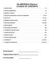
TABLE OF CONTENTS
SECTION 1 DESCRIPTION AND SPECIFICATIONS
Introduction…………………………………………………………………
IC-200-2H Dimensions…………………………………………………….
IC-200-3H Dimensions…………………………………………………….
Turning Dimensions……………………………………………………….
Description and Specifications…………………………………………….
1-1
1-2
1-3
1-4
1-5
SECTION 2 OPERATION
Safety Rules………………………………………………………………..
Crane Conditions………………………………………………
Lifting……………………………………………………………
Travel……………………………………………………………
Instruments and Controls…………………………………………………
Three Mode Steering..…….………………………………….
Control Functions………………………………………………
Sequence of Operation……………………………………………………
Driving the Vehicle……………………………………………..
Operating the Crane…………………………………………..
Normal Gauge Reading……………………………………….
Rated Capacity Limiter………………………………………..
Crane Capacity..…...……………………………………………………..
Crane Capacity Chart IC-200-2H…………………………….
Crane Capacity Chart IC-200-3H…………………………….
Capacity Example……………………………………………..
Sheave Block and Downhaul Weight…………………………………….
Two-Part Line Reaving…………………………………………………….
Four-Part Line Reaving……………………………………………………
Safety Devices……………………………………………………………..
Outrigger Check Valve………………………………………..
Boom Cylinder Holding Valve…………………………………
Hoist Brake and Holding Valve………………………………
Telescope Cylinder Holding Valve……………………………
Anti-Two-Block System………………………………………..
Optional Equipment………………………………………………………..
Installing Boom Extension……………...……………………..
Stowing Boom Extension……………….……………………..
Capacity Example for Boom Extension………………………
Front Auxiliary Winch…………………………………………..
Pintle Hooks..……...…………………………………………..
Switch and Indicator Symbols.……………………………………………
2-1
2-1
2-3
2-7
2-8
2-9
2-9
2-10
2-10
2-10
2-10
2-11
2-12
2-14
2-15
2-16
2-17
2-18
2-18
2-19
2-19
2-19
2-19
2-19
2-19
2-20
2-20
2-20
2-22
2-23
2-24
2-25
TABLE OF CONTENTS (CONTINUED)
SECTION 3 MAINTENANCE
Safety Rules………………………………………………………………..
New Unit Inspection and Test…………………………………………….
Operator Inspection and Test…………………………………………….
Maintenance Checklist…………………………………………………….
Fluid Volume……………………………………………………………….
Lubrication………………………………………………………………….
Lubrication Chart………………………………………………
Lubrication Schedule…………………………………………..
Boom Chain Lubrication……………………………………….
Rotation System Lubrication…………………………………..
Transmission Fluids……………………………………………
Axle Lubrication…………………………………………………
Wire Rope Lubrication…………………………………………
Hoist Cable Installation and Inspection…………………………………..
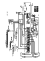
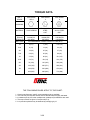
Hydraulic System Description…………………………………………….
Steering System………………………………………………..
JIC Schematic.…….………………………………………….
JIC Schematic Metric.…..…………………………………….
Hydraulic System Maintenance…………………………………………..
Care of Hydraulic Oil…………………………………………..
Hydraulic Oil Specification…………………………………….
Removal of Air from Hydraulic Circuits..…………………….
Hydraulic Seals…………………………………………………
Pressure Settings…………………………………………………………
Hoist Circuit…………………………………………………….
Boom and Outrigger Circuit…………………………………..
Boom Cylinder Holding Valve…………………………………
Telescopic Cylinder Holding Valves………………………….
Boom Chain Adjustment…………………………………………………..
Engine Maintenance……………………………………………………….
Air Cleaner Service……………………………….….……….
Cooling System…………………………………………………
Spare Parts Lists……………………………………………….
Major Engine Servicing or Overhaul………………………….
Mechanical Adjustments…………………………………………………..
Fasteners……………………………………………………….
Rotation Gearbox……………………………………………….
Axle Wheel Nuts………………………………………………..
Transmission and Axle Overhaul……………………………..
Park Brake Test and Adjustment……………………………..
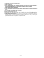
Torque Data…………………………………………………….
3-1
3-3
3-4
3-6
3-8
3-9
3-9
3-10
3-11
3-12
3-12
3-12
3-13
3-13
3-15
3-15
3-16
3-17
3-18
3-18
3-19
3-20
3-21
3-22
3-22
3-23
3-23
3-24
3-24
3-26
3-26
3-27
3-27
3-27
3-27
3-27
3-27
3-27
3-27
3-27
3-29
BRODERSON MANUFACTURING CORP.
IC-200-H INDUSTRIAL CRANE
INTRODUCTION
The Broderson IC-200-H was designed and built to provide safe, dependable and efficient crane
service. This we warrant by our testing and quality control procedures. To properly utilize the
full potential of the equipment, the following customer controlled conditions must exist:
1.
The operator must understand the equipment.
2.
The operator must know the operating characteristics.
3.
The operator must observe the safety rules.
4.
The equipment must be given proper maintenance.
This manual was written to provide information required for these conditions. T he
recommendations for periodic inspection, test and maintenance are minimum standards for safe
and economical performance.
When ordering parts: the unit serial number, unit model number, part number, part description
and quantity must be provided.
This unit must not be altered or modified without written factory approval.
To reorder this manual, ask for IC-200-H Operation and M aintenance Manual, Part Number990-30204. Contact your Broderson Service Representative at:
Broderson Manufacturing Corp.
P.O. Box 14770
Lenexa, Kansas 66285 USA
913-888-0606
NOTICE
If this crane becomes involved in an accident, please call Broderson Manufacturing Corp. at
913-888-0606, and ask for the Legal Department or the Service Manager. Also, please notify
your Broderson dealer.
1-1
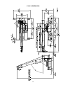
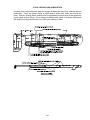
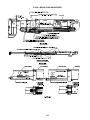
IC-200-2H DIMENSIONS
1-2
IC-200-3H DIMENSIONS
1-3
IC-200-H TURNING DIMENSIONS
1-4
SECTION 1
DESCRIPTION AND SPECIFICATIONS
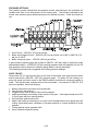
The IC-200-H is a self-propelled Industrial Crane designed for material handling and
installation, maintenance and repair of equipment, with special f eatures of self-loading
cargo decks, 4-wheel steer, and f ront-wheel drive (4-wheel drive optional). T he basic
unit consists of a chassis and hy draulic boom assembly. The chassis includes a f rame,
four hydraulic independently controlled outriggers, engine, torque converter, powershift
4-speed transmission, front planetary drive/steer axle and rear steer-only axle, fuel tank,
hydraulic tank, control station, power steering and dual pow er brakes. T he boom
assembly includes a hy draulic powered continuous rotation turret, 3 or 4-section
telescopic boom, hydraulic boom elevating cylinder, hydraulic boom telescope cylinders
and hydraulic powered hoist. A Rated Capacity Limiter is standard.
IC-200-2H:
3-section hydraulically extended boom with capacity of 30,000 pounds (13600 kg) at
a 6-foot (1.8 m) load radius. Horizontal reach of 36 feet (11.0 m) and vertical reach
of 45 feet (13.7 m).
IC-200-3H:
4-section proportional hydraulically extended boom with capacity of 30,000 pounds
(13600 kg) at a 6-foot (1.8 m) load radius. Horizontal reach of 50 feet (15.2 m) and
vertical reach of 58 feet (17.7 m).
General:
IC-200-3H
IC-200-2H
Weight:
Front Axle
Rear Axle
Total
13,960 pounds (6340 kg)
14,540 pounds (6600 kg)
28,500 pounds (12940 kg)
15,390 pounds (6,990 kg)
15,690 pounds (7,120 kg)
31,080 pounds(14,110 kg)
Length:
Overall
Chassis
22 feet 6 inches (6.86 m)
14 feet 11 inches (4.55 m)
22 feet 10 inches (6.96 m)
14 feet 11 inches (4.55 m)
Width:
7 feet 10.5 inches (2.40 m)
Height:
Overall
Deck
8 feet (2.45 m)
47 inches (1.19 m)
Wheelbase:
97 inches (2.46 m)
Ground Clearance:
11 inches (349 mm)
Angle of Approach:
24
1-5
degrees
General (Cont'd):
Angle of Departure:
24 degrees
Outriggers:
Spread
Penetration
11.8 feet (3.61 m)
3.5 inches (89 mm)
Turning Radius:
4-Wheel Steering
14.4 feet (4.42 m)
Aisle Width
for 90° Turn:
11.8 feet (3.61 m)
Steering Modes:
Rear Steer, Round Steer, Crab Steer
Road Speed:
18 MPH (29.0 km/h)
Gradeability (Calculated):
54 percent (28 degrees) 1
Grade Limit:
15 percent (9 degrees) 1
1) Calculated values based on GM 4.3L Gasoline Engine.
(Wheels may spin before these values are reached.)
Boom Movement:
Rotation
Elevation
Telescope
IC-200-2H
Continuous
0 to 73 degrees
21 feet (6.40 m)
IC-200-3H
Continuous
0 to 73 degrees
34.5 feet (10.52 m)
Boom Speeds:
Rotation
Elevation
Extension
1.7 RPM
20 seconds
33 seconds
1.7 RPM
20 seconds
50 seconds
Sheave Height (Nominal):
W/O Boom Extension
45 feet 4 inches (13.8 m)
With Boom Extension
59 feet 6 inches (18.10 m)
58 feet 8 inches (17.90 m)
73 feet 8 inches (22.40 m)
Horizontal Reach:
W/O Boom Extension
With Boom Extension
50 feet (15.2 m)
66 feet (20.1 m)
36 feet (11.0 m)
51 feet (15.5 m)
Engine:
Standard:
GM 4.3L V-6, EPA Tier 2 Woodward Dual Fuel:
GM Model 4.3L V-6 industrial gasoline engine with multiport electronic fuel
injection, dual fuel, catalytic converter, and engine management system. W ater
cooled, 262 CI (4.3L) displacement, 4-inch (102 mm) bore, 3.48-inch (88 mm)
stroke, 93 HP (69 kW) at governed speed of 2500 RPM. Maximum torque 206 ftlbs (279 Nm) at 1650 RPM . I ncludes special ex haust valves, seats and valve
rotators for use with LPG, 70-amp alternator, 30-gallon (113L) fuel tank and 43pound (19.5 kg) LPG tank. Hig h temperature and low oil pr essure shutdown is
included in engine management system. T hrottle control switch for setting
engine speed at 1200 or 1800 RPM.
1-6
Optional Engines and Engine Accessories:
Diesel Engine:
Cummins QSB3.3L Turbo, EPA Tier 4i:
Cummins QSB3.3 Tier 4 I nterim turbocharged diesel engine. Water cooled, 4cylinder, 199 CI D (3.3L), 3.74-inch (95 mm) bore, 4.53-inch (115 mm) stroke,
100 HP (75 kW) at governed speed of 2600 RPM. Maximum torque is 306 f t-lbs
(415 Nm) at 1600 RPM. 120-amp alternator included. 30-gallon (114 L) fuel tank
capacity. High temperature and low oil pr essure shutdown included in eng ine
management system. Throttle control switch for setting engine speed at 1200 or
1800 RPM. Diesel oxidation catalyst muffler; Air intake pre-cleaner; Charge air
cooler; 1500 watt, 120 vac, block heater; and grid heater included. Net Weight:
200 pounds (91 kg)
Spark Arrester Muffler:
Spark arrester muffler used in addition to standard muffler. Net Weight: 10
pounds (5 kg)
Engine Heater for Dual Fuel Engine Only:
Heater for engine. Engine coolant heater installed with hoses in coolant system
to circulate warm water through engine. Plug s into 120V AC ex tension cord.
1500 watts.
Transmission:
Standard 2-Wheel Drive:
Powershift transmission with four speeds in f orward and reverse. Provides
powershifts at any engine speed in any gear. All shif ting is done w ith a sing le
lever electrical control mounted on t he steering column. Multiple-disc clutch
packs operated by solenoid v alves provide reverse, neutral, forward and speed
selection. Equipped with oil cooler and filter.
Optional 4-Wheel Drive Transmission:
Same as 2WD transmission with an additional output shaft to drive the rear axle.
Electro-hydraulic control for shifting between 2WD and 4W D. T his option
includes the 4-wheel drive axle listed below.
Transmission gear ratios:
1st
2nd
3rd
4th
Forward and Reverse (2WD & 4WD)
5.72 to 1.0
3.23 to 1.0
1.77 to 1.0
1.00 to 1.0
Torque Converter:
Standard:
Stall torque ratio of 2.2:1, attached to engine flywheel.
1-7
Front Axle:
Standard:
Planetary drive/steer front axle with 15.78 to 1.0 ratio. Differential equipped with
"limited slip" feature. Driving effort is applied t o wheel that has traction. Front axle
mounted rigidly to frame.
Calculated Performance:
Drawbar Pull (pounds)
Travel Speeds (MPH)
Gear
1st
17,000*
3
2nd
8,900*
5
3rd
5,100*
10
4th
2,700*
18
*Calculated for GM 4.3L engine. W heels will spin in 1st or 2nd gear before these
values are reached with 2-wheel drive.
Rear Axle:
Standard 2-Wheel Drive:
Steering axle with 1½ degree oscillation in either direction.
Optional 4-Wheel Drive:
Planetary drive/steer axle with 24.98 to 1.0 ratio. Differential is not “limited slip” in
rear axle. 1½ degree oscillation in either direction. (Axle ratio compatible with 4WD
transmission output for front axle match.) Net Weight: 160 pounds (73 kg)
Steering:
Standard:
Hydraulic steering unit with two, 3-inch (7.6 cm) cylinders attached to each ax le.
Allows limited steering when engine is not running. Rear axle is the primary steer.
An electric switch in the operator’s compartment is used t o select rear-wheel
steering, four-wheel round steering or crab steering. Electronic sensors and control
box automatically align the steering when a new mode is selected.
Brakes:
Standard:
Split-system, four-wheel hydraulically-boosted multiple-plate wet disc brakes. Uses
mineral oil. Hand lever actuated disc-type parking brake on transmission.
Tires:
Standard 2-Wheel & 4-Wheel Drive:
15x22.5, 16-ply rating.
Tire Options:
Non-Marking Pnuematic:
385/65D22.5 16-ply rating Net Weight: 20 pounds (9 kg)
Foam Filling of Tires:
Foam filling of four IC-200 tires. Net Weight: 2000 pounds (907 kg)
Spare Tire and Wheel Mounted Standard Tire:
Extra wheel with standard tire (15X22.5, 16-ply) mounted, ready for service. Net
Weight: 350 pounds (159 kg)
1-8
Spare Tire and Wheel Mounted, Non-Marking Pnuematic:
Extra wheel with Non-Marking tire (385/65D22.5,16 ply) mounted, ready for
service. Net Weight: 350 pounds (159 kg)
Chassis:
Standard:
Cargo Deck:
Total Deck Area: 66 Sq uare Feet (6 m²). A m aximum of 17,000 pounds (7700
kg) may be carried on the deck at creep speed when centered over or between
axles. Seven stake pockets are provided along edges of deck for 1-inch (25
mm) pipe stakes. Stakes furnished. Cargo decks have skid resistant coating.
Lifting Rings:
Consists of four rings, one at each cor ner of the load deck , so sling can be
attached for lifting crane. Rings hang below deck surface when not in use.
Steps:
A step is located on each front corner providing access to deck area.
Outriggers:
Four hydraulic outriggers of box-beam construction. I ndependent control for
each outrigger. Hydraulic cylinders are equipped with direct-connected holding
valves. Pad dimensions: 11 inches (28 cm) x 16 inches (41 cm).
Pulling Eyes:
Two heavy eyes in front bumper provide for attachment of hook block so m ain
winch line can be used f or pulling loads at or near floor level. Also for anchoring
tag lines from load on hook.
Tie Downs:
Two holes in t he rear bumper (in conjunction with the pulling eyes) provide tie
down locations for transporting crane by truck or cargo container.
Accessory Storage Box:
Consists of front deck plate with removable and lock able cover, and box for
carrying sheave block and other items. Storage box is 14 inches ( 35 cm) deep x
10½ inches (26 cm) wide x 36½ inches (93 cm) long.
Headlight and Taillight Grilles:
Consists of welded steel protective grilles for headlights and t aillights. Easily
removable for replacing bulbs.
Chassis Options and Accessories:
Auxiliary Winch:
Optional worm gear winch, mounted behind front bumper, with a sing le lever
control at the operator's console. Hy draulic powered to provide bare drum line
pull of 10,000 pounds (4540 kg) at 33 feet per minute (10.2 m/min). Winch drum
is 3½ i nches (90 mm) i n diameter by 10 i nches (250 mm) l ong. This winch
includes 115 feet (35 m) of 7/16-inch (11.1 mm) wire rope, hook and 4-way roller
guide. T his rope can pull 5800 pounds ( 2630 kg) with a safety factor of 3.5:1.
Net Weight: 250 pounds (113 kg)
1-9
Pintle Hook - Rear:
T-60-AOL Holland pintle hook mounted on rear frame member, provides capacity
for 6000-pound (2700 kg) tongue weight and 30, 000-pound (13600 kg) trailer
weight. Net Weight: 15 pounds (7 kg)
Pintle Hook - Front:
T-60-AOL Holland pint le hook mounted on f ront frame member, provides same
capacity as rear pintle hook. Net Weight: 45 pounds (20 kg)
Rearview Mirrors:
One right-hand and one l eft-hand mirror, 6 inches (152 mm) w ide x 16 i nches
(406 mm) hi gh, mounted on deck stakes. Pi vot out of way when contacted by
obstacle at side of deck. Net Weight: 12 pounds (5 kg)
Operator Compartment:
Standard:
Operator control station provides one-position access t o all chassis and crane
functions. I ncludes adjustable operator's seat and retracting seat belt, fire
extinguisher, and bubble level.
Drum Rotation Indicator:
Provides tactile feedback to operator when hoist drum is rotating. Feedback
device attached to hoist control handle. Feedback is proportional to hoist speed.
Operator Compartment Options and Accessories:
Operator Guard: (Not Available with Cab)
Tubular steel weldment with heavy expanded steel mesh top section, bolts over
the operator's compartment. Operator Guard is not designed, rated or certified as
a Falling Objects Protection System (FOPS) or Rollover Protection System
(ROPS). Net Weight: 60 pounds (27 kg)
Operator Guard Door:
Hinged door covers operator compartment side opening . Has lat ch handle
outside and k nob inside. Rubber gasket contacts chassis. Net Weight: 40
pounds (18 kg)
All Weather Cab:
Consists of rigid mounted canopy section and removable hinged door with safety
glass. Rugged canopy structure with laminated glass front and t op. Door is
equipped with a keyed lock to protect operator's station. Includes defroster fan,
dome light, 12,400 BTU heater with 2-speed fan, and 12V elect ric windshield
wiper. T here are sliding windows in t he door and r ight-hand side. Net Weight:
220 pounds (98 kg)
Cab Heater Only:
Provides 12,400 BTU heater with 2-speed fan for units without All W eather Cab.
Net Weight: 12 pounds (5 kg)
Windshield Washer:
Provides reservoir, pump and nozzle for windshield washer.
Floor Mat:
Vinyl mat with foam backing covers floor, front wall, and lower portion of right
hand wall of operator’s compartment. Net Weight: 5 pounds (2 kg)
1-10
Suspension Seat:
Vinyl seat with a small suspension built in. Net Weight: 15 pounds (7 kg)
Deluxe Seat:
Deluxe seat with upholstery springs provides additional operator comfort. Net
Weight: 15 pounds (7 kg)
Noise Reduction Kit - Cab:
Includes vinyl floor mats and control valve cover and side panels of foam-backed,
perforated vinyl for noise reduction. Net Weight: 15 pounds (7 kg)
Air Conditioning:
Complete system using R134a coolant has combination cooling and heating unit
in cab. Net Weight: 125 pounds (57 kg)
Electrical System:
Standard 12 Volt DC:
Battery:
Gas Units:
Group 27 with 540 CCA rating.
Diesel Units: Group 31 with 950 CCA rating.
Lighting Group:
Consists of two 12V lamps, with high and low beams for driving; tail, brake and
turn signal lights and back up lights in r ear; front turn signals; and emergency
flasher switch at operator's station. 12V hor n actuated by button located on
shifting control.
Instrument Group:
Located at operator's station, includes fuel gauge and hourmeter, which records
hours only during actual engine operation. Also included are warning lights for
low oil and t ransmission pressure, check engine, high coolant and transmission
temperature, turn signals, high beams, hazard lights, parking brake and fourwheel drive.
Back-Up Alarm:
Provides pulsating sound from a 102 dB alar m when ignition is on and
transmission is in reverse. Conforms to SAE J994B.
Outrigger Alarm System:
102 dB alar m with alternating two-tone sound is act uated by a switch when the
OUTRIGGER DOWN controls are operated.
Optional Electrical Accessories:
Strobe Lights:
Two yellow strobe lights, one on each side of turret weight box, for high visibility
all around crane. Flashes 60- 120 times per minute. Each st robe draws only
one-half amp. Includes operator controlled switch. Net Weight: 5 pounds (2 kg)
Rear Work Lights:
Two halogen flood lights mounted between the grille bars in t he rear bumper.
Includes switch at operator station. Net Weight: 10 pounds (5 kg)
1-11
Boom Work Lights:
Two halogen work lights, one on left side of boom to light boom tip, and one on
right side of the turret to light ground under boom tip. Includes switch at
operator's station. Net Weight: 10 pounds (5 kg)
Hydraulic System:
Standard:
Tandem pump, direct-driven by engine, delivers 29 GPM (110 L/min) at 2600 PSI
(179 bar) and 34 GPM (129 L/min) at 2500 PSI (172 bar) at 2500 RPM governed
engine speed. System protected by relief valves, suction line st rainer and 10micron return line filter. 54-gallon (204 L) reservoir equipped with breather and
locking filler cap. (Maximum pressure on IC-200-3G is 3000 PSI on the 29 GPM
(204 L) section of the pump.)
Boom Assembly:
Standard:
Three or four-section, high strength steel construction, equipped with bearing
pads for efficient support and ex tension. Double- acting hydraulic cylinder
telescopes booms. The telescope cylinder and the double-acting boom elevation
cylinder are equipped with direct-connected holding valves. The four sections on
the 3H telescope proportionally. Boom angle indicator is on side of boom.
Boom Swing:
Standard:
Heavy-duty bearing swing gear with external teeth supports boom. Rot ation is
powered by hydraulic motor and w orm gear drive. Sw ing gearbox may be
adjusted as w ear occurs to minimize backlash. Boom is at tached by high
strength steel weldment.
Boom Hoist:
Standard:
Turret-mounted planetary gear hoist is hydraulically powered to provide a bar edrum line pull of 10,000 pounds (4536 kg) at a speed of 100-feet-per-minute (30
m/min). Hoist drum is 9 7/8-inch (251 mm) diameter by 16½ inches ( 419 mm)
long. The hoist includes 240 feet (73 m) of wire rope for 2H and 291 f eet (89 m)
of wire rope for 3H. W ire rope is ½-inch (13 mm) diameter. 125-pound (57 kg)
downhaul weight and swivel hook are included.
Boom Attachments:
Standard:
Anti-Two-Block Device:
Prevents damage to hoist rope and/or machine components from accidentally
pulling sheave block or downhaul weight against boom tip. Consists of trip arm
at boom tip, which is moved upward by sheave block or downhaul weight as hook
approaches boom tip. Trip arm actuates electric switch that is connected through
cable reel mounted on boom to solenoid dump valve in the hydraulic circuit. This
valve will dump the HOIST RAISE, TELESCOPE EXTEND, BOOM LOWER,
SWING LEFT and SWING RIGHT circuits. No other circuits are affected. These
circuits are returned to normal operation by operating the HOIST LOWER,
BOOM RAISE or TELESCOPE RETRACT control. T here is also an ov erride
keyswitch under the dashboard.
1-12
Rated Capacity Limiter:
Operational aid t hat warns operator of impending overload with audible and
visual signals. Has r ead-outs for load, boom angle, boom length and load
radius. In the event of an overload, dumps the following boom functions: HOIST
RAISE, TELESCOPE EXTEND, BOOM LOWER, SWING LEFT and SW ING
RIGHT. These circuits are returned to normal by lowering load to a safe resting
place with hoist or by retracting or raising boom to a shorter load radius. There
is also an override switch under the dashboard.
Four-Part-Line Sheave Block:
Double sheave block for 4-part-line requirements. 10- inch (254 mm) O.D.
sheaves for ½-inch (13 mm) diameter wire rope. Swivel hook with safety latch.
200-pound (95 kg) weight provides positive overhaul. I ncludes bar on top to
actuate trip arm of Anti-Two-Block device.
Optional Boom Attachments:
Boom Extension - 15 Feet (4.6 m), 2H:
Provides 15 feet (4.6 m) of additional length for lifting loads with load line. Boom
extension may be st owed alongside base boom section when not in use. Tip
sheave, attaching brackets and pins included. Deduct 400 pounds (180 kg) from
Capacity Chart when boom extension is in the stowed position. Includes trip arm
for Anti-Two-Block device. Net Weight: 520 pounds (236 kg)
Boom Extension - 15 Feet (4.6 m) Offset, 2H:
Provides 15 feet (4.6 m) of additional length for lifting loads with load line. Boom
extension may be st owed alongside base boom section when not in use. Tip
sheave, attaching brackets and pins included. Deduct 400 pounds (180 kg) from
Capacity Chart when boom extension is in the stowed position. Includes trip arm
for Anti-Two-Block device. Boom extension will tilt through three positions, in
line, 15 degree offset and 30 degree offset. Net Weight: 670 pounds (304 kg)
Boom Extension - 16 Feet (5 m) Offset, 3H:
Provides 16 f eet (5 m) of additional length for lifting loads with load line. Boom
extension may be st owed alongside base boom section when not in use. Tip
sheave, attaching brackets and pins included. Deduct 400 pounds from Capacity
Chart when boom extension is in t he stowed position. Includes trip arm for AntiTwo-Block device. Boom extension will tilt through 3 positions, in line, 15 degree
offset and 30 degree offset. Net Weight: 550 pounds (249 kg)
Two-Part-Line Sheave Block:
Single sheave block for 2-part-line requirements. Block is specially designed to
reduce height, 23 inches (58 cm) from top to saddle of load hook. 10-inch (254
mm) O.D. sheave for 1/2-inch (13 mm) rope. Sw ivel hook with safety latch.
Includes bar on t op to actuate trip arm of Anti-Two-Block device. Net Weight:
124 pounds (56 kg) for 2H and 200 pounds (91 kg) for 3H
Searcher Hook: (Nose Mount)
5000 pound capacity hook bracket is attached to the front of the boom tip with 4
pins through the boom extension attachment lugs. A hook with latch is pinned to
the tip of the bracket. Net Weight: 65 pounds (29 kg)
*** Specifications subject to change without notice ***
1-13
OPERATION SECTION
SAFETY RULES
GENERAL:
1. Since the manufacturer has no dir ect control over machine application and operation,
conformance with good safety practice is t he responsibility of the user and his oper ating
personnel.
2.
3.
4. The operator shall be r esponsible for those operations under his dir ect control. W henever
there is any doubt as t o safety, the operator shall hav e the authority to stop and refuse to
handle loads until safety has been assured.
5. The operator shall not engage in any practice which will divert his at tention while actually
operating the crane.
6. Do not run the engine in an enclosed area or indoors without adequate ventilation.
7. Do not use ether for starting. Ether is hig hly flammable and can be ig nited by the intake
manifold heater grid, causing engine damage or operator injury.
8. This list of rules is only a supplem ent to all f ederal, state, and local saf ety rules that may
apply.
CRANE CONDITION:
1. Before beginning operation each day, thoroughly inspect the entire crane to be sure it is in
good operating condition.
2. Inspect load hoist rope and w edge socket daily. W e recommend rope inspection,
replacement and maintenance in accordance with ANSI B30.5, Sec. 5-2.4.
2-1
3. Keep operator's compartment and decks free of mud and grease.
4. If crane is equipped with a cab, keep all window glass clean. Keep gauges clean.
5. Tools, lubricants, or rags on the crane should be kept in a secured toolbox.
6.
7.
8. The Rated Capacity Limiter must be checked before each shift and after each setup for the
proper operating configuration on t he display. I t must be inspect ed before each shif t and
tested with a known load at least once a month as described in the RCL operation manual.
2-2
LIFTING:
1. Always refer to Crane Capacity Chart in operator's compartment before handling load. Do
not exceed load r atings. Under some conditions the standard capacity ratings cannot be
recommended and must be adjusted downward to compensate for special hazards, such
as weak supporting ground, wind, hazardous surroundings, operator inexperience, etc.
The weight of the load should always be known.
2. Be careful to prevent load swinging. A swinging load can cause instability or loss of control
of the load. Be aware that the Anti-Two-Block System and the Rated Capacity Limiter can
cause sudden stopping of boom movement, which can cause the load to swing. Swing the
boom slowly whenever these systems might stop the boom.
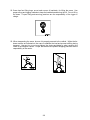
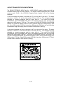
3. Do not allow anyone to put
any part of his body under a
load. The load may lower or
fall if there are damaged
parts in the crane. Also, the
load may drop a shor t
distance due to thermal
contraction of the hydraulic
oil in the cylinders.
4. Do not use crane to drag loads sideways. Do not use crane to raise grounded or fixed load by
using Boom Raise function.
5.
6.
7. Level the crane before lifting. A sm all incline will significantly reduce the capacity. Use
appropriate cribbing under the outriggers for leveling. All out riggers must be fully extended
and tires must clear the ground to use the ON OUTRIGGERS ratings.
8. Always use outriggers if possible. If you must lift on rubber, keep the load as close t o the
ground as possible to prevent tipover. M ove the load v ery slowly and use t ag lines t o
prevent load swinging.
2-3
9. Crane may tip at less than rated loads if the surface is uncompacted or wet dirt, or soft soil
with frozen crust, thin or cracked pavement, or surface near a hole or ledge. Always use
adequate outrigger floats and/or cribbing. See page 2-14.
10.The operator shall not leave the controls while the load is suspended.
11. Always use adequate parts of load hoist line for lifting heavy loads.
12. Always be sure the rope is properly seated and wound evenly on hoist drum.
13. Keep hands away from load hoist rope when hoist is being operated.
14. Be sure at least three wraps of rope are left on the hoist drum to ensure against rope pulling
out of its anchor.
15. Never wrap the hoist rope around a load. Always use approved rigging.
16. Avoid pinch points such as bet ween a r otating turret and t he cab, or in access holes of a
telescoping boom, or between the two-block mechanism.
2-4
CAUTION
Keep hands out of Anti-Two-Block mechanism. Serious injury can result from moving
parts.
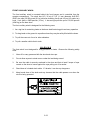
17. Avoid two-blocking.
A. Stop raising hoist line before downhaul or hook block strikes boom tip plates.
B. Pay out hoist line while extending boom.
C. Maintain clearance between downhaul weight or hook block and boom tip
while booming down.
DANGER
Two-blocking will abruptly stop boom lowering and boom swing as well as hoist
and extend. If the boom is moving fast, this will cause the load to bounce or
swing, which could cause loss of control of load or tipping.
18.The amount of counterweight supplied w ith this crane should nev er be chang ed.
Unauthorized addition of counterweight in the field to increase lifting ability constitutes a
safety hazard.
19. Always keep crane boom at least 10 f eet (3 m) away from electric power lines. (See
chart on side of turntable for boom clearance).
20. If boom should accident ally contact a pow er line, keep ground personnel away from
crane. Stay in the crane until the power source is de-energized. Move the crane away
from electrical hazard if this does not cause new hazards. If it is absolutely necessary to
leave the crane, jump clear of the crane with both feet together. Hop away from the
crane with feet together. The ground surface may be energized.
21. Do not operate outside during thunderstorms. Av oid all lig htning strike opportunities.
Consult local weather reports during inclement weather conditions.
2-5
22. Crane has f our lifting rings, one at each cor ner of load deck , for lifting the crane. Use
proper slings and rigging methods to keep the load balanced during the lift. Do not lift by
the boom. Pr oper lifting and secur ing practices are the responsibility of the rigger in
charge.
23. When transporting the crane, be sure it is properly secured to the vehicle. Utilize the tiedown anchors as indicated on the crane to stabilize the load and pr event shifting during
transport. Use caut ion to not over-tighten the chains and binder s when securing the
crane to the transport vehicle. Proper securement and prudent shipping practices are the
responsibility of the carrier.
2-6
TRAVEL:
1. For Pick and Car ry operation: T raveling with suspended loads inv olves so m any
variables, such as g round conditions, boom length and v ehicle acceleration, that it is
impossible to devise a single standard rating procedure with any assurance of safety. For
such operations, the user must evaluate prevailing conditions and det ermine safe
practices using precautions, such as the following:
A.
B.
C.
D.
E.
F.
G.
H.
I.
J.
K.
The boom shall be centered over front axle.
Use shortest boom practical.
Carry load as close to ground as practical.
Reduce travel speed to suit conditions (2 MPH (3 km/h) maximum).
Maintain specified tire pressures and lug nut torques.
Avoid sudden starts and stops.
Provide tag or restraint lines to snub swinging of the load.
Hand-held tag lines should be nonconductive.
Do not carry heavy boom loads and deck loads at the same time.
Do not pick and carry with boom extension installed.
Do not exceed the OVER FRONT, ON RUBBER capacity.
2. When raising the boom or moving the unit with boom elevated, be sure there is adequate
overhead clearance for boom.
3. For carrying loads on decks:
A. Boom must be retracted, centered and lowered as close as possible.
B. 2 MPH (3km/h) maximum road speed. Reduce speed below 2 M PH (3km/h) to
properly match condition of road surface and deck load stability.
C. Remove load hook from load before traveling.
4. Cranes with rear steering require close watch because of "tail swing" when the chassis is
turned in tight quarters.
5.
6. Every effort has been m ade to make the BMC Industrial Crane a stable vehicle.
However, with the rigid front axle and the unsprung oscillating rear axle suspension, the
operator must take care to control the vehicle speed to be compatible with conditions of
rough roads or uneven terrain.
7. When this crane is t o be par ked on a g rade, set parking brake and block wheels or
extend outriggers fully.
8. Shut off engine before refueling, and remove fuel cap slowly. Vapor pressure in tank can
cause a burst of fuel and vapor when the cap is r emoved. Aways refuel with proper fuel
and into proper tank.
9. Know your visibility limitations. Loads being carried on the deck or hanging on the hook
can add further limitations to visibility during travel. Always use a sig nal person when in
doubt.
2-7
INSTRUMENTS AND CONTROLS
The IC-200 instrument panel is eq uipped with a f uel gauge, an hour meter and a bubble
level. Also included are warning lights for low oil and t ransmission pressure, check engine,
high coolant and t ransmission temperature, turn signal, high beam, hazard lights, parking
brake and optional four-wheel drive.
The ignition switch is k ey operated and has O FF, RUN and ST ART positions. The ignition
switch should always be turned off and the key removed when the vehicle is left unattended.
A horn button is on the shifting control.
The BMC IC-200 is equipped with a standard lighting package. An on- off switch and a high
beam indicator are on the instrument panel. The dimmer switch is located on the left hand
steering column control. St op lights are controlled by operating the foot brakes. The turn
signal control is locat ed on t he left side of the steering column. M oving the lever down
indicates a left turn; up indicates a right turn. The emergency flasher lights are actuated by
a toggle switch on the instrument panel near the turn signal lever.
The hand br ake lever is locat ed on t he right side of the operator's seat. To apply, lift the
lever until the over-center position is reached. When adjustment is required, turn the knurled
knob on t he end of the lever clockwise to tighten. T he brake must be released before
adjustment can be made. A warning light shows when the hand brake is applied. The brake
and accelerator pedals are located and operated as t hey are in ot her vehicles already
familiar to the operator.
A lever on t he steering column controls the powershift transmission. M oving the lever
upward engages the transmission clutch for forward travel. Rotating the handle of the lever
selects the gear that is desir ed (first through fourth) and engages the clutch for that gear.
To put the transmission in reverse, the machine should be brought to a stop. The lever then
is pulled downward, through the neutral position, into reverse. T he transmission and dr ive
train components can be damaged by shifting from forward to reverse or vice versa while the
unit is in m otion, or while the engine speed is abov e 1000 RPM . A neut ral safety switch
prevents starting the engine with the transmission engaged. T he shift lever must be in
neutral to start the engine. A par king brake interlock switch prevents driving with the brake
on.
Normal engine speed control uses the foot accelerator pedal. A three position switch on the
right dash panel pr ovides preset engine speeds. Par king brake must be set to activate
system. Press the high idle control switch temporarily to the right, the engine will lock into
the preset levels. The center position of the switch enables t he engine to dwell at 1,800
RPM. The left switch position will lower the engine speed to 1,200 RPM. To restore the foot
accelerator, either temporarily release the parking brake fully or turn the engine off.
The optional four-wheel drive is controlled by a switch on the instrument panel. Select fourwheel drive when extra traction is needed. It is recommended to operate in two-wheel drive
except when wheel slip is likely.
2-8
THREE MODE STEERING FUNCTIONS
The IC-200-G is equipped with three-mode steering: four-wheel round steering can be used
for making tight turns; two-wheel rear steering should be used for traveling long distances;
crab steering can be used for maneuvering in tight places. A sw itch on the dashboard sets
the mode. Electronic sensors and controls automatically align the wheels when a new mode
is selected, as the wheels are steered past the centered position. T he steering wheel is
directly mounted to the steering control unit of the all-hydraulic power steering system. The
steering system will provide limited steering even if the engine stops running.
The Rated Capacity Limiter display and input panel are mounted on the dashboard.
Instructions are in the RCL Operation Manual and additional information is in t he Operating
the Crane section, the Crane Capacity section and Maintenance Section of this manual.
CONTROL VALVE FUNCTIONS
The controls for operating the outriggers, boom rotation, boom elevation, boom extension
and hoist are located along the forward dashboard area. T he control handles ar e directly
connected to the 3-position hydraulic valves. T he placard located next to these handles
identifies the function and direction resulting from each handle movement.
1. Swing or Slewing: Pulling back on the lever will rotate the boom to the operator's left;
pushing forward will rotate it to the operator's right.
2. Telescope: Pulling back on the lever will retract the boom; pushing forward will extend
the boom. Retract at a low to medium engine speed only. Overspeed will heat
hydraulic fluid and will not increase retraction speed.
3. Boom or Derricking: Pulling back will raise the boom; pushing forward will lower it.
4. Outriggers: The four outrigger levers may be operated simultaneously or individually.
Special attention must be given to avoid hitting personnel or obstacles
5. Front Winch (Optional): Pulling back will pay winch line in; pushing forward will pay
winch line out.
6. Hoist: Pulling back on t he lever will raise the load line; pushing forward will lower the
load line.
All controls may be used for simultaneous operation to achieve combinations of movements.
Some controls must be used together. For instance, the boom telescope and t he hoist
controls must be used together to maintain clearance between boom and load line hook.
Avoid holding a control lever in the open position after the function has reached the end of its
travel. T his will impose unnecessary stresses on t he components and heat the hydraulic
system.
2-9
SEQUENCE OF OPERATION
DRIVING THE VEHICLE
The following procedure is recommended for driving the vehicle:
1. Perform the daily inspection and test. (See Page 3-4)
2. Apply park brake.
3. Place transmission control lever in neutral.
4.
Start engine and allow a warming period.
5. While warming the engine, set up the Rated Capacity Limiter configuration.
6. Stow boom over front.
7. Pull hoist line snug.
8. Retract outriggers.
9. Step on the brake pedal.
10. Release park brake lever.
11. Shift transmission to desired gear.
12. Place forward/reverse lever in desired position.
13. Release brake and press on accelerator pedal.
14. Slow down when making turns.
15. Set park brake and lower outriggers or chock wheels to park.
W A R N I N G
Engine exhaust contains carbon monoxide, a poisonous gas that is invisible and
odorless. Breathing engine exhaust fumes can cause death or serious illness.
Do not run the engine in enclosed areas without adequate ventilation.
OPERATING THE CRANE
The following procedure is recommended for placing the crane in operation:
1. Perform daily inspection and test. (See Page 3-4)
2. Apply park brake.
3. Place transmission control lever in neutral.
4. Start engine and allow a warming period at low RPM.
5. While warming the engine, set up the Rated Capacity Limiter configuration.
6. Move accelerator pedal to medium to full speed.
7. Set all out riggers fully down on f irm, level surface. Use timber or steel plate cribbing
under outrigger shoes as needed on sof t or uneven surfaces. Outriggers should remain
set during all crane operations except for pick and carry.
8. Meter the controls when beginning or ending movement. This prevents suddenly starting
or stopping, which causes unsaf e load sw inging and shock loads on the equipment.
The control should be slightly actuated to begin movement and then slowly increased to
desired speed. Metering can be improved by coordinating with the accelerator pedal.
9. You may use the throttle control switch to set the engine speed t o 1200 or 1800 RPM
when the park brake is on. Return to idle by releasing park brake momentarily.
10. Release accelerator during idle time and shut off engine, if practical.
NORMAL GAUGE READINGS
Level Indicator: Do not operate crane if it is not level.
Fuel: Do not allow fuel tank to become empty. The engine will be difficult to restart and may
require "bleeding" of diesel injectors. Keep f uel tank full when idle to prevent condensation
in tank.
2-10
WARNING
Vapors can be formed inside fuel tank and cause buildup of pressure that can result
in sudden expulsion of gasoline and gasoline vapors from the filler neck when the
fuel cap is removed from a hot tank. Remove cap slowly. Fuel spray may cause
injury.
RATED CAPACITY LIMITER (RCL)
A rated capacity limiter is installed on the crane to assist the operator in estimating loads and
measuring load r adii. Please r ead the RCL O peration Manual for complete instructions on
operation of the system. Following are some additional operating tips.
Always be aware that the RCL can stop boom movement at capacity load conditions and in
two-blocking conditions. Use good judgment in controlling the speed of boom movements to
prevent shock loads and swinging loads.
If the RCL system stops the crane movement there are various remedies that may be used
to restart operation. If the hook is two-blocked, it should be lowered using the hoist control,
if safe. T he boom raise and t elescope retract may also be used if this is saf er. I n some
unusual circumstances it may be necessary to swing the boom before lowering the load. If
you are sure this will not cause an overload, you can press and hold the CANCEL button on
the RCL control and swing the boom to a safer position.
If the load is the
safe place using
retract may also
paragraph. DO
overload.
maximum for the loadline or attachment, the load should be set down in a
the hoist lower control and t he load or attachment changed. Telescope
be used and sw ing may be used, if safe, as descr ibed in t he preceding
NOT USE T HE BOOM RAISE CONTROL as this may increase the
If the load is at the maximum allowable load radius, the boom can be raised or retracted to a
safe radius or the load may be lowered to a safe place using the hoist control. If the boom
extension is at its angle limit, the boom must be raised or the load hoisted down.
If the boom is fully lowered until it stops, (about 0°) the RCL will show an overload condition
because the boom lift pressure sensors cannot read a useful pressure in this condition. To
remedy this, raise the boom slightly. Or, if the boom is fully raised, (about 73°) the RCL may
show an overload condition because the trapped pressure in the boom lift cylinder is sensed
to be an overload. To correct this condition, the CANCEL button on the RCL control can be
pushed and held and the boom lowered just slightly. Then check for other conditions before
lowering further.
2-11
If there is a malfunction of the RCL or Anti-Two-Block system that causes loss of boom
movement and cannot be remedied by the procedures above, the override keyswitch under
the dashboard may be required to move the boom.
WARNING
We recommend the CANCEL button and emergency override switch be used with
discretion. Improper or careless use of this switch can cause damage to the crane
and endanger people and property. The operator who uses these overrides in an
emergency should use good judgment.
There is a light on the dashboard to warn that one or more outriggers is not fully extended
when using the ON OUTRIGGERS setup on t he RCL. C heck the l ight daily when the
outriggers are down and there is no load on t he hook by raising and lowering each outrigger
about three inches. The light should come on when an outrigger is up.
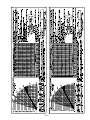
CRANE CAPACITY
Before lifting loads, the operator must read the Crane Capacity Chart and adher e to the
load capacities and radii of handling given. The information provided on this chart is based
on stability, structural strength and hydraulic capacity.
To operate the crane safely, the operator must know the weight of the load and handling
devices and t he radius of the lifting operation. T he crane must not be loaded bey ond the
specifications of the capacity chart except for test purposes as pr ovided in ASME B30.5
Section 5-2.2. The person responsible for the lift must be sure that the load does not exceed
the crane ratings at any radius at which the load may be during the entire lifting operation.
The weights of the hooks, blocks, downhaul weights, slings, and other handling devices must
be added with the load.
The Rated Capacity Limiter on t he crane is int ended to assist the operator in est imating
loads and measuring load radii and to alert the operator to impending overload conditions.
The use of the Rated Capacity Limiter does not replace the requirements of the preceding
paragraph. Ver ified weights and m easured radii must take precedence over the Rated
Capacity Limiter readings. Please read the RCL Operation Manual.
The Rated Capacity Limiter displays a load, load r adius and boom angle that are obtained
from electronic calculations using readings from pressure, length and angle sensors. These
readings cannot be exact and should be treated as est imates. I n general, the smaller the
load and the higher the boom angle, the larger the percent of error.
Be aware that the electronic and mechanical components cannot be 100% fail-safe. Do not
consider the system as a subst itute for good judgment, training, experience or accepted safe
operating practices. The operator is solely responsible for operation of the crane. Setting the
Rated Capacity Limiter for the configuration of the crane is necessary before starting a lift. If
incorrectly set, the system will not alert the operator to an impending overload, possibly
resulting in the loss of life or destruction of property.
If the Rated Capacity Limiter is inoperative or malfunctioning, repair or recalibration of the unit
must be done as soon as reasonably possible. The person responsible for lifts must establish
procedures for determining load w eights and r adii and conduct the lifts according to the
second paragraph above.
2-12
The Rated Capacity Limiter is desig ned to stop crane functions at the limitations of the
capacity chart. These are: BOOM LOWER, TELESCOPE EXTEND, HOIST RAISE, SWING
LEFT and SWING RIGHT. Great care must be exercised when handling a load near capacity
or near a two-blocking condition. If the boom is being lowered or swung, the load will tend to
swing if the Rated Capacity Limiter stops the boom movement. If the load is moving too fast,
the sudden st opping by the system can cause dang erous load swinging, which can cause
death or injury to personnel or property damage by impact with the load or by the crane
tipping.
WARNING
The Rated Capacity Limiter can suddenly stop the boom lower and swing functions,
causing the load to bounce or swing. Use great care when handing a load near
capacity limits or near a two-blocking condition.
CRANE CAPACITY CHART DEFINITIONS AND RULES:
The load radius is the horizontal distance from the centerline of boom rotation (the center of
the turntable when it is level), to the vertical load line with the load suspended. Because of
deflections of the boom and carrier, the load radius increases when a load is hoisted from its
resting place. The load radius may be measured with a measuring tape. If the desired load
radius falls between two load r adii on t he chart, it is r ecommended to use t he load r adius
with the lower capacity and not try to interpolate between the numbers.
Load capacity ratings on t his equipment are given on t he basis t hat operations are to be
conducted on firm and level terrain and in a saf e environment. T hese capacity ratings are
reduced in pr oportion to the deviation from the prescribed conditions. Any unfavorable
environmental condition, such as sof t, sloping or uneven terrain, high wind, or hazardous
surroundings constitutes a deviation.
The main boom capacities are given in direct relation to the radius at which the load is being
handled. Boom extension capacities depend on the boom angle as well as the load radius.
The capacities shown on t he capacity chart are the maximum allowable at the indicated
radius. The greatest load that may be handled by the BMC IC-200 is 30,000 pounds (13600
kg), but only at a 6 f oot (1.8 m) radius and on out riggers. All variances of loads and radii of
handling are shown on the crane capacity chart. A m etal chart is at tached near the
operator's seat and a laminated chart is included in t he literature compartment for the
express purpose of informing the operator when a load can or cannot be safely handled.
The capacities shown in t he 360° RO TATION columns of the capacity chart apply to the
entire 360 degree rotation of the boom and are maximum allowable at the indicated radius.
The capacities OVER FRONT are limited to the work area sectors on the placard.
Note that the 360° ROTATION capacities at some load r adii are much less t han the OVER
FRONT capacities. The least stable position of the boom is over the side of the crane. Use
great care when swinging a load f rom the front or rear of the crane toward the side of the
crane. The load must be known in order to assure that the crane will not tip.
2-13
2-14
2-15
CAUTION
A capacity load may be carried on the boom, or a capacity load may be carried on the
deck, but not at the same time. The total of the percent of deck load and the percent
of boom load must not exceed 100%. For example, if the boom load is 100% of its
capacity at its current load radius, the deck load capacity is 0%. If the boom load is
60% of the load rating for its load radius, the deck load capacity is 40% of maximum.
CAUTION
The ON OUTRIGGER capacities of this crane are based on all outriggers being FULLY
EXTENDED to a FIRM, LEVEL surface with no load on the tires. The crane may tip at
less than capacity loads if operated in the following manner:
A. Outriggers only partially extended and resting on curbing, shoring, etc. If the outriggers
are not all the way DOWN, they are not all the way OUT.
B. Crane operated on a hill or sloping surface. Cr ane will tip at less t han rated capacity
when load is lifted on downhill side.
C. Outriggers extended to a sur face that appears to be firm, but is unable to support the
outrigger pad at full rated loads. Examples of this type of surface are:
1.
Thin or cracked blacktop or concrete.
2.
Dirt that appears dry and firm on top but is moist or unpacked beneath the
surface.
3.
Dirt with a frozen but thin crust.
CAPACITY EXAMPLE (See Boom Extension Capacity Example Page 2-22)
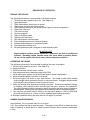
Refer to the IC-200-H capacity chart on the preceding page. A load 5’ X 5’ X 5’ (1.5 m x 1.5
m x 1.5 m) and weighing 14,000 pounds (6350 kg) is to be lifted onto the deck of the crane
for transport to a new location. We see on t he chart that 7500 pounds ( 3400 kg) is t he
maximum load on one-part line, so the sheave block is r equired. T he charts show the
weight of the standard sheave block to be 210 pounds ( 96 kg). The rigger says that two
slings are required, weighing a t otal of 50 pounds ( 23 kg).
The total load is
14,000+210+50=14,260 (6350 + 96 + 23 = 6469 kg).
Looking at the 360° ROTATION, ON RUBBER colum n we see t hat we can lif t 16,000
pounds (7250 kg) at a 6- foot (1.8 m)load radius. How ever, this radius is less than the
distance from the center of rotation to the center of the load, with the crane parked next to
the load, so the load cannot be lifted this way. This leaves the ON OUTRIGGERS columns.
The outriggers should always be used w henever possible anyway. W e see that we can lift
up to 18,500 pounds (8520 kg) at a 10-foot (3.0 m) load radius, either over the front or over
the side. If possible, position the crane to lift the load over the front. This is the best position
for stability. Checking the chart again, we see that the load is w ithin the deck load limit of
17,000 pounds ( 7700 kg) and t hat the travel speed w ith the load must be limited to creep
speed. Creep speed is less t han 2 MPH (3 km/h) and not to exceed 200 feet (60 m) in a 30
minute period. This is an approved relationship between load, tire pressure and speed.
CAUTION
REMEMBER THAT AS THE BOOM IS LOADED, DEFLECTION OF THE BOOM, TIRES,
ETC. WILL INCREASE THE LOAD RADIUS. SO BE CONSERVATIVE IN YOUR
CAPACITY ESTIMATE.
2-16
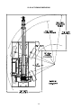
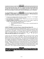
SHEAVE BLOCK AND DOWNHAUL WEIGHT
The capacity chart shows the approved hoist rope arrangements. The downhaul weight and
sheave blocks supplied by Broderson are specially designed to operate the Anti-Two-Block
system. O ther blocks or downhauls may bypass this system and create a dangerous
condition. Notice the load limit for each hoist rope arrangement.
The keeper pins that pass through the sheave plates must be locked in place with cotters to
hold the line on the sheaves. The load line must pass through the center of the downhaul,
through the wedge socket, and t he dead end clam ped in the block as shown in the figure
below.
When resting the downhaul or sheave block on the ground for changing it, use the following
procedure to prevent fouling the load line on t he hoist. Raise the boom about 5 feet (1.5 m)
and lower the hoist until the hook nearly touches the ground. T hen lay the hook on the
ground by lowering the boom, not the hoist.
2-17
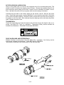
MULTI-PART LINE REEVING
For loads abov e 7500 pounds ( 3400 kg) the sheave block must be used. The 4-part-line
sheave block can be used for loads up to 30,000 pounds. T he optional 2-part-line sheave
block can be used for loads up t o 15,000 pounds. T he wedge socket should be pinned t o
the wedge socket anchor as shown in t he figure. T he dead end of the rope in the wedge
socket should be clam ped as shown in the figures. The clamp must not be used on the
live part of the rope. This will seriously weaken the rope. The sheave block should hang
straight, and the top of the block should meet the boom sheave plates squarely when pulled
up snugly.
2-18
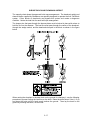
SAFETY DEVICES
There are certain safety devices on t he IC-200 that are designed to maintain control of a
load even if power or hydraulic line failure should occur. The operator should understand the
function and operation of these devices so that a continual check on their performance can
be made.
OUTRIGGER CYLINDER CHECK VALVE:
A double-acting check valve is int egrally mounted on each of the outrigger cylinders. T his
valve holds the outrigger in the extended position should pow er or hydraulic line f ailure
occur. This valve has no adjustment. If an out rigger creeps up w hile supporting a load,
there is an int ernal leak in the valve or in the outrigger cylinder piston seal. In either case,
maintenance is required.
BOOM ELEVATION CYLINDER HOLDING VALVE:
A single-acting holding valve is int egrally mounted on t he cylinder barrel. T his valve holds
the boom in the elevated position should power or hydraulic pressure line failure occur. This
valve is adjustable to hold the desired load. If the boom creeps down with loads up through
maximum capacity, this valve should be adjusted. If adjustment fails to correct the problem,
there is an int ernal leak in t he holding valve or the hydraulic cylinder. Refer to the
maintenance instructions.
HOIST BRAKE AND HOLDING VALVE:
The hoist has an automatic brake in the gearbox and a holding valve mounted directly on the
hoist motor to hold t he load. A clut ch in t he gearbox allows the winch to turn freely in t he
RAISE direction. T he brake is pilot released in t he LOWER direction and should allow
smooth stops of a load on the hoist.
BOOM TELESCOPE CYLINDER HOLDING VALVE:
A single-acting holding valve is flange-mounted to the cylinder rod end. This valve holds the
cylinder in the extended position should power or hydraulic pressure line failure occur. This
valve is adj ustable to hold t he desired load. I f the boom creeps in under load, this valve
should be adjusted. If adjustment fails to correct the problem, there is an internal leak in the
holding valve or the hydraulic cylinder. Refer to the maintenance instructions.
ANTI-TWO-BLOCK SYSTEM:
This system prevents damage to the hoist rope and machine components from accidentally
pulling the load hook against the boom tip. A pivot arm-actuated electric switch is connected
through a cable reel mounted on the boom to a solenoid dum p valve in the hydraulic circuit.
This valve will dump the HOIST RAISE, TELESCOPE EXTEND, BOOM LOWER, SWING
LEFT, and SW ING RIGHT circuits. No ot her circuits are affected. T hese circuits are
returned to normal operation by operating the HOIST LOWER or TELESCOPE RETRACT
control.An emergency override switch is pr ovided so t he boom can be operated in case of
system failure. This key-operated switch is located under the left side of the instrument
panel.
WARNING
We recommend the emergency override switch be used with discretion. Improper or
careless use of this switch can cause damage to the crane and endanger people and
property. The operator who uses this key in an emergency should use good
judgment.
WARNING
Do not bypass safety devices! Each device has a specific purpose and should not be
tampered with. Death, serious injury, or property damage could result from a safety
device that is not functioning.
2-19
OPTIONAL EQUIPMENT
NOTICE
Use appropriate ladders/steps to gain access to the boom tip and deck to perform this
installation.
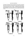
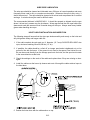
INSTALLING AND STOWING BOOM EXTENSION:
1.
Set the outriggers.
2.
Raise and extend the boom about 30 feet (9 m) above the ground, paying out load line
until hook is just above ground.
3.
Position boom over front, lower and retract boom, leaving the load line on the ground.
4.
If the sheave block is installed, remove it.
5.
Remove load line f rom tip sheaves and lay over side of boom opposite of the stowed
boom extension.
6.
Make sure the front stow pin is in place and t he attach pins are removed from the lugs
on the boom tip and the mating lugs on the boom extension.
7.
Remove the rear locking pin and swing the boom extension away from the rear end of
the boom until the attaching lugs mesh on the right-hand side of the boom.
8.
Insert the attach pins in the right-hand lugs and retain them with the hairpin cotters.
9.
Remove the front stow pin and sw ing the boom extension around to the front until the
left hand lugs mesh.
10. Insert the attach pins in t heir outer lugs and retain them with hairpin cotters. To insert
the fourth pin, it may be necessar y to rock boom extension side t o side, or up and
down.
11. Replace the rear stow pin and f ront stow pin in t heir brackets for storage and inser t
their hairpin cotters.
12. Lay the load line ov er the main boom and ex tension tip sheaves and insert the cable
retainer pins and cotters.
13. Install the downhaul weight, wedge socket and swivel hook on the load line if they are
not already installed.
14. Disconnect the anti-two-block wiring cable from the switch on t he main boom tip and
connect it to the cable connector on the boom extension base.
15. Check the Anti-Two-Block system for proper operation and Set Rated Capacity Limiter.
16. Stow the Boom Extension by performing steps 1-3 and by reversing steps 14-7, and
then follow steps 17-20.
2-20
17. Lay the load line back in the boom tip sheaves and insert both retainer pins & cotters.
18. Replace all of the pins in their lugs for storage and insert their haipin cotters.
19. Install the sheave block on the load line, if desired.
20. Check the Anti-Two-Block system for proper operation, and set Rated Capacity Limiter
configuration.
SETTING THE OFFSET ANGLE ON THE OFFSETTABLE BOOM EXTENSION:
1. The boom extension must be installed on the main boom tip and the load line, downhaul
weight and w edge socket installed on t he boom extension and secur ed with all of the
retainer pins.
2. Draw the load line taut with the hoist by pulling the downhaul weight against the bottom
of the tip sheave plates while holding the anti-two-block override switch under the
control panel.
WARNING
Be careful not to operate the TELESCOPE lever while overriding the
anti-two-block system. This may break the load line and allow the boom
extension and downhaul weight to fall, causing death or serious injury
to personnel.
3. Remove the offset index pin from the boom extension knuckle. To loosen the pin it may
be necessary to rock the boom extension tip up and down manually while maintaining the
proper tension in the load line.
4. Lower or raise the load line w ith the hoist until the 0, 15, or 30 degree offset holes align
in the knuckle.
5. Insert the index pin in the knuckle and retain it with the hairpin cotter.
6. Set Rated Capacity Limiter configuration.
STOWING THE BOOM EXTENSION:
1. If the boom extension is offset to 15 or 30 degrees, return it to the zero offset position as
described above.
2. Perform steps 16-20 of the boom extension installation and stowing procedure.
3. Set Rated Capacity Limiter configuration.
2-21
CAPACITY EXAMPLES FOR BOOM EXTENSION
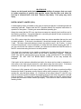
The BOOM EXTENSION ANGLE and the LOAD RADIUS capacit y charts must both be
considered when using the boom extension. The smaller capacity specified by the 2 charts
must be used. Ref er to the IC-200-3H, Capacity Chart on pag e 2-15 for the following
examples:
In this first example the boom is elev ated to 30° ov er the side of the crane. The boom
extension is offset to 15°, and the load radius is 32 f eet (10.0 m). T he outriggers are fully
extended on concrete pavement and t he crane is lev el. T he column for BOOM
EXTENSION, ON OUTRIGGERS 360° show s the capacity at the 32 foot (10.0 m) l oad
radius to be 4550 pounds ( 2010 kg). T he column for BOOM EXTENSION, MAIN BOOM
ANGLE 30° shows the capacity at the 15° boom extension angle to be 3000 pounds ( 1369
kg). Since 3000 pounds ( 1360 kg) is less t han 4550 pounds ( 2010 kg), the load ( including
the downhaul weight and slings) must be limited to 3000 pounds (1360 kg).
In the second example the boom is elevated to 40° over the side of the crane. The boom
extension is of fset to 0°, and t he load r adius is 38 f eet (12.0 m). T he outriggers are fully
extended on concrete pavement and t he crane is lev el. T he column for BOOM
EXTENSION, ON OUTRIGGERS 360° show s the capacity at the 38 foot (12.0 m) l oad
radius to be 3500 pounds ( 1500 kg). The column for BOOM EXTENSION - STRAIGHT OR
OFFSET, MAIN BOOM ANGLE 40° shows the capacity at the 0° boom extension angle to be
3900 pounds (1770 kg). Since 3500 pounds ( 1500 kg) is less t han 3900 pounds ( 1770 kg),
the load must be limited to 3500 pounds (1500 kg).
2-22
FRONT AUXILIARY WINCH:
The front auxiliary winch is m ounted behind t he front bumper and is controlled from the
operator compartment. T he winch has 115’ ( 35 m) of 7/16” (11 mm) diameter 6x36 EIPIWRC wire rope (20,200 pound (91 kn) minimum breaking force) and a 5-ton (4.5 metric ton)
hook. Lim it pulls t o 5000 pounds ( 22 kn). I t has a sing le-part-line pull of 10,000 pounds
(4540 kg) on the bare drum.
The front auxiliary winch is designed for the following uses:
1. As a tag line for restraining loads on the boom load line during pick-and-carry operation.
2. To drag loads on the ground to a position where they may be safely lifted with the boom.
3. To pull the crane out of mud or other obstacles.
4. To pull a smaller vehicle that is stuck.
WARNING
The front winch is not designed for lifting personnel or loads. Observe the following safety
rules:
1.
Never lift or carry personnel with the winch and wire rope.
2.
Do not allow anyone to stand near or under the load being moved.
3.
Be sure the cable is secur ely anchored in t he drum and t hat at least 5 wraps of rope
remain on the drum to insure against the rope pulling out of its anchor.
4.
Stand clear of a loaded winch cable. If it breaks, it can be very dangerous.
5.
Keep hands clear of the winch and any sheaves that the cable passes ov er when the
winch is being operated.
2-23
PINTLE HOOKS:
Available Pintle Hooks allow the crane to tow other disabled vehicles and trailors, and drag
loads.
1. Observe the capacity ratings marked near the hook when towing.
2. Exceeding the capacities can damage the drivetrain.
3. Use slow and smooth motions to avoid shock loads or overrunning loads. Make sure
other vehicle is occupied and controlling the vehicle being towed.
Pintle Hooks also allow the crane to be towed.
1. Use appropriately sized straps or chains.
2. Place transmission in Neutral. Utilize an Operator to activate brakes as needed and
steer the crane while being towed.
3. Do not exceed a towing speed of 5 mph (8 kph).
2-24
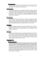
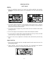
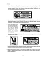
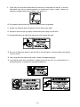
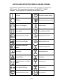
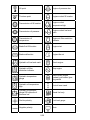
SWITCH AND INDICATOR SYMBOLS ON BMC CRANES
The following list shows the symbols used to label switches and indicators on
BMC cranes. Most symbols are derived from the ISO 3767-1:1998(E)
standard. Not all symbols will be included on your BMC crane.
On/Start
Windshield washer switch
Off/Stop
Windshield defroster switch
Battery not charging
Heater switch
Hour meter
Air conditioner switch
Read operator's manual
Ventilation fan switch
Sound level notification
Parking brake is set
Headlights (main/high
beam)
4-wheel (round) steer
Work light
Rear-wheel steer
Hazard lights
Crab steer
Rotating beacon or strobe
lights
2-wheel drive
Turn signals left/right
4-wheel drive
Windshield wiper switch
Tire pressure
2-25
Lift point
Engine oil pressure low
Tie-down point
Engine coolant fill location
Transmission oil fill location
Engine coolant
temperature high
Transmission oil pressure
Engine coolant low level
mark
Transmission oil
temperature
Engine air filter restriction
indicator
Brake fluid fill location
Engine start
Brake malfunction
Engine idle set
Hydraulic oil low-level mark
Check engine
Hydraulic oil filter
restriction indicator
Stop engine
Hydraulic temperature
gauge
Wait to start/ engine
preheat/ grid heater/ glow
plug switch
Hydraulic oil temperature
high
Control lever travel
Hydraulic oil pressure
gauge OR hydraulic oil
pressure low
Diesel fuel only
Positive polarity
Fuel level gauge
Negative polarity
Drain
2-26
MAINTENANCE
SAFETY RULES
1. Lower load and boom , shutdown engine, remove key and put it in a safe place. Place
warnings on the ignition switch and crane controls to prevent unauthorized starting or
movement during maintenance. Disconnect battery when disabling crane. Disconnect
battery, RCL and engine electronic module when welding on crane.
2. Relieve hydraulic pressure when working on hydraulic parts by cycling the controls with the
engine shut down.
3. Allow fluids and parts to cool before working on them.
4. Read maintenance instructions before beginning work.
5. Do not check for hydraulic leaks with hands. If a mist of hydraulic oil is noticed around a
line or component, use car dboard or other material to check for location of leaks. High
pressure fluid leaking from a small hole, can be almost invisible, yet have enough force to
penetrate the skin. If injured by escaping fluid, see a doct or at once. Serious reaction or
infection can occur.
6. Wear safety glasses and shoes.
7. Do not wear loose-fitting or torn clothing.
8. Remove rings and other jewelry.
9. Wear heavy leather gloves when working on wire rope.
10. Keep fingers, clothing and hair away from moving parts.
11. To prevent falls, clean areas of crane that are stepped on for access to crane parts. Wear
slip resistant footwear. Use appr opriate ladders/steps to gain access t o boom tip and
deck.
12. Avoid placing body parts in pinch points. Use t ools that extend through the pinch points
when possible. Block the moving parts securely when it is necessary to work in pinch
point areas.
13. When inflating or adding air to a t ire, place a t ire cage over the tire and use a clip-on
inflater chuck with an extension hose that will permit standing behind the tire tread when
inflating. Use proper tire handling equipment when changing any tires of this size.
14. Do not work on any machine that is supported only by jacks or a hoist. Always use adequate blocks or jack stands.
15. If it is necessary to work on the boom in an unst owed condition, block it to prevent it from
dropping unexpectedly.
3-1
16. Use a hoist when lifting components that weigh 50 pounds (22 kg) or more. Follow all
hoist and rigging safety rules.
17. Do not use lower grade fasteners if replacements are necessary.
18. When reinstalling wiring or plumbing after repairs, be sure that it will not be damaged by
rubbing against sharp, rough or hot surfaces or edges.
19. Never use a rope clip on liv e side of the load hoist rope. T his will seriously weaken the
rope. Death or serious injury can result from the misuse of a rope clip on the hoist rope.
20. Replace any instruction or warning placards that are lost or damaged or not readable.
21. Always replace all guards and covers after working on the crane.
22. After working on the hydraulic system, remove air from the lines and cylinders involved by
cycling them full stroke with the engine running until the functions operate smoothly.
23. When welding on the crane or on anything connected to the crane by wire rope or other
conducting link, disconnect the battery, the Rated Capacity Limiter display and computer
and the engine electronic control module. W hen welding on the boom or turntable assembly, remove the cable reel and any other electronic components bolted to these assemblies.
24. When using pressure spray to clean the crane, cover all elect ronic components with
sheets of plastic to protect them from spray.
25. Do not allow antifreeze to contact skin. Rinse of f spills immediately with plenty of water.
Antifreeze is highly toxic if ingested.
26. Always disconnect negative cable f irst and r efasten last to prevent accidental short
through chassis components.
CAUTION
Even with low voltage electrical systems, severe arcing can occur. Electrical shock or
component damage can result from contact with energized conductors. Use caution
when working with any electrical device.
3-2
MAINTENANCE
The Broderson IC-200 Industrial Crane will perform better and longer if a program of inspection, lubrication, adjustment and general preventive maintenance is followed. We recommend
the following schedule:
NEW UNIT INSPECTION AND TEST
The following inspection and test should be made before placing the unit on the job. This will
insure that no damage or loss of operating capability occurred during shipment.
1. Check for physical damage.
2. Check for leaks at fittings and drips under chassis.
3. Check radiator coolant level.
4. Check engine oil level.
5. Check hydraulic oil reservoir level.
6. Check transmission oil level.
7. Check fuel tank level.
8. Check tire pressure.
9. Check for loose pins, bolts, and retainers.
10. Check for operation of foot brake.
11. Check for operation and adjustment of parking brake. (pg. 3-27)
12. Check for operation of accelerator pedal.
13. Start engine.
14. Check power steering for operation.
15. Check operation of transmission gear selector lever.
16. Check lights for operation.
17. Test-drive unit and check for normal operation.
18. Check operation of hydraulic outriggers.
19. Check boom rotation.
20. Check boom elevation.
21. Check boom extension (pay out hoist cable during power extension).
22. Check boom chains and chain sheaves on IC-200-3.
23. Perform cable break-in procedure as described on page 3-14.
24. Check anti-two-block system for proper operation and cutout of boom functions.
25. Perform a load test according to the Rated Capacity Limiter Operation Manual.
26. Check the outrigger warning light for proper operation as described on page 2-12.
WARNING
When the Rated Capacity Limiter is inoperative or malfunctioning, it must be repaired
as soon as reasonably possible. When a lift must be made without a properly functioning load indicator or RCL, the designated lift supervisor must establish procedures for
determining load weights and load radii and conducting the lift safely.
3-3
OPERATOR INSPECTION AND TEST
An operator, in the course of normal operation, should make certain observations, inspections
and tests to assure that the unit is ready to perform safely.
Daily:
1. Check levels of engine oil, coolant and transmission fluid.
2. Check air cleaner intake system for cracks or looseness.
3. Check general condition of tires.
4. Visually inspect for loose pins, bolts, physical damage and leaks.
5. Check hydraulic hoses, particularly those that flex during crane operation.
6. Check hydraulic oil level.
7. Check fuel level.
8. Check hydraulic filter indicator gauge after running at least twenty minutes.
9. Check hydraulic brake operation.
10. Check parking brake operation. (See park brake test and adjustment.)
11. Check power steering operation.
12. Observe chassis for normal driving operation.
13. Observe boom operation for normal power and speed.
14. Check load line and hooks for damage.
15. Check condition of sheaves and load line retainers.
16. Check anti-two-block system for proper operation.
17. Check back-up alarm for proper operation.
18. Check operation of all transmission gears, forward and reverse.
19. Clean all glass (if equipped) and check for cracks.
20. Check operation of all warning and safety devices.
21. Check operation of Rated Capacity Limiter according to the RCL Operation Manual.
22. Check the outrigger warning light for proper operation as described on page 2-12.
23. GM 4.3L Gas or Dual Fuel Engine, per engine manual:
a. Inspect foot pedal travel and operation
b. Verify “Check Engine” light illuminates with key on and engine off
c.
Inspect for exhaust leaks
24. Cummins QSB 3.3L Diesel Engine, per engine manual:
a. Check crankcase breather tube
b. Drain water from diesel fuel filter.
c.
Inspect cooling fan
d. Check dust ejection valve
e. Inspect drive belts
f.
Check air cleaner restriction indicator
WARNING
Vapor can form inside a fuel tank and cause a buildup of pressure. This can result in a
sudden expulsion of gasoline and vapor from the filler neck when the fuel cap is removed from a hot tank. Remove cap slowly. Fuel spray may cause injury.
3-4
OPERATOR INSPECTION AND TEST
Weekly:
1. Check tire pressure: 120 PSI (827 kPa).
2. Check for loose wheel nuts. (500 foot-pounds (680 N-m) torque required.)
3. Check lights and turn signals.
4. Check power steering lines for damage.
5. Check brake lines for damage.
6. Check operation of horn.
7. Check operation of hoist brake for smoothness.
8. Check outrigger holding valves for operation.
9. Check boom lift holding valve for operation.
10. Check rotation gears for looseness or backlash.
11. Check boom extension cylinder holding valve for operation.
12. Check operation of windshield wipers (if equipped).
13. Boom extension (if equipped) properly pinned with retainers in place.
14. On IC-200-3, check boom chains and chain sheaves.
3-5
IC-200 MAINTENANCE CHECKLIST
Refer to the component maintenance section of this manual and to the engine operator's
manual for complete instructions.
50 HOUR INTERVAL:
1. 50 hour lubrication as shown on lube schedule.
2. Inspect wire rope thoroughly.
3. Inspect for physical damage and leaks.
4. Clean radiator fins and check coolant level.
5. Check tire pressure and condition. Inflate tires to 120 PSI (827 kPa).
6. Check fluid levels in engine, transmission, hydraulic tank, and brakes.
7. Clean air filter inlet screen and empty the precleaner dust cup.
8. Inspect air intake and exhaust systems for cracks, leaks and loose bolts.
9. Change engine oil and filter after first 50 hours. Replace at intervals specified by engine
manufacturer thereafter.
10. Check tension and condition of fan and alternator belts.
11. Check the hydraulic filter indicator with warm oil; change element if indicated.
12. Check rotation gear and pinion fit and gear train backlash.
13. Check rotation bearing and gearbox bolt tightness.
14. Check axle mounting bolts and pins.
15. Torque wheel mounting nuts. (500 foot-pounds (680 N-m) torque)
16. Check for loose pins or pin retainers.
17. Check steering lines for damage.
18. Inspect sheaves and hooks for damage or excessive wear.
19. Visually inspect welds on boom, turret and outriggers.
20. Perform a load test according to the Rated Capacity Limiter Operation Manual.
21. Check operation of outrigger warning light as described on page 2-12.
22. Clean the two steering alignment proximity sensors’ tips with a rag.
23. Check park brake cable adjustment as described on page 3-27.
24. Check horn, outrigger alarm, and backup alarm.
250 HOUR OR 3 MONTH INTERVAL:
1. 50 hour maintenance.
2. 50 and 250 hour lubrication.
3. Clean engine and battery.
4. Check engine mounts and radiator mounts.
5. Inspect all bolts on the machine for tightness.
6. Visually inspect all welds for cracks.
7. Check hydraulic fittings and centerpost for leaks.
8. Adjust and lubricate boom chains and chain sheaves.
9. Perform all maintenance required by engine manual.
500 HOUR OR 6 MONTH INTERVAL:
1. 250 hour maintenance.
2. 50, 250 and 500 hour lubrication.
3. Check antifreeze for protection level and cleanliness.
4. Change hydraulic filter element, if not changed in the last 250 hours and inspect oil from
element.
5. Change transmission filter element and inspect oil from element.
6. Check condition of all operational and warning placards.
7. Torque mounting bolts on rotation bearing and gearbox, winch and axles.
8. Inspect boom sections for signs of overload, excessive wear, or other damage.
9. Perform all maintenance required by engine manual.
3-6
1000 HOUR OR 12 MONTH INTERVAL:
1. 500 hour maintenance.
2. 50, 250, 1000 hour and 12 month lubrication.
3. Change hydraulic fluid and filter and clean breather and reservoir.
4. Change transmission fluid and filter and clean strainer.
5. Replace vapor block inside slip ring. See turret installation in parts manual.
6. Perform all maintenance required by engine manual.
7. Place vapor block inside slilp ring. See turret installation in parts manual.
24 MONTH INTERVAL:
1. 12 month maintenance.
2. Pressure test engine cooling system.
3. Flush cooling system.
4. Fill with new coolant and distilled water.
5. Perform all maintenance required by engine manual.
S/N:_______________ HOURS:________ DATE:________ BY:_____________________
COMMENTS & PARTS REQUIRED:___________________________________________
___________________________________________________________________________
___________________________________________________________________________
___________________________________________________________________________
___________________________________________________________________________
___________________________________________________________________________
___________________________________________________________________________
3-7
FLUID VOLUME
Hydraulic reservoir – 54 gallons (204 L)
Fuel tank – 30 gallons (113 L)
Planetary hoist – 2.5 quarts (2.4 L)
Front auxiliary winch – 2 pints (0.9 L)
4x2 & 4x4 Front axle – 5.98 gallons (22.6 L) housing, 39 gallons (1.5 L) each hub
4x4 Rear axle – 4.68 gallons housing (17.7 L), .44 gallons (1.7 L) each hub
4x2 Rear axle – 0 gallons housing, .44 gallons (1.7 L) each hub
Transmission – 17.5 quarts (16.6 L)
Engine cooling system (Gas) - 15 (14.2L) to 17 (16.1 L) quarts depending on engine and
heater.
Engine cooling system (Diesel) - 20 (18.9 L) to 24 (22.7 L) quarts depending on engine and
heater; fill to bottom of fill neck in surge tank.
3-8
IC-200 LUBRICATION CHART
3-9
IC-200 LUBRICATION SCHEDULE
ITEM
DESCRIPTION
LUBE
LUBRICATION INTERVALS
50
250
500
1000 MONTHS
HOUR HOUR HOUR HOUR
X
X
X
12
X
X
1
2
3
4
5
Accelerator Pedal
Anti-Two-Block Arm
Axle Differential
Axle Kingpins
Axle Pivot Pin
MPG
SIL
424
MPG
MPG
6
7
8
9
10
Axle Planetary Hubs
Boom Cylinder Pins
Boom Ext. Pins
Boom Hinge Pin
Boom Rub Pads
424
MPG
MPG
MPG
SIL
11
12
13
14
15
Boom Chain
Boom Chain Sheaves
Brake Lever, Parking
Brake Linkages
Brake Reservoirs
EO
MPG
SIL
SIL
DTE
X
X
X
16
17
18
19
Cab Hinges & Latches
Control Valve Links
Drive Shaft Joints
Engine Oil (Gas Engine)
SIL
SIL
MPG
EO
X
X
X
X
20
21
Hook Swivel & Pin
Hydraulic Oil
SIL
HO
X
X
22
23
24
25
26
Outrigger Legs
Pump Shaft
Rotation Bearing
Rotation Gearbox
Rotation Gear Teeth
MPG
MPG
MPG
WGO
OGG
X
X
X
27
28
29
30
31
Rotation Pinion Bearing
Sheave Block
Sheave Pins
Steering Cyl. Ends
Steering Link Ends
MPG
MPG
MPG
MPG
MPG
X
32
33
34
35
Transmission, 4-Speed
Winch(es)
Wire Rope
Wire Rope Retainers
TPF
MPL
2-X
SIL
X
X
X
X
X
X
1 Zerk, Diesel
2 Points - Oilcan
Check @50, Change @12 Mo.
4 Zerks
1 Zerk
Check @50, Change @12 Mo.
2 Zerks
Wipe on.
1 Zerk
Spray or Wipe
Spray or Wipe* IC-200-3
6 Zerks* IC-200-3
Check @50, Change When
Brakes are Serviced.
3 Zerks 2WD, 6 Zerks 4WD
3 Max. Check Daily, Change @50,
then at 250 or 3 Mo. Max.
X
X
X
X
X
12
X
NOTES
X
X
X
X
X
X
12 Max. Check Daily, Change @1000
Hours or 12 Mo. Max.
Wipe on Legs.
2 Zerks
1 Zerk*
Repack @ overhual
Brush On.*
1 Zerk*
3 Zerks
2 Zerks Std, 2 Optional.
8 Zerks
4 Zerks
12 Max. Check @250, Change @12 Mo.
12
Check @250, Change @12 Mo.
Spray, Brush or Soak.*
*See Procedures in Manual
LUBE SYMBOLS
TPF - ATF Type F
2-X - AMOVIS #2-x
424 - Mobil Fluid 424 or Equivalent
DTE - Mobil DTE 10, Excel 15 or Equivalent
- (Do Not Use Brake Fluid)
EO - Engine Oil - See Specs in Engine Manual
HO
MPG
MPL
OGG
OGG
WGO
3-10
- Hydraulic Fluid - See Specs in Hyd. Sec.
- Multi-Purpose Gun Grease
- Multi-Purpose Gear Lube, SAE 80W-90
- Open Gear Grease, Such as Mobilkote S
- Silicone Lube, Aerosol with Concentrating Tube
- Worm Gear Oil, Exxon Cylesstic TK460
IC-200-3 BOOM CHAIN LUBRICATION
Lubricate inner chains and chain sheav es through windows with boom fully extended and set
horizontally. T here are grease fittings on chain sheav e shafts both inside and outside the
boom. Reach in through boom windows with a long tipped oil can and spray chains generously and grease sheave fittings. Do not attempt to grease chain shafts or oil chains inside boom
with engine running as boom may move while your hands are inside.
3-11
ROTATION BEARING LUBRICATION:
There is one grease zerk in a hole on the right-hand side of the turntable base plat e. This
should be used t o lubricate the bearing every 50 hour s. Rot ate the turntable about 45 degrees and pump some grease into the zerk. Repeat until the turntable has rotated 2 revolutions. Use about 8 ounces (230 cc) of grease each time the bearing is lubricated.
Lubricate the gear teeth of the rotation bearing at the 50 hour interval. Rem ove the pinion
cover. Brush open gear grease, such as Mobilkote-S, on the teeth on each side of the pinion
at four places around the bearing. Rotate the boom several times and check the coverage of
the grease on all of the teeth. Also, lubricate the pinion bearings at the zerk below the pinion
teeth. Replace the pinion cover.
TRANSMISSION:
Check the transmission fluid with the dipstick and add f luid through the dipstick tube as r equired. Use M obil ATF Type F or equivalent. Transmission factory service manuals are
available from Broderson. Order BMC Part Number 990-00021.
DRIVE AXLES-HUBS AND DIFFERENTIALS:
Maintain lubricant to levels shown here with Mobil 424 or equivalent. Ax le factory service
manuals are available from Broderson. Order BMC Part No. 990-00020.
*No lubricant is required in the center section of the 2WD rear axle.
3-12
WIRE ROPE LUBRICATION
The wire rope should be cleaned and lubricated every 50 hours of normal operation and more
frequently when used in dir ty or corrosive environments. W henever the rope is dirty or dry, it
should be serviced. The rope should be cleaned w ith solvent and compressed air or solvent
and rags. A wire brush may be used for difficult areas.
The recommended lubricant is AMOVIS #2-X. It should be sprayed or dripped onto the rope
where it is bent as it passes over the tip sheave. Wrap rags around the wire rope behind the
sheave and swab the excess oil that is carried along on the rope. Always wear heavy leather
gloves when handling wire rope.
HOIST CABLE INSTALLATION AND INSPECTION
The following steps will assure that the wire rope winds smoothly and evenly on the hoist and
will yield greater safety and longer cable life:
1. If the cabl e needs to be repl aced use ½ diameter (12.7 mm) 6X 25-EIP-RRL-IWRC wire
rope, minimum breaking force 26,600 lbs (117 kn).
2. If possible, the cable should be r olled off a st orage spool and st raightened out on t he
ground in line with the boom. If the ground is not clean or the space is too limited, the cable can be wound directly from the storage spool onto the hoist, but the spool must rotate
in the same direction as the hoist.
3. Check the seizings on the ends of the cable and replace them if they are missing or damaged.
4. Install the cable over the boom tip sheave and route it through the cable retainer loops to
the hoist drum.
5. Position the hoist drum with the cable anchor on top.
3-13
6. Insert the cable through the anchor slot and wrap it around the anchor wedge. The end of
the cable should extend past the wedge by about one inch (24 mm).
7. Slide the cable and wedge into the drum socket and pull firmly on the free end of the cable
to set the wedge. Seat the wedge securely with a brass or rawhide mallet.
8. Slowly rotate the hoist while applying tension on t he cable in front of the boom. Wear
heavy leather gloves and wrap rags around the cable to wipe off any dirt from the cable.
Keep hands away from the sheaves and hoist drum while the cable is moving.
9. After two turns of the hoist drum, stop the hoist and push the cable into the drum groove if
it has come out.
10. Slowly rotate the drum until the first layer of cable is on the drum. If any gaps between the
rope appear, back up the hoist and rewind. There must be no gaps.
11. After the first layer is on the drum, the hoist may be turned a little faster until the remainder
of the cable is installed.
12. Leave about 30 feet (9 m) of cable on the ground to install the sheave block. See the Operation Section for instructions on reeving and wedge socket attachment.
13. Install the cable retainer pins and cotters in the tip sheave plates.
14. For the cable preloading, extend the outriggers and at tach a load of about 2000 pounds
(900 kg). Extend the boom fully. Position the load at a 10-foot (3 m) load radius over the
right-hand side of the crane. Hoist and lower the load three times and check winding of
the rope on the hoist.
15. Attach about 5000 pounds (2300 kg) and repeat. Be sur e that the cable winds evenly on
the hoist.
16. If the cable appears to twist too much, remove the sheave block and rewind the cable on
the drum as in Steps 7-11.
17. Never lift more than the rated load on t he Capacity Chart for the parts of line and t ype of
wire rope being used.
18. Lubricate the cable as r ecommended in t he "Wire Rope Lubr ication" section. Inspect,
maintain and replace the cable in accordance with ANSI B30.5-1982, Section 5-2.4.
3-14
HYDRAULIC SYSTEM
The IC-200 hydraulic system consists of 2 subsystems, driven by a double pump with a single
inlet port. The 29 GPM (110 L/min) vane pump supplies the hydrostatic steering function and
the boom and outrigger functions. The hoist and brake booster are powered by the 34 GPM
(129 L/min) vane pump.
The boom, outriggers, hoist and opt ional front winch are controlled by one v alve assembly.
The 29 GPM (110 L/min) pump flow enters the steering flow control valve first and then flows
into the left-hand section of the control valve assembly supplying the swing, telescope, boom
and outrigger sections. The flow from the 32 GPM (129 L/min) pump enters the brake booster
flow control valve first and all but 4 GPM (15 L/min) is directed to the inlet section to the left of
the hoist valve. Adjustment procedures for the crane hydraulic functions are given on page 321 through 3-23. The schematic of the hydraulic system is shown on the next page.
STEERING SYSTEM
The steering system is shown in the schematic on the next page. The IC-200 steering system
is a load-sensing, demand-type system that takes only as much flow as is needed when steering and directs the excess flow to the control valve for boom and outrigger functions. The priority flow-control valve is in the line between the 29 GPM (110 L/min) pump section and control valve.
Oil from the 29 GPM (110 L/min) section of the pump goes into the priority valve at port "P."
When no st eering is r equired, the entire flow goes through the priority valve and leaves
through port "EF" to the crane valve. The crane operating speed is not affected, since there is
no loss of volume passing through the priority valve.
When the steering wheel is turned, the load-sensing line signals the priority valve to divert the
required amount of oil to the steering control unit to meet the steering system requirements.
The excess oil, not required for steering, flows to the crane control valve as usual. Since the
amount of oil r equired for steering is usually a sm all portion of the pump output, the crane
control valve is always operational while the unit is being steered. Crane operation speed is
reduced such a slight amount it is usually not noticed.
The steering control unit is non-load reactive. This means that bumps, curbs, and obstacles
cannot change the steering angle and are not felt in the steering wheel. It also means that the
wheels do not recenter when the steering wheel is r eleased. T he steering wheel must be
turned back to center at the end of a turn. The steering system pressure was set at 1800 PSI
(124 bar) at the factory, and this should not need adjustment.
The three steering modes are selected by a switch on the dashboard, which activates the automatic alignment system. Electronic proximity sensors and logic controls delay the switching
of the steering mode until the wheels are centered. The proximity sensors should be cleaned
periodically with a rag to prevent dirt buildup from blocking their operation.
3-15
3-16
3-17
CARE OF HYDRAULIC OIL
The hydraulic system contains many highly pressurized, precision components. To protect
these, it is very important to keep the hydraulic oil clean, at proper temperature, within the oil
specification and to the proper fill level.
The IC-200 is equipped with a 100-mesh suction strainer, a breather filter, a 10-micron returnline filter and a 54-gallon (204 L) tank. The filter must be changed whenever the filter indicator gauge under the control panel points to the red sector at full engine speed or at 500 hours
or six months maximum. Note: T he oil should be warmed by at least 15 minutes of normal
operation to get a good reading. The indicator should be checked daily.
The filter is located to the rear of the front axle. Clean the filter and the surrounding parts with
pressure washer before changing, to prevent dirt from getting into the clean oil tube. To minimize oil loss, close the shutoff valves under the tank.
BE SURE SHUTOFF VALVES ARE FULLY OPENED BEFORE STARTING ENGINE.
Remove the filter element and catch the hydraulic oil in a clean container. Pour the remaining
oil out of the old element into the clean container and inspect the oil for water and excessive
contaminants. If water is found, the oil should be chang ed in the reservoir and purged out of
the cylinders. I f excessive particles are found, the source should be locat ed and f ixed, and
the oil should be purged.
Lubricate the new element seal and inst all the new element. Open the shutoff valves. Run
the engine and check for any leaking around the seal.
The hydraulic oil should be chang ed every 1000 hour s or once a y ear, whichever is sooner.
Wash the oil tank and filters before changing the oil. Retract the telescope, boom and outrigger cylinders. Leave the shutoff valves open and r emove the drain plug. Cat ch the oil and
dispose of it properly. Remove the breather from the top of the tank and clean t he element
with solvent and compressed air. Clean out the tank with solvent and compressed air.
The suction strainer is located under the hydraulic tank and has a r eusable element. To service, remove the four bolts holding the two parts of the housing together. Remove the element
from the housing by turning the element counter-clockwise. Wash the element in clean solvent and allow to dry. Reassemble the strainer.
Replace the filter as described previously and refill the tank with new hydraulic oil that meets
the specifications in the table below. Start the engine and run it at low idle for 15 minutes to
filter the new oil. Then cycle all of the hydraulic cylinders at low idle and low pressure. Add
hydraulic oil to the dipstick full mark, if necessary, with cylinders retracted.
3-18
HYDRAULIC OILS FOR IC-200
AMBIENT TEMP RANGE: -40° to 75°F
(-40° to 24°C)
-15° to 110°F
(-26° to 43°C)
50° to 130°F
(10° to 54°C)
POUR POINT:
-40°F MAX
(-40°C)
-15°F MAX
(-26°C)
0°F MAX
(-18°C)
VISCOSITY INDEX:
140 MIN
95 to 100
95 to 100
VISC. SSU @ 100°F (38°C): 200 MAX
230 MAX
340 MAX
SSU @ 210°F (100°C):
44 MIN
47 MIN
53 MIN
EXAMPLES:
MOBIL DTE-13
MOBIL UNIV.-ATF
TEXAMATIC TYPE F
TEXACO HD 46
MOBIL AW-46
MOBIL DTE-25
CONOCO SUPER 46
TEXACO HD 68
MOBIL AW-68
MOBIL DTE-26
CONOCO SUPER 68
OTHER REQUIREMENTS: M ust contain rust and ox idation inhibitor, and antifoam and
antiwear agents. Must pass Vickers Vane Pump Test.
The IC-200 is factory filled with hydraulic oil for the -15° to 110°F (-26° to 43°C) range. If significant portions of time are spent operating below 20°F (-7°C) or above 100°F (43°C), the oil
should be replaced with an extreme temperature oil.
The oils shown are compatible with and may be combined with SAE 10W or SAE 20W-20 motor oil if it is necessary to add oil bet ween changes and the recommended oils are not available. These motor oils are not suitable substitutes when changing hydraulic oil because t hey
lack certain additives that are needed for hydraulic system use.
CAUTION
Never add kerosene or other "thinners" to hydraulic oil. These fluids have low aniline
points and consequently will cause rapid deterioration of certain packings and seals in
the hydraulic system.
CAUTION
Serious damage to the pump will result if it is run with the shutoff valve closed or with
insufficient oil level in the reservoir.
Observe the operation of the machine. If the oil is too cold, the machine will be sluggish and
should be warmed up further to prevent damage before sustained hard work is attempted. If
the oil is too hot, leakage will increase, pump efficiency will go down, and moving parts will not
be properly lubricated. If operating temperature is excessive, rapid deterioration of the oil will
result and m oving parts and seals w ill wear more quickly. The cause of the excess heat
should be determined and corrected. A possible indicat ion of excessive oil temperature is a
control valve lever that becomes hard to operate or sticks instead of returning to neutral.
3-19
REMOVAL OF AIR FROM HYDRAULIC CIRCUITS
To remove air from hydraulic circuits, perform the following steps:
1. Ensure all main shutoff valves on the reservoir are open.
2. Start the engine.
3. Raise and low er the boom minimum five times. Ensure that the cylinder travels full
stroke.
4. With the boom retracted and elevated to at least 65°, raise and lower the hook at least
once.
5. Extend and retract the boom minimum five times.
6. Swing the turret left one full revolution. Swing the turret right one full revolution.
7. Extend and retract each outrigger minimum five times. Outriggers can be operated in
pairs.
8. With the crane on outriggers, steer the crane wheels fully left and right three times in
each steering mode.
9. BMC uses multiple types of RCL computer. If the RCL computer is connected to the
topping cylinder by hose, it may be necessary to bleed this hose. Perform the following:
a. Raise the boom to approximately 5°.
b. Turn off engine.
WARNING
The boom will lower during this procedure. Failure to keep the boom free
of obstructions could lead to destruction of property, injury, or death.
c. The boom will lower during this procedure. Ensure no personnel are in potential pinch points, especially around the topping cylinder and between turret side
plates. Ensure that the boom is free of obstructions. Ensure that the hook will
not hit the ground and foul the hoist line.
d. Find the small hose that connects to the piston side of the cylinder, and follow it
back to the RCL computer. Find t he hose that connects to the rod side of the
cylinder, and follow it back to the computer.
e. Loosen the piston-side fitting at the computer until the boom begins to lower.
Allow the boom to lower 1-2 degrees, or until no more air appears to be leaking
out. Then re-tighten the fitting. Use a bucket or other means to catch as much
oil as possible. If little or no air is present in the line, the boom may not visibly
lower before the line is purged.
f. Loosen the rod-side fitting at the computer. The boom should not move.
g. Start the engine.
h. SLOWLY lower the boom until no more air is leaking out of the rod-side fitting.
Oil may come out of the fitting before the boom begins to move. Use a buck et
or other means to catch as much oil as possible.
i. Re-tighten the rod-side fitting.
j. Turn off the engine.
10. Check the level of oil in the hydraulic reservoir and add more if necessary.
11. Set the crane on outriggers. With the boom about halfway extended and about 45° elevated, lift a load near maximum capacity using the hoist. Raise t he boom an additional 10-15°. Extend the boom. Check for “spongy” operation.
12. If necessary, cycle functions again to remove remaining air.
3-20
HYDRAULIC SEALS
WARNING
Do not check for hydraulic leaks with hands. If a mist of hydraulic oil is noticed around
a line or component, use cardboard or other material to check for location of leak.
High pressure fluid leaking from a small hole, can be almost invisible, yet have enough
force to penetrate the skin. If injured by escaping fluid, see a doctor at once. Serious
reaction or infection can occur.
All hydraulic fittings and hose connections should be kept tight to prevent loss of fluid from the
system and unnecessary dripping from the machine. M ost hydraulic fittings on t he IC-200
crane use o-ring seals, and if tightening the fitting fails to stop the leak, the o-ring should be
replaced.
Notes:
1. When installing an o-ring fitting with an adjustable nut and washer, be sure to back off the
nut, washer and o-ring as f ar as possible bef ore threading the fitting into the port. T hen
turn the fitting into the port as far as possible w ith fingers and t urn it backward until it is
oriented properly. Torque the nut with a wrench, while holding the fitting with a wrench.
2. Lubricate all seals before assembling.
3. Take care not to over tighten pipe threads.
4. Do not use Teflon tape to seal pipe treads. Loctite-type (anaerobic) sealant is preferred.
Leaks in com ponent parts, such as pum ps, valves and m otors, that cannot be stopped by
tightening bolts, can usually be stopped by replacing the seals in t he component. Seal and
packing replacement is the only maintenance which owners should at tempt on com ponent
parts, unless they have a well-equipped shop with mechanics trained in hydraulic component
overhaul.
Leakage in the pump suction line may not cause oil t o appear externally, but may allow air to
enter the line during operation. The air entrained in the oil will cause pumps to be noisy, and if
allowed to continue, can damage the pump. If a pump becomes noisy, immediately check the
fluid level in t he reservoir and be sur e all suct ion fittings are tight. I f noise continues, squirt
hydraulic fluid on the suction connections. Listen for a change in the noise and w atch for oil
being sucked into a sm all opening in t he connection. When the reservoir is full, the shutoff
valve is open and all suct ion connections are tight, most pump noises will disappear. If they
do not, a worn or faulty pump is indicated. On a routine basis, all hoses should be check ed
for wear, deterioration, and physical damage. Def ective hoses should be r eplaced for maximum economy for the user.
3-21
PRESSURE SETTINGS:
The hydraulic system is divided into two pressure circuits, each having its own protective adjustable relief valve in t he inlet sections of the control valve. T he functions operated by the
control valve sections require different pressures for different functions. These are shown below:
1. Hoist Circuit -- 2500 PSI (172 bar) at full flow.
2. Boom and Outrigger Circuit -- 3000 PSI (207 bar) at full flow, on IC-200-3, 2600 PSI (179
bar) on IC-200-2.
3. Boom swing work ports -- 1500 PSI (103 bar) at full flow.
A good quality pressure gauge with at least a 3000 PSI (207 bar) scale is required to make
adjustments properly. A 3000 PSI (207 bar) working pressure hose with adapters to fit the 3/8
tube pressure ports is required to install the gauge where it can be read easily.
The following procedures are suggested when taking pressure readings:
HOIST CIRCUIT:
Remove the 3/8" JIC cap from the fitting on the front of the control valve near the hoist control
section and inst all a 3000 PSI (207 bar) pressure gauge. To obtain full flow reading, run
pump full speed, pull hoist control to the RAISE position and hold unt il maximum reading is
made. The anti-two-block override switch must be actuated. If a pressure of 2500 PSI (172
bar) is not possible, check the following:
1.
2.
3.
4.
5.
6.
7.
8.
Broken mechanical connection to the pump shaft.
Low oil level in the reservoir.
Clogged suction filter or shutoff valve not fully opened.
Valve spool linkage not allowing control valve to fully open. Valve spool should move 3/8"
(9.5 mm) each way from neutral position.
Anti-two-block system malfunction.
Adjust relief valve by loosening nut on top of relief cartridge above winch gauge port and
turning socket-head screw clockwise to increase pressure or counter-clockwise to lower
pressure.
Foreign particle in pilot operated relief.
Worn or defective hydraulic pump.
3-22
BOOM AND OUTRIGGER CIRCUIT:
The relief valve pressure setting at the inlet for boom control sections is 2600 PSI (179 bar)
for IC-200-1 & 2, 3000 PSI (207 bar) for IC-200-3. T his pressure is r equired for all but the
swing control section. T wo work port relief valves are installed in the swing section. These
relief valves are set at 1500 PSI (103 bar).
The relief pressure at the inlet end of the valve can be adj usted with a wrench and an allen
wrench. Loosen the nut and tighten the threaded stem with an allen wrench to increase pressure, and loosen t he stem to decrease pressure. Lock in place w ith the nut. Actuate the
BOOM LOWER or TELESCOPE RETRACT function with the cylinder fully retracted when
making this adjustment.
While the pressure gauge is attached, the swing function may be checked by capping the two
work ports of the swing section and actuating the swing control lever in each direction. If these pressures are improper, the work port relief valve can be removed and shims added or removed as needed. Part numbers for the work port relief valves and shims are listed below:
9-340-00070
9-340-00032
9-340-00031
9-340-00030
Work Port Relief Valve-Gresen #7460-002 PS 1500 C
Shim -- .010" -- Gresen #0462-001
Shim -- .020" -- Gresen #0459-001
Shim -- .040" -- Gresen #0458-001
(Pressure is changed approximately 100 to 125 PSI (7 to 9 bar) for each .010" shim).
BOOM CYLINDER HOLDING VALVE:
A holding valve is directly connected to the base of the boom lift cylinder barrel and t o the
base of the primary telescope cylinder rod. T hese valves are designed to hold t he boom in
position should loss of power or pressure line failure occur.
To check the boom lift cylinder holding valve, set the outriggers, place the boom in the horizontal position over the front of the crane and raise rated load about six inches (15 cm) above
the ground using the boom lift cylinder (not the hoist). The best load for this test is the rated
load at the 16 foot (5.0 m) load radius with outriggers extended and the boom over the front.
Turn the engine off and m ove the BOOM lever to the LOWER position. If the boom moves
down, adjust the holding valve.
WARNING
Before working on the holding valves or plumbing to the boom lift cylinders, always
relieve trapped pressure by lowering the boom fully, turning off the engine, and cycling
the BOOM lever.
To adjust the holding valve, loosen the jam nuts on the adjusting screw and tighten the screw
until unpowered boom movement stops. Retighten the jam nuts. If adjusting the valve does
not help, the cylinder may have internal leakage or the valve may be malfunctioning.
3-23
TELESCOPE CYLINDER HOLDING VALVE:
A holding valve is directly connected to the base of the primary telescope cylinder rod. T he
valve is designed to hold the boom in position should loss of power or pressure line failure occur.
The holding valve should be checked with the boom elevated to the maximum angle and the
boom extended to a 6 f oot (1.8 m) load radius. A 30, 000 pound (13600 kg) load on a 4-part
line is required for this test. Use the hoist to lift this load about 6 inches ( 15 cm) above the
ground. T he radius of the test load should be w ithin the rating on t he capacity chart. Use
great care to prevent the load from hitting the crane.
Turn the engine off and pull t he TELESCOPE lever to the RETRACT position. I f the boom
retracts, the valve should be adjusted.
To adjust the holding valve, loosen the lock nut on the adjusting screw and tighten screw until
unpowered movement stops. Retighten the lock nut to hold the proper adjustment.
IC-200-3 BOOM CHAIN ADJUSTMENT
Study Illustrations 1,2 and 3 t o understand the chain adj ustment procedure. Pr oper adjustment is critical at time of boom assembly or scheduled maintenance.
Initial adjustment: Retract boom completely. The 4th stage extension and retraction chains
th
rd
set the position of the 4 stage relative to the 3 stage. As show n in I llustration 1, ½” (13
th
mm) clearance must be held between the 4 stage tip and 3 rd stage tip. To increase this distance, loosen t he retraction adjustment and t ighten the extension adjustment. T o decrease
this distance, loosen the extension adjustment and tighten the retraction adjustment.
Final adjustment: Extend boom completely while horizontal, then slightly retract the boom to
let the chains relax. Measure the chain drape at the center of the rear 3rd stage and 2nd stage
windows as shown in Illustration 3. See arrows in the windows for measuring locations. Snug
the 4th stage extension and retraction chains until the chain tightness allows the dimensions of
approximately 1” (25 mm) and 5” (125 mm) as shown in Illustration 3. Also snug the 2nd and
3rd stage compensation chains to the di mensions of 1 1/8” (29 mm) and 3 7/8” (98 mm) as
shown. Assur e that the drape in each pair of chains is m atched so each chain car ries its
share of the load. Run boom in and out a few times and recheck all of the above dimensions.
After proper settings, retighten the adjustment lock nuts.
The numbers “3” shown in the small windows on the bottom of the 2nd stage and base boom
show the adjustment is about midrange. These numbers run from 1 to 6 (25 to 150 mm) in 1”
(25 mm) increments. Numbers in these windows are approximate adjustment and cannot be
used for final adjustment. Important are the dimensions stated above taken at the large side
windows.
3-24
IC-200-3 BOOM CHAIN ADJUSTMENT
3-25
ENGINE MAINTENANCE:
Refer to the engine manual for engine maintenance.
AIR CLEANER SERVICE:
Gas or Dual Fuel Engine:
Clean out the dust cup every 50 hours. Loosen t he clamps around the cup and housing and
remove the cup. Dump dust out of cup. Clean g asket and sealing surfaces with a dam p
cloth. Replace cup gasket if it shows signs of damage. Replace cup w ith arrows pointing up
and tighten clamp.
Clean the intake cap screen every 50 hours, and perform a thorough inspection of the air intake pipes and joints.
Clean the filter element every 250 hours or every 3 months, whichever comes sooner and replace the element every 500 hours or 6 months. Remove and clean the dust cup and gasket,
and the intake cap. Remove the wing nut on t he element and g ently remove the element.
Bumping the element during removal may cause dirt to fall into the clean air tube. Clean t he
inside of the housing carefully with a damp cloth. To clean the element, use a compressed air
blower nozzle with less than 100 PSI and blow air from the inside of the element. Shake dust
off of the outside of the element. Make sure the gaskets and element fit properly and reassemble, being careful not to allow any dust into the intake pipe.
Do not remove an element just for inspection. This may do more harm than good. You cannot judge the element condition by its appearance. I f you think the filter may need service,
remove it and replace or clean it before reassembling air cleaner.
Conditions where more dirt than usual is in t he air, especially soot, will make more frequent
service necessary. If there is a sig nificant amount of dust in the dust cup when it is cleaned
every 50 hours, clean the element every 100 hours and replace it every 200 hours--or more
frequently in extremely dusty conditions. Excessive exhaust smoke or loss of power may indicate a plugged filter.
Diesel Engine:
Check the air filter restriction indicator daily with the engine running. If the indicator is in t he
“Replace” zone, replace the primary and secondary filter. If the filter has not been chang ed
for over 1000 hours, replace the filter regardless of the restriction indicator reading.
3-26
COOLING SYSTEM:
Check the level of coolant in the radiator overflow tank daily. Add a m ixture of antifreeze and
distilled water to the overflow tank as required to maintain the coolant level. Check the radiator fins for dirt or debris daily and w ash the fins with a pr essure or steam cleaner every 50
hours or as required. Check the antifreeze protection level every 500 hours. Every 2 years,
flush the cooling system and replace the thermostat and coolant. Pressure test the system as
specified by the engine manufacturer.
SPARE PARTS LIST:
A spare parts list (including oil filter, fuel filter, etc.) may be found in the Parts Manual, under
Engine Installation.
MAJOR ENGINE SERVICING OR OVERHAUL:
Major servicing or overhaul is bey ond the scope of this manual. Consult authorized engine
service manual or rely on an authorized engine service center.
MECHANICAL ADJUSTMENTS
FASTENERS:
All fasteners on t he IC-200 should be check ed and retightened if required, as a part of the
preventive maintenance program. Particular attention should be given to the drive axle mounting bolts, pump mounting bolts, pump drive shaft bolts, rotation bearing bolts, rotation gearbox
bolts, winch bolts, etc. All bolt s used in assem bly are heat-treated Grade 5 or 8. Torque the
rotation bearing mounting bolts (3/4",Gr. 8) to 325 f oot-pounds (440 Nm), or the nuts to 325
foot-pounds (440 Nm). Torque the wheel nuts to 500 foot-pounds (678 Nm). The torque chart
on the next page can be used on all other bolts.
ROTATION GEARBOX:
The rotation gearbox assembly is attached to the chassis t op plate by four capscrews. I t is
held in proper engagement with the external teeth on the bull gear by two setscrews. It is further restrained from torsional movement by two bolts on each side of the gearbox mounting
flange. The gearbox should be adj usted with the boom centered over front of the chassis.
This centers the gearbox pinion on the “high side” of the bearing gear teeth. Adjust the gearbox inward until there is “light contact” between pinion and bull g ear teeth. Retighten the four
mounting bolts and the four side bolts.
TRANSMISSION AND AXLE TROUBLESHOOTING AND OVERHAUL:
Procedures for transmission and axle troubleshooting and overhaul are beyond the scope of
the BMC Maintenance and Par ts Manuals. I nternational Transmission Ltd. factory service
manuals are available from BMC as follows:
Transmission Service Manual, BMC Part Number 990-00021
Axle Service Manual, BMC Part Number 990-00020
PARK BRAKE TEST AND ADJUSTMENT:
1. Fully apply the parking brake.
2. Start the engine, retract the boom to the appropriate traveling position and raise the outriggers.
3. Select fourth gear.
3-27
4. Push down hard on the foot brake pedal.
5. Select forward gear.
6. Move the park brake lever fractionally downward, just over center, slightly releasing it.
Hold park brake lever switch in the off position (located in the lever bracket).
7. Slowly release the foot brake pedal.
8. If the machine has not moved, use m aximum engine speed. The machine should not
move.
9. Do not do this test for longer than 30 seconds.
10. Reduce engine speed to an idle.
11. Return the park brake lever to the fully ON position from its partially applied position.
Place transmission in neutral.
12. If the machine moved during the test, adjust the parking brake by checking the clearance
between the park brake pad and brake disc. Maximum clearance is .010” (0.254 mm) with
park brake lever in the OFF position, and repeat the test.
3-28
TORQUE DATA
BOLT
GRADE
SAE GRADE
1 OR 2
SAE GRADE
5
SAE GRADE
8
MATERIAL
LOW CARBON
MEDIUM CARBON
STEEL
Q&T
MEDIUM CARBON
ALLOY STEEL
Q&T
MINIMUM
TENSILE
STRENGTH
64,000 PSI
(441 MPa)
120,000 PSI
(827 MPa)
150,000 PSI
(1034 MPa)
MARKING
BOLT SIZE
RECOMMENDED TORQUE VALUES FT-LBS (N-m)
1/4
5 (6.7)
7 (9.5)
10.5 (14)
5/16
9 (12)
14 (19)
22 (30)
3/8
15 (20)
25 (34)
37 (50)
7/16
24 (32)
40 (54)
60 (81)
1/2
37 (50)
60 (81)
92 (125)
9/16
53 (72)
88 (119)
132 (179)
5/8
74 (100)
120 (163)
180 (244)
3/4
120 (163)
200 (271)
296 (401)
7/8
190 (258)
302 (409)
473 (641)
1
282 (382)
466 (632)
714 (968)
THE FOLLOWING RULES APPLY TO THE CHART:
1.
2.
3.
4.
5.
Consult manufacturers' specific recommendations when available.
The chart may be used with coarse and fine thread fasteners lightly lubricated.
Increase torque by 20% when multiple tooth (shakeproof) lockwashers are used.
The torque values are given in foot-pounds (N·m).
Inch-pounds equivalent may be obtained by multiplying by 12.
3-29