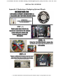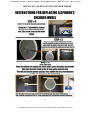
1
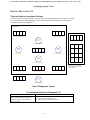
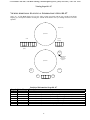
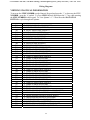
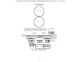
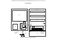
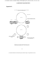
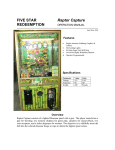
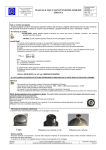
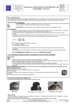
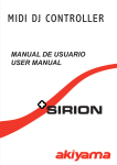
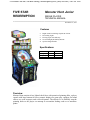
To Purchase This Item, Visit BMI Gaming | www.bmigaming.com | (800) 746-2255 | +561.391.7200
FIVE STAR
REDEEMPTION
Monster Hunt Junior
SINGLE PLAYER
TECHNICAL MANUAL
————————————————————————————————————
November 16, 2011
Features
•
•
•
•
•
Bright Attention Grabbing Graphics & Cabinet
Hot looking Lights
Exciting Super Fast Skill Stop
Oversized Highly Reliability Buttons
Operator Programmable
Specifications
Parameter
Voltage
Frequency
Weight
Value
115
60
600
Units
VAC
HZ
Pounds
Overview
Monster Hunt consists of two lighted clock faces with motorized spinning disks, a player
console with large buttons & levers, numeric displays for game play, speakers for sound
effects, two coin acceptors, and a ticket dispenser. The objective is to skillfully stop the
spinning disks so the player can attempt to accumulate trading cards or to maximize
points
To Purchase This Item, Visit BMI Gaming | www.bmigaming.com | (800) 746-2255 | +561.391.7200
TABLE OF CONTENTS
Features.............................................................................................................................. 1
Specifications ..................................................................................................................... 1
Overview ............................................................................................................................. 1
TABLE OF CONTENTS ................................................................................................... 2
Game Play .......................................................................................................................... 4
Program Mode.................................................................................................................... 5
Resetting the Statistics............................................................................................................................ 7
Diagnostics 71 – 72 ................................................................................................................................ 8
Diagnostic 71- 72 Position Type & Pie Slice Definition .................................................................... 8
How To Run Diagnostics 71 – 72 Calibrating Spinners......................................................................... 9
Step’s 71 – 72 Diagnostic Layout....................................................................................................... 9
Troubleshooting Steps for Diagnostics 71 - 72................................................................................... 9
Running Diagnostics 76........................................................................................................................ 10
Checking Spinner Motor .................................................................................................................. 10
Step 76 Diagnostic Layout ............................................................................................................... 10
Troubleshooting Steps for Diagnostic 76 ............................................................................................. 11
Running Diagnostics 77........................................................................................................................ 11
Display Keypad Inputs ..................................................................................................................... 11
Running Diagnostics 78........................................................................................................................ 11
Testing Ticket Dispenser .................................................................................................................. 11
Troubleshooting Steps for Diagnostic 78 ......................................................................................... 11
Running Diagnostics 79........................................................................................................................ 12
Testing for Spinner Intermittent Problems ....................................................................................... 12
Step 79 Diagnostic Layout ............................................................................................................... 12
Troubleshooting Steps for Diagnostic 79 ......................................................................................... 12
Viewing Additional Statistic al Information‘s Steps 80 - 87 ................................................................ 13
Statistical Information Steps 80 - 87 ................................................................................................ 13
STEP 99 Viewing Software Version .................................................................................................... 14
View and Changing Spinner Target Values .......................................................................... 15
Viewing and Changing Spinner Target Values Steps 100 – 576.......................................................... 15
Wiring DiagramsTop Level Interconnections ................................................................ 28
Figure 4 P2, P16, and P17 Connections From The VTMUX Board..................................................... 30
To The Control Panel P5 & P6 from Opto Board to The control Panel ............................................... 30
Bottom of Cabinet Lights ..................................................................................................................... 50
Appendix A ....................................................................................................................... 58
Self diagnostic #1 Test Layout ............................................................................................................ 58
Self Diagnostic #1 ................................................................................................................................ 59
Self Diagnostic #1 ERROR CODE CHART .................................................................................... 59
Appendix B Troubleshooting Assistance ........................................................................ 61
Troubleshooting Guide............................................................................................................ 61
Appendix C Replacing or Realigning Spinner Wheels................................................... 64
2
To Purchase This Item, Visit BMI Gaming | www.bmigaming.com | (800) 746-2255 | +561.391.7200
Appendix D....................................................................................................................... 67
Technical Assistance ............................................................................................................................ 67
Five Star Redemption....................................................................................................... 68
8835 Shirley Avenue ............................................................................................................................ 68
Northridge, CA 91324 ......................................................................................................................... 68
(818) 773-6057 Fax (818) 773-6064 .................................................................................................... 68
Parts Department Option 1 .............................................................................................................. 68
Technical Support Option 2............................................................................................................. 68
Sales Department Option 3 .............................................................................................................. 68
3
To Purchase This Item, Visit BMI Gaming | www.bmigaming.com | (800) 746-2255 | +561.391.7200
Game Play
Monster Club offers very fast and interesting play with many different strategies for
maximizing the points you can win.
Spinner# 1 allows the player to accumulate trading cards to win tickets or create an
opportunity to go to the Spinner# 2 to win tickets at higher levels possibly.
1) Insert coin(s) to ready the game for play.
2) Pull back the Start Lever to begin the Spinner Spinning.
3) There are several seconds in which to influence where the Spinner will stop by
skillfully pushing the Slow Stop button which decreases spinner speed or pulling back
on the Start Lever which will increase the spinner speed.
4) Points can be awarded and are displayed each time the Spinner is spun, however, you
may choose to go to the next level and take the points.
4
To Purchase This Item, Visit BMI Gaming | www.bmigaming.com | (800) 746-2255 | +561.391.7200
Program Mode
Program Mode allows the Game Operator the option of programming the Game by entering
data through the Control Panel, which is located on the front panel of the cabinet. This mode
includes viewing the game’s statistical data, running diagnostics, and changing game play
values.
To go into Program Mode, Hold Down both the ‘*’ and “#” symbols for approximately 5
seconds the Keypad Display should go Blank, next enter the number “11” which will allow
the game operator to go into Program Mode (Keypad should display all zero’s).
Pressing the FAST STOP BUTTON will decrement the Value, Pressing the SLOW STOP
BUTTON will increment the value. To increase the STEP NUMBER use the Numeric
Keypad and press the ‘*’, to decrease the STEP NUMBER press the ‘#’ symbol. To Go to
STEPS directly Hold down the “*” key while entering the STEP NUMBER in the keypad.
Pressing the Program Mode or Holding Down both the ‘*’ and “#” symbols will allow the
operator to exit. The program button is located near the main board inside of the cabinet.
5
To Purchase This Item, Visit BMI Gaming | www.bmigaming.com | (800) 746-2255 | +561.391.7200
Changing Program Values
CHANGING PROGRAM VALUES
To increase the STEP NUMBER use the Numeric Keypad and press the ‘*’, to decrease the
STEP NUMBER press the ‘#’ symbol. To Go to STEPS directly Hold down the “*” key
while entering the STEP NUMBER in the keypad. To View Spinner’s 1 – 2 Data Press the
SLOW STOP BUTTON to cycle through each spinner.
STEP #
DESCRIPTION
DESCRIPTION
0
1
2
3
4
5
Coins required to play
Attraction audio on time
Attraction audio off time
RPM1 speed before break is engageable
RPM2 speed before break is engageable
RPM1 SPEED to ENABLE DITHER
6
RPM2 SPEED to ENABLE DITHER
7
8
9
10
11
12
13
14
15
16
RPM1 Spinner cruising Speed
RPM2 Spinner cruising Speed
RPM1 spinner maximum hyper speed
RPM2 spinner maximum hyper speed
RPM1 speed to enable brake
RPM2 Speed to enable brake
RPM1 spinner maximum run time
RPM2 spinner maximum run time
Number of cards to enable thief
Action when thief not enabled
17
18
19
20
21
22
23
24
25
Auto spin Until Game Over
Consolation points when card repeated
Number CARDS TAKEN THIEF1
Number CARDS TAKEN THIEF2
Maximum points per game
Number points per ticket
Maximum spins Per Credit
Number cards to go higher
Action if card repeated
26
27
Demo mode
Enable keypad display
28
Play instructions during attraction
29
30
31
32
33
Timeout to go higher
Spinner diagnostic sensitivity
Extra_games_disable
Card_removal_order
Timeout_to_spin_with_credits
34
Timeout_to_spin_with_no_credits
35
Time alloted for Full throttle
36
37
38
39
40
41
42
43
44
45
46
Minimum for SMall jackpot spinner1
Minimum for BIG jackpot spinner1
Minimum for SMall jackpot spinner2
Minimum for BIG jackpot spinner2
Number of cards to enable cashout
Number of cards to enable trade in
RPM1 Spinner minum to enable kick
RPM2 spinner minim to enable kick
Spinner1 maximum number of kicks
Spinner2 maximum number of kicks
Spinner1 maximum kick time
Number of coins required to play
Number of seconds attraction audio is on (0 disables attraction audio)
Number of seconds attraction audio is off per attraction cycle
Spinner #1 RPM above which stop lever can cut motor power (increments of 1)
Spinner #2 RPM above which stop lever can cut motor power (increments of 1)
Spinner #1 RPM dither before enabling cutting motor power during ramp up
(increments of 1)
Spinner #2 RPM dither before enabling cutting motor power during ramp up
(increments of 1)
Spinner #1 cruising RPM (increments of 5)
Spinner #2 cruising RPM (increments of 5)
Spinner #1 maximum hyperspeed RPM (increments of 5)
Spinner #2 maximum hyperspeed RPM (increments of 5)
Spinner #1 RPM above which stop lever can energize brake (increments of 1)
Spinner #2 RPM above which stop lever can energize brake (increments of 1)
Maximum time before power is removed from spinner #1 motor (increments of 1)
Maximum time before power is removed from spinner #2 motor (increments of 1)
Number cards required to enable thief to take away cards (increments of 1)
Action if thief is not enabled where 1-25 number of free tickets, 26 = auto spin
(increments of 1)
0=do not auto spin, 1=auto spin until game is over (increments of 1)
Number of consolation points given when card is repeated (increments of 1)
Number of cards taken by thief1 (increments of 1)
Number of cards taken by thief2 (increments of 1)
Maximum number of points per game (increments of 25)
Number of points required per ticket dispensed (increments of 1)
Maximum number of spins per credit (increments of 1)
Number of cards taken to go higher (increments of 1)
Action if card repeated where 0=consolation points only, 1-10 = number auto
spins (increments of 1)
0=not demo mode, 1=demo mode
0=do not enable keypad display in game mode, 1=enable keypad display in game
mode
0=do not play instruction sound during attraction, 1=play instructions sounds
during attraction
Timeout to go higher where 1=12second, 2=15second, 3=20second, 4=25second
Spinner diagnostic sensitivity (1=most sensitive, 9=least sensitivity)
0=enable extra games, 1=disable extra games
1= left-to-right, 2=right-to-left, 3=most-recent
Time to push Start button before automatically spinning when player has credits
(increments of 1)
Time to push Start button before going to attraction when player has no credits
(increments of 1)
Time spinner must spin before the player can apply full-power to the spinner
(increments of 1)
Minimum points for small jackpot on spinner #1 (increments of 10)
Minimum points for big jackpot on spinner #1 (increments of 10)
Minimum points for jackpot on spinner #2 (increments of 10)
Number cards required to enable spinner cash out (increments of 1)
Number cards required to enable spinner tradein (increments of 1)
Number cards remaining after spinner tradein (increments of 1)
Spinner #1 RPM above which player can abort a stop (increments of 1)
Spinner #2 RPM above which player can abort a stop (increments of 1)
Spinner #1 maximum number of kicks allowed (increments of 1)
Spinner #2 maximum number of kicks allowed (increments of 1)
Spinner #1 maximum kick time allowed (increments of 1)
6
To Purchase This Item, Visit BMI Gaming | www.bmigaming.com | (800) 746-2255 | +561.391.7200
Changing Program Values
STEP #
47
48
49
50
51
52
54
55
56
57
58
59
60
61
62
63
64
65
66
67
68
69
DESCRIPTION
DESCRIPTION
Spinner2 maximum kick time
Swipe card to the top enable
Swipe to top coin
Dispense tickets during game play
Bank bate cashout enable
Bank bate ticket delay
Points for 01 cards
Points for 02 cards
Points for 03 cards
Points for 04 cards
Points for 05 cards
Points for 06 cards
Points for 07 cards
Points for 08 cards
Points for 09 cards
Points for 10 cards
Points for 11 cards
Points for 12 cards
Points for 13 cards
Points for 14 cards
Points for 15 cards
Points for 16 cards
Spinner #2 maximum kick time allowed (increments of 1)
0=disabled, 1=enabled
Number of times coin meter incremented for swipe to top (increments of 1)
0=disabled, 1=enabled
0=disabled, 1=enabled (enabled allows player to tear tickets off to cashout)
0=0.0 sec, 1=0.5 sec, 2=1.0 sec
Number of points awarded for 01 cards (increments of 1)
Number of points awarded for 02 cards (increments of 1)
Number of points awarded for 03 cards (increments of 1)
Number of points awarded for 04 cards (increments of 1)
Number of points awarded for 05 cards (increments of 1)
Number of points awarded for 06 cards (increments of 1)
Number of points awarded for 07 cards (increments of 1)
Number of points awarded for 08 cards (increments of 1)
Number of points awarded for 09 cards (increments of 1)
Number of points awarded for 10 cards (increments of 1)
Number of points awarded for 11 cards (increments of 1)
Number of points awarded for 12 cards (must be 0)
Number of points awarded for 13 cards (must be 0)
Number of points awarded for 14 cards (must be 0)
Number of points awarded for 15 cards (must be 0)
Number of points awarded for 16 cards (must be 0)
RESETTING THE STATISTICS
Pressing the FAST STOP BUTTON will execute the reset.
STEP #
DESCRIPTION
70
RESET STATISTICS
7
To Purchase This Item, Visit BMI Gaming | www.bmigaming.com | (800) 746-2255 | +561.391.7200
Changing Program Values
DIAGNOSTICS 71 – 72
During calibration (Steps 71-72
position pointer here
PIESLICE = 000
PIESLICE = 255
PIESLICE = 254
PIESLICE = 001
POSITION #00
POSITION #11
POSITION #01
POSITION #10
POSITION #02
POSITION #09
POSITION #03
POSITION #08
POSITION #04
POSITION #07
POSITION #05
POSITION #06
POINTS = 20
POSITION TYPE = GAME OVER
Diagnostic 71- 72 Position Type & Pie Slice Definition
8
To Purchase This Item, Visit BMI Gaming | www.bmigaming.com | (800) 746-2255 | +561.391.7200
Changing Program Values
HOW TO RUN DIAGNOSTICS 71 – 72 CALIBRATING SPINNERS
Displays Spinner Information Pie Slices 0-255, Position Type, Points, and Position Number.
Pulling back on the START LEVER will execute the Calibration of the Spinner.
GAME FRONT
DIAGNOSTIC KEYPAD
(p26b CARDS IN ANY ORDER)
(NOT USED IN THESE STEPS)
(p25c CARDS IN A ROW)
(NOT USED IN THESE STEPS)
(GO HIGHER
BUTTON)
STEP NUMBER
(NOT USED IN THESE STEPS)
(INSTRUCT
LEFT
BUTTON)
EXECUTE BUTTON
(INSTRUCT
RIGHT
BUTTON)
(p26d NUMBER CARDS COLLECTED)
(NOT USED IN THESE STEPS)
1
2
3
4
6
0
7
8
9
0
NEXT
STEP
(NOT USED IN THESE STEPS)
(TAKE
TICKETS
BUTTON)
*
PREV
STEP
#
(NOT USED IN THESE STEPS)
Note: Hold down ‘*” key and enter
step number to jump to a desired
program mode step.
(p26c RPM)
SPINNER PIE SLICE
(p25a POINTS JUST WON)
SPINNER POSITION NUMBER
(p26a CREDITS)
SPINNER POSITION POINTS
(CALL
ATTENDANT
BUTTON)
(p25b DISPENSE TICKET COUNT)
(NOT USED IN THESE STEPS)
(NOT USED IN THESE STEPS)
Step’s 71 – 72 Diagnostic Layout
Troubleshooting Steps for Diagnostics 71 - 72
Problem
Pie Slice is not zero when spinner is
pointing straight up to TDC (top dead
center)
Wrong Pie Slice 0-255, Pie Slice
number should increase smoothly from
0 to 255 as spinner is rotated clockwise
Wrong Position Number, Position
Number should increase smoothly from
0 as spinner is rotated clockwise
through each Spinner Position
Solution
• Recalibrate to TDC by manually positioning pointer straight up
and pushing Start button (spinner may be energized by
momentarily pushing Fast Stop pushbutton)
• Verify spinner board switches are set correctly
• Examine/reseat wiring harness connections to spinner board
• Verify spinner board switches are set correctly
• Examine/reseat wiring harness connections to spinner board
• Recalibrate to TDC (top dead center) by manually positioning
pointer straight up and pushing Fast Stop button
9
To Purchase This Item, Visit BMI Gaming | www.bmigaming.com | (800) 746-2255 | +561.391.7200
Changing Program Values
RUNNING DIAGNOSTICS 76
Checking Spinner Motor
Push Left Instruction Pushbutton to select desired spinner to test. The number of the selected spinner is
shown on the RPM display. Pulling the Start Lever to energize the spinner motor. Hold down the Slow Stop
Pushbutton while pushing the Start Lever to cause the spinner to spin more slowly. Perform the
troubleshooting steps in the sequence specified in Troubleshooting Steps for Diagnostic 76 on next page.
GAME FRONT
DIAGNOSTIC KEYPAD
(p26b CARDS IN ANY ORDER)
(NOT USED IN THESE STEPS)
(p25c CARDS IN A ROW)
(GO HIGHER
BUTTON)
STEP NUMBER
INC BUTTON
(INSTRUCT
LEFT
BUTTON)
(NOT USED IN THESE STEPS)
(INSTRUCT
RIGHT
BUTTON)
(p26d NUMBER CARDS COLLECTED)
(NOT USED IN THESE STEPS)
1
2
3
4
6
0
7
8
9
0
NEXT
STEP
(NOT USED IN THESE STEPS)
(TAKE
TICKETS
BUTTON)
*
PREV
STEP
#
DEC BUTTON
Note: Hold down ‘*” key and enter
step number to jump to a desired
program mode step.
(p26c RPM)
(NOT USED IN THESE STEPS)
(p25a POINTS JUST WON)
(NOT USED IN THESE STEPS)
(CALL
ATTENDANT
BUTTON)
(p25b DISPENSE TICKET COUNT)
(NOT USED IN THESE STEPS)
(NOT USED IN THESE STEPS)
Step 76 Diagnostic Layout
10
(p26a CREDITS)
PARAMETER VALUE
To Purchase This Item, Visit BMI Gaming | www.bmigaming.com | (800) 746-2255 | +561.391.7200
Changing Program Values
TROUBLESHOOTING STEPS FOR DIAGNOSTIC 76
Problem
Particular spinner(s) do not spin
Particular brake(s) do not activate
All spinners do not spin
All brakes do not activate
Solution
• Verify spinner board switches are set correctly
• Examine/reseat wiring harness connections to spinner boards
• Swap spinner boards to see if problem moves with the boards
and replace any spinner board found to be defective (be sure
board switches are set correctly)
• Replace spinner motor and retest
• Verify spinner board switches are set correctly
• Examine/reseat wiring harness connections to spinner boards
• Swap spinner boards to see if problem moves with the boards
and replace any spinner board found to be defective (be sure
board switches are set correctly)
• Adjust/replace spinner brake and retest
• Examine/reseat wiring harness connections to spinner boards
• Look for low-voltage changes at VTMux board output when
spinner should be spinning and if voltage does not change,
replace VTMux board and retest
• Examine/reseat wiring harness connections to spinner boards
• Look for low-voltage changes at VTMux board output when
brake should be activated and if voltage does not change, replace
VTMux board and retest
RUNNING DIAGNOSTICS 77
Display Keypad Inputs
Push each of the individual numbers on the keypad to display the associated keypad number.
RUNNING DIAGNOSTICS 78
Testing Ticket Dispenser
Push the Flashing Call Attendant Pushbutton to Dispense a Single Ticket.
Troubleshooting Steps for Diagnostic 78
Problem
Does not dispense tickets
Solution
• Clear ticket dispenser of any jammed tickets
• Load tickets if empty
• Try dispensing a ticket using diagnostic mode, if ticket does not
dispense:
o Check wiring harness
o Replace ticket dispenser and retest
o Replace VTMux board and retest
11
To Purchase This Item, Visit BMI Gaming | www.bmigaming.com | (800) 746-2255 | +561.391.7200
Changing Program Values
RUNNING DIAGNOSTICS 79
Testing for Spinner Intermittent Problems
Check for spinner intermittent problems while spinners are spinning. Momentarily press keypad 1-5 to begin
test on selected spinner. Press Keypad 0 to stop test. Perform the troubleshooting steps in the sequence
Troubleshooting Steps for Diagnostic 79.
GAME FRONT
DIAGNOSTIC KEYPAD
(p26b CARDS IN ANY ORDER)
(NOT USED IN THESE STEPS)
(p25c CARDS IN A ROW)
(NOT USED IN THESE STEPS)
(GO HIGHER
BUTTON)
STEP NUMBER
(NOT USED IN THESE STEPS)
(INSTRUCT
LEFT
BUTTON)
(INSTRUCT
RIGHT
BUTTON)
(p26d NUMBER CARDS COLLECTED)
(NOT USED IN THESE STEPS)
EXECUTE BUTTON
1
2
3
4
6
0
7
8
9
0
NEXT
STEP
(NOT USED IN THESE STEPS)
(TAKE
TICKETS
BUTTON)
*
PREV
STEP
#
(NOT USED IN THESE STEPS)
Note: Hold down ‘*” key and enter
step number to jump to a desired
program mode step.
(p26c RPM)
SPINNER PIE SLICE
(p25a POINTS JUST WON)
SPINNER POSITION NUMBER
(p26a CREDITS)
SPINNER POSITION POINTS
(CALL
ATTENDANT
BUTTON)
(p25b DISPENSE TICKET COUNT)
(NOT USED IN THESE STEPS)
(NOT USED IN THESE STEPS)
Step 79 Diagnostic Layout
Troubleshooting Steps for Diagnostic 79
Problem
Spinner errors detected (a couple errors
during a couple minutes of operation is
normal and will not cause problems in
game’s operation)
Solution
• Examine/reseat wiring harness connections to spinner boards
• Replace spinner board and retest
• Replace spinner mechanism and retest
12
To Purchase This Item, Visit BMI Gaming | www.bmigaming.com | (800) 746-2255 | +561.391.7200
Viewing Steps 80 - 87
VIEWING ADDITIONAL STATISTIC AL INFORMATION‘S STEPS 80 - 87
Step’s 80 – 87 The RPM display will give the Value or Data associated with the step, and the Total Points
Display gives the Spinner Number. Pressing the “SLOW STOP” Button will cycle through and select all of the
Spinners.
Steps 80 - 87
Spinner #2
Value
CURRENT
POINTS
(p25a)
[Spinner
Number]
RPM
(p25b)
TOTAL POINTS
(p26b)
SLOW
STOP
Press Down to
Sequence
Through Each
Spinner
Spinner #1
FAST
STOP
START
CREDITS (p26a)
INST
Step #
80
81
82
83
84
85
86
87
INST
Statistical Information Steps 80 - 87
Value Range Description
0-00,999,999
0-00,999,999
0-00,999,999
0-00,999,999
0-00,999,999
0-00,999,999
0-00,999,999
0-00,999,999
Number of Times Player Paid To Go Higher from Spinner #1-5 (Since Last Reset)
Number of Times Player Paid To Go Higher from Spinner #1-5 (Lifetime)
Number of Times Player Did Not Pay To Go Higher from Spinner #1-5 (Since Last Reset)
Number of Times Player Did Not Pay To Go Higher from Spinner #1-5 (Lifetime)
Number of Times Player Landed on Secret Passage from Spinner #1-5 (Since Last Reset)
Number of Times Player Landed on Secret Passage from Spinner #1-5 (Lifetime)
Number of Times Player Landed on Booby Trap from Spinner #1-5 (Since Last Reset)
Number of Times Player Landed on Booby Trap from Spinner #1-5 (Lifetime)
13
To Purchase This Item, Visit BMI Gaming | www.bmigaming.com | (800) 746-2255 | +561.391.7200
Viewing Steps 99
Software Version Identification
STEP 99 VIEWING SOFTWARE VERSION
Step 99 Displays the Eight Digit Software Identification Number on the Last Value Scored & RPM’s displays.
Step 99
Spinner #2
Software Identification
Value
CURRENT
POINTS
(p25a)
[Spinner
Number]
RPM
(p25b)
TOTAL POINTS
(p26b)
SLOW
STOP
Spinner #1
FAST
STOP
START
CREDITS (p26a)
INST
INST
14
To Purchase This Item, Visit BMI Gaming | www.bmigaming.com | (800) 746-2255 | +561.391.7200
View and Changing Spinner Target Values
VIEWING AND CHANGING SPINNER TARGET VALUES STEPS 100 – 576
Pressing the FAST STOP BUTTON will decrement the Value, Pressing the START BUTTON will increment the
value. To increase the STEP NUMBER use the Numeric Keypad and press the ‘*’, to decrease the STEP
NUMBER press the ‘#’ symbol. To Go to STEPS directly Hold down the “*” key while entering the STEP
NUMBER in the keypad. Pressing the Program Mode or Holding Down both the ‘*’ and “#” symbols will allow the
operator to exit. The program button is located near the main board inside of the cabinet.
26
0
18
9
STEPS 100 - 126
VIEWING SPINNER #1 TARGET POINTS
STEP
NUMBER
SPINNER #1
100
101
102
103
104
105
106
107
108
109
110
111
112
113
114
115
116
117
118
119
SPINNER
POSITION
TARGET
POINTS
0
INCREMENTS
OF 1
1
2
3
4
5
6
7
8
9
10
11
12
13
14
15
16
17
18
19
“
“
“
“
“
“
“
“
“
“
“
“
“
“
“
“
“
“
“
15
To Purchase This Item, Visit BMI Gaming | www.bmigaming.com | (800) 746-2255 | +561.391.7200
STEP
NUMBER
SPINNER #1
120
121
122
123
124
125
126
SPINNER
POSITION
20
21
22
23
24
25
26
16
TARGET
POINTS
“
“
“
“
“
“
“
To Purchase This Item, Visit BMI Gaming | www.bmigaming.com | (800) 746-2255 | +561.391.7200
View and Changing Spinner Target Values
26
0
18
9
STEPS 150 - 176
CHANGING SPINNER #1 TARGET TYPES
STEP
NUMBER
SPINNER #1
150
151
152
153
154
155
156
157
158
159
160
161
162
163
164
165
166
167
168
169
170
171
172
173
174
175
176
SPINNER
POSITION
0
1
2
3
4
5
6
7
8
9
10
11
12
13
14
15
16
17
18
19
20
21
22
23
24
25
26
17
TARGET
TYPES
0=NONE
1-5 JUMP TO
SPINNER#
6=UP
7 = DOWN
8= DEATH
“
“
“
“
“
“
“
“
“
“
“
“
To Purchase This Item, Visit BMI Gaming | www.bmigaming.com | (800) 746-2255 | +561.391.7200
View and Changing Spinner Target Values
26
0
18
9
STEPS 200 - 226
VIEWING SPINNER #2 TARGET POINTS
STEP
NUMBER
SPINNER #1
200
201
202
203
204
205
206
207
208
209
210
211
212
213
214
215
216
217
218
219
220
221
222
223
224
225
226
SPINNER
POSITION
TARGET
POINTS
0
INCREMENTS
OF 5
1
2
3
4
5
6
7
8
9
10
11
12
13
14
15
16
17
18
19
20
21
22
23
24
25
26
“
“
“
“
“
“
“
“
“
“
“
“
“
“
“
“
“
“
“
“
“
“
“
“
“
“
18
To Purchase This Item, Visit BMI Gaming | www.bmigaming.com | (800) 746-2255 | +561.391.7200
View and Changing Spinner Target Values
26
0
18
9
STEPS 250 - 276
CHANGING SPINNER #2 TARGET TYPES
STEP
NUMBER
SPINNER #1
250
251
252
253
254
255
256
257
258
259
260
261
262
263
264
265
266
267
268
269
270
271
272
273
274
275
276
SPINNER
POSITION
TARGET TYPES
0=NONE
1-5 JUMP TO
SPINNER#
6=UP
7 = DOWN
8= DEATH
9=DEAD ZONE
10= UP DEAD ZONE
0
1
2
3
4
5
6
7
8
9
10
11
12
13
14
15
16
17
18
19
20
21
22
23
24
25
26
“
“
“
“
“
“
“
“
“
“
“
“
“
“
“
“
“
“
“
“
“
“
“
“
“
“
19
To Purchase This Item, Visit BMI Gaming | www.bmigaming.com | (800) 746-2255 | +561.391.7200
View and Changing Spinner Target Values
12
0
9
6
STEPS 300 - 312
CHANGING SPINNER #3 TARGET POINTS
STEP
NUMBER
SPINNER #1
300
301
302
303
304
305
306
307
308
309
310
311
312
SPINNER
POSITION
TARGET
POINTS
0
INCREMENTS
OF 1
1
2
3
4
5
6
7
8
9
10
11
12
“
“
“
“
“
“
“
“
“
“
“
“
20
To Purchase This Item, Visit BMI Gaming | www.bmigaming.com | (800) 746-2255 | +561.391.7200
View and Changing Spinner Target Values
12
0
9
6
STEPS 350 - 362
CHANGING SPINNER #1 TARGET TYPES
STEP
NUMBER
SPINNER #1
350
351
352
353
354
355
356
357
358
359
360
361
362
SPINNER
POSITION
TARGET TYPES
0
0=NONE
1-5 JUMP TO
SPINNER#
6=UP
7 = DOWN
8= DEATH
9=DEAD ZONE
10= UP DEAD ZONE
1
2
3
4
5
6
7
8
9
10
11
12
“
“
“
“
“
“
“
“
“
“
“
“
21
To Purchase This Item, Visit BMI Gaming | www.bmigaming.com | (800) 746-2255 | +561.391.7200
View and Changing Spinner Target Values
26
0
18
9
STEPS400 - 426
VIEWING SPINNER #4 TARGET POINTS
STEP
NUMBER
SPINNER #1
400
401
402
403
404
405
406
407
408
409
410
411
412
413
414
415
416
417
418
419
420
421
422
423
424
425
426
SPINNER
POSITION
TARGET
POINTS
0
INCREMENTS
OF 1
1
2
3
4
5
6
7
8
9
10
11
12
13
14
15
16
17
18
19
20
21
22
23
24
25
26
“
“
“
“
“
“
“
“
“
“
“
“
“
“
“
“
“
“
“
“
“
“
“
“
“
“
22
To Purchase This Item, Visit BMI Gaming | www.bmigaming.com | (800) 746-2255 | +561.391.7200
View and Changing Spinner Target Values
26
0
18
9
STEPS 450 - 476
CHANGING SPINNER #4 TARGET TYPES
STEP
NUMBER
SPINNER #1
450
451
452
453
454
455
456
457
458
459
460
461
462
463
464
465
466
467
468
469
470
471
472
473
474
475
476
SPINNER
POSITION
TARGET TYPES
0
0=NONE
1-5 JUMP TO
SPINNER#
6=UP
7 = DOWN
8= DEATH
9=DEAD ZONE
10= UP DEAD ZONE
1
2
3
4
5
6
7
8
9
10
11
12
13
14
15
16
17
18
19
20
21
22
23
24
25
26
“
“
“
“
“
“
“
“
“
“
“
“
“
“
“
“
“
“
“
“
“
“
“
“
“
“
23
To Purchase This Item, Visit BMI Gaming | www.bmigaming.com | (800) 746-2255 | +561.391.7200
View and Changing Spinner Target Values
0
1
2
11
10
3
9
4
8
5
7
6
STEPS500 - 526
VIEWING SPINNER #4 TARGET POINTS
STEP
NUMBER
SPINNER #1
500
501
502
503
504
505
506
507
508
509
510
511
512
513
514
515
516
517
518
519
520
521
522
523
524
525
526
SPINNER
POSITION
TARGET
POINTS
0
INCREMENTS
OF 1
1
2
3
4
5
6
7
8
9
10
11
12
13
14
15
16
17
18
19
20
21
22
23
24
25
26
“
“
“
“
“
“
“
“
“
“
“
“
“
“
“
“
“
“
“
“
“
“
“
“
“
“
24
To Purchase This Item, Visit BMI Gaming | www.bmigaming.com | (800) 746-2255 | +561.391.7200
0
1
2
11
10
3
9
4
8
5
7
6
STEPS 550 - 576
CHANGING SPINNER #5 TARGET TYPES
STEP
NUMBER
SPINNER #1
550
551
552
553
554
555
556
557
558
559
560
561
562
563
564
565
566
567
568
569
570
571
572
573
574
575
576
SPINNER
POSITION
TARGET TYPES
0
0=NONE
1-5 JUMP TO
SPINNER#
6=UP
7 = DOWN
8= DEATH
9=DEAD ZONE
10= UP DEAD ZONE
1
2
3
4
5
6
7
8
9
10
11
12
13
14
15
16
17
18
19
20
21
22
23
24
25
26
“
“
“
“
“
“
“
“
“
“
“
“
“
“
“
“
“
“
“
“
“
“
“
“
“
“
To Purchase This Item, Visit BMI Gaming | www.bmigaming.com | (800) 746-2255 | +561.391.7200
Wiring Diagrams
VIEWING STASTICAL INFORMATION
To increase the STEP NUMBER use the Numeric Keypad and press the ‘*’, to decrease the STEP
NUMBER press the ‘#’ symbol. To Go to STEPS directly Hold down the “*” key while entering
the STEP NUMBER in the keypad. To View Spinner’s 1 – 5 Data Press the SLOW STOP
BUTTON to cycle through each spinner.
STEP #
700
701
702
703
704
705
706
707
708
709
710
711
712
713
714
715
716
717
718
719
720
721
722
723
724
725
726
727
728
729
750
751
752
753
754
755
756
757
DESCRIPTION
R COINS TAKEN IN (SINCE RESET)
L COINS TAKEN IN (LIFETIME)
R TOTAL SPINS (SINCE RESET)
L TOTAL SPINS (LIFETIME)
R POINTS WON (SINCE RESET)
L POINTS WON (LIFETIME)
R CREDITS (SINCE RESET)
L CREDITS (LIFETIME)
R TICKETS (SINCE RESET)
L TICKETS (LIFETIME)
R TIMES 1CARDS (SINCE RESET)
L TIMES 1CARDS (LIFETIME)
R TIMES 2CARDS (SINCE RESET)
L TIMES 2CARDS (LIFETIME)
R TIMES 3CARDS (SINCE RESET)
L TIMES 3CARDS (LIFETIME)
R TIMES 4CARDS (SINCE RESET)
L TIMES 4CARDS (LIFETIME)
R TIMES 5CARDS (SINCE RESET)
L TIMES 5CARDS (LIFETIME)
R TIMES 6CARDS (SINCE RESET)
L TIMES 6CARDS (LIFETIME)
R TIMES 7CARDS (SINCE RESET)
L TIMES 7CARDS (LIFETIME)
R TIMES 8CARDS (SINCE RESET)
L TIMES 8CARDS (LIFETIME)
R TIMES 9CARDS (SINCE RESET)
L TIMES 9CARDS (LIFETIME)
R TIMES 10CARDS (SINCE RESET)
L TIMES 10CARDS (LIFETIME)
R TIMES SPINNER TAMPERED0-4 (SINCE RESET)
L TIMES SPINNER TAMPERED0-4 (LIFETIME)
R TIMES SPINNER SPUN0-4 (SINCE RESET)
L TIMES SPINNER SPUN0-4 (LIFETIME)
R POINTS SPINNER0-4 (SINCE RESET)
L POINTS SPINNER0-4 (LIFETIME)
R TIMES SPUN ON POINTS0-4 (SINCE RESET)
L TIMES SPUN ON POINTS0-4 (LIFETIME)
26
To Purchase This Item, Visit BMI Gaming | www.bmigaming.com | (800) 746-2255 | +561.391.7200
Wiring Diagrams
STEP #
758
759
780
781
782
783
784
785
786
787
DESCRIPTION
R TIMES PAY HIGHER0-4 (SINCE RESET)
L TIMES PAY HIGHER0-4 (LIFETIME)
R AVERAGE POINTS PER CREDIT (SINCE RESET)
L AVERAGE POINTS PER CREDIT (LIFETIME)
R AVERAGE SPINS PER CREDIT (SINCE RESET)
L AVERAGE SPINS PER CREDIT (LIFETIME)
R AVERAGE POINTS SPINNER0-4 (SINCE RESET)
L AVERAGE POINTS SPINNER0-4 (LIFETIME)
R AVERAGE POINTS CREDITS0-4 (SINCE RESET)
L AVERAGE POINTS CREDITS0-4 (LIFETIME)
27
To Purchase This Item, Visit BMI Gaming | www.bmigaming.com | (800) 746-2255 | +561.391.7200
Wiring DiagramsTop Level Interconnections
TOP LEVEL INTERCONNECT DIAGRAM
120 VAC
120 VAC
Neon Transformer for Spinner
Light Ring #1
Spinner Assembly #1
Motor/
Neon
Light Ring
Shaft
#1
Encoder
#1
W41
W40
J3
Neon Transformer for Spinner
Light Ring #2
Spinner Assembly #2
Motor/
Neo
Light
n Ring
Shaf
#
Encoder
t
2
#2
1
#
e d
k o
i
a
rB n
e
lo
S
W42
J6
W50
J5
Smart Spinner Board #1
J1
W51
J3
2
#
e d
k o
i
a
n
rB e
l
o
S
W52
J6
J5
Smart Spinner Board #2
J4
J1
J4
W14
W34
RPM
W30
3 SSRs and Rail/
Cabinet Neons
From POS terminal of
+13.7 VDC Power Supply
P24
P5
P34
P36
8 SSRs and Neons
W23
P17
P32
Credits
W24
P18
P29
P25
W12
W11
W10
Cost To Go Higher
W40
W41
8051 VTMux Board
(Note: connectors not show in actual locations on PCB)
P1
J1
J2
P31
Speakers
W42
P23
W22
J1
P22
W21
P2
W20
P16
W19
P3
W18
P19
P43
W1
P30
W17
W2
P12
P28
W16
Total Points (Collected Card Value)
Small 4-digit displays
P26
W35
Number Cards Collected
W1
3
W28
W29
W43
Keypad
P4
W15
Dispense Ticket Count
W4
Audio
W45
See supplemental drawing for
desired configuration (single,
multi-player, grand)
Bill Acceptor
(optional)
W27
Trading Card Lights
09-12
Trading Card Lights
01-08
Lighted Pushbuttons
Add Credit, Coin
Acceptor, Jackpot
Lights
Coin Acceptors,
Prog Switch, and
Jumpers
le
ve
L
p
o
T
e
e
s
(
re
sn
e
p
si
D
te
kc
iT
o
T
n
o
2
/2
g
p
m
a
rg
a
i
D
tc
e
n
n
o
rc
e
tn
I
Coin Meter. Tickets
Low LED
)e
g
a
p
g
n
i
w
o
ll
o
f
P9
Ticket Meter
(may optionally be connected
to VTMux board)
Opto Board
(Ticket Dispenser
Sensors)
Ticket Meter
P7
W25
TOUT
SNS1
TLOW
SNS2
W3
+
120 VAC
W44
P8
W26
Ticket
Dispenser
Motor
Ticket
Dispenser
Assembly
P3
P2
Ticket Dispenser
Control Board
-
13.7 VDC Power
Supply
fuse
FIGURE 1 – TOP LEVEL INTERCONNECT DIAGRAM
From POS terminal of
+13.7 VDC Power Supply
To Purchase This Item, Visit BMI Gaming | www.bmigaming.com | (800) 746-2255 | +561.391.7200
Wiring Diagrams
SPINNER #2 and Neon Ring
SPINNER #1 and Neon Ring
CARD
“10”
CARD
“09”
M
O
CARD
“08”
CARD
“07”
CARD
“06”
CARD
“05”
CARD
“04”
CARD
“03”
CARD
“02”
CARD
“01”
N
S
T
E
R
W
I
N
INSTRUCTION LEFT
BUTTON
SUPER JACKPOT LIGHT
INSTRUCTION RIGHT
BUTTON
COST TO GO HIGHER
USE CARDS TO GO
HIGHER LIGHTED
PUSHBUTTON
CASH OUT LIGHTED
PUSHBUTTON
NUMBER CARDS COLLECTED
STOP LIGHTED LEVER
USE CREDITS TO GO
HIGHER LIGHTED
PUSHBUTTON
START LIGHTED LEVER
ADD CREDIT LIGHT
RPM
TOTAL POINTS
Ticket Dispenser
CREDITS
Coin Acceptors
DISPENSE TICKET COUNT
TICKETS LOW
CALL
ATTN
INSERT COINS
FIGURE 2 – CONTROL PANEL
29
To Purchase This Item, Visit BMI Gaming | www.bmigaming.com | (800) 746-2255 | +561.391.7200
Wiring Diagrams
FIGURE 4 P2, P16, AND P17 CONNECTIONS FROM THE VTMUX BOARD
TO THE CONTROL PANEL P5 & P6 FROM OPTO BOARD TO THE CONTROL PANEL
30
To Purchase This Item, Visit BMI Gaming | www.bmigaming.com | (800) 746-2255 | +561.391.7200
Wiring Diagrams
FIGURE 5 CONNECTIONS TO THE CONTROL PANEL
31
To Purchase This Item, Visit BMI Gaming | www.bmigaming.com | (800) 746-2255 | +561.391.7200
Wiring Diagrams
FIGURE 6 VTMUX BOARD P32 TO SMART SPINNER BOARD #1 & 2, J4S W34
32
To Purchase This Item, Visit BMI Gaming | www.bmigaming.com | (800) 746-2255 | +561.391.7200
Wiring Diagrams
FIGURE 7 POWER SUPPLY TO SPINNER BOARDS #1 & 2 J1S7
W30 VTMUX BOARD P5, 24, AND 13.7VDC
33
To Purchase This Item, Visit BMI Gaming | www.bmigaming.com | (800) 746-2255 | +561.391.7200
Wiring Diagrams
FIGURE 7 POWER SUPPLY TO SPINNER BOARDS #1 & 2 J1S7
W30 VTMUX BOARD P5, 24, AND 13.7VDC
34
To Purchase This Item, Visit BMI Gaming | www.bmigaming.com | (800) 746-2255 | +561.391.7200
Wiring Diagrams
FIGURE 7 POWER SUPPLY TO SPINNER BOARDS #1 & 2 J1S7
W30 VTMUX BOARD P5, 24, AND 13.7VDC
35
To Purchase This Item, Visit BMI Gaming | www.bmigaming.com | (800) 746-2255 | +561.391.7200
Wiring Diagrams
36
To Purchase This Item, Visit BMI Gaming | www.bmigaming.com | (800) 746-2255 | +561.391.7200
Wiring Diagrams
Spinner #1 Mounting Plate
Plugs into
Smart Spinner
Board #1 J6
J6
Top View
1
2
1
2
BRN
W41
18 AWG wire
Spinner Motor Power
Spinner Motor Ground
RED
Dot
350428-1
18 AWG wire
YEL
J1
Motor
(rear view--looking at
wiring end)
1
2
3
4
5
6
7
8
9
10
11
key
W30
Motor, solenoid,
spinner selects,
spinner ready
signals (daisy chain
signals to/from
VTMux Board P24)
Plugs into
Smart Spinner
Board #1 J5
(Solenoid comes with the
two black wires attacted)
W42
J5
Top View
1
2
3
Solenoid Power, BLK
Solenoid Ground, BLK
1
2
3
Smart
Spinner
Board
#1
Solenoid
18 AWG wire
350429-1
Plugs into
Smart Spinner
Board #1 J3
J4
W34
J3
1
2
3
Encoder Signals
(ribbon cable to
VTMux Board P32)
5
2
5
7
5
7
9
7
9
12
9
10
11
12
13
14
8
10
11
13
6
8
10
11
4
6
8
1
12
2
Ground
Encoder Bit 1
Encoder Bit 2
Encoder Bit 3
Encoder Bit 4
Encoder Bit 5
Encoder Bit 6
Encoder Bit 7
Encoder Bit 8
13
14
Top View
2
3
4
6
VCC
1
3
4
W40
Top View
1
3
4
5
6
7
8
9
10
11
12
13
14
14
Plugs into
Encoder Board
#1 J1
FIGURE 8 SPINNER #1 SUBASSEMBLY
W40 SPINNER BOARD #1 J3 TO ENCODER BOARD #1 J1
W41 SPINNER BOARD #1 J6 TO SPINNER MOTOR
W42 SPINNER BOARD #1 J5 TO SPINNER SOLENOID
37
Encoder
Board
#1
To Purchase This Item, Visit BMI Gaming | www.bmigaming.com | (800) 746-2255 | +561.391.7200
Spinner #2 Mounting Plate
Plugs into
Smart Spinner
Board #2 J6
J6
Top View
1
2
1
2
BRN
W51
18 AWG wire
Spinner Motor Power
Spinner Motor Ground
RED
Dot
350428-1
18 AWG wire
YEL
J1
Motor
(rear view--looking at
wiring end)
1
2
3
4
5
6
7
8
9
10
11
key
W30
Motor, solenoid,
spinner selects,
spinner ready
signals (daisy chain
signals to/from
VTMux Board P24)
Plugs into
Smart Spinner
Board #2 J5
(Solenoid comes with the
two black wires attacted)
W52
J5
Top View
1
2
3
1
2
3
Smart
Spinner
Board
#2
Solenoid Power, BLK
Solenoid Ground, BLK
Solenoid
18 AWG wire
350429-1
Plugs into
Smart Spinner
Board #2 J3
J4
W34
1
1
2
3
Encoder Signals
(ribbon cable to
VTMux Board P32)
5
2
4
6
9
6
9
12
9
10
11
12
13
14
8
10
11
13
6
7
8
10
11
4
5
7
8
1
12
2
Ground
Encoder Bit 1
Encoder Bit 2
Encoder Bit 3
Encoder Bit 4
Encoder Bit 5
Encoder Bit 6
Encoder Bit 7
Encoder Bit 8
13
14
Top View
2
3
5
7
VCC
1
3
4
W50
Top View
J3
3
4
5
6
7
8
9
10
11
12
13
14
14
Plugs into
Encoder Board
#2 J1
FIGURE 9 SPINNER #2 SUBASSEMBLY
W40 SPINNER BOARD #2 J3 TO ENCODER BOARD #2 J1
W41 SPINNER BOARD #2 J6 TO SPINNER MOTOR
W42 SPINNER BOARD #2 J5 TO SPINNER SOLENOID
Encoder
Board
#2
To Purchase This Item, Visit BMI Gaming | www.bmigaming.com | (800) 746-2255 | +561.391.7200
FIGURE 15 SPINNER’S 1 – 2 NEON RINGS WIRING
To Purchase This Item, Visit BMI Gaming | www.bmigaming.com | (800) 746-2255 | +561.391.7200
Wiring Diagrams
W35 VTMUX BOARD P29 TO SPINNER #1-2 NEON TRANSFORMERS AND LIGHTS
40
To Purchase This Item, Visit BMI Gaming | www.bmigaming.com | (800) 746-2255 | +561.391.7200
(Solenoid comes with the
two black wires attacted)
W19
Top View
Plugs into
VTMux Board P34
1
2
3
Solenoid Power, BLK
Solenoid Ground, BLK
Solenoid
18 AWG wire
Molex 09503031 plug housing
Molex 08520072 crimp contact, 18-20 AWG
End View
FIGURE 16 VTMUX BOARD P34 TO BRAKE SOLENOID
25 Ohm, 10 Watt
Note: This is a 50 Ohm
potentiometer on prototypes.
BRN
W18
Top View
Plugs into
VTMux Board P36
1
2
3
Spinner Motor Power
18 AWG wire
BRN
RED
Dot
Spinner Motor Ground
18 AWG wire
YEL
Molex 09503031 plug housing
Molex 08520072 crimp contact, 18-20 AWG
Motor
(rear view--looking at wiring end)
End View
FIGURE 17 VTMUX BOARD P34 TO SPINNER MOTOR
41
*** All Technical Information Contained in this Operations Manual is Subject to Change Without Prior Notice.
To Purchase This Item, Visit BMI Gaming | www.bmigaming.com | (800) 746-2255 | +561.391.7200
Wiring Diagrams
W17
Top View
Plugs into
VTMux Board P32
1
key
key
4
5
6
7
8
9
10
11
12
Top View
VCC
1
key
key
4
5
6
7
8
9
10
11
12
Ground
Encoder Bit 1
Encoder Bit 2
Encoder Bit 3
Encoder Bit 4
Encoder Bit 5
Encoder Bit 6
Encoder Bit 7
Encoder Bit 8
Amp 1-640620-2 or
Panduit CE100F22-12-C
(for 22 AWG Wire)
Plugs into
Encoder Board J1
Amp 1-640620-2 or
Panduit CE100F22-12-C
(for 22 AWG Wire)
End View
End View
FIGURE 18 VTMUX BOARD P32 TO SPINNER SHAFT ENCODER
42
To Purchase This Item, Visit BMI Gaming | www.bmigaming.com | (800) 746-2255 | +561.391.7200
Wiring Diagrams
43
To Purchase This Item, Visit BMI Gaming | www.bmigaming.com | (800) 746-2255 | +561.391.7200
Wiring Diagrams
FIGURE 19 CONTROL PANEL DISPLAY
44
To Purchase This Item, Visit BMI Gaming | www.bmigaming.com | (800) 746-2255 | +561.391.7200
Wiring Diagrams
FIGURE 19 TICKETS DISPLAY
45
To Purchase This Item, Visit BMI Gaming | www.bmigaming.com | (800) 746-2255 | +561.391.7200
Wiring Diagrams
Figure 19 Topper Lights Wiring
46
To Purchase This Item, Visit BMI Gaming | www.bmigaming.com | (800) 746-2255 | +561.391.7200
Wiring Diagrams
FIGURE 19 RAIL WIRING 120 VAC
47
To Purchase This Item, Visit BMI Gaming | www.bmigaming.com | (800) 746-2255 | +561.391.7200
Wiring Diagrams
FIGURE 19 TOPPER LIGHTS WIRING
48
To Purchase This Item, Visit BMI Gaming | www.bmigaming.com | (800) 746-2255 | +561.391.7200
Wiring Diagrams
FIGURE 19 INSIDE BAYINET LIGHTS
49
To Purchase This Item, Visit BMI Gaming | www.bmigaming.com | (800) 746-2255 | +561.391.7200
Wiring Diagrams
“B” Molex
“A” Molex
Lights
“B” Molex
“A” Molex
Lights
“B” Molex
“A” Molex
Lights
“B” Molex
“A” Molex
Lights
“B” Molex
“A” Molex
Lights
“B” Molex
“A” Molex
Lights
“B” Molex
“A” Molex
Lights
“B” Molex
“A” Molex
Lights
+
BOTTOM OF CABINET LIGHTS
50
To Purchase This Item, Visit BMI Gaming | www.bmigaming.com | (800) 746-2255 | +561.391.7200
Wiring Diagrams
Top View
Plugs into
VTMux Board P3
1
2
key
4
key
6
7
8
9
10
11
12
W18
Ground
Program Mode Button
Coin Acceptor #1
Coin Acceptor #2
Four Spinners Present
Single Player Game
Center Game
These wires solder
to Program Mode
Button and Coin
Acceptor(s)
(For multi-player
games only)
Amp 1-640620-2 or
Panduit CE100F22-12-C
(for 22 AWG Wire)
End View
FIGURE 20 VTMUX BOARD P3 TO PROGRAM MODE BUTTON, SINGLE PLAYER,
AND COIN ACCEPTOR
51
To Purchase This Item, Visit BMI Gaming | www.bmigaming.com | (800) 746-2255 | +561.391.7200
Wiring Diagrams
W1
Plugs into P5 of Diode Board #1
Plugs into P42 of VTMux Board
16 AWG Black Wire
Female
Faston Tab
Female
Faston Tab
W2
Plugs into P40 of VTMux Board
Plugs into P5 of Diode Board #2
16 AWG Black Wire
Female
Faston Tab
Female
Faston Tab
W3
Plugs into P5 of Diode Board #3
Plugs into P38 of VTMux Board
16 AWG Black Wire
Female
Faston Tab
Female
Faston Tab
FIGURE 21 VTMUX BOARD P42, P40, AND P38 TO DIODE BOARDS P5S
52
To Purchase This Item, Visit BMI Gaming | www.bmigaming.com | (800) 746-2255 | +561.391.7200
Wiring Diagrams
FIGURE 23A 60-PIN RIBBON CABLE TEE TO DIODE BOARD #2 P7
FIGURE 23B 60-PIN RIBBON CABLE TEE TO DIODE BOARD #3 P7
W 10
(Plugs into VTMux Board P19)
(Ring lugs fasten to
binding posts on 13.7
VDC power supply-logic power)
BLK
2
RED
1
16 AWG Wire
Mate-N-Loc plug
Amp 350777-1
Molex 50-84-1025
Mate-N-Loc contacts, socket, 14-20 AWG
Amp 350550
Molex 02-08-1002
FIGURE 24 13.7 VDC POWER SUPPLY TO 8051 VTMUX BOARD P19
W 11
BLK
4
BLK
(Ring lugs fasten to
binding posts on 13.7
VDC power supply-lights/motors power)
3
RED
2
RED
1
16 AWG Wire
(Plugs into VTMux Board P43)
Mate-N-Loc plug
Amp 350779-1
Molex 50-84-1045
Mate-N-Loc contacts, socket, 14-20 AWG
Amp 350550
Molex 02-08-1002
FIGURE 25 -13.7 VDC POWER SUPPLY TO 8051 VTMUX BOARD P43
330K 1/4W Carbon
Comp
Screws to
Negative Power
Supply Terminal
W60
Screw to
unpainted surface
of chassis
16 AWG Black Wire
Ring Lug
0.047 uF
Mylar Film X7R
FIGURE 26 CHASSIS GROUND
53
Ring Lug
To Purchase This Item, Visit BMI Gaming | www.bmigaming.com | (800) 746-2255 | +561.391.7200
Wiring Diagrams
W41
Screw to
unpainted surface
of chassis
Plugs into P1 of VTMux Board
16 AWG Black Wire
Female
Faston Tab
Ring Lug
FIGURE 27 - AUDIO GROUND
54
To Purchase This Item, Visit BMI Gaming | www.bmigaming.com | (800) 746-2255 | +561.391.7200
Wiring Diagrams
Total Points
small display p26b
(rear view)
J1
Plugs into Creditssmall display
J1
Credits
small display p26a
(rear view)
Plugs into
VTMux Board
P26
W10
J1
8-conductor Modular Cable
Female
8-Pin
J2
8
Top View
Amp 0-640620-8 or
Panduit CE100F22-8-C
(for 22 AWG Wire)
W9
RPM
small display p25b
(rear view)
J1
End View
1
8
7
6
5
4
3
2
1
End View
1
8
7
6
5
4
3
2
1
8
Female
8-Pin
J2
Top View
Amp 0-640620-8 or
Panduit CE100F22-8-C
(for 22 AWG Wire)
Plugs into Current Points small
display J1
Current Points
small display p25a
(rear view)
Plugs into
VTMux Board
P25
W26
J1
8-conductor Modular Cable
Female
8-Pin
Amp 0-640620-8 or
Panduit CE100F22-8-C
(for 22 AWG Wire)
J2
8
Top View
W27
End View
1
8
7
6
5
4
3
2
1
End View
1
8
7
6
5
4
3
2
1
8
J2
Top View
Amp 0-640620-8 or
Panduit CE100F22-8-C
(for 22 AWG Wire)
FIGURE 28A VTMUX BOARD P26 TO CREDITS SMALL DISPLAY J1
FIGURE 28B VTMUX BOARD P25 TO CURRENT POINTS SMALL DISPLAY J2
55
Female
8-Pin
To Purchase This Item, Visit BMI Gaming | www.bmigaming.com | (800) 746-2255 | +561.391.7200
Wiring Diagrams
Select Prize
small display
(rear view)
1
J2
8
7
6
5
4
3
2
1
8
J1
End View
Top View
Amp 0-640620-8 or
Panduit CE100F22-8-C
(for 22 AWG Wire)
W22
End View
1
2
3
4
5
Amp 0-640620-5 or
Panduit CE100F22-5-C
(for 22 AWG Wire)
Top View
GUMB1
1
5
W8
Plugs into
VTMux Board J2
20-conductor Ribbon Cable
Assembly
Keypad with small
piggy-back interface
board
(Rear View)
Female
20-Pin
Female
20-Pin
Key
FIGURE 29A – VTMUX BOARD J2 TO KEYPAD KEY
FIGURE 29B - KEYPAD GUMB1 TO SELECT PRIZE SMALL DISPLAY J2
56
To Purchase This Item, Visit BMI Gaming | www.bmigaming.com | (800) 746-2255 | +561.391.7200
Wiring Diagrams
CABINET
(METAL FRAME)
Vend Tray #1
CLEAR WINDOW
Vend Tray #2
Vend Tray #3
DOOR
(REAR VIEW)
3rd wire of power cord
connects building
Protective Ground
Neon
Transformer
Drop Box
Note 1
+
Coin Acceptor
and
Coin Box
Note 1
Note 1
-
VTMux Board
Power
Supply #1
W101
GREEN
AWG 12
WOOD PANEL
GREEN
AWG 12
W109
Note 1
DOOR FRAME
(METAL)
GREEN
AWG 12
#10 x ½" panhead slotted screw
#10 split-ring washer
#10 flat washer
#10 crimp ring lug
W102
Note 1:
Note 1
Grind paint off
painted surface
FIGURE 30 - PROTECTIVE GROUND WIRING
57
FLOOR
(METAL)
W109 Required on nonmetal terminal strips only:
Rework terminal strip to add
green 12 AWG wire from
internal protective ground to
external ring lug for
connection to game floor.
To Purchase This Item, Visit BMI Gaming | www.bmigaming.com | (800) 746-2255 | +561.391.7200
GAME SELF DIAGNIOSTICS
Appendix A
When in Attraction mode push Call Attendant and Fast Stop pushbuttons for
10 seconds to perform Self Diagnostic #1
Self Diagnostic #1
Spinner #2
[
a. Spinner number while test is in progres
b. “AAAA” if test completes without a fault
]
[Pieslice]
[RPM]
CURRENT
POINTS
(p25a)
RPM
(p25b)
TOTAL POINTS
(p26b)
SLOW
STOP
Spinner #1
FAST
STOP
START
CREDITS (p26a)
[Push to continue testing next
spinner after a fault has been
detected]
INST
INST
When test has completed, push Start,
Fast Stop, or Slow Stop pushbutton to
return to Attraction mode.
[
]
SELF DIAGNOSTIC #1 TEST LAYOUT
58
*** All Technical Information Contained in this Operations Manual is Subject to Change Without Prior Notice.
To Purchase This Item, Visit BMI Gaming | www.bmigaming.com | (800) 746-2255 | +561.391.7200
GAME SELF DIAGNIOSTICS
SELF DIAGNOSTIC #1
To enter game diagnostics HOLD IN the CALL ATTENDANT & FAST STOP BUTTON’s simultaneously
for approximately ten seconds. Upon a successful completion of the diagnostics the total points display
should show AAAA.
Self Diagnostic #1 ERROR CODE CHART
Phase
1
2
3
4
Situation
Brake Assembly Test
Smart Spinner Encoder
Reader Board Test
Smart Spinner Dip Switch
Conflict or Cabling Test
Smart Spinner Board or
Incorrect DIP Switch Setting
Error Codes
001
002
003
004
005
011
Solution
Brake # 1 Needs Repair
Brake # 2 Needs Repair.
Brake # 3 Needs Repair
Brake # 4 Needs Repair
Brake # 5 Needs Repair
First Replace Encoder Reader #1, Next Smart Spinner # 1
012
013
014
015
103
First Replace Encoder Reader #2, 2nd Smart Spinner #2
First Replace Encoder Reader #3, 2nd Smart Spinner #3
First Replace Encoder Reader #4, 2nd Smart Spinner #4
First Replace Encoder Reader #5, 2nd Smart Spinner #5
Dip switch Conflict with Smart Spinner Boards # 1,2
105
106
107
109
110
111
112
113
114
115
117
118
119
120
121
122
123
124
125
126
127
128
129
130
011
Dip switch Conflict with Smart Spinner Boards # 1,3
Dip switch Conflict with Smart Spinner Boards # 2,3
Dip switch Conflict with Smart Spinner Boards # 1,2,3
Dip switch Conflict with Smart Spinner Boards # 1,4
Dip switch Conflict with Smart Spinner Boards # 2,4
Dip switch Conflict with Smart Spinner Boards # 1,2,4
Dip switch Conflict with Smart Spinner Boards # 3,4
Dip switch Conflict with Smart Spinner Boards # 1,3,4
Dip switch Conflict with Smart Spinner Boards # 2,3,4
Dip switch Conflict with Smart Spinner Boards # 1,2,3,4
Dip switch Conflict with Smart Spinner Boards # 1,5
Dip switch Conflict with Smart Spinner Boards # 2,5
Dip switch Conflict with Smart Spinner Boards # 1,2,5
Dip switch Conflict with Smart Spinner Boards # 3,5
Dip switch Conflict with Smart Spinner Boards # 1,3,5
Dip switch Conflict with Smart Spinner Boards # 2,3,5
Dip switch Conflict with Smart Spinner Boards # 1,2,3,5
Dip switch Conflict with Smart Spinner Boards # 4,5
Dip switch Conflict with Smart Spinner Boards # 1,4,5
Dip switch Conflict with Smart Spinner Boards # 2,4,5
Dip switch Conflict with Smart Spinner Boards # 1,2,4,5
Dip switch Conflict with Smart Spinner Boards # 3,4,5
Dip switch Conflict with Smart Spinner Boards # 1,3,4,5
Dip switch Conflict with Smart Spinner Boards # 2,3,4,5
If DIP switch Correct, replace Smart Spinner Board #1
59
*** All Technical Information Contained in this Operations Manual is Subject to Change Without Prior Notice.
To Purchase This Item, Visit BMI Gaming | www.bmigaming.com | (800) 746-2255 | +561.391.7200
Phase
Situation
5
Encoder Board Test
6
Encoder Disk Test
Error Codes
012
013
014
015
021
022
023
024
025
041
042
043
044
045
60
Solution
If DIP switch Correct, replace Smart Spinner Board #2
If DIP switch Correct, replace Smart Spinner Board #3
If DIP switch Correct, replace Smart Spinner Board #4
If DIP switch Correct, replace Smart Spinner Board #5
Replace Encoder Board #1
Replace Encoder Board #2
Replace Encoder Board #3
Replace Encoder Board #4
Replace Encoder Board #5
Replace Encoder Disk #1
Replace Encoder Disk #2
Replace Encoder Disk #3
Replace Encoder Disk #4
Replace Encoder Disk #5
To Purchase This Item, Visit BMI Gaming | www.bmigaming.com | (800) 746-2255 | +561.391.7200
Appendix B Troubleshooting Assistance
Troubleshooting Guide
Problem
Game will not power up
Solution
• Verify 120 VAC power is present on cabinet
power strips
Associated Program
Step # (if applicable)
na
na
Pushbutton light does not
illuminate
Game does not respond to pushing
a flashing pushbutton
Does not respond when coin/token
inserted
No sound
Does not dispense tickets
• Replace 13.7 VDC power supply
•
Examine and replace any burned-out lamp
na
•
na
Measure low-voltage across terminals of
lamp socket and if voltage not present when light
should be on, check wiring harness
• Measure low-voltage at output from VTMux
board and if voltage not present when light should
be on, replace VTMux board and retest
• Check number of coins required to play setting
na
Step 30
• Examine and replace any defective pushbutton
na
• Look for low-voltage changes at VTMux board
input when pushbutton pushed and if voltage does
not change, check wiring harness
na
• Replace VTMux board and retest
• Examine and replace any defective coin acceptor
mechanism
na
na
• Look for low-voltage changes at VTMux board
input when coin/token inserted and if voltage does
not change, check wiring harness
na
• Replace VTMux board and retest
• Check VOLUME potentiometer on VTMux
board and turn clockwise to increase volume
na
na
• Examine and replace any defective speaker
na
• Check wiring harness
na
• Replace VTMux board and retest
• Clear ticket dispenser of any jammed tickets
na
na
• Load tickets if empty
na
• Try dispensing a ticket using diagnostic mode, if
Step 78
61
*** All Technical Information Contained in this Operations Manual is Subject to Change Without Prior Notice.
To Purchase This Item, Visit BMI Gaming | www.bmigaming.com | (800) 746-2255 | +561.391.7200
Troubleshooting Assistance
Problem
Solution
Associated Program
Step # (if applicable)
ticket does not dispense:
4-digit display always blank or
shows gibberish
Spinner light-ring does not
illuminate
o Check wiring harness
na
o Replace ticket dispenser and retest
o Replace VTMux board and retest
na
• Replace 4-digit display and retest
na
• Replace VTMux board and retest
na
• Check wiring harness
• Look for low-voltage changes at VTMux board
output when light-ring should be illuminated and
if voltage does not change, replace VTMux board
and retest
na
na
• Look for low-voltage changes at input to solid
state relay when light-ring should be illuminated
and if voltage does not change, check wiring
harness
na
na
• Look for 120 VAC voltage changes at output
from solid state relay when light-ring should be
illuminated:
na
o If voltage does not change, replace solid
state relay and retest
na
Spinner does not spin
Spinner brake does not operate
SOME spinners CONSISTENTLY
give wrong POINTS
o If voltage does change, replace light-ring
and/or neon high-voltage transformer and
retest (CAUTION— EXTREMELY
DANGEROUS HIGH VOLTAGE)
• Troubleshoot spinner motors
• Troubleshoot spinner brakes
• Verify correct POINT programming:
o Spinner #1
Steps 100-115
o Spinner #2
Steps 200-215
o Spinner #3
Steps 300-315
o Spinner #4
Steps 400-415
o Spinner #5
Steps 500-515
• Troubleshoot spinner boards and calibrate
spinner(s) (requires access to spinner mechanism)
SOME spinners
INTERMITTENTLY give
wrong POINTS
Step 76
Step 76
• Troubleshoot spinner boards and spinner
mechanism (does not require access to spinner
mechanism, but does not allow calibration of
spinner to TDC)
• Troubleshoot spinners and spinner boards for
intermittent problems
62
Step 71-75
Steps 76
Step 79
To Purchase This Item, Visit BMI Gaming | www.bmigaming.com | (800) 746-2255 | +561.391.7200
Troubleshooting Assistance
Problem
ALL spinners CONSISTENTLY
give wrong POINTS
SOME spinners CONSISTENTLY
cause a JUMP to wrong
spinner
Solution
Associated Program
Step # (if applicable)
• Verify correct POINT programming:
o Spinner #1
Steps 100-115
o Spinner #2
Steps 200-215
o Spinner #3
Steps 300-315
o Spinner #4
Steps 400-415
o Spinner #5
Steps 500-515
• Troubleshoot spinner boards and wiring harness
for data bus jamming
• Verify correct POSITION TYPE programming:
Step 79
o Spinner #1
Steps 150-173
o Spinner #2
Steps 250-273
o Spinner #3
Steps 350-373
o Spinner #4
Steps 450-473
o Spinner #5
Steps 550-573
• Troubleshoot spinner boards and calibrate
spinner(s) if required (requires access to spinner
mechanism)
Step 71-75
Steps 79
• Troubleshoot spinner boards and spinner
mechanism (does not require access to spinner
mechanism, but does not allow calibration of
spinner to TDC)
63
To Purchase This Item, Visit BMI Gaming | www.bmigaming.com | (800) 746-2255 | +561.391.7200
REPLACING SPINNER
Appendix C Replacing or Realigning Spinner Wheels
64
*** All Technical Information Contained in this Operations Manual is Subject to Change Without Prior Notice.
To Purchase This Item, Visit BMI Gaming | www.bmigaming.com | (800) 746-2255 | +561.391.7200
REPLACING OR REALIGNING SPINNER WHEEL
INSTRUCTIONS FOR REPLACING A SPINNER’S
ENCODER WHEEL
65
*** All Technical Information Contained in this Operations Manual is Subject to Change Without Prior Notice.
To Purchase This Item, Visit BMI Gaming | www.bmigaming.com | (800) 746-2255 | +561.391.7200
REPLACING OR REALIGNING SPINNER WHEEL
66
To Purchase This Item, Visit BMI Gaming | www.bmigaming.com | (800) 746-2255 | +561.391.7200
Appendix D
TECHNICAL ASSISTANCE
Most distributors provide technical assistance for the products they sell. If your
distributor cannot solve your problem, assistance can be obtained through Five Star
Redemption. Call (818) 773-6057 extension 232 between the hours of 8:00 AM and 4:00
PM Pacific time, Monday through Friday, and ask for the service department.
Please have the following information available:
1.
2.
3.
4.
Type of Game
Serial Number
Distributor’s Name
Description of Problem
The service technician may ask you to perform some tests on your machine, so it is
preferable to call from the game’s location if possible.
67
*** All Technical Information Contained in this Operations Manual is Subject to Change Without Prior Notice.