1
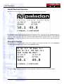
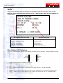
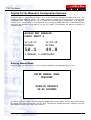
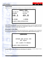
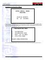
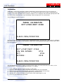
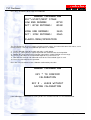
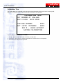
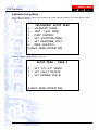
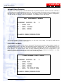
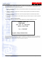
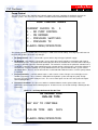
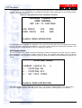
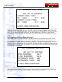
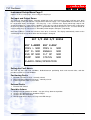
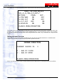
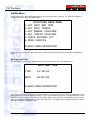
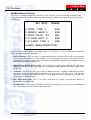
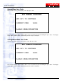
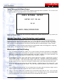
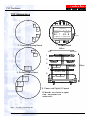
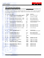
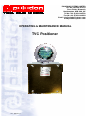
PALADON SYSTEMS LIMITED
VAT No. GB 336 4172 64
Ferro Fields, Brixworth
Northampton, NN6 9UA, UK
Tel No: +44 (0)1604 880700
Fax No: +44 (0)1604 882424
Email: [email protected]
www.paladonsystems.com
OPERATING & MAINTENANCE MANUAL
TVC Positioner
Doc: Q068 Rev 0
TVC Positioner
Contents
Contents.......................................................................................................................................................2
Features .......................................................................................................................................................3
Operation .....................................................................................................................................................4
First Time Operation ..................................................................................................................................4
Physical .....................................................................................................................................................4
Wiring.........................................................................................................................................................4
Normal Positioner Operation .....................................................................................................................5
Alternative Displays ...................................................................................................................................5
Faults .........................................................................................................................................................6
Main Display LED Indicators .....................................................................................................................6
Access To The Manual & Configuration Systems ...................................................................................7
Entering Manual Mode ..............................................................................................................................7
Manual Mode .............................................................................................................................................8
Returning To Auto Mode ...........................................................................................................................8
Entering Configuration Mode.....................................................................................................................9
Calibration................................................................................................................................................10
Calibration Trim .......................................................................................................................................12
Instrument Set-up Menu ..........................................................................................................................13
Solenoid Sense Selection....................................................................................................................14
Instrument Fail Mode ...........................................................................................................................14
Pump Control .......................................................................................................................................16
Pump Control .......................................................................................................................................16
Set Stepping Mode ..............................................................................................................................17
Set Deadzone and Band Edge Hysteresis ..........................................................................................18
Instrument Set-up Menu Page 2..............................................................................................................19
Set Input and Output Sense ................................................................................................................19
Setting the Fault Matrix ........................................................................................................................19
Setting Actuator Direction ....................................................................................................................20
Utilities Menu ...........................................................................................................................................21
Set Date and Time ...............................................................................................................................21
Set Miscellaneous Timers....................................................................................................................22
Manual Mode Pass Code ....................................................................................................................23
Configuration Mode Pass Code...........................................................................................................23
Force Retransmitted Signal Output .....................................................................................................24
Normal Operation - Fault Detection and Logging..................................................................................24
Maintenance and Fault-Finding ...............................................................................................................24
TVC Appearance .......................................................................................................................................26
Physical Description.................................................................................................................................27
Specification ............................................................................................................................................27
TVC Terminal Descriptions ......................................................................................................................28
Spares Kit Ordering & Additional Service Support ...............................................................................29
Doc : Q068 Rev 1
Page 2 of 29
TVC Positioner
Features
• Large backlit liquid crystal display
• Communication via infra red keypad
• Simple two-step calibration
• Calibration trim for fine adjustment
• 4-20mA current command signals and current or potentiometer feedback signal.
• Actual position 4-20ma calibrated output
• Three way isolation for command and actual position signals
• MANUAL mode
• Stepping mode with adjustable ON and OFF times
• Selectable solenoid drive sense for failsafe operation
• Selectable default operation on command signal/feedback signal break
• ESD solenoid output on fault - 24Vdc open drain
• Fault output - 24Vdc open drain
• Hydraulic pump drive controlled by demand or external pressure sensors
• External fault contact monitoring
• Selectable interlock between ESD and fault outputs
• Low power - normal operation less than 3W
• Direct mounting within Compact Ex d Enclosure System
The TVC can be used in any positioning system relying on the on-off control of the position driver including
electro-hydraulic actuators and reversing ac motors (with the addition of suitable relays or contactors). The
TVC can accept positional feedback from a three-wire potentiometer or a position transducer with a current
output. The TVC is mounted to a special chassis plate and fitted within an Exd enclosure. All field and
customer wiring is taken through a close-coupled Exe enclosure. Comprehensive power supply and signal
isolation allows connection to any user DCS system without the need for further signal isolation.
This handbook describes the configuration and operation of the basic TVC. Other hardware and firmware
options will be described in additional sections published separately.
Doc : Q068 Rev 1
Page 3 of 29
TVC Positioner
Operation
First Time Operation
Please read this handbook before operating the TVC. The instrument will have been set up during factory
trials so please avoid changing any parameters until you have gained some familiarity with the operation of
the positioner.
WARNING !!
The actuator and associated mechanical equipment connected to it could possibly move in an
unpredictable manner during initial calibration.
Ensure that all personnel take appropriate
precautions.
1.
Ensure that any end of travel limit switches and mechanical stops are correctly adjusted before
operation.
2.
Apply power and provide the 4-20mA command signal.
3.
Use the IR900 to enter Manual Mode.
4.
Operate the actuator in manual and confirm that the actuator moves as required.
5.
Return to automatic mode and confirm that the actuator follows the demand signal and that a suitable
actual position retransmitted signal is produced.
6.
At this stage, the accuracy of the calibration and the response of the system can be assessed and
recalibration and modification to the control parameters can be considered.
The instrument compares two analogue signals, one representing the desired position (command signal) and
the other representing the actual position (feedback signal) of the actuator.
A difference between these two signals will cause one of the TVC outputs to operate, driving the actuator to
the desired position.
A positional dead-zone may be adjusted to overcome “hunting” problems associated with mechanical overrun
of the actuator and further band edge hysteresis adjustments refine this setting.
The speed of transit of the actuator can be reduced by selecting the stepping mode that provides
independently adjustable on and off times for the open and close solenoid operation.
Physical
The TVC is mounted on a chassis plate and housed within an Exd enclosure. The circuit boards are coated
with a resist layer that protects the track from moderate condensation and mould growth problems.
Connections within the EXd enclosure are by factory assembled 0.1” connectors and must not be disturbed or
re-wired. The only internal hardware configuration adjustment is the jumper link selection of either sinking or
sourcing excitation of the retransmitted actual position signal and is usually set to customer requirements on
order. The TVC requires the Intrinsically Safe (Exia’) IR900 keypad for calibration, configuration and manual
operation.
Wiring
Wiring to the Exe enclosure terminals should be completed by suitably trained personnel taking into account
the following notes:
• To ensure RFI compliance the analogue signals should be routed in copper braided screened cables with
a fill factor density of at least 0.7.
• The screens should be terminated to the metal of the actuator housing, ideally at a suitable metal cable
gland.
• Signal cables should be routed separately from power and switching conductors.
Doc : Q068 Rev 1
Page 4 of 29
TVC Positioner
Normal Positioner Operation
When the TVC is first switched on the display will show the normal running status:
The Paladon Systems logo is displayed over the first three lines. The first text line shows the time as
hrs:mins:secs (24 hour clock) followed by the date as dd:mm:yy. The main display shows the current demand
signal as a percentage of the full range, normally 4-20mA followed by the actuator stroke as a percentage of
the full stroke. In normal operation the display will reflect changes in the demand signal and the position of
the actuator.
Alternative Displays
Pressing key * on the IR900 keypad removes the Paladon Systems logo and displays the current dead zone
and band edge hysteresis data and the current fail-mode setting:
The display toggles back to the Paladon Systems logo with a further press of the * key on the IR900.
Doc : Q068 Rev 1
Page 5 of 29
TVC Positioner
Faults
In the event of a positioning fault, the first three lines will detail the fault and the response of the actuator.
Note: The failed system information will be reset to a normal display when the fault condition has
been resolved.
Descriptions Line Can Include
Positioner Fault Line
LOSS OF DEMAND SIGNAL
FAILED CLOSE
LOSS OF F/B SIGNAL
FAILED OPEN
FAILURE TO POSITION
FAILED STAY PUT
EXTERNAL FAULT INPUT
GO TO POSN. ON FAULT
Main Display LED Indicators
There are 8 LED indicators above the main display and they have the functions, running clockwise from top
right:
1.
2.
3.
4.
5.
6.
7.
8.
CLOSE
8
1
OPEN
FAULT
7
2
MANUAL
ENABLED
6
3
STEP
5
4
ESD
OPEN – lit when the open solenoid is energised
MANUAL – lit when the TVC is in manual mode
STEP – lit when stepping mode has been selected
ESD – lit when the ESD output is energised – this may be ‘fail-safe i.e. energised healthy
Future use
ENABLED – lit when the enable contact has been made, enabling access to manual and configuration
FAULT – lit when there is a fault within the TVC system– this may be ‘fail-safe i.e. energised healthy
CLOSE – lit when the close solenoid is energised
Doc : Q068 Rev 1
Page 6 of 29
TVC Positioner
Access To The Manual & Configuration Systems
An external volt free contact closure enables access to the manual and configuration modes of the TCV. The
contact should be MADE to enable. The contact switches a 24Vdc input excited from the common bulk
supply to the TVC. LED 6 is lit if the TVC is enabled for manual operation or configuration. If an attempt is
made to access manual (Key 1) or configuration (Key 2) using the IR900 without the enable contact being
made then the following display will be seen for 10 seconds. The positioner will continue to operate in
automatic mode:
!
"
#
$
Entering Manual Mode
If the TVC input 4 is made and Key 1 is pressed on the IR900 then the following display is seen:
#
#
$
%
If a correct 4-digit pass code is not entered by the IR900 within the time shown, then the display will revert to
the normal auto mode when the timer reaches zero. Note that the actuator will remain stationary at the last
auto position during the pass code entry sequence.
Doc : Q068 Rev 1
Page 7 of 29
TVC Positioner
Manual Mode
After a successful pass code entry the following screen is displayed and LED 2 is illuminated:
&
& #
!
Keys 1 and 2 on the IR900 control the opening and closing of the actuator. The actual solenoids operated will
depend on the Solenoid Sense setting for the particular hydraulic circuit used in the actuator. All system
fault monitoring is disabled in manual mode thus enabling further diagnostics of a known faulty system.
Pressing the # key starts the exit routine from manual mode.
Returning To Auto Mode
Pressing the # key does not immediately switch operation to auto. An intermediate screen is displayed to
warn if the actual position deviates more than the current dead zone setting from the current demand signal.
This protection will protect the process from a step change in flow and allow a smooth transfer to auto.
'
"
#
!
Key 1 will return to manual mode and key # will show the auto mode display. LED will extinguish and the
positioner will go into automatic operation with fault monitoring re-established.
Doc : Q068 Rev 1
Page 8 of 29
TVC Positioner
Entering Configuration Mode
#
$!
#
%
$
$
$
If the TVC is not enabled then the same warning message, as described for manual mode entry above, will be
shown. If enabled, automatic positioning is suspended and the actuator is left in its stay put position, and the
pass code entry display, above, will be shown. Entry of the correct pass code within the time indicated will
allow entry to the main configuration menu.
$
$
!
$
!
Key 1 to 4 selects one of the options shown and key # returns the display and operation to automatic mode.
Doc : Q068 Rev 1
Page 9 of 29
TVC Positioner
Calibration
Calibration is a two-stage procedure requiring control of the demand signal to the TVC and a means of
measuring the retransmitted signal from the unit. The actuator and valve may need to be isolated from the
process as full stroke operation of the actuator is required. It is usually best if the demand signal injection and
the actual retransmitted position signal monitoring is done locally to the TVC and actuator.
Select Calibration by pressing key 1
"
!
* +
()
!
Pressing key # will return the display to the Configuration Menu. Pressing key * will start the calibration
procedure at the ‘low end’ i.e. the actuator stroke to be associated with the 4mA demand signal, (often
the closed position.)
!
#& $
(
'
$
$
!
The descriptions are in reverse contrast and the numeric values, the internal bit conversion values, are in
normal contrast. The low end calibration procedure is as follows:
1.
2.
3.
4.
5.
6.
Set the demand signal to the low end value, usually 4mA.
Use Key 1 (close) or Key 2 (open) to position the actuator to the desired position.
Monitor the retransmitted actual position signal with a suitable DVM on current range.
Use Key 4 to reduce the retransmitted output or Key 5 to increase it.
Note that the last low end calibrated value for the retransmitted signal is used.
Press Key # to complete the operation.
Doc : Q068 Rev 1
Page 10 of 29
TVC Positioner
Press Key * to continue to the ‘high end’ calibration
#& $
(
'
!
$
$
)
)
*
$
*
!
The descriptions are in reverse contrast and the numeric values, the internal bit conversion values, are in
normal contrast. The high end calibration procedure is as follows:
7.
8.
9.
10.
11.
12.
Set the demand signal to the high end value, usually 20mA.
Use Key 1 (close) or Key 2 (open) to position the actuator to the desired position.
Monitor the retransmitted actual position signal with a suitable DVM on current range.
Use Key 4 to reduce the retransmitted output or Key 5 to increase it.
Note that the last high end calibrated value for the retransmitted signal is used.
Press Key # to complete the operation.
Press the * Key to continue to the calibration confirmation procedure.
!
# &
#
$ %
%
(
)
If the calibration is confirmed then scaling factors are calculated and all are saved to EEPROM.
Doc : Q068 Rev 1
Page 11 of 29
TVC Positioner
Calibration Trim
This facility allows the calibration at the low demand end (normally valve closed) to be finely adjusted,
typically for seating of valves, without having to go through a full calibration.
!
$
(
#
$
#
+
!
(
$
#
$ %
%
(
)
The trim adjustment procedure is as follows:
1. Set the demand signal to the low end value, usually 4mA.
2. Use Key 1 (close) or Key 2 (open) to position the actuator to the desired position.
3. Press Key # to complete the operation.
Doc : Q068 Rev 1
Page 12 of 29
TVC Positioner
Instrument Set-up Menu
These sub-menu allow the set up of the positioner to suit the hydraulic hardware, the control signals and the
process control required.
#
$
$
$
$
!
$
$
*
!
$
!!
,
-)#$
$
)
!
A further selection appears if Key 6 is pressed:
#
$
$
$
!-
& #
! $
$
'
.
!
Doc : Q068 Rev 1
Page 13 of 29
TVC Positioner
Solenoid Sense Selection
This allows the matching of the solenoid control with the particular hydraulic circuit used and is normally a
one-off adjustment completed during factory tests. The open and closed solenoids can be assigned to cause
flow either when energised or when de-energised. This allows the three common hydraulic configurations,
stay put, fail close or fail open, under fault conditions. The following screen is displayed:
$
)
# !
$
$
!
!
The current selection is shown and pressing Keys 1-3 will select a new setting. Pressing Key # will return to
the main Set up Menu and save any changes.
Instrument Fail Mode
The TVC can detect failures in the systems connected. The demand or actual position feedback signals are
monitored and an alarm is set if they stray outside the normal 4-20mA range – the detection points are less
than 1mA or greater than 21mA. The time taken to position is monitored and an alarm set if position has not
been attained. An external contact input, possibly monitoring hydraulic pressure unit operation is also
monitored. Any or all of these points can cause the positioner to fail to a predetermined position – see Fault
Matrix Selection below for further details. This menu sets the fail position:
#
$
)
# !
$
$
!
! $
!
Doc : Q068 Rev 1
Page 14 of 29
TVC Positioner
The current selection is shown and pressing Keys 1-4 will select a new setting. Pressing Key # will return to
the main Set up Menu and save any changes. In most cases, the fail mode will be associated with the state
of the hydraulic flow with the solenoids de-energised.
1. Stay put – normal for a double acting system where both solenoids are de-energised when the actuator is
at the required position.
2. Fail close – normal for an actuator with a mechanical spring or hydraulic accumulator to close with the
solenoids de-energised.
3. Fail open – normal for an actuator with a mechanical spring or hydraulic accumulator to open with the
solenoids de-energised.
4. Fail to position would normally be used on a double acting system where the process required a particular
fail position.
Choice 4 - Fail To Position
The final choice requires the setting of the stroke position that the actuator would drive to on fault.
#
#
#
! $
!
!
The current fail position is displayed. Pressing any key will place a flashing cursor on the value, waiting for a
position to be entered in the range 00.0 to 99.9%. The value can be changed by repeating the process and
the operation can be finished and the valued saved by pressing Key #
Doc : Q068 Rev 1
Page 15 of 29
TVC Positioner
Pump Control
The TVC can oversee the control of the hydraulic power unit pump supplying the hydraulic circuit to the
actuator system. This menu lists the choices available for that control and the associated settings.
#
#
)
! !
!
!
$$
$$
$
$(
'
) $
!
The current selection is shown and pressing Keys 1-4 will select a new setting. Pressing Key # will return to
the main Set up Menu and save any changes.
1. No Pump Control – this is selected for systems with a ring-main type hydraulic supply.
2. On Demand – this would be selected for systems with some local hydraulic accumulation and a low to
moderate duty cycle. The pump would start to operate when the actuator was caused to move either by a
change in demand signal or in manual operation. The control is sensitive to the particular solenoid sense
set for the system thus the pump would not run for actuator closing if fail close was selected or fail open if
fail open was selected. Similarly, the pump would not run if the system had detected a system fault as
described above. There is also an overrun time associated with mode that can be set if this pump control
is selected.
3. Pressure Switches – external contact inputs 1 and 2 can be used as low pressure and high pressure
controls respectively. These switches, fitted within the hydraulic system, will stop the pump at high
pressure and start it again at low pressure. The sense of the inputs can be set in the Input and Output
Sense Setting below.
4. Pressure Transmitter – the pressure switches mentioned above can be replaced with a pressure
transmitter, connected to Internal Analog Input 2. A further menu sets the low and high switching for this
transmitter.
Choice 2 – Set Pump On Demand Run On Time
#
#
$
$
&
#
#
!
Doc : Q068 Rev 1
Page 16 of 29
TVC Positioner
The current run on time is displayed. Press any key to start and enter the required time in the range 0 to 999
seconds. The entry can be changed by repeating the procedure and the operation can be finished and the
values saved by pressing Key #.
Choice 4 – Pump Control Pressure Transmitter Set Points
#
#
#
#
#
( ! $$
) ) ! $$
!
The current pressure set points are displayed. Press any key to start and enter the required low and high
pressure set points in the range 0 to 999 Bar. The entries can be changed by repeating the procedure and
the operation can be finished and the values saved by pressing Key #.
Set Stepping Mode
The TVC can operate its control solenoids intermittently in order to slow down the actuator speed in situations
where the process cannot tolerate sudden changes in flow. This stepping mode applies preset on and off
times to both the close and open solenoids, giving the option for different speed operation for opening and
closing.
##
)
$
$
$
!!
!!
$
$
!
$
!
The current stepping mode is displayed. Press Keys 1-3 to select the required option. Pressing the # Key
saves the selection and returns the display to the main Set up Menu. Selecting 3 opens a new menu:
Doc : Q068 Rev 1
Page 17 of 29
TVC Positioner
#
#
#
!
+$
$
* /
$
$
+$
* /
!
The current on and off times are shown. Pressing any key (other than #) sets a flashing cursor on the OPEN
TIME – ON selection and further key presses will enter a value in the range 0 to 999mS. Pressing any key
(other than #) then selects the OPEN TIME – OFF and further key presses will enter a value in the range 0 to
999s – note the different units from the ON time. The OFF TIMES can be selected in a similar manner.
Repeated pressing of the # Key will skip other entries and return the display to the Set up Menu, saving any
changes.
Set Deadzone and Band Edge Hysteresis
The deadzone allows an area of control of the actuator position where no movement takes place. Such a
zone is required in systems that have on-off control of the hydraulic control elements due to magnetic and
mechanical delays inevitable with such components. Control is enhanced by having two settings, one for the
open direction and one for the close direction solenoid operations. The hysteresis value provides an
additional suppressed band, active only on entry into the deadzone to reduce instability due to conversion and
arithmetical errors in the positioner. The deadzone is expressed in percent of full stroke of the actuator whilst
the hysteresis is a notional value.
#
!
$
)#$
)#$
#
,
,
$ $ !
$ $
$
*
!
The current deadzone and hysteresis values are shown. Pressing any key (other than #) sets a flashing
cursor on the first value, which can then be changed. Subsequent presses of the # Key pass through each
value without change and , eventually, the display returns to the main Set up Menu.
Doc : Q068 Rev 1
Page 18 of 29
TVC Positioner
Instrument Set-up Menu Page 2
Options are on a second page, accessed by pressing Key 6
Set Input and Output Sense
The TVC has four digital inputs, internally pulled high to the 24V instrument supply and four open drain
outputs acting as low-side switches using the 24V instrument supply. This setpoint allows the inactive state to
be set for both inputs and outputs. Pressing Key 1 sets a normal state, inputs pulled high, outputs not
energised, and Key 2 set the reverse condition. If Key # is pressed the display will return to the second page
of the Set up Menu, otherwise the key press is ignored but subsequent Key presses of 1, to select normal, or
2 (or any other key), to select reverse, will modify all four outputs and inputs sequentially.
Note that if editing is started then all values have to be re-entered. The display automatically returns to the
second page of the Set up Menu when the final output is changed.
*#
"
)
! $
'
$
!
! !
*#
"
!
)
$ )
$
!
$
%
!
Setting the Fault Matrix
The TVC has four main fault conditions, divided between positioning faults and external faults, and four
possible reactions to a fault condition:
Positioning Faults
1. Demand signal out of range – normally a break
2. Actual position feedback out of range – normally a break
3. Failure to position within a preset time
External Faults
1. External fault contact
Possible Actions
1.
2.
3.
4.
Change actuator position or control – stay put, fail up, down or to position
Change state of Emergency Shutdown Output
Change state of Fault Output
Alert operator with a display message and LED changes
Doc : Q068 Rev 1
Page 19 of 29
TVC Positioner
This option can associate Positioning Faults and External Faults with any of these four actions.
+
$
-
- '
! $
! $.
$
$!
&
'
!
!
#
!
The matrix can be inspected without change by just pressing the # Key to exit to the second page of the Set
up Menu. Keys 1-4 select the positioner action, followed by Keys 1 or 2 to change the choice. The selections
for Positioner and External Faults have to be completed for each action. Key * terminates the entry for each
choice.
Setting Actuator Direction
The positioner needs to know what solenoid operates to move the actuator towards the set 4mA demand
signal, as it is possible to set the fully open position equivalent to 4mA.
)
+
+
$
$
!
!
Keys 1 or 2 will change the choice and Key # will return the display to the second page of the Set up Menu.
Doc : Q068 Rev 1
Page 20 of 29
TVC Positioner
Utilities Menu
The final item in the Main Configuration Menu is the Instrument Utilities Settings. Pressing Key 4 from the
Configuration Menu enters the Utilities Menu.
$
$
$
$
*
$
)
$
! $$
! $$
$
!
$
!
Pressing Keys 1-6 will access the listed choices and Key # will return the display to the Main Configuration
Manu.
Set Date and Time
The TVC has a real time clock equipped with a short term back up in the event of power loss.
!
Pressing Key # returns the display to the Utilities Menu. Pressing any other key starts the editing process by
placing a flashing cursor on the hours display. Key in the required time, hh:mm, as prompted by the cursor.
A further press of the # key will return to the Utilities Menu, leaving the date unchanged, but pressing any
other key will start the editing process of the date, dd:mm:yy. The display returns automatically to the Utilities
Menu on completion of editing the date.
Doc : Q068 Rev 1
Page 21 of 29
TVC Positioner
Set Miscellaneous Timers
The TVC has a number of utility timers that can be reset if desired. These are normally set during factory
testing and should only be adjusted after fully understanding the function of the timer and any consequences
of the change.
! $
!
.
(
! $
(
)
$
$
$
$
$
!
Pressing Key # returns the display to the Utilities Menu. Pressing Keys 1-5 selects the timer to be edited and
places a flashing cursor on the first digit.
1. Time To Position – this is the time in seconds allowed for the actuator to move to the desired position
before a positioning fault is set. This should be set to at least 50% more than the full stroke time of the
actuator to avoid spurious alarms. This timer will be suspended if the positioner is in stepping mode due
to the very long potential stroking times.
2. Operator Entry Enable Warning Time – this is the time in seconds that a warning will show on the
display if an attempt is made to enter Manual or Configuration modes without the external enable contact
being made.
3. Trim Pulse – this is the ‘on’ time pulse length, in 100mS increments. During the Calibration operation it
may be necessary to finely position the actuator using the key pad. This timer sets a short ON pulse
followed by 5 times the pulse time OFF pulse. The resulting pulse train can position the actuator more
precisely than a continuous pulse.
4. Pass Code Entry Timer – this is the down count timer in seconds associated with Manual or
Configuration pass code entry.
5. Backlight Timer – The display backlight is normally off but will light on any key press from IR900 key
pad. The display will stay lit for the duration of this timer.
Doc : Q068 Rev 1
Page 22 of 29
TVC Positioner
Manual Mode Pass Code
Manual Mode entry is protected by a four digit pass code.
#
#
#
!
Press Key # to return to the Utilities Menu. Press any other key to start editing the pass code. The display
returns to the Utilities Menu automatically after the entry is complete.
Configuration Mode Pass Code
Configuration Mode entry is protected by a four digit pass code.
#
#
#
!
Press Key # to return to the Utilities Menu. Press any other key to start editing the pass code. The display
returns to the Utilities Menu automatically after the entry is complete.
Doc : Q068 Rev 1
Page 23 of 29
TVC Positioner
Force Retransmitted Signal Output
This option is included to acts as a check for the outgoing signal loop from the positioner. This can be useful
in checking problems in the signal interface on the process DSC.
#
!
+
!
Entering a value in mA will cause that current to be output by the suitably calibrated TVC. Key # returns the
display to the Utilities Menu.
Normal Operation - Fault Detection and Logging
In normal operation the TVC positioner will cause the actuator to position to the demand signal within the
dead zone set and output an actual position signal. The system will detect faults in demand and feedback
signals and changes to the external fault input and take preset actions in event of these faults. None of the
fault conditions are latched within the TVC and any fault action will clear automatically the fault is rectified.
Any faults, power up events and entry into the Manual or Configuration modes will be logged in a simple log
of 255 events. The log can be inspected in the Utilities Menu
Maintenance and Fault-Finding
1. The vast majority of first time use failures are a result of incorrect electrical connections or compatibility
problems in control signals. Remember, the positioner and actuator system will have been tested before
shipment, so double-check all electrical connections and signal excitation sense against drawings and
descriptions specific to the particular installation before any power is applied.
2. In fault-finding the system, always work from the known towards the unknown. Operating the system in
Manual Mode confirms a large part of the system as being ok – hydraulics, power to the positioner,
general TVC operation. If the manual mode display shows correct variations of the demand and actual
position signals then these signals are also proved, similarly for the retransmitted actual position signal.
3. At the most basic level, disconnect the actuator solenoids – ALWAYS with the TVC power OFF – and
operate the solenoids directly with 24Vdc. This will isolate hydraulic problems from electrical control
ones.
4. The current loops in and out of the TVC are isolated from each other and the instrument supply so there
will be no problems with crossed grounds and no need for external isolators.
5. There is a need to check on the excitation of the retransmitted signal form the TVC. This is the only
hardware adjustment on the instrument and comprises of a set of jumper links on the third board down
from the display board. The instrument will have to be removed from the enclosure:
Doc : Q068 Rev 1
Page 24 of 29
TVC Positioner
a) Unscrew the two captive fixings at the top and bottom of the instrument.
b) Carefully pull out the instrument part-way until the jumper links are visible on the lower edge of the
board
c) From the left, the link positions are
Sourcing, 1 and 3 excitation from the TVC
Sinking, 2 and 4 excitation from the external DSC
d) Replace the TVC in the enclosure before re-applying power.
6. Problems in instability and precision of positioning can be address by adjustment of the dead zone and
hysteresis bands or, more directly, by adjusting the speed of the actuator via hydraulic flow regulation.
Positional overshoot is caused by a failure of the control solenoids to act quickly enough to stop the
actuator where required. Slowing down the actuator stroke speed is the ONLY way of improving
positional accuracy.
7. Reversed demand signal loops or incorrect connection of external fault devices can cause a failure to
operate in automatic mode when there is, apparently, no fault seen in manual mode. Check the fault
display, input and output sense setting and the fault matrix setting against the required fault environment.
8. In the event of ‘losing’ the manual and configuration mode pass codes, there is a back door.
a) Set the demand signal to 0mA, or temporarily disconnect
b) Enter the Configuration Mode and use the pass code 8765
c) Go to the Utilities Menu and reset the pass code as required.
d) Reconnect and reset the demand signal
9. The TVC is not user serviceable. In the event of suspected failure:
a) check all the advice above to eliminate external system faults
b) produce a full a failure report as possible, with times, dates, photographs, logs etc – anything to help
us to understand the environment surrounding the failure
c) carefully remove the TVC from the EX2010 housing and unplug the free sockets
d) package the unit in anti-static bubble wrap and a good solid outer box and return to the supplier
Doc : Q068 Rev 1
Page 25 of 29
TVC Positioner
TVC Appearance
LEDs
IrDA
789
IR
C
10 11 12
Company Logo
D
12: 34: 27
DEMAND
50. 1
A
123
12: 12: 10
ACT UAL
49. 8
SD CARD
1 - MANUAL 2 - CONF I GURE
B
456
RS232
2. Processor/Analog Board
F
80o/a
1
C
3. Analog Output Board
22
21
20
19
5
A
D
F
4
4 SINK
2 SINK
3 SOURCE
1 SOURCE
3
23
24
25
26
BOTTOM
TOP
13
14
15
2
30
29
28
27
USB
1. Display Board
16
17
18
E
LEDs
B
links
E
Comms Board
not always fitted
I
H
G
I
H
G
5. Power and Digital I/O board
All boards are shown in upper
view - connectors are
underneath
Note – elevation is rotated by 90°
Doc : Q068 Rev 1
Page 26 of 29
85o/a
TVC Positioner
Physical Description
Size with chassis plate – 80mm wide, 80mm high, 85mm deep
Weight with chassis plate – 0.25kg
Specification
COMMAND SIGNAL INPUT
4-20mA
nominal 160R input impedance, fully isolated
ANALOGUE POSITION OUTPUT SIGNAL
0.5-22mA
can be calibrated anywhere in this range , normally 4-20mA, fully isolated
Sourcing – 750R load, Sinking – max excitation 30V
FEEDBACK SIGNAL INPUT
Potentiometer 3-wire, any value greater than 200R
4-20mA
nominal 160R input impedance – signal common with instrument supply
SOLENOID OUTPUTS x 2
Maximum 2A for each output PWM with 12 bit resolution, 24Vdc common with instrument supply
SWITCHED OUTPUTS x 4
Maximum 1A for each output – low side switched 24Vdc common with instrument supply
CONTACT CLOSURE INPUTS X 4
Internally pulled high to instrument power supply.
INSTRUMENT AND SOLENOID SUPPLY
24V dc nominal (15-28V absolute maximum range) – 2.8W excluding solenoids
100mA
maximum current drawn in normal use
USER ADJUSTMENTS
All adjustments via IR900 Infra Red Keypad
INTERNAL LINKS
Retransmitted actual position excitation
Link 1 and 3 – sourcing, internal excitation from isolated 24Vdc supply
Link 2 and 4 – sinking external excitation, maximum 30Vdc
ENVIRONMENT
Operating temperature -40ºC to +59ºC ambient
Storage temperature
-40ºC to +115ºC
PERFORMANCE - the following applies to the TVC only, characteristics of the feedback element and
actuator system response will have additional effects.
Conversion
12 bit max normal conversion range (4-20mA) = 1 in 4000.
O/P switch res.
+/-1 bit theoretically, modified to up to +/-5% of span by dead band .
Doc : Q068 Rev 1
Page 27 of 29
TVC Positioner
TVC Terminal Descriptions
Note – Always use specific drawings and hook-up diagrams supplied with the job for site wiring. The
descriptions below are for information only.
Connections are made via up to nine 3 and 4 way polarised 0.1” free sockets. The free sockets are marked A
to I as are the printed circuit board pin headers. Double check all connections when removing or replacing
the TVC from the enclosure.
No.
1
2
3
Conn.
A
A
A
Description
24V dc instrument supply, feedback excitation
Feedback signal +ve – 4-20mA into 160R
Feedback signal –ve – instrument 0V
Voltage
24Vdc
3.2V
0V
Common inst. Supply
4
5
6
B
B
B
Uncommitted analog internal input 4 – 160R
Uncommitted analog internal input 3 – 160R
Pressure TX +ve – 4-20mA into 160R
3.2V
3.2V
3.2V
Not usually connected
Not usually connected
For pump control and P.S.
7
8
9
C
C
C
External analog inputs EMC ground
Demand signal +ve – 4-20mA into 160R
Demand signal -ve
0V
3.2V
0V
Connect to good signal ground
Isolated analog input
10
11
12
D
D
D
Uncommitted analog isolated input 1 – 160R
Uncommitted analog isolated input 2 – 160R
Uncommitted analog isolated input 3 – 160R
3.2V
3.2V
3.2V
Not normally connected
Not normally connected
Not normally connected
13
E
Retrans. actual position signal +ve 4-20mA
24V
Can be sinking or
14
15
E
E
sourcing
Retrans. actual position signal –ve
Retrans. Signal EMC ground
3.2V
0V
Isolated output
Connect to good signal ground
16
17
18
F
F
F
Foundation Fieldbus data +ve
Foundation Fieldbus data -ve
Fieldbus Signal EMC ground
3.3V
3.3V
0V
Not usually connected
Not usually connected
Connect to good signal ground
19
20
21
22
G
G
G
G
Instrument and solenoid supply +ve
Instrument and solenoid supply –ve
Close solenoid –ve switched
Open Solenoid –ve switched
24Vdc
0V
24Vdc
24Vdc
Solenoid +ve to +24V
Solenoid +ve to +24V
23
24
25
26
H
H
H
H
ESD solenoid output –ve switched
Fault output –ve switched
Pump control output –ve switched
Remote status output –ve switched
24Vdc
24Vdc
24Vdc
24Vdc
Output +ve to +24Vdc
Output +ve to +24Vdc
Output +ve to +24Vdc
Output +ve to +24Vdc
27
28
29
30
I
I
I
I
Pump control low press switch +ve
Pump control high press switch +ve
External fault input +ve
Operator enable input +ve
24Vdc
24Vdc
24Vdc
24Vdc
Switch to inst. 0V
Switch to inst. 0V
Switch to inst. 0V
Switch to inst. 0V
Doc : Q068 Rev 1
Comment
Not usually connected
Page 28 of 29
TVC Positioner
Spares Kit Ordering & Additional Service Support
When requesting service support or ordering spares kits, please provide the following contract details:
•
•
•
•
•
Actuator Serial Number (6 or 7 digit number with a RFPL prefix)
Paladon Contract Number (5 digit number with an ACCP, ACE, ACP, ACSP, CCP, CE, CGH, CP, CPC or
CSP prefix)
General Arrangement or Control Schematic Drawing Number
Full Actuator Model Number(s) and Descriptions
Tag Number(s)
Please contact your nearest Paladon representative as detailed below:
•
Paladon Systems Ltd
Ferro Fields, Brixworth, Northampton, NN6 9UA, England
Tel: +44 (0)1604 880700 Fax: +44 (0)1604 882424
[email protected]
•
Paladon Systems Ltd
Howemoss Drive, Kirkhill Industrial Estate, Dyce, Aberdeen,
AB21 0GL, Scotland
Tel: +44 (0)1224 772442 Fax: +44 (0)1224 772868
[email protected]
•
Paladon Italia
Via Barbieri, 24, 27040 Pinarolo Po, PV, Italy
Tel: +39 0383 878524 Fax: +39 0383 878042
[email protected]
•
Paladon SDT
121352 Davydkovskaya Str. 12/3. Moscow, The Russian Federation
Tel/Fax: +7 495 735 28 07 (08) (09)
[email protected]
•
Paladon Systems Ltd
Asia Pacific Region
Lot 3-4, Jalan Tanjung Keramat 26/35, Seksyen 26,
40400 Shah Alam, Selangor, Malaysia
Tel: +603 5102 5063 Fax: +603 5102 5100 Mobile: +6012 311 3247
[email protected]
•
www.paladonsystems.com
Doc : Q068 Rev 1
Page 29 of 29