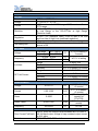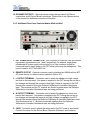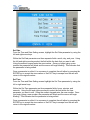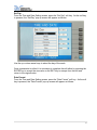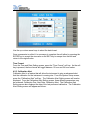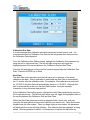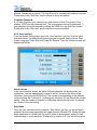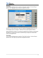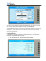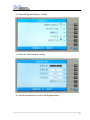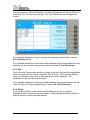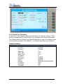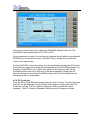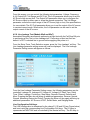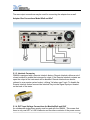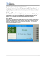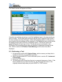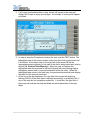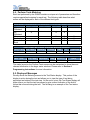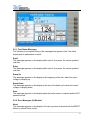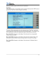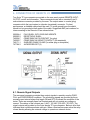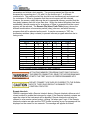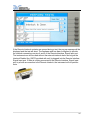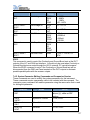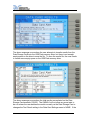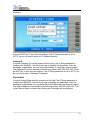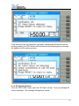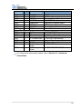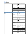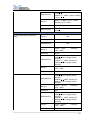
1
OPERATION AND SERVICE MANUAL OMNIA II models 8204/8254 OMNIA II models 8206/8256 OMNIA II models 8207/8257 Electrical Safety Compliance Analyzer AC/DC HIPOT WITH INSULATION RESISTANCE TESTER, GROUND BOND, AND CONTINUITY TESTER 825x INCLUDES 500VA OUTPUT CAPABILITY 82x6 INCLUDES RUN TEST AND LINE LEAKAGE TEST 82x7 INCLUDES 500VA AC POWER SOURCE SERIAL NUMBER Models 8204/8254/8206/8256 8207/8257 Item 39334 Ver 3.11 © Associated Research, Inc. 2013 13860 West Laurel Drive Lake Forest, Illinois, 60045-4546 U.S.A. Printed June 26, 2013 DECLARATION OF CONFORMITY Manufacturer: Associated Research, Inc. Address: 13860 W. Laurel Dr. Lake Forest, IL 60045 USA Product Name: OMNIA II® Electrical Safety Compliance Analyzer Model Number: 8204/8254/8206/8256/8207/8257 Conforms to the following Standards: Safety: EN 61010-1:2001 EN 61010-031:2002+A1:2008 EMC: EN 61326-1:2006 Class A EN 61000-3-3:2008 EN 61326-1:2006 (industrial locations) IEC 61000-4-2:2008 IEC 61000-4-3:2006+A1:2007+A2:2010 IEC 61000-4-4:2004+A1:2010 IEC 61000-4-5:2005 IEC 61000-4-6:2008 IEC 61000-4-8:2009 IEC 61000:4-11:2004 Supplementary Information The product herewith complies with the requirements of the Low Voltage Directive 2006/95/EC and the EMC Directive 2004/108/EC. The CE marking has been affixed on the device according to article 10 of the EMC Directive 8/336/EEC. The technical file and other documentation are on file with Associated Research, Inc. ______________________________ Joseph Guerriero Vice President / General Manager Associated Research, Inc. Lake Forest, Illinois USA June 29, 2012 TABLE OF CONTENTS 1. INTRODUCTION .............................................................................................. 1 1.1. Warranty Policies ....................................................................................... 1 1.2. Safety Symbols .......................................................................................... 3 1.2.1. Product Marking Symbols ................................................................ 3 1.2.2. Caution and Warning Symbols ........................................................ 3 1.3. Glossary of Terms ..................................................................................... 3 1.4. Safety .......................................................................................................... 5 1.4.1. Service and Maintenance ................................................................ 5 1.4.2. Test Operator .................................................................................... 6 1.5. Key Features of OMNIA II......................................................................... 8 2. GETTING STARTED ........................................................................................ 9 2.1. Unpacking and Inspection ........................................................................ 9 2.1.1. Packaging .......................................................................................... 9 2.1.2. Contents of the Carton ..................................................................... 9 2.1.3. Returning the Instrument for Service or Calibration .................... 10 2.2. Installation ................................................................................................ 11 2.2.1. Work Area........................................................................................ 11 2.2.2. Power Requirements ...................................................................... 11 2.2.3. Basic Connections .......................................................................... 11 2.2.4. Environmental Conditions .............................................................. 12 3. SPECIFICATIONS AND CONTROLS ............................................................ 13 3.1. OMNIA II Functional Specifications ....................................................... 13 3.2. Instrument Controls ................................................................................. 25 3.2.1. Front Panel Controls ...................................................................... 25 3.2.2. Rear Panel Controls ....................................................................... 27 3.2.3. Additional Rear Panel Controls ..................................................... 28 4. PROGRAMMING INSTRUCTIONS ................................................................ 30 4.1. Power Up .................................................................................................. 30 4.2. Setup System ........................................................................................... 30 4.2.1. Setup System Keys ........................................................................ 31 4.2.2. Time and Date ................................................................................ 31 4.2.3. Calibration Alert .............................................................................. 34 4.2.4. Hardware ......................................................................................... 36 4.2.5. Security ............................................................................................ 39 4.2.6. Power-On Screen ........................................................................... 48 4.3. Setup Tests Menu ................................................................................... 50 4.3.1. TVB-2 Default Test File.................................................................. 51 4.3.2. Add ................................................................................................... 51 4.3.3. Edit ................................................................................................... 52 4.3.4. Delete............................................................................................... 52 i 4.3.5. Prompt ............................................................................................. 53 4.3.6. File ................................................................................................... 54 4.3.7. Fail Stop........................................................................................... 55 4.4. Test Parameters ...................................................................................... 56 4.4.1. Description of Test Parameters ..................................................... 56 4.4.2. Default Parameters......................................................................... 60 4.5. Setting Up a Test ..................................................................................... 63 4.5.1. AC Withstand .................................................................................. 66 4.5.2. DC Withstand .................................................................................. 67 4.5.3. Insulation Resistance ..................................................................... 69 4.5.4. Continuity......................................................................................... 70 4.5.5. AC Ground Bond ............................................................................ 70 4.5.6. Continuity......................................................................................... 72 4.5.7. Functional Run Test (Model 82x6 and 82x7) ............................... 73 4.5.8. Line Leakage Test (Models 82x6 and 82x7) ................................ 76 4.6. Setting Up a Test ..................................................................................... 86 5. OPERATING INSTRUCTIONS ....................................................................... 88 5.1. Instrument Connections .......................................................................... 88 5.1.1. Connecting the Test Leads............................................................ 88 5.1.2. Adapter Box Connections .............................................................. 88 5.1.3. Interlock Connector ........................................................................ 89 5.1.4. DUT Input Voltage Connections for Models 82x6 and 82x7 ...... 89 5.1.5. Scanner Connections ..................................................................... 90 5.2. Perform Tests Menu ................................................................................ 91 5.2.1. Load File .......................................................................................... 91 5.2.2. Single Step ...................................................................................... 92 5.2.3. Fail Stop........................................................................................... 92 5.2.4. Results ............................................................................................. 93 5.3. Performing a Test .................................................................................... 94 5.4. Perform Tests Metering........................................................................... 96 5.5. Displayed Messages ............................................................................... 96 5.5.1. Test Status Messages (all Models) ............................................... 97 5.5.2. Error Messages (All Models) ......................................................... 99 5.5.3. Error Messages (Models 82x6 and 82x7) .................................... 99 6. CONNECTION OF REMOTE I/O .................................................................. 102 6.1. Remote Signal Outputs ......................................................................... 102 6.2. Remote Signal Inputs and Memory Access ........................................ 103 7. BUS REMOTE INTERFACE USB / GPIB / RS-232 ..................................... 106 7.1. USB/RS-232 Interface........................................................................... 106 7.1.1. RS-232 Connector ........................................................................ 106 7.1.2. Communications Port Configuration ........................................... 106 7.1.3. Sending and Receiving Commands ........................................... 107 7.2. GPIB Interface ....................................................................................... 107 __________________________________________________________________________________________ ii 7.2.1. GPIB Connector............................................................................ 107 7.2.2. GPIB Address ............................................................................... 108 7.3. Interface Functions ................................................................................ 108 7.4. USB / RS-232 / GPIB Interface Command List .................................. 109 7.4.1. Echo and Response Considerations .......................................... 109 7.4.2. Test Execution Commands.......................................................... 109 7.4.3. File Editing Commands ................................................................ 110 7.4.4. Test Parameter Editing Commands and Companion Queries . 118 7.4.5. Query Commands ........................................................................ 123 7.4.6. IEEE 488.2 Common Commands ............................................... 126 7.4.7. Status Reporting ........................................................................... 128 7.4.8. GPIB Service Request ................................................................. 129 7.5. Non Volatile Memory ............................................................................. 129 8. OPTIONS...................................................................................................... 133 9. VERI-CHEK .................................................................................................. 176 9.1. VERI-CHEK Menu ................................................................................. 176 9.1.1. Continuity Verification................................................................... 176 9.1.2. Ground Bond Verification............................................................. 178 9.1.3. AC Hipot Verification .................................................................... 180 9.1.4. DC Hipot Verification .................................................................... 181 9.1.5. IR Verification ................................................................................ 183 10. CALIBRATION PROCEDURE ................................................................... 185 10.1. Warranty Requirements ...................................................................... 185 10.2. Hardware Calibration .......................................................................... 186 10.3. Calibration Initialization ....................................................................... 186 10.4. Selecting Specific Calibration points ................................................. 187 10.5. Calibration points ................................................................................. 187 10.5.1. Calibration of AC Hipot Voltage ................................................ 188 10.5.2. Calibration of DC Hipot Voltage ................................................ 188 10.5.3. Calibration of IR DC Voltage ..................................................... 188 10.5.4. Calibration of AC 40mA Range ................................................. 189 10.5.5. Calibration of AC 3.5mA Range ................................................ 189 10.5.6. Calibration of DC 20mA Range ................................................. 189 10.5.7. Calibration of DC 3.5mA Range ................................................ 190 10.5.8. Calibration of DC 350.0µA Range ............................................ 190 10.5.9. Calibration of IR 999.99M Range.............................................. 191 10.5.10. Calibration of IR 999.9M Range.............................................. 191 10.5.11. Calibration of IR 50000M Range ............................................ 191 10.5.12. Calibration of Smart GFI .......................................................... 192 10.5.13. Calibration of GND Bond Voltage ........................................... 192 10.5.14. Calibration of GND Current ..................................................... 192 10.5.15. Calibration of Continuity........................................................... 193 10.5.16. Calibration of Run Test Voltage .............................................. 194 10.5.17. Calibration of Run Test Current .............................................. 194 iii 10.5.18. Calibration of Run Test Power ................................................ 194 10.5.19. Calibration of Run Test Leakage ............................................ 195 10.5.20. Calibration of LLT MD V-Offset ............................................... 195 10.5.21. Calibration of LLT MD Volts DC x 0.1 .................................... 196 10.5.22. Calibration of LLT MD Volts DC x 1........................................ 196 10.5.23. Calibration of LLT MD Volts DC x 4........................................ 196 10.5.24. Calibration of LLT MD Volts DC x 16 ..................................... 197 10.5.25. Calibration of LLT MD Volts DC x 64 ..................................... 197 10.5.26. Calibration of LLT MD Volts DC x 256 ................................... 198 10.5.27. Calibration of LLT MD Volts AC x 0.1..................................... 198 10.5.28. Calibration of LLT MD Volts AC Peak x 0.1 ........................... 198 10.5.29. Calibration of LLT MD Volts AC x 1 ........................................ 199 10.5.30. Calibration of LLT MD Volts AC Peak x1 ............................... 199 10.5.31. Calibration of LLT MD Volts AC x 4 ........................................ 200 10.5.32. Calibration of LLT MD Volts AC Peak x 4 .............................. 200 10.5.33. Calibration of LLT MD Volts AC x 16...................................... 200 10.5.34. Calibration of LLT MD Volts AC Peak x 16 ............................ 201 10.5.35. Calibration of LLT MD Volts AC x 64...................................... 201 10.5.36. Calibration of LLT MD Volts AC Peak x 64 ............................ 202 10.5.37. Calibration of LLT MD Volts AC x 256 ................................... 202 10.5.38. Calibration of LLT MD Volts AC Peak x 256.......................... 202 10.5.39. Calibration of LLT MD: UL 544NP .......................................... 203 10.5.40. Calibration of LLT MD: UL 544NP .......................................... 203 10.5.41. Calibration of LLT MD: IEC60601-1 / UL2601....................... 203 10.5.42. Calibration of LLT MD: UL 1563 ............................................. 204 10.5.43. Calibration of LLT MD: IEC 60990 Fig4-U2 ........................... 204 10.5.44. Calibration of LLT MD: IEC 60990 Fig5-U3 ........................... 205 10.5.45. Calibration of LLT MD: External .............................................. 205 10.5.46. Calibration of LLT MD: IEC 60990 Fig4 ................................. 205 10.5.47. Calibration of LLT MD: IEC60990 Fig5 .................................. 206 10.5.48. AC Source Calibration Low Range 150VAC ......................... 206 10.5.49. AC Source Calibration High Range 277VAC......................... 207 11. REPLACEMENT PARTS LIST ................................................................... 208 12. SCHEMATIC INDEX ................................................................................... 210 13. APPENDIX A EXTENDED 82x6/82x7 SPECIFICATIONS ......................... 211 Index is located at the back of the Manual. __________________________________________________________________________________________ iv 1. INTRODUCTION 1.1. Warranty Policies Associated Research, Inc., certifies that the instrument listed in this manual meets or exceeds published manufacturing specifications. This instrument was calibrated using standards that are traceable to the National Institute of Standards and Technology (NIST). Your new instrument is warranted to be free from defects in workmanship and material for a period of (2) year from the date of shipment. You must complete the online registration at http://www.asresearch.com/support/register/login.aspx or call 1-800858-TEST (8378) ext. 0 to register over the phone. 5-Year Program All Associated Research instruments include the opportunity to extend the standard warranty for up to a period of 5 years. Returning instruments to Associated Research for their annual calibration and inspection will extend the instrument's warranty for an additional year. This warranty is extendable for up to five years and annual returns must be made in succession starting one year after the original purchase date. There are no additional costs for the 5 year product warranty. The only annual costs to the customer are the standard calibration fees and shipping costs. This extended warranty is non-transferable and is offered only to the original purchaser. A return material authorization (RMA) must be obtained from Associated Research, Inc. before returning this instrument for warranty service. Please contact our customer support center at 1-800-858-TEST (8378) to obtain an RMA number. It is important that the instrument is packed properly for safe transport. Please contact our customer support center for proper instructions on packaging. Damages sustained as a result of improper packaging will not be honored. Transportation costs for the return of the instrument for warranty service must be prepaid by the customer. Associated Research, Inc. will assume the return freight costs when returning the instrument to the customer. The return method will be at the discretion of Associated Research, Inc. 3-Year Program A 3-Year warranty is also available for instruments purchased and used in North America. All costs for this warranty are paid with the initial purchase and include warranty coverage, annual recertification and standard ground return freight for (3) Years. However, unlike our 5-Year program, annual recertification and inspection by Associated Research, Inc. is not required. Except as provided herein, Associated Research, Inc. makes no warranties to the purchaser of this instrument and all other warranties, express or implied (including, without limitation, merchantability or fitness for a particular purpose) are hereby excluded, disclaimed and waived. 1 Operator Modifications Any non-authorized modifications, tampering or physical damage will void this warranty. Elimination of any connections in the earth grounding system or bypassing any safety systems will void this warranty. This warranty does not cover accessories not of Associated Research, Inc. manufacture. Parts used must be parts that are recommended by Associated Research, Inc. as an acceptable specified part. Use of non-authorized parts in the repair of this instrument will void the warranty. Associated Research, Inc. will not be responsible for any injuries sustained due to unauthorized equipment modifications or use of parts not specified by Associated Research, Inc. Instruments returned to Associated Research, Inc. with unsafe modifications will be returned to their original operating condition at the customer’ s expense. 2 1.2. Safety Symbols 1.2.1. Product Marking Symbols Product will be marked with this symbol when it is necessary to refer to the operation and service manual in order to prevent injury or equipment damage. Product will be marked with this symbol when hazardous voltages may be present. Product will be marked with this symbol at connections that require earth grounding. 1.2.2. Caution and Warning Symbols Calls attention to a procedure, practice, or condition that could possibly cause bodily injury or death. Calls attention to a procedure, practice, or condition that could possibly cause damage to equipment or permanent loss of data. 1.3. Glossary of Terms (As used in this manual) Alternating Current, AC: Current that reverses direction on a regular basis. Utility power is usually generated in the form of a sinusoid at a frequency of 60 times per second in the United States and 50 times per second in other countries. Arc: A partial momentary breakdown due to the force of a strong electric field on closely spaced conductors, sometimes evidenced by corona or a luminous flashover. Breakdown: The failure of insulation to effectively prevent the flow of current. If the test voltage is gradually raised, breakdown will begin suddenly at a certain voltage level and current flow will not be directly proportional to voltage. Once a breakdown occurs, especially for a period of time, the next gradual application of voltage will often cause a breakdown to begin at a lower voltage. Conductor: A solid or liquid material which permits the flow of electrons. A material which has a volume resistivity of no more than 103 -cm. Current: The movement of electrons through a conductor. Current is measured in amperes (A), milliamperes (mA), microamperes (uA). Symbol = I Dielectric: An insulating material that is positioned between two conductive materials in such a way that a charge or voltage may appear across the two conductive materials. 3 Direct Current, DC: Current that flows in one direction only. The source of direct current is said to be polarized and has one terminal that is always at a higher potential than the other. Frequency: The number of cycles an AC waveform repeats over time. Usually given in Hertz (Hz). Ground: Refers to the point of low potential in a circuit to which all other voltages are referenced. May or may not be tied to the earth. Also referred to as Earth. Hot: Used to refer to the test lead or output side of an instrument that is at high potential. Impedance: The property of capacitive or inductive items to limit certain frequencies. Insulation: Gas, liquid or solid material which has a volume resistivity of at least 1012 -cm and is used for the purpose of restricting current flow between conductors. Leakage: AC or DC current flow through insulation and over its surfaces. Current flow is directly proportional to voltage. The insulation is thought of as a constant impedance unless breakdown occurs. Neutral: The point of low potential in a circuit to which all other voltages are referenced. Also known as Common. Peak Current: The maximum amplitude of an AC current waveform. For a sinusoid, 1.414 x the RMS value. Power: The amount of work performed by an energy source over time, given in Watts (W). PF (Power factor): Power Factor = W/VA where W =Watts (Real Power) and VA =Volts x Amps (apparent power). It is important to note that the closer the power factor is to "1" the more resistive the DUT is. The closer the power factor is to 0 the more reactive (inductive or capacitive) the DUT is. Reactive Current: The current component due to the reactive impedance of a load. Also called imaginary current. Real Current: The current component due to the resistance of a load. Resistance: The property of a substance that impedes current and results in the dissipation of power in the form of heat. The practical unit of resistance is the ohm ( ). Symbol = R Return: The path by which current returns to a source. RMS: The Root Mean Squared value of a voltage or current waveform. An RMS waveform delivers the same amount of energy to a load as a DC waveform of the same value. For a sinusoid, the RMS value is .707 x the peak value. Total Current: The vector sum of the real current component and the reactive current component produced by an applied voltage. VA: A rating of instantaneous power found by multiplying an instrument’s maximum output current by its maximum output voltage. Voltage: The force which causes current through an electrical conductor, given in volts (V). Symbol = V 4 1.4. Safety This product and its related documentation must be reviewed for familiarization with safety markings and instructions before operation. This product is a Safety Class I instrument (provided with a protective earth terminal). Before applying power verify that the instrument is set to the correct line voltage (115 or 230) and the correct fuse is installed. The OMNIA produces voltages and currents that can cause harmful or fatal electric shock. To prevent accidental injury or death, these safety procedures must be strictly observed when handling and using the test instrument. This product carries an NRTL (Nationally Recognized Testing Laboratory) and comes equipped with an audible and visual failure indicator. 1.4.1. Service and Maintenance User Service To prevent electric shock do not remove the SAFETY instrument cover. There are no internal user serviceable parts. Routine maintenance or This instrument cleaning of internal parts is not necessary. Avoid meets UL the use of cleaning agents or chemicals on the requirements for instrument, as some chemicals may damage audible and visual plastic parts or lettering. Any external cleaning failure indication. should be done with a clean, dry or slightly damp cloth. Schematics, when provided, are for reference only. Refer servicing and certification to an Associated Research, Inc. authorized service center. ASSOCIATED RESEARCH, INC. 13860 WEST LAUREL DRIVE LAKE FOREST, IL 60045-4546 U.S.A. (PHONE: 1 (847) 367-4077 1 (800) 858-TEST (8378) FAX: 1 (847) 367-4080 E-MAIL: [email protected] Service Interval Associated Research, Inc. will not be held liable for injuries suffered if the instrument is not properly maintained and safety checked annually. See section 1.1. Warranty Policies for more information. 1.4.2. Test Station Location 5 Select an area away from the mainstream of activity where employees do not walk while performing their normal duties. If this is not practical because of production line flow, then the area should be roped off and marked for HIGH VOLTAGE TESTING. No employees other than test operators should be allowed inside. If benches are placed back-to-back, be especially careful about the use of the bench opposite the test station. Signs should be posted: “DANGER – HIGH VOLTAGE TEST IN PROGRESS – UNAUTHORIZED PERSONNEL KEEP AWAY.” Work Area When possible, use the instrument on a non-conducting table or workbench. If you cannot avoid using a conductive surface, be certain that it is connected to a good earth ground and the high voltage connection is insulated from the grounded surface. There should not be any metal in the work area between the operator and the location where products being tested will be positioned. Any other metal in the work area should be connected to a good ground, never left “floating”. Keep the area clean and uncluttered. All test equipment and unnecessary test leads should be removed from the test bench and put ESD TESTING away. It should be apparent to both the operator and to any observers which product is under test, Electrical safety tests which product is waiting to be tested and which should not be product has already been tested. performed in or around Power Power to the test station should be arranged so that it can be shut off by one prominently marked switch located at the entrance to the test area. In case of an emergency, anyone should be able to cut off the power before entering the test area to offer assistance. ESD testing areas. ESD methods should not be employed during electrical safety testing, as this could cause a hazardous condition for equipment and test operators. More Information For more information on setting up a safe work station, please visit the Events and Training section of our website at http://www.asresearch.com/eventstraining/Default.aspx 1.4.3. Test Operator This instrument generates voltages and currents that can cause harmful or fatal electric shock and must only be operated by a skilled worker trained in its use. The operator should understand the electrical fundamentals of voltage, current, and resistance. Rules Operators should be thoroughly trained to follow all national safety standard guidelines for electrical safety testing in the workplace. Defeating any safety system 6 should be considered a serious offense with severe penalties. Allowing unauthorized personnel in the area during a test should also be dealt with as a serious offense. Test operators should be familiar with methods to properly discharge a device under test in case test leads become disconnected during testing. Refer to the following standards for more information: NFPA 70E OSHA 1910 subpart (S) EN50191 Dress Operators should not wear jewelry that could accidentally complete a circuit. ESD protocols should not be observed while performing electrical safety tests. Intentionally grounding the test operator could lead to a harmful or fatal electric shock. Medical Restrictions Personnel with heart ailments or devices such as pacemakers should be informed that the voltages and currents generated by the instrument are very dangerous. KEY SAFETY POINTS TO If contacted, the instrument may REMEMBER cause heart-related problems. Please have the test operator consult Keep unqualified and a physician for recommendations. unauthorized personnel away from the test area. Arrange the test station in a safe and orderly manner. In case of any problem, turn off the high voltage first. 7 1.5. Key Features of OMNIA II COLOR TFT DISPLAY 800 x 480 color TFT display (30% larger than the OMNIA 1 series) makes setting up test files, viewing results and performing tests easier than ever. Color coded test steps clearly indicate pass/fail conditions. Choose from 4 color schemes. MY MENU INTERFACE Personalize menu settings with the My Menu interface. Create shortcuts to your favorite screens and preferences. DUAL CHEK™ Perform simultaneous hipot and ground bond tests. View the menu in English or Chinese. MULTIPLE LANGUAGE SETTINGS EXPANDED TEST MEMORIES Users can link a total of 10,000 test steps in any configuration. SmartGFI™ disables the instrument’ s output voltage in less than 1 millisecond if excessive leakage to ground is detected. If enabled, SmartGFI™ automatically detects if the DUT is floating or grounding and turns ON or OFF accordingly. SmartGFI trip current value adjustable from 0.4 – 5.0mA. FOUR WIRE MEASUREMENT (KELVIN METHOD) AND MILLIOHM OFFSET CAPABILITY IN THE GROUND BOND MODE The four-wire measurement technique factors out test lead resistance, making measurements more accurate. The Milliohm Offset features allows the operator to factor out additional lead and fixture resistance. VERI-CHEK Allows the operator to self-verify the instrument’ s failure detectors. 500VA OUTPUT CAPABILITY OMNIA II is now available with 500VA output capability for AC hipot testing. Models 825x include this feature. BUILT-IN AC POWER SOURCE OMNIA II models 8207/8257 come standard with a 500VA AC power source for use with RUN and LLT tests. 8 PATENTED SMART GFI™ 2. GETTING STARTED Introduction This section contains information for the unpacking, inspection, preparation for use and storage of your Associated Research, Inc., product. 2.1. Unpacking and Inspection 2.1.1. Packaging Your instrument was shipped in a custom foam insulated container. If the shipping carton is damaged, inspect the contents for visible damage such as dents, scratches or a broken display. If the instrument is damaged, notify the carrier and Associated Research, Inc.’ s customer support department. Please save the shipping carton and packing material for the carrier’s inspection. Our customer support department will assist you in the repair or replacement of your instrument. Please do not return your product without first notifying us and receiving an RMA (return material authorization) number. To receive an RMA number, please contact our customer support department at 1-800-858-TEST (8378). NOTE: Please retain all of the original packaging materials. 2.1.2. Contents of the Carton Inside the carton should be the following: DESCRIPTION AR PART NUMBER OMNIA Instrument 8204, 8254, 8206, 8256, 8207, 8257 High Voltage Cable 04040A-08 (3 for 82x6 and 82x7) High Current Output Cable 38489 High Current Return Cable 38490 High Current Test Lead CBLHC40-10TL (82x6 and 82x7) Fuse 38503, 10A Slow-Blow 250VAC USB Cable AB-Type 1.8m 39066 Line Cord* 33189 Standard Line Cord 39368 (82x6 and 82x7) Adapter Box* 38482 Standard (82x4) Adapter Box* 38578 (82x6 and 82x7) Bracket Rack Mount 3U (Qty 2) 38788 Handle Rack Mount 3U (Qty 2) 38787 Screw M4 x 12mm FHMS (Qty 4) 38549 For Rack Mount Handle NOTE: The Adapter Box (universal US polarity) and line cord listed are American. Other combinations of line cord and Adapter Box are available upon request. 9 2.1.3. Returning the Instrument for Service or Certification When it is necessary to return the instrument for servicing or certification, repackage the instrument in its original container as long as it is in good condition. Please include all accessories and test leads. Mark the container “FRAGILE”to ensure proper handling. Before shipping, contact an Associated Research, Inc. customer support representative at 1-800-858-TEST (8378) to indicate and explain the reason for service. At this time you will be supplied with an RMA (return material authorization) number. Please refer to this number in all correspondence. If you do not have the original packaging materials, please follow these guidelines: Wrap the instrument securely in a heavy duty bubble pack or similar foam. Enclose the same items as above. Use a strong double-wall container that is made for shipping instrumentation. 350-lb. test material is adequate. Use a layer of shock-absorbing material 70 to 100 mm (3 to 4 inch) thick around all sides of the instrument. Protect the control panel with cardboard. Seal the container securely. Mark the container “FRAGILE”to insure proper handling. Please refer in all correspondence to your RMA number. Do not ship more than 1 unit per box. 10 2.2. Installation 2.2.1. Work Area Locate a suitable testing area and be sure you have read all safety instructions for the operation of the instrument and suggestions on the test area setup in section 1.4. Safety. Make sure the work area you choose has a three-prong grounded outlet capable of supplying the necessary input current to the power source. Be sure the outlet has been tested for proper wiring before connecting the instrument to it. 2.2.2. Power Requirements This instrument requires a power source of either 115 volts AC ± 10%, 50/60 Hz single phase or 230 volts AC ±10%, 50/60 Hz single phase. This instrument autoranges for 115 / 230V, ± 15 % variation. See section 3.2.2. Rear Panel Controls for an image of the rear panel. OMNIA II maximum rated power is 750VA. Do not switch the line voltage selector switch located on the rear panel while the instrument is on or operating. This may cause internal damage and represents a safety risk to the operator. The OMNIA II must be connected to a good ground. Be certain that the power wiring is properly polarized and that the proper low resistance bonding to ground is in place. 2.2.3. Basic Connections Power Cable The instrument is shipped with a line cord containing a protective earth ground. When the line cord is connected to an appropriate AC power source the cable will connect the chassis to earth ground. The main plug shall only be inserted in a socket outlet with a protective ground (earth) contact. This protective ground must not be defeated by the use of an extension cord without a protective conductor. Return Connection When the instrument’ s return is grounded, any internal and external stray leakage will be monitored due to currents that flow from high voltage to earth ground (such as from high voltage to the chassis of the instrument). These currents are inherent and will cause errors when trying to monitor very low leakage currents in the micoamp range. The output power supplies of this instrument are referenced directly to earth ground. Any conductor that completes a path between the high voltage and earth ground will form a completed circuit. 11 2.2.4. Environmental Conditions This equipment is intended for indoor use only. The equipment has been evaluated according to Installation Category II and Pollution Degree 2 as specified in IEC 664. This instrument may be operated in environments with the following limits: Temperature… .................. 32° - 104° F (0° - 40°C) Relative humidity… ........... 0 – 80% Altitude… ......................... 6560 feet (2,000 meters) NOTE: Keep the ventilation slits uncovered during operation. Failure to do so could cause the instrument to overheat and may damage internal components. Storage and Shipping Environment This instrument may be stored or shipped in environments with the following limits: Temperature… .................. -40° - 167° F (-40° - 75°C) Altitude… ......................... 50,000 feet (15,240 meters) The instrument should also be protected against temperature extremes that may cause condensation within the instrument. Failure to operate this instrument within the specified conditions could result in damage. More Information For more information on test operator and workstation safety please visit the Events and Training section of our website at http://www.asresearch.com/eventstraining/Default.aspx 12 3. SPECIFICATIONS AND CONTROLS 3.1. OMNIA II Functional Specifications INPUT Voltage 115 / 230V auto-range, ± 15 % variation Frequency 50/60 Hz ± 5% Fuse 115 VAC, 230VAC – 10A Slow-Blo 250VAC DIELECTRIC WITHSTAND TEST MODE Output Rating 5KV @ 50mA AC 5KV @ 100mA AC (Models 825x) 6KV @ 20 mA DC Voltage Setting Range: 0–5000V AC 0–6000V DC Resolution: 1 V Accuracy: ± (2% of setting + 5 volts) Voltage Display Range: 0.00 – 6.00KV Full Scale Resolution: 0.01 KV Accuracy: ± (2% of reading + 1 count) Ramp-HI DC >20 mA peak maximum, ON/OFF Selectable Charge-LO DC Range: 0.0 – 350.0 µA DC or Auto set HI and LO-Limit Range: 0.000 – 9.999mA AC Total Resolution: 0.001mA Range: 10.00 – 50.00mA (100.00mA, Models 825x) Resolution: 0.01mA Accuracy: ± (2% of setting + 2 counts) AC Real Range: 0.000 – 9.999mA Resolution: 0.001mA Range: 10.00 – 50.00mA (99.99mA, Models 825x) Resolution: 0.01mA Accuracy: ± (3% of setting + 50 µA) DC Range: 0.0 – 999.9µA Resolution: 0.1µA Range: 1000 – 20000µA Resolution: 1µA Accuracy: ± (2% of setting + 2 counts) Arc Detection Range: 1 – 9 Ground Continuity Current : DC 0.1 A ± 0.01A, fixed Max. ground resistance : 1 Ω ± 0.1Ω, fixed Ground Fault GFI Trip Current: 0.4mA - 5.0mA (AC or DC) Interrupt HV Shut Down Speed: < 1mS 13 DIELECTRIC WITHSTAND TEST MODE (CONT.) Auto Range Current Display 0.000 mA – 3.500 mA AC Total Range 1: Resolution: 0.001 mA Range 2 : 3.00 mA - 50.00mA (100.00mA, Models 825x) Resolution: 0.01 mA Accuracy: ± (2% of reading + 2 counts) All Ranges AC Real Range 1: 0.000 mA – 9.999 mA Resolution: 0.001 mA Range 2: 10.00 mA - 50.00 mA (99.99mA, Models 825x) Resolution: 0.01 mA Accuracy: ± (3% of reading + 50µA) All Ranges PF > 0.1 V > 250VAC DC Range 1: 0.0 µA – 350.0 µA Resolution: 0.1 µA Range 2 0.300 mA –3.500 mA Resolution: 0.001 mA Range 3 3.00 mA – 20.00 mA Resolution: 0.01 mA Accuracy: ± (2% of reading + 2 counts) All Ranges DC Output Ripple ≤ 4% Ripple RMS at 5 KV DC @ 20mA, Resistive Load Discharge Time ≤ 50 ms no load, < 100 ms for capacitive load 0.08uF < 4KV < 1KV Maximum Capacitive 1uF 0.04uF < 6KV 0.75uF < 2KV Load 0.5uF < 3KV DC Mode AC Output Sine Wave, Crest Factor = 1.3 – 1.5 Waveform Output Frequency Range: 60 or 50 Hz, User Selection Accuracy: ± 0.1 % Output Regulation ± (1 % of output + 5 V) from no load to full load and over input voltage range. Dwell Timer Range: AC 0.4 –999.9 sec (0 = Continuous) Range: DC 0.3 –999.9 sec (0 = Continuous) Resolution: 0.1 sec Accuracy: ± (0.1% + 0.05 sec) Ramp Timer Range: Ramp-Up: AC 0.1 – 999.9 sec DC 0.4 – 999.9 sec Ramp-Down: AC 0.0 – 999.9 sec DC 0.0 , 1.0 – 999.9 sec Resolution: 0.1 sec Accuracy: ± (0.1% + 0.05 sec) Short Circuit Minimum current 100mA peak (200mA, Models 825x) at Protection short circuit, response time < 2ms 14 INSULATION RESISTANCE TEST MODE Voltage Setting Range: 30 – 1000 VDC Resolution: 1 V Accuracy: ± (2% of setting + 2 counts) Charging Maximum >20mA peak Current Voltage Display Range: 0 – 1000 V Resolution: 1 V Accuracy: ± (2% of reading + 2 counts) Resistance Range: 0.05MΩ – 50000 MΩ (4 Digit, Auto Ranging) Display Resolution: 30 – 499 VDC 500 – 1000VDC MΩ MΩ 0.001 0.050 – 1.999 0.050 – 9.999 0.01 2.00 – 19.99 10.00 – 99.99 0.1 20.0 – 199.9 100.0 – 999.9 1 200 – 50000 1000 – 50000 MΩ Accuracy: 50 – 499V 0.05M – 999.9M, ± (7% of reading +2 counts) 500 – 1000V 0.05M – 999.9M, ± (2% of reading +2 counts) 1000M – 9999M ± (5% of reading +2 counts) 10000M – 50000M, ± (15% of reading +2 counts) 0.000 – 3.500µA or Auto Set Charge-LO Range: HI and LO– Limit Range: 0.05M – 99.99MΩ Resolution: 0.01M Range: 100.0M – 999.9M Resolution: 0.1M Range: 1000M – 50000M Resolution: 1M (HI – Limit: 0 = OFF) Accuracy: Same as Resistance Display Accuracy Range: Ramp-Up: 0.1 – 999.9 sec Ramp-Down: 0.0, 1.0–999.9 sec Resolution: 0.1 sec Accuracy: ± (0.1% + 0.05 sec) Range: 0.5 – 999.9 sec (0 = Continuous) Resolution: 0.1 sec Accuracy: ± (0.1% + 0.05 sec) GFI Trip Current: 450 µA max (AC or DC) HV Shut Down Speed: < 1mS Ramp Timer Delay Timer Ground Fault Interrupt 15 GROUND BOND TEST MODE Output Voltage Range: 3.00 – 8.00 VAC (Open Circuit Limit) Resolution: 0.01 V Accuracy: ± (2 % of setting + 0.03V) O.C. Condition Output Frequency Output Current Output Regulation Maximum Loading Current Display HI and LO-Limits Ohmmeter Display Dwell Timer Milliohm Offset 16 Range: 60 or 50 Hz, user selectable Accuracy: ± 0.1% Range: 1.00 – 40.00 A Resolution: 0.01 A Accuracy: ± (2 % of setting + 0.02 A) Accuracy: ± (1% of output + 0.02A) Within maximum load limits, and over input voltage range. 1.00 – 10.00A, 0 – 600mΩ 10.01 – 30.00A, 0 – 200mΩ 30.01 – 40.00A, 0 – 150mΩ Range: 0.00 – 40.00 A Resolution: 0.01 A Accuracy: ± (3 % of setting + 0.03 A) Range: 0 – 150 mΩ for 30.01 – 40.00 Amps 0 – 200 mΩ for 10.01 – 30.00 Amps 0 – 600 mΩ for 1.00 – 10.00 Amps Resolution: 1 mΩ Accuracy: Same as Ohmmeter Display Range: 0 – 150 mΩ for 30.01 – 40.00 Amps 0 – 200 mΩ for 10.01 – 30.00 Amps 0 – 600 mΩ for 6.00 – 10.00 Amps Resolution: 1 mΩ Accuracy: ± (2% of reading + 2 mΩ) Range: 0 – 600 mΩ for 1.00 – 5.99 Amps Resolution: 1 mΩ Accuracy: ± (3% of reading + 3 mΩ) Range: 0.5 – 999.9 sec (0 = Continuous) Resolution: 0.1 sec Accuracy: ± (0.1% + 0.05 sec) Range: 0 – 200mΩ Resolution: 1 mΩ Accuracy: ± (2 % of setting + 2 mΩ) CONTINUITY TEST MODE Output Current DC 0.1A ± 0.01A Total Resistance*:0.00 – 12.0Ω DC 0.01A ± 0.001A Total Resistance*:12.1 – 120Ω DC 0.001A ± 0.0001A Total Resistance*:121 – 1200Ω DC 0.0001A ± 0.00001A Total Resistance*:1201 – 10000Ω Resistance Range 1: 0.00 – 10.00 Ω Display Resolution: 0.01 Ω Accuracy: ± (1 % of reading + 3 counts) Range 2: 10.1 – 100.0 Ω Resolution: 0.1 Ω Accuracy: ± (1 % of reading + 3 counts) Range 3: 101 – 1000 Ω Resolution: 1 Ω Accuracy: ± (1 % of reading + 3 counts) Range 4: 1001 – 10000 Ω Resolution: 1 Ω Accuracy: ± (1 % of reading + 10 counts) HI and LO-Limits Range 1: 0.00 – 10.00 Ω Resolution: 0.01 Ω Accuracy: ± (1 % of reading + 3 counts) Range 2: 10.1 – 100.0 Ω Resolution: 0.1 Ω Accuracy: ± (1 % of reading + 3 counts) Range 3: 101 – 1000 Ω Resolution: 1 Ω Accuracy: ± (1 % of reading + 3 counts) Range 4: 1001 – 10000 Ω Resolution: 1 Ω Accuracy: ± (1 % of reading + 10 counts) (Max Limit: 0 = OFF) Dwell Timer Range: 0.0, 0.3 – 999.9 sec (0 = Continuous) Resolution: 0.1 sec Accuracy: ± (0.1% + 0.05 sec) Milliohm Offset Range: 0.00 – 10.00Ω Resolution: 0.01 Ω Accuracy: ± (1 % of reading + 0.03 Ω) 17 GENERAL SPECIFICATIONS PLC Remote Control Input: Test, Reset, Interlock, Recall File 1 through 3 Output: Pass, Fail, Test-in-Process Safety Built-in Smart GFI circuit Memory 1000 steps Interface Standard USB/RS-232, Ethernet, or GPIB. Security Advanced security system with access levels and username/password requirements Graphic Display 800 x 480 digital TFT LCD display Alarm Volume Range: 0 – 9; 0 = OFF, 1 is softest volume, 9 is loudest Setting volume. Calibration Adjustments are made through the front panel. Automatic Calibration alert function to signal operator when calibration is due. Mechanical Bench or rack mount with tilt up front feet. Dimensions 3U (W x H x D) (430 X 133 X 500 mm) (16.93”x 5.24”x 19.69”) Weight 31.16kgs (68.70lbs) OPTIONS Scanning Matrix 8 channel high voltage and high current switching matrix. 18 RUN TEST MODE (MODELS 82X6 AND 82X7) DUT POWER Voltage 0 – 277 VAC Single Phase Unbalanced (One Hot or Line conductor and One Neutral) Current 16AAC max continuous Voltage Display Range: 0.0 – 277.0 VAC Full Scale Resolution: 0.1 V Accuracy: ± (1.5% of reading +0.2V), 30.0 – 277.0VAC Short Circuit Protection 23 AAC, Response Time < 3s DELAY AND DWELL TIMER SETTINGS Delay time setting Range: 0.2 – 999.9 seconds Resolution: 0.1 second Accuracy: ± (0.1% + 0.05 sec) Dwell time setting Range: 0.1 – 999.9 seconds (0 = Continuous) Resolution: 0.1 second Accuracy: ± (0.1% + 0.05 sec) TRIP POINT SETTINGS Range: 30.0 – 277.0 VAC Voltage: Resolution: 0.1 V Volt-Hi Volt-LO Accuracy: ± (1.5% of setting + 0.2 V), 30.0 – 277VAC Range: 0.0 – 16.00 AAC Current: Resolution: 0.01 A Amp-HI Amp-LO Accuracy: ± (2.0% of setting + 2 Counts) Range: 0 – 4500 W Watts: Resolution: 1 W Power-HI Power-LO Accuracy: ± (5.0% of setting + 3 Counts) Range: 0.000 – 1.000 Power Factor: Resolution: 0.001 PF-HI PF-LO Accuracy: ± (8% of setting + 2 Counts) Range: 0.00 – 10.00 mA (0 = OFF) Leakage Current: Resolution: 0.01 mA Leak-HI Leak-LO Accuracy: ± (2% of setting + 2 Counts) Leakage current measuring resistor MD=2KΩ ± 1% METERING Voltmeter Range: 0.0 – 277.0 VAC Resolution: 0.1 V Accuracy: ± (1.5% of reading + 2 Counts), 30.0 – 277VAC Ammeter Range: 0.0 – 16.00 AAC Resolution: 0.01 A Accuracy: ± (2.0% of reading + 2 Counts) Wattmeter Range: 0 – 4500 W Resolution: 1 W Accuracy: ± (5% of reading + 3 Counts) METERING 19 RUN TEST MODE (MODELS 82X6 AND 82X7) Power Factor Range: 0.000 – 1.000 Resolution: 0.001 Accuracy: ± (8% of reading + 2 Counts) Leakage Current Range: 0.00 – 10.00 mA Resolution: 0.01 mA Accuracy: ± (2% of reading + 2 Counts) Leakage current measuring resistor MD = 2KΩ ± 1% Timer display Range: 0.0 – 999.9 seconds Resolution: 0.1 second Accuracy: ± (0.1% of reading + 0.05 seconds) LINE LEAKAGE TEST MODE (82X6 AND 82X7 ONLY) DUT POWER Voltage Current Voltage Display Short Circuit Protection LINE CONDITION 0 – 277 VAC 16AAC max continuous Range: 0.0 – 277.0 VAC Full Scale Resolution: 0.1 V Accuracy: ± (1.5% of reading +0.2V), 30.0 – 277.0VAC 23 AAC, Response Time < 3s Neutral Switch Reverse polarity switch setting select ON/OFF/AUTO ON: Reverse power OFF: Normal AUTO: Automatic Reverse Polarity. With AUTO mode, the polarity switches for normal conditions in one step setting menu but will run two steps for both conditions. In this mode, the unit only records and displays the maximum leakage current value. ON/OFF selection for single fault condition Ground Switch ON/OFF selection for Class I single fault condition Reverse Power Switch PROBE SETTING Surface to Surface (PH – PL) Surface to Line (PH – L) Ground to Line (G – L) 20 LEAKAGE LIMIT SETTING Touch Current High Limit (RMS) Touch Current Low Limit (RMS) Touch Current High Limit (Peak) Touch Current Low Limit (Peak) Range: Resolution: Range: Resolution: Range: Resolution: Range: Resolution: 0.0uA ~ 999.9uA 1000uA ~ 10.00mA 0.1uA / 1uA / 0.01mA 0.0uA ~ 999.9uA 1000uA ~ 10.00mA 0.1uA/1uA/0.01mA 0.0uA - 999.9uA 1000uA - 10.00mA 0.1uA/1uA/0.01mA 0.0uA - 999.9uA 1000uA - 10.00mA 0.1uA/1uA/0.01mA DISPLAY Touch Current Display (RMS) Range 1 Resolution Accuracy Range 2 Resolution Accuracy Range 3 Resolution Accuracy 0.0uA ~ 32.0uA, frequency DC, 15Hz - 1MHz 0.1uA DC , 15Hz < f <100KHz: ±(2% of reading + 3counts) 100KHz < f < 1MHZ : ±5% of reading (10.0uA - 999.9uA) 28.0uA ~ 130.0uA, frequency DC, 15Hz - 1MHz 0.1uA DC , 15Hz < f <100KHz: ±(2% of reading + 3counts) 100KHz < f < 1MHZ : ±5% of reading (10.0uA - 999.9uA) 120.0uA ~ 550.0uA, frequency DC, 15Hz - 1MHz 0.1uA DC , 15Hz < f <100KHz: ±(2% of reading + 3counts) 100KHz < f < 1MHZ : ±5% of reading (10.0uA - 999.9uA) 21 DISPLAY (CONT.) Range 4 Resolution Accuracy Range 5 Resolution Accuracy Range 6 Resolution Accuracy Touch Current Display (Peak) Range 1 Resolution Accuracy Range 2 Resolution Accuracy Range 3 Resolution Accuracy 22 400uA ~ 2100uA, frequency DC, 15Hz - 1MHz 1uA DC , 15Hz < f <100KHz: ±(2% of reading + 3counts) 100KHz < f < 1MHZ : ±5% of reading (10uA - 8500uA) 1800uA ~ 8500uA, frequency DC, 15Hz - 1MHz 1uA DC , 15Hz < f <100KHz: ±(2% of reading + 3counts) 100KHz < f < 1MHZ : ±5% of reading (10uA - 8500uA) 8.00mA ~ 10.00mA, frequency DC, 15Hz – 100kHz 0.01mA DC, 15Hz < f < 100KHz : ±5% of reading (0.01mA -10.00mA ) 0.0uA ~ 32.0uA, frequency DC 1MHz 0.1uA DC : ±(2% of reading + 2uA) 15Hz < f < 1MHZ : ±10% of reading + 2uA 28.0uA ~ 130.0uA, frequency DC - 1MHz 0.1uA DC : ±(2% of reading + 2uA) 15Hz < f < 1MHZ : ±10% of reading + 2uA 120.0uA ~ 550.0uA, frequency DC - 1MHz 0.1uA DC : ±(2% of reading + 2uA) 15Hz < f < 1MHZ : ±10% of reading + 2uA DISPLAY (CONT.) Range 4 Resolution Accuracy Range 5 Resolution Accuracy Range 6 Resolution Accuracy MD CIRCUIT MODULE MD1 MD2 MD3 MD4 MD5 MD6 MD7 External MD Scope Output Interface MD voltage limit MD Component Accuracy 400uA ~ 2100uA, frequency DC - 1MHz 1uA DC : ±(2% of reading + 2uA) 15Hz < f < 1MHZ : ±10% of reading + 2uA 1800A ~ 8500uA, frequency DC - 1MHz 1uA DC : ±(2% of reading + 2uA) 15Hz < f < 1MHZ : ±10% of reading + 2uA 8.0mA ~10.00mA, frequency DC – 100KHz 0.01mA DC : ±(2% of reading + 3counts) 15Hz < f < 100KHz : ±10% of reading + 2counts UL544NP, UL484 , UL923, UL471, UL867, UL697 UL544P IEC 60601-1 UL1563 IEC60990 Fig4 U2, IEC 60950-1, IEC60335-1, IEC60598-1, IEC60065, IEC61010 IEC60990 Fig5 U3, IEC60598-1 IEC60950, IEC61010-1 FigA.2 (2K ohm) for Run function. Basic measuring element 1k ohm BNC type connector on rear panel for Oscilloscope connection Maximum 70VDC Capacitors = 5% Resistors = 1% 23 AC SOURCE 500VA OUTPUT Power Voltage Current Distortion Regulation Crest Factor Test timing limit 630VA and 500W Maximum 0 - 150.0V / 0 - 277.0V 4.20A maximum for 0-150V range / 2.10A maximum 0277V range 1% at 45-500Hz and output voltage within the 80~140Vac at Low Range or the 160~277Vac at High Range. (Resistive Load) 0.5% + 5V (Resistive Load), From no load to full load and Low Line to High Line (combined regulation) >3 < 350mS at start and between steps when internal AC source is ON SETTINGS Voltage Frequency A-Hi-limit OC Fold Current Low range 0.0 - 150.0V High range 0.0 - 277.0V 45.0Hz - 99.9Hz 100Hz - 500Hz Range Resolution Accuracy Range Resolution Accuracy Response time 0.1 ± (1.5% of setting + 2 counts) 0.1 1 ±0.1% of setting 4.20A/2.10A 0.01 ± (2 % of reading +2 counts) 4.20A/2.10A 0.01 ± (2 % of reading +2 counts) < 1500ms MEASUREMENT Voltage 0.0-277.0 0.1 Current 0.00-16.00 0.01 Power 0-4500 1 0.000-1.000 0.001 45-500Hz 0.1 Power Factor Frequency GENERAL Over Current Fold back Protection 24 ± (1.5 % of reading +2 counts) ± (2 % of reading +2 counts) ± (5% of reading +3 counts) for PF>0.100 ± (8 % of reading +5 counts) ±0.1Hz On/Off, When the output current exceeds the A-Hi value it will fold back output voltage to keep constant output current at A-Hi value. OCP, OTP, OVP, OPP and Alarm 3.2. Instrument Controls 3.2.1. Front Panel Controls 1. RESET BUTTON: Resets the instrument. If a failure condition occurs during a test, pressing this button will reset the system, shut off the alarm and clear the failure condition. The Reset button must be pressed before performing another test or changing any of the setup parameters. This button also serves as an abort signal to stop any test in progress. 2. TEST BUTTON: Starts a test. 3. GRAPHIC TFT: 800 X 480 Color TFT display. 4. SOFT KEYS: Multifunction keys used to select screens and change parameters. 5. NUMERIC DATA ENTRY: Keys used to enter numeric data. 6. SCANNER STATUS LED’s: LED’ s that indicate the status of the 8 H.V. and 8 GBond channels on the internal scanner. 7. POWER SWITCH: Turns the Hipot tester ON or OFF. 8. MY MENU KEY: Selects the My Menu screen with user-customizable soft keys. 9. EXIT KEY: Key used to escape from parameter editing and return to prior screens. 10. UP, DOWN, LEFT, AND RIGHT, ARROW KEYS: Keys used to scroll the highlighted area or cursor, up and down, left and right. When more than 5 steps are programmed in a test file, the left and right arrow keys will page through the screens of steps. The screens where the paging function is available are as 25 follows: Setup Tests, Perform Tests, Results Summary, and Results. 11. ENTER KEY: Key used to finalize parameter entries. The ENTER key may also be used to scroll the highlighted area to different parameters in the parameter setting screens. 12. SENSE + TERMINAL: Connector used to attach the + sense lead for 4-wire Kelvin current measurement. This connection provides for accurate current measurement during the Ground Bond test. 13. CURRENT OUTPUT TERMINAL: Connector used to attach the high current output lead, adapter box high current lead or test fixture high current lead to the instrument. This connection provides the output current for the ground bond and continuity. 14. HIGH VOLTAGE INDICATOR: This indicator flashes to warn the operator that high voltage is present at the high voltage output terminal. 15. RETURN OUTPUT TERMINAL: Connector used to attach the return test lead, adapter box return lead or test fixture return lead to the instrument. This connection provides the return current path. 16. SENSE - TERMINAL: Connector used to attach the - sense lead for 4-wire Kelvin current measurement. This connection provides for accurate current measurement during the Ground Bond test. 17. HIGH VOLTAGE OUTPUT TERMINAL: Connector used to attach the high voltage test lead, adapter box high voltage lead or test fixture high voltage lead to the instrument. This connection provides the high voltage used during a Hipot test. 26 3.2.2. Rear Panel Controls 1. CALIBRATION BUTTON: To put the instrument into the calibration mode push this button and turn on the power switch simultaneously. 2. SCANNER CONNECTOR: For connection of optional external Scanner. 3. REMOTE SIGNAL OUTPUT: 9-Pin D sub-miniature female connector for monitoring PASS, FAIL, and PROCESSING output relay signals (See section 6.0. Connection of Remote I/O for more detailed information). 4. REMOTE SIGNAL INPUT: 9-Pin D subminiature male connector for remote control of TEST, RESET, and REMOTE INTERLOCK DISABLE functions, as well as MEMORY SELECTION (See section 6.0. Connection of Remote I/O for more detailed information). 5. BUS INTERFACE: Standard connector for interconnection to the USB/RS-232 Bus interface. Optional IEEE 488 or Ethernet may be substituted for USB/RS-232. 6. CHASSIS GROUND (EARTH) CONNECTION: This terminal should be connected to a good earth ground before operation. 7. REAR PANEL OUTPUT TERMINALS: 2nd set of output connectors in parallel with the front panel connectors. 8. FUSE RECEPTACLE: To change the fuse, unplug the power (mains) cord and turn the fuse receptacle counter-clockwise. The fuse compartment will be exposed. Please replace the fuse with one of the proper rating. 9. INPUT POWER RECEPTACLE: Standard IEC 320 connector for connection to a standard NEMA style line power (mains) cord. 27 10. SCANNER OUTPUTS : Optional scanner matrix that provides 8 HV/Return connections and 8 Ground Bond connections. Please refer to the Options section of this manual for additional connection information 3.2.3. Additional Rear Panel Controls Models 82x6 and 82x7 1. DUT POWER INPUT CONNECTOR: This connector provides the Line and Neutral input power connections on pin 1 and 2 respectively. An external single phase unbalanced AC power supply with a single Hot or Line conductor should be connected here to supply power to the DUT while performing the leakage test. This input is rated for 0-277 volts 50/60 Hz. 2. REMOTE OUTPUT: Optional connector used to interface the OMNIA with an APT AC power source for remote memory selection (Option 07). 3. L OUTPUT TERMINAL: Connector used to attach the adapter box high voltage test lead to the instrument. Line power is supplied to the DUT during the run test or line leakage test through this connector and High Voltage is supplied to the DUT through this connector during the Dielectric Withstand or Insulation Resistance tests. This terminal and the “N”terminal are shorted together when the Dielectric Withstand or Insulation Resistance tests are being performed. 4. N OUTPUT TERMINAL: Connector used to attach the adapter box return test lead to the instrument. Line power is supplied to the DUT during the run test or line leakage test through this terminal and High Voltage is supplied to the DUT through this terminal during the Dielectric Withstand or Insulation Resistance tests. This terminal and the “L”terminal are shorted together when the Dielectric Withstand or Insulation Resistance tests are being performed. 5. CASE: Connector used to attach the return lead to the DUT case or dead metal. Provides the return for the Ground Bond, Dielectric Withstand, and Insulation 28 Resistance tests. During a Run test or Line Leakage test, this terminal is isolated from the test circuits. 6. GND: Connector used to attach the adapter box Ground or Earth lead to the instrument. 7. PROBE HI: Connector used to attach the Probe-HI test lead to the DUT. When used with an appropriate test lead, this terminal connects one side of the MD (measuring device) to the DUT during Enclosure or Applied Part Line Leakage tests. This terminal will be enabled during a Line Leakage test whenever Probe-HI has been selected. When a Functional Run test or Line Leakage test is not being performed, this terminal is isolated from the Functional Run test and Line Leakage test circuits. 8. PROBE LO: Connector used to attach the Probe-LO test lead to the DUT. When used with an appropriate test lead, this terminal connects one side of the MD (measuring device) to the DUT during Applied Part Line Leakage tests. The terminal is always used in conjunction with the Probe-HI terminal. When a Functional Run test or Line Leakage test is not being performed, this terminal is isolated from the Run test and Line Leakage test circuits. 9. MD CIRCUITS: Contains an external Measuring Device PCB that will enable during a Line Leakage test when “External”is selected using the “Meas. Device” soft key. The external MD allows the operator to configure a custom measuring device using either a simple resistive component or a complex two pole network. 29 4. PROGRAMMING INSTRUCTIONS 4.1. Power Up The OMNIA automatically defaults to the Main Menu screen upon power up. The Main Menu screen will appear as follows: From the Main Menu screen five menus screens may be accessed: Setup System, Setup Tests, Perform Tests, VERI-CHEK and Information 4.2. Setup System From the Main Menu screen, press the “Setup System”soft key. The Setup System screen will now be displayed. From the Setup System screen, five different hardware and software controls may be accessed: Time and Date, Calibration Alert, Hardware, Security and User Interface. Pressing the EXIT key at any time will return you to the Main Menu screen. 30 4.2.1. Setup System Keys Soft Keys In the Setup System screen, the soft keys correspond to several setup screens. Use the soft keys to enter the corresponding system screen. Once a system screen has been entered, the soft keys can be used to edit parameters. Press the soft key to edit the corresponding parameter. ENTER does not need to be pressed to confirm the values that pertain to the soft keys. Directional soft keys < , >, ∧, ∨ The “< , >, ∧, ∨ ”soft keys are used to scroll the cursor to the different system parameters. ENTER The ENTER key is used to confirm a value for a particular parameter. EXIT The EXIT key is used to return to the Perform Tests screen from the Setup System screen or will bring you back to the Setup System screen from the editing menu screens. 4.2.2. Time and Date From the Setup System screen press the “Time and Date”soft key. The Time and Date Setting screen will now be displayed. From this screen, five different parameters may be accessed: Set Date, Set Time, Set Day, Date Format and Time Format. The Time and Date Setting screen will appear as follows: 31 Set Date From the Time and Date Setting screen, highlight the Set Date parameter by using the left and right arrow keys. Within the Set Date parameter are three separate fields: month, day, and year. Using the left and right arrow keys select the field within the date that you want to edit. Using the numeric keypad enter the new number. Once you begin typing a new number the parameter will blank and the cursor will begin blinking. This indicates that the parameter is being edited. Once a parameter is edited, it is necessary to complete the edit either by pressing the ENTER key to accept the new number or the EXIT key to escape from the edit and return to the original number. Set Time From the Time and Date Setting screen highlight the Set Time parameter by using the left or right arrow keys. Within the Set Time parameter are three separate fields, hours, minutes, and seconds. Using the left and right arrow keys to select the field within the time parameter you want to edit. Using the numeric keypad enter the new number. Once you begin typing a new number, the parameter will blank and the cursor will begin blinking. This indicates that the parameter is being edited. Once a parameter is edited, it is necessary to complete the edit either by pressing the ENTER key to accept the new number or the EXIT key to escape from the edit and return to the original number. 32 Set Day From the Time and Date Setting screen, press the “Set Day”soft key. As the soft key is pressed, the “Set Day”pop up screen will appear as follows: Use the up or down arrow keys to select the day of the week. Once a parameter is edited, it is necessary to complete the edit either by pressing the ENTER key to accept the new value or the EXIT key to escape from the edit and return to the original value. Date Format From the Time and Date Setting screen, press the “Date Format”soft key. As the soft key is pressed, the “Date Format”pop up screen will appear as follows: 33 Use the up or down arrow keys to select the date format. Once a parameter is edited, it is necessary to complete the edit either by pressing the ENTER key to accept the new value or the EXIT key to escape from the edit and return to the original value. Time Format From the Time and Date Setting screen, press the “Time Format”soft key. As the soft key is pressed, the time format will toggle between 12 hour and 24 hour modes. 4.2.3. Calibration Alert Calibration Alert is a feature that will allow the instrument to give an advanced alert that the calibration for the instrument is coming due. From the System Setup screen, press the “Calibration Alert”soft key. The Calibration Alert Setting screen will now be displayed. From the Calibration Alert Setting screen, three different parameters may be accessed: Calibration Due, Alert Date, Calibration Alert. The Calibration Alert Setting screen also displays the date of the last performed calibration. The Calibration Alert Setting screen will appear as follows: 34 Calibration Due Date It is recommended that calibration should be performed at least once a year. It is recommended that the Calibration Due Date not bet set greater than one year from the Calibration Date displayed. From the Calibration Alert Setting screen, highlight the Calibration Due parameter by using the left or right arrow keys. The left and right arrow keys will toggle the highlighted area of the screen between the Calibration Due and Alert Date. Using the left and right arrow keys and the numeric keypad enter the Calibration Due Date. Press the ENTER key to finish. Alert Date The Alert Date is like an alarm clock that will warn you in advance of the actual calibration due date. After a calibration is performed the Alert Date is automatically set 11 months after the calibration date. For example, if the calibration is performed on 12/15/2012 the Alert Date will automatically be set to 11/15/2013. Although this date is automatically written into the Alert Date location, it may be manually overwritten to any advanced date desired. At the Calibration Alert setting screen, highlight the Alert Date parameter by using the left or right arrow keys. The left and right arrow keys will toggle the highlighted area of the screen between the Calibration Due and Alert Date. Within the Alert Date parameter are three separate fields: month, day, and year. Using the left and right arrow keys select the field you want to edit. Using the numeric keypad enter the new number. Once you begin typing a new number, the parameter will blank and the cursor will begin blinking. This indicates that the parameter is being edited. Once a parameter is edited, it is necessary to complete the edit either by 35 pressing the ENTER key to accept the new number or the EXIT key to escape from the edit and return to the original number. The Calibration Alert Warning screen appears as follows: At the Calibration Alert Warning screen there are three options: “Show this screen again?”, Password, and OK. “Show this screen again?”is asking if you would like to continue seeing the Calibration Alert Warning screen every time you power up the instrument. You may turn this screen OFF by toggling to the word “No”using the soft key next to this parameter. If the instrument is password-protected you will need to enter the password in order to turn off the “Show this screen again”parameter. Selecting the “Show this screen again”parameter OFF will disable the Calibration Alert function. Pressing the OK soft key will exit the Calibration Alert Warning screen and go to the standard introduction screen. Calibration Alert On/Off From the Cal. Alert Setting screen you may turn the Calibration Alert function ON and OFF by pressing the “Calibration Alert”soft key. If the “Show this screen again?” function has been turned OFF at the Calibration Alert Warning screen, this parameter will automatically be set to OFF. Turning this parameter ON will activate the Cal Alert function and when the date matches the Alert Date, the instrument will display the Calibration Alert Warning screen upon power up. 4.2.4. Hardware From the System Setup screen, press the “Hardware”soft key. The Hardware Setting screen will now be displayed. From the Hardware Setting screen, six different parameters may be accessed: Smart GFI, Continuity Scanner, PLC Remote, DUT-HV Setup, AC Source, and Measurement. The Hardware Setting screen will appear as follows: 36 Smart GFI (Ground Fault Interrupt) The high voltage power supply of the OMNIA is internally referenced to earth ground. Since the leakage current measuring circuit of the instrument monitors only current that flows through the return lead the possibility exists for current to flow directly from the high voltage output to earth ground without being measured. The SmartGFI (Ground Fault Interrupt) circuit monitors the current between the high voltage output and earth ground. Therefore, if the operator touches the high voltage lead and earth ground, the instrument will detect this hazardous condition and shut off immediately. SmartGFI goes beyond a standard GFI circuit by automatically determining the return configuration of the DUT (grounded or floating) and enabling or disabling depending on the situation. When the OMNIA’ s Return lead is floating, the SmartGFI circuit enables, protecting the test operator from electric shock. When the OMNIA’ s Return lead is earth grounded, the SmartGFI circuit disables and the instrument operates in a grounded return mode of operation. If the GFI were to remain active in this state, the tester would continuously fail since all current is returning through earth ground. By disabling the SmartGFI circuit and operating in a grounded return mode, OMNIA allows the user to perform tests on devices that have their chassis’ s earth grounded by the test fixture or test environment. In the Hardware Setting screen, highlight the SmartGFI parameter by using the up or down arrow keys. Use the numeric keypad to set the mA value of the SmartGFI in the instrument. The SmartGFI can be set to 0 or adjusted from 0.4-5.0mA (where 0 = OFF). Selecting the Smart GFI = 0, will only disable the ground current failure detectors. It does not disable the capability to externally earth ground the return lead. 37 Continuity Scanner (8204) This selection will only be available if option 01: Internal Scanner is installed on the unit. For more information on this option, please refer to section 8. Options. You may toggle between the HV Channel (High Voltage) and GND Channel (Ground Bond) selection by pressing the “Continuity Scanner”soft key. The Continuity Scanner setting allows the user to set the function of the scanner channels for a DC Continuity test. The High Voltage/Continuity channels can be set to a High or Low level, giving the capability to test from one channel to another channel or from any channel to a common Low or Return point. The channels can be connected in parallel if desired but there is only one leakage current measurement for all channels. The Ground Bond/Continuity channels can only be used to test from one channel to the common Return. Only one channel may be used for each Ground Bond or Continuity test. The Ground Bond or Continuity test will be performed between the output channel selected and the Ground Bond/Continuity common terminal. PLC Remote From the Hardware Setting screen, you may turn the PLC remote ON and OFF by pressing the “PLC Remote”soft key. Refer to the section 6. Connection of Remote I/O for details. When the PLC remote is turned ON, the front panel TEST button is disabled and a test may only be started through the rear panel I/O. If you attempt to start a test from the front panel TEST button when the PLC Remote function is turned “ON”, a pop-up message will be displayed. The pop-up message will appear as follows: 38 DUT-HV Setup (82x6 and 82x7) The DUT-HV selection activates an additional parameter in the AC Withstand, DC Withstand and IR Tests parameter screens. The additional parameter is called “DUT Output”and its function is to control the high voltage relay at the DUT output. When the DUT Output parameter is turned ON during an AC Withstand, DC Withstand, or IR test, high voltage will be present at the DUT outputs as well as the front and rear panel HV connectors. When the DUT Output parameter is turned OFF, no high voltage will be present at the DUT connectors, only the front and rear panel HV connectors will have high voltage. From the Hardware Setting screen, you may turn the DUT-HV parameter selection ON and OFF by pressing the “DUT-HV Setup”soft key. Selecting the DUT-HV = “OFF”, will prevent the parameter from appearing on the AC Withstand, DC Withstand, and IR test parameter setting screens. Please refer to section 4.4. Test Parameters for additional parameter information and screen appearance. AC Source (82x7) From the Hardware Setting screen, you may turn the AC Source parameter selection ON and OFF by press the “AC Source”soft key. When the AC Source is turned ON, the 500VA power source is available for use during RUN and LLT testing. An additional set of parameters will be available in the RUN Test Parameter Setting screen and the LLT Test Parameter Setting screen. Please refer to section 4.4. Test Parameters for additional parameter information and screen appearance. Measurement From the Hardware Setting screen, press the “Measurement”soft key. As the soft key is pressed, the measurement method will toggle between True RMS or Average. 4.2.5. Security From the System Setup screen press the “Security”soft key. The Security screen appears as follows: 39 Security From the Security screen you may turn the Security function ON and OFF by pressing the “Security”soft key. Selecting Security OFF disables all security features and User ID settings. Selecting security ON restricts access to parameter settings. The level of security is determined by the User Setup function. User Setup From the Security screen, press the User Setup soft key. As the soft key is pressed, you will be taken to the User Setup screen. There are three functions available in the User Setup screen: Add User, Edit User and Delete User. The User Setup screen will appear as follows: 40 From the User Setup screen, you can view the list of users currently setup and the associated security level. The OMNIA will have a default User ID named ADMIN with Full System Access security level. This User ID cannot be deleted. Add User From the User Setup screen, press the Add User soft key. As the soft key is pressed, you will be taken to the Add User screen. From this screen, a new user can be added by entering an alpha/numeric User ID, Password, Password Confirmation and desired security level. User ID To enter a User ID, use the up and down arrow keys to select the User ID parameter. Use the alpha/numeric keypad to add a User ID. The User ID is limited to 8 characters. Once the User ID parameter is edited, it is necessary to complete the edit either by pressing the ENTER key to accept the new User ID or the EXIT key to escape from the edit and delete the User ID. Password Each User ID must have a password associated with it. To enter a Password, use the up and down arrow keys to select the Password parameter. Use the alpha/numeric keypad to enter a password. The password is limited to 8 characters. Once the password is entered, it is necessary to complete the edit either by pressing the ENTER key to accept the new password or the EXIT key to escape from the edit and delete the password. 41 Confirm Password In order to complete the password entry, the password must be confirmed by retyping the password into the Confirm Password parameter. To confirm the password, use the up and down arrow keys to select the Confirm Password parameter. Use the alpha/numeric keypad to retype the password. Once the password is entered, it is necessary to complete the edit either by pressing the ENTER key to accept the new password or the EXIT key to escape from the edit and delete the password. NOTE: Once the ENTER key is pressed, the User ID will be set. Edit the Security Level parameter prior to confirming the password. Security Level From the Add User screen, press the “Security Level”soft key. As the soft key is pressed, the “Security Level”pop up screen will appear as follows: Use the up or down arrow keys to select the Security Level. Once a parameter is edited, it is necessary to complete the edit either by pressing the ENTER key to accept the new value or the EXIT key to escape from the edit and return to the original value. The security levels are as follows: Run Only: This is the most restricted mode of user access. The user can only initiate a test, reset a failure or abort a test from the Perform Tests screen. NOTE: whenever a user’ s security level is Run Only, “Single Step”and “Fail Stop”soft keys will be disabled at the Perform Test screen. 42 NOTE: whenever a user’ s security level is Run Only, you may only start at test step 1. Recall Setups: This mode allows the user to load previously configured test files but it does not allow any editing of the parameters. In this mode the user is restricted from access to the "Setup Test Parameters" screen. Edit Setups: In this mode the user can load files and edit test parameters. Full System Access: In this mode the user has full access level to all instrument setup parameters as well as system configuration and security levels. Access at this level should be restricted to System Administrators. Edit User From the User Setup screen, use the up and down arrows to select the User ID you would like to edit. Press the Edit User soft key. As the soft key is pressed, the Edit User screen appear as follows: From this screen, the User ID, Password and Security Level can be changed by entering an alpha/numeric User ID, Password, Password Confirmation and desired security level. Please refer to the “User ID”, “Password”, “Confirm Password”and “Security Level”sections above for more information. Delete User From the User Setup screen, use the up and down arrows to select the User ID you would like to delete. Press the Delete User soft key. As the soft key is pressed, the selected User ID will be deleted from the User ID list. NOTE: Once a User ID is 43 deleted, it cannot be recovered. The User ID must be recreated by adding a new user. Please refer to the “Add User”section above for more information. Forgotten Password If you have forgotten your password you may access a User ID by typing in the number “8000”into the password field. The old password cannot be recovered. A new password should be entered by editing the USER ID in the Edit User screen. Please refer to the “Edit User”section above for more information. 4.2.6. User Interface From the System Setup screen press the “User Interface”soft key. From the User Interface screen, five different parameters may be accessed: Alarm Volume, Step Name, Language, Color Style and Power-On Screens. The User Interface screen will appears as follows: Alarm Volume In the User Interface screen, the Alarm Volume parameter will automatically be highlighted. Use the alpahnumeric keypad to set the volume of the alarm in the instrument, then press the ENTER key. The numbers corresponding to the different volume settings are 1 through 9, 1 meaning the volume is off, and 9 being the loudest setting. After the number is entered, a momentary alarm chirp will occur to indicate the volume of the new setting. Step Name From the User Interface screen, press the “Step Name”soft key. As the soft key is pressed, the step name parameter will toggle between ON and OFF. Setting the step name parameter to ON will allow the user to enter an alphanumeric name for each individual step in a test sequence. Please refer to section X.X.X for more information. 44 Language From the User Interface screen, press the “Language”soft key. As the soft key is pressed, the “Language”pop up screen will appear as follows: Use the up or down arrow keys to select the preferred language setting for the unit. The language options are English, Traditional Chinese and Simplified Chinese. Once a parameter is edited, it is necessary to complete the edit either by pressing the ENTER key to accept the new value or the EXIT key to escape from the edit and return to the original value. Color Style From the User Interface screen, press the “Color Style”soft key. As the soft key is pressed, the “Color Style”pop up screen will appear as follows: 45 Use the up or down arrow keys to select the preferred color style setting for the unit. The color style setting options are Basic, Granite, Arctic and Midnight. Once a parameter is edited, it is necessary to complete the edit either by pressing the ENTER key to accept the new value or the EXIT key to escape from the edit and return to the original value. Reverting to English If the OMNIA II’ s interface has been set to Chinese and needs to be configured for English the following steps may be followed: 1.) Turn the instrument ON. The home screen will be displayed: 46 2.) Press the “System Settings”soft key. 3.) Press the “User Interface”soft key. 4.) Use the up arrow key to scroll to the English setting. 47 5.) Press the Enter key to confirm. 4.2.7. Power-On Screen You may configure the OMNIA to power-on at the Main Menu screen, the Perform Tests screen or the My Menu screen. From the User Interface screen, press the “Power-On Screens”soft key. The Power-On Setting screen will now be displayed. From the Power-On Setting screen, two different parameters may be accessed: Animation and Home Screen. The Power-On Screens will appear as follows: Animation The OMNIA Animation screen is the very first screen to appear when the instrument is powered up. You have the option to PAUSE the instrument at this screen after power 48 up or CONTINUE through to the next screen after the Animation screen is displayed for four seconds or SKIP the Animation screen completely. The option to PAUSE, CONTINUE or SKIP may be selected by pressing the “Animation”soft key. When PAUSE is selected, the words “Press any key to continue”will appear at the bottom of the OMNIA Animation screen. From the Power-On Screens, press the “Animation”soft key. As the soft key is pressed, the “Animation”pop up screen will appear as follows: Use the up or down arrow keys to select the preferred animation setting for the unit. The animation setting options are Continue, Pause and Skip. Once a parameter is edited, it is necessary to complete the edit either by pressing the ENTER key to accept the new value or the EXIT key to escape from the edit and return to the original value. Home Screen The Home Screen parameter allows you to select the first screen to appear on the OMNIA after the Animation screen. If the Animation screen is set to Skip, the selected Home Screen parameter will be the first screen to appear upon power up. From the Power-On Screens, press the “Home Screen”soft key. As the soft key is pressed, the “Home Screen”pop up screen will appear as follows: 49 Use the up or down arrow keys to select the preferred home screen setting for the unit. The home screen setting options are Menu, Perform Tests and My Menu. Configure OMNIA to go directly to the Perform Test screen 1. Set OMNIA Animation to CONTINUE or SKIP. 2. Set the Home Screen selection to Perform Tests. Now when the instrument is powered on it will go directly to the Perform Test screen. 4.3. Setup Tests Menu From the Main Menu screen press the “Setup Tests”soft key. The Setup Tests screen will now be displayed. From the Setup Tests screen, six different software controls may be accessed: Add, Edit, Delete, Prompt, File, and Fail Stop. The Setup Tests screen will appear as follows: 50 The Setup Tests screen is the central starting point for programming tests into the instrument. From this screen, test parameters are entered and edited, and the order of the test steps can be arranged and then stored to test files. The OMNIA is capable of performing a 10,000-step sequential test from a single test file. The Setup Tests screen is separated into two main sections. The left half of the screen lists the steps and the parameters contained within each step. The right half of the screen contains the soft key menu. When more than 12 steps are programmed in a test file, the left and right arrow keys will page through the screens of steps. Individual steps may be scrolled to using the up and down arrow keys. 4.3.1. TVB-2 Default Test File The OMNIA II comes programmed with a test file that can be used with Associated Research’ s TVB-2 load box. This test file comes pre-configured to verify OMNIA II’ s hi- and lo-limit failure detectors (for use with ACW, DCW, IR, Ground Continuity, and Ground Bond tests) and should be utilized before a production shift in order to verify that the instrument is behaving properly. The TVB-2 test file includes text prompts to guide the user through the test routine and can be edited or deleted to meet specific customer requirements. Details of the TVB-2 test file are as follows: • • • Filename: TVB-2 Steps: 20 steps Tests performed: Ground Bond, Ground Continuity, AC Withstand, DC Withstand, Insulation Resistance 4.3.2. Add From the Setup Tests screen, press the “Add”soft key. The Test Selection screen will now be displayed. From this screen you may select what type of test you wish to add 51 to a test sequence: Dielectric Withstand, Insulation Resistance, AC Ground Bond, DC Continuity, Run Test and Line Leakage. The Test Selection screen will appear as follows: For a detailed description of how to set up a test sequence, please refer to section 4.5. Setting Up a Test. For a detailed description of the screens and parameters that are associated with test selection soft keys on this screen please refer to section 4.4. Test Parameters. 4.3.3. Edit From the Setup Tests screen, use the up, down arrow keys, and scroll the highlighted area to the step you wish to edit. Press the “Edit”soft key. The Parameter Setting screen for the type of test that is in that location will now be displayed. The parameters for the test may now be edited. For a detailed description of the screens and parameters that are associated with the “Edit”soft key on this screen please refer to section 4.4. Test Parameters. 4.3.4. Delete From the Setup Tests screen, use the up and down arrow keys to scroll the highlighted area to the step you wish to delete. While pressing the Delete soft key, a pop will appear to confirm the step deletion: 52 Press ENTER to confirm and delete the selected step or EXIT to cancel and return to the Setup Tests screen. 4.3.5. Prompt The Prompt function allows you to insert a short line of text in a step. The Prompt will appear on the screen before the step is initiated and remain on the screen until the TEST button is pressed. After the TEST button is pressed, the Prompt will clear and the step will initialize. Use the up and down arrow keys to scroll the highlighted area to the step where you would like to insert the text prompt and press the “Prompt”soft key. The Prompt screen will now be displayed. The Prompt screen will appear as follows: 53 To enter a text prompt, use the alphanumeric keypad. At the text prompt edit, the letter or symbol will be inserted at the point where the cursor is flashing. The cursor will then increment to the next position and wait for an additional character insertion. If you make a mistake or want to change the character, press the backspace key in the alphanumeric keypad. The cursor will decrement and erase the character. If you wish to use capital letters in the prompt, press the “Caps Lock”soft key. While pressing the Caps Lock soft key, the Caps Lock parameter will toggle between ON and OFF. If you wish to use symbols in the prompt, press the “Symbol Key”soft key. While pressing the Symbol Key soft key, the symbol values will toggle between !, *, _, - and ~. When you have finished editing the prompt press the ENTER key. After a prompt is inserted in a step, a “P”will appear within the step parameters below the step number. 4.3.6. File From the Setup Tests screen, press the “File”soft key. The File Setup screen will now be displayed. From the File Setup screen, five different file-handling controls may be accessed: New File, Save, Save As, Delete, and Load. The File Setup screen will appear as follows: New File From the File Setup screen, press the “New File”soft key. The Create File screen will now be displayed. For a detailed description of creating a new file, refer to the section 4.5. Setting Up a Test. The Create File screen will appear as follows: 54 Save To save a file with its current name press the “Save”soft key from the File Setup screen. Save As To save an edited file without overwriting the original or to give a file a new name, press the “Save As”soft key from the File Setup screen. The Create File screen will now be displayed. For a detailed description of creating a new file, refer to the section 4.5. Setting Up a Test. Delete To delete a file, use the up and down arrow keys and scroll the highlighted area to the file you wish to delete and press the “Delete”soft key. A warning will appear on the screen asking if you want to delete the file. Press the ENTER key to complete the deletion or press the EXIT key to escape. Load To load a test file, use the up and down arrow keys and scroll the highlighted area to the file you wish to load and press the “Load”soft key. 4.3.7. Fail Stop Fail Stop is a function that will stop a sequence of tests if a failure occurs. If this function is turned OFF the sequence of tests will continue to the end of the sequence regardless of whether or not a failure has occurred. If the Fail Stop is OFF and a failure occurs during the test sequence, the RESET button will light and a short alarm will sound but the sequence will continue. At the end of the test sequence, the RESET button will light and alarm will sound indicating failure during the sequence. Pressing the RESET button will silence the alarm and reset the instrument. 55 Turn the Fail Stop function ON and OFF by pressing the “Fail Stop”soft key. Fail Stop is a parameter that is stored within the test file but may also be turned ON and OFF temporarily from the Perform Tests screen. If security is enabled you may not turn Fail Stop ON and OFF using the “Fail Stop”soft key. Fail Stop automatically defaults to the setting stored in the file when security is activated. Fail Stop with Run and Line Leakage tests Associated Research recommends performing a Hipot test with the Fail Stop ON prior to performing a Run Test or Line Leakage test. Performing a Hipot test first can detect if a DUT is shorted line to ground before applying line power to it. 4.4. Test Parameters From the Setup Tests screen, press the “Add”soft key. The Test Selection screen will now be displayed. From this screen, you may choose what type of test to perform: Dielectric Withstand, Insulation Resistance, AC Ground Bond or DC Continuity. If you have model 8206 or 8207, you will have Line leakage and Run Test selections. The Tests Selection screen will appear as follows: 4.4.1. Description of Test Parameters Voltage: The voltage that is applied to the high voltage and return terminals during a test. Voltage-HI: The voltage high limit that will cause a failure if exceeded during a RUN test. Voltage-LO: The voltage low limit that will cause a failure if not exceeded during a RUN test. 56 Amp-HI: The current high limit that will cause a failure if exceeded during a RUN test. Amp-LO: The current low limit that will cause a failure if not exceeded during a RUN test. Power-HI: The power high limit that will cause a failure if exceeded during a RUN test. Power-LO: The power low limit that will cause a failure if not exceeded during a RUN test. PF-HI: The power factor high limit that will cause a failure if exceeded during a RUN test. PF-LO: The power factor low limit that will cause a failure if not exceeded during a RUN test. Current: The Current that is applied between the Current and Return lead during a ground bond test. Current-HI: The maximum allowable current-flow through the DUT that triggers a failure when exceeded. Current-LO: The minimum allowable current-flow through the DUT triggers a failure when not exceeded. Leakage-HI: The maximum leakage current allowable through the measuring device that triggers a failure when exceeded. Leakage-LO: The minimum leakage current allowable through the measuring device that triggers a failure when not exceeded. HI-Limit: A maximum threshold set point that when exceeded triggers a failure. A “T” or an “R”designator is shown in AC withstand parameters and means, “T”total current or “R”real current. LO-Limit: A minimum threshold set point that when not exceeded triggers a failure. A “T”or an “R”designator is shown in AC withstand parameters and means, “T”total current or “R”real current. Ramp Up: The length of time that is allowed for the test voltage to climb from 0 to the programmed test voltage. Dwell Time: The length of time that is allowed for the programmed test voltage to be applied. Delay Time: The length of time that the programmed test voltage is applied but no judgment of the set parameters is made. Judgment of the parameters is not made until the end of the delay time. 57 Ramp Down: The length of time that is allowed for the test voltage to decay from programmed test voltage to 0. Arc Sense: During hipot testing some low current arcing may be allowable. Arc sense is a maximum allowable threshold for arcing. Arc Detect: If the Arc Fail mode is set to ON, the program will indicate an arc failure when the arc current is exceeds this setting. Arc Detect may be selected ON or OFF using a soft key. Ramp-HI: The Ramp-HI function is active during the Ramp period only. Ramp-HI will allow current higher than the normal Max-Lmt current setting of the DC Withstand Voltage test to avoid false failure due to charging current. Charge–LO: The Charge-LO function is used to check if the cables are connected properly at the beginning of a test. This function is only available in DC Withstand and Insulation resistance testing. A description of how to set up this parameter is given in the 4.5.2. DC Withstand and 4.5.3. Insulation Resistance parameter sections of this manual. Offset: This function allows the instrument to compensate for lead and test fixture resistance during a Ground Bond or Continuity test. A description of how to set up this parameter is given in the 4.5.4.Continuity and 4.5.5. Ground Bond parameter sections of this manual. Frequency: This parameter is available in AC tests only and is selectable using a soft key between 50 and 60Hz. Continuity in ACW and DCW: This function checks for a connection between the current and return lead. This is a basic DC continuity check and will not disclose a Continuity value. Continuity may be selected ON or OFF using a soft key in the ACW and DCW parameters. Scanner Setup: (This parameter will only be seen on units equipped with a scanner). This parameter allows for set up of the Scanner channels. The three different selectable scanner states are: L (scanner channel set to the return point), H (scanner set to the high voltage point) and O (OFF). AC Source: This parameter is available in Line Leakage and RUN testing and is used to enter the menu to control the AC Source’ s test parameters. The AC Source’ s test parameters include: Voltage, Frequency, A-Hi (current high limit), Output N/G, Voltage Range, and OC-Fold. Continuous: When active, the Continuous feature keeps the DUT powered from one Line Leakage test to another, from one Functional Run test to another, and in between Line Leakage and Functional Run test steps. 58 Select Meter: This parameter allows you to select the meter orientation during testing. Step Name: This parameter allows you to enter a text name for each step. Leakage: This parameter allows you to measure leakage using either Peak or RMS measurements. Neutral: This parameter controls the Neutral relay during Line Leakage testing. Reverse: This parameter controls the Reverse relay during Line Leakage testing. Ground: This parameter controls the Ground relay during Line Leakage testing. Measure Device: This parameter allows you to select the MD used during Line Leakage testing. Probe: This parameter allows you to set the probe configuration during Line Leakage testing. AC/DC: The metered value of leakage current during a Line Leakage test. Can be set to AC+DC, AC or DC. When set to AC+DC, the unit measures the composite leakage current through the MD. When set to AC, the unit measures only the AC component of the leakage current through the MD. When set to DC, the unit measures only the DC component of the leakage current through the MD*. NOTE: If the AC/DC parameter is set to DC or AC, the minimum delay time is automatically set to a minimum of 1.3sec. If the AC/DC parameter is set to AC+DC, the minimum delay time is automatically set to a minimum of 1.8sec. Ranging Mode: Unit ranging setting used during the Line Leakage test. Can be set to Auto or Manual. Defaults: Pressing this soft key will default the test parameters to their predetermined default values (refer to section 4.4.2. Default Parameters). Once the default soft key is pressed it is necessary to complete the edit either by pressing the ENTER key to accept the parameter overwrite or the EXIT key to escape from the edit and return to the original values. DUT Output (82x6 and 82x7): This function enables or disables high voltage at the DUT outputs during an AC Withstand, DC Withstand, or IR test. The DUT Output parameter will only be present if the DUT-HV Setup is selected ON at the Hardware screen. The DUT Output parameter will appear on the AC Withstand, DC Withstand, or IR test parameter screens as follows: 59 4.4.2. Default Test Parameters In each of the Test Parameter Setting screens there is a “Defaults”soft key. When this key is pressed the test will load with a set of predetermined Default Parameters. The following table is a listing of the Default Parameters for each of the different types of tests that are available in the OMNIA II. The Default Parameters are as follows: Default Parameters TEST TYPE PARAMETER ACW Voltage HI-Limit T LO-Limit T Ramp Up Dwell Time Ramp Down Arc Sense HI-Limit R LO-Limit R Offset Scanner Frequency Arc Detect Continuity 60 VALUE 1240VAC 10.00mA 0.000mA 0.1s 1.0s 0.0s 5 10.00mA 0.000mA 0.000mA OOOOOOOOOOOOOOOO 60Hz OFF OFF TEST TYPE DCW IR GND CONT. PARAMETER Voltage HI-Limit LO-Limit Ramp Up Dwell Time Ramp Down Charge-LO Arc Sense Offset Scanner Ramp-HI Arc Detect Continuity Voltage HI-Limit LO-Limit Ramp Up Dwell Time Delay Ramp Down Charge-LO Scanner Current Voltage HI-Limit LO-Limit Dwell Frequency Offset Scanner DualCHEK HI-Limit LO-Limit Dwell Offset Scanner (GND Channel) Scanner (HV Channel)* VALUE 1500VDC 10000µA 0.0µA 0.4s 1.0s 1.0s 0.0µA 5 0.0uA OOOOOOOOOOOOOOOO OFF OFF OFF 500VDC 0.00MΩ 0.05MΩ 0.1s 0.5s 1.0s 0.0s 0.000µA OOOOOOOOOOOOOOOO 25.00A 8.00V 100mΩ 0mΩ 1.0s 60Hz 0mΩ 00 OFF 10.00Ω 0.00Ω 1.0s 0.00Ω 00 OOOOOOOOOOOOOOOO 61 TEST TYPE Setup Sys. PARAMETER PLC Remote Address (GPIB only) Measurement Language Volume Step Name Color Style Smart GFI Security User ID Password Security MODELS 82X6 AND 82X7 Run Test Voltage-HI Voltage-LO Amp-HI Amp-LO Dwell Time Delay Time Leakage-HI Leakage-LO Power-HI Power-LO PF-HI PF-LO Continuous MODEL 82X6 AND 82X7 LLT Leakage-HI Leakage-LO Voltage-HI Voltage-LO Dwell Time Delay Time Offset Leakage Continuous Reverse Neutral Ground Meas. Device Probe AC/DC Ranging Mode Scanner VALUE OFF 8 True RMS English 5 OFF Arctic 0.4mA Admin 8000 OFF 100.0V 0.0V 10.00A 0.00A 1.0s 0.1s 10.00mA 0.00mA 1000W 0W 1.000 0.000 OFF 3000µA 0.0µA 100.0V 0.0V 1.0s 1.0s 0.0uA RMS OFF OFF CLOSED CLOSED UL544NP Ground to Line AC+DC Auto OOOOOOOOOOOOOOOO NOTE: Scanner setup depends upon the Continuity Scanner setting. See section 4.2.4 Hardware for more details on the Continuity Scanner setting. 62 4.5. Setting Up a Test Upon power up, OMNIA will initialize with the test file that was last used before power down. If the instrument is new it will come loaded with one default file that the instrument will boot up with until it is changed. 1. From the Setup Tests screen, press the “File”soft key. The File Setup screen will now be displayed. 2. From the File Setup screen, press the soft key “New File”. The Create File screen will now be displayed. 3. The Create File screen is separated into two main sections: File Name Edit and Soft Key Menu. 4. From the Create File screen you must give your new test file a name. The file name can be a maximum of fifteen characters in length and may use any combination of the character set plus numbers and symbols. To name your file, use the alphanumeric keypad. If you make a mistake or want to change the character, press the backspace key in the alphanumeric keypad. If you wish to use capital letters in the prompt, press the “Caps Lock”soft key. While pressing the Caps Lock soft key, the Caps Lock parameter will toggle between ON and OFF. If you wish to use symbols in the prompt, press the “Symbol Key” soft key. While pressing the Symbol Key soft key, the symbol values will toggle between !, *, _, - and ~. When you have finished editing the file name press the ENTER key. 5. From the Setup Tests screen, press the “Add”soft key. The Test Selection screen will now be displayed. From this screen you may choose what type of test to perform: Dielectric Withstand, Insulation Resistance, AC Ground Bond or DC Continuity. 6. From the Test Selection screen, press the soft key next to the type of test you wish to add to the test sequence. If you press the “Dielectric Withstand”soft key, the AC-Withstand and DC-Withstand test soft keys will be displayed. Press the AC-Withstand or DC-Withstand soft key to choose a dielectric withstand test type. The Parameter Setting screen for the type of test you have chosen will now be displayed. 7. From Parameter Setting screen you may set your own custom parameters for the test or choose the defaults from the soft key menu. All of the individual parameters for the test may be accessed using the up and down arrow keys, and the ENTER key. As the arrow keys are pressed, the highlighted area will scroll to the different parameters. The ENTER key may also be used to scroll to the different parameters. At the bottom of the screen is the Scanner Setup parameter (for a detailed explanation of how this feature works, refer to the section 5.1.5. Scanner Connections). 8. Scroll to a parameter you wish to edit. The parameter that is highlighted may now be edited (refer to section 4.4. Test Parameters). Enter a new number via the alphanumeric keypad. Once you begin typing a new number the parameter will blank and the cursor will begin blinking. This indicates that the parameter is being edited. Once a parameter is edited it is necessary to complete the edit either by pressing the ENTER key to accept the new number or the EXIT key to 63 escape from the edit and return to the original number. 9. Press the EXIT key to “Add”this test to the sequence of tests. The Setup Tests screen will now be displayed again, this time with the new parameters. 10. At this point, you may add more tests to the sequence, insert tests, insert prompts, perform the test sequence, or store the sequence to the file name you created. Test Parameter Notes Once you begin typing a new number, the parameter will go blank and the cursor will begin blinking. This indicates that the parameter is being edited. Once a parameter is edited, it is necessary to complete the edit either by pressing the ENTER key to accept the new number or the EXIT key to escape from the edit and return to the original number. The one exception to this rule is the Scanner parameter. The Scanner parameter will not go blank when being edited. When the ENTER key is pressed to accept a parameter change, the instrument will automatically bring up the next Test Parameter Edit screen. The Test Parameter Edit screen displays the Range of the parameter that is highlighted. Use this as a guide when setting your parameters. The soft keys in the Parameter Menus select different conditions and no data entry is required, i.e. the “Frequency”soft key in the AC Withstand displays a Frequency pop up screen that allows for choices between 50Hz,60Hz or Sync. It is necessary to press the ENTER key to accept the new parameter or press EXIT to cancel from the edit. If the “Step Name”parameter is enabled in the System Menu, then each step will have a “Step Name”soft key in the Parameter Menus. The step name can be a maximum of 24 characters in length and may use any combination of the character set plus numbers and symbols. To name the step, use the alphanumeric keypad. If you make a mistake or want to change the character, press the backspace key in the alphanumeric keypad. The cursor will decrement and erase the character. If you wish to use capital letters in the prompt, press the “Caps Lock”soft key. While pressing the Caps Lock soft key, the Caps Lock parameter will toggle between ON and OFF. If you wish to use symbols in the prompt, press the “Symbol Key”soft key. While pressing the Symbol Key soft key, the symbol values will toggle between !, *, _, - and ~. When you have finished editing the file name press the ENTER key. Selecting the test type (ACW, DCW, and IR) automatically loads the default parameters for that particular type of test. Refer to section 4.4.2. Default Test Parameters for the preset default parameters. Scanner and External scanner parameters will only appear in the Parameter screens if the options are installed. Adding More Tests to the Sequence To add more tests to the sequence simply repeat steps 5-10 of this section. Performing a Test from the Setup Tests screen To perform the test you have just created press the ENTER key. The Perform Tests 64 screen will now be displayed along with a pop-up message that appears as follows: Pressing the ENTER key will store the file with the file name you gave it and go to the Perform Test screen. You may now perform a test (refer to section 5.2. Perform Tests Menu). Pressing the EXIT key will return you to the Main Menu without saving the file. Even though the file has not been saved, the file will be retained in RAM until another file is loaded or created, or until the instrument is powered down. Saving the Test File From the Setup Tests screen, press the “File”soft key. The File Setup screen will now be displayed. From the File Setup screen, press the “Save”soft key. The file will save to the name you created and the Setup Tests screen will now be displayed with the new file loaded. While hitting the “Save”soft key, the following pop up will be displayed indicating the file is being saved: 65 The instrument is now ready to perform tests with the new file. You may now press the ENTER key to go to the Perform Tests screen or press the EXIT key to return to the Main Menu. Inserting Tests From the Setup Tests screen, scroll the highlighted area to the step in the sequence where you would like to insert a test. Press the “Add”soft key. The highlighted area will blank and the test that was originally at this step in the sequence, as well as all of following steps, will increment. At the same time the Setup Test, Tests Selection screen will be displayed. You may now select the type of test you wish to insert from the soft key menu. Inserting a Text Prompt Refer to section 4.3.4. Prompt for a detailed description of inserting text prompts. 4.5.1. AC Withstand From the Setup Tests Selection screen, press the “Add””soft key. The test types soft keys will now be displayed. Pressing the “Dielectric Withstand”soft key will display the “AC-Withstand”and “DC-Withstand”soft keys. Press the “AC-Withstand”soft key The AC Withstand Parameter Setting screen will now be displayed. The AC Withstand Parameter Setting screen will appear as follows: 66 From the AC Withstand Parameter Setting screen the following parameters may be controlled: Voltage, HI-Limit Total, LO-Limit Total, Ramp Up, Dwell Time, Ramp Down, Arc Sense, HI-Limit Real, LO-Limit Real, Offset, Frequency, Arc Detect (ON/OFF), Step Name, Scanner Channel, Defaults and More. Pressing the More soft key will display the additional parameters Continuity selection (DC continuity or OFF) and Select Meter. 4.5.2. DC Withstand From the Setup Tests Selection screen, press the “Add””soft key. The test types soft keys will now be displayed. Pressing the “Dielectric Withstand”soft key will display the “AC-Withstand”and “DC-Withstand”soft keys. Press the “DC-Withstand”soft key The DC Withstand Parameter Setting screen will now be displayed. The DC Withstand Parameter Setting screen will appear as follows: 67 From the DC Withstand Parameter Setting screen the following parameters may be controlled: Voltage, HI-Limit, LO-Limit, Ramp Up, Dwell Time, Ramp Down, ChargeLO, Arc Sense, Offset, Ramp-HI (ON/OFF), Arc Detect (ON/OFF), Continuity (DC continuity or OFF), Scanner Channel, Step Name and More. Pressing the More soft key will display the additional parameter Defaults. Charge–LO The Charge-LO function is used to check if the cables are connected properly at the beginning of a test. A capacitive DUT will draw charging current on the DC Withstand Voltage test when the Output is activated. If the charging current is lower than the setting, the test cables may not be connected properly. The instrument can set the Charge-LO parameter manually or automatically. To manually set the Charge-LO current, use the up and down arrow keys or the ENTER key and scroll the highlighted area to the Charge-LO current parameter. Enter the new Charge-LO current via the alphanumeric keypad and then press the ENTER key to accept the new parameter or press the EXIT key to escape from the edit. To automatically set the Charge-LO current, use the up and down arrow keys or the ENTER key and scroll the highlighted area to the Charge-LO current parameter. Set the voltage and ramp times to the values that will be used on the DUT and connect the test cables or test fixture between the instrument and DUT. Press the TEST button. Please be aware that the program will activate high voltage on the output connector when the Test button is pressed. The program will read the charging current of DUT and set the Charge-LO current at approximately one half (1/2) of the reading. The highlighted parameter field will briefly 68 show the word “READING”and then the display the new value. The new value is automatically updated in the field and does not allow an escape to the original value or require that the ENTER key be used to accept the new parameter. Ramp-HI The Ramp-HI function is active during the Ramp period only. Ramp-HI will allow current higher than the normal HI-Limit current setting of the DC Withstand test to avoid false failure due to charging current. 4.5.3. Insulation Resistance From the Setup Tests Selection screen, press the “Add””soft key. The test types soft keys will now be displayed. From the Setup Tests, Tests Selection screen, press the “Insulation Resistance”soft key. The Insulation Resistance Parameter Setting screen will now be displayed. The Insulation Resistance Parameter Setting screen will appear as follows: From the Insulation Resistance Parameter Setting screen the following parameters may be controlled: Voltage, HI-Limit, LO- Limit, Ramp Up, Dwell Time, Delay Time, Ramp Down, Charge-LO, Scanner Channel, Select Name and Defaults. Charge–LO The Charge-LO function is used to check if the cables are connected properly at the beginning of a test. A capacitive DUT will draw charging current on the DC Withstand Voltage test when the Output is activated. If the charging current is lower than the setting, the test cables may not be connected properly. The instrument can set the Charge-LO parameter manually or automatically. To manually set the Charge-LO current, use the up and down arrow keys or the ENTER key and scroll the highlighted area to the Charge-LO current parameter. Enter the 69 new Charge-LO current via the numeric keypad and then press the ENTER key to accept the new parameter or press the EXIT key to escape from the edit. To automatically set the Charge-LO current, use the up and down arrow keys or the ENTER key and scroll the highlighted area to the Charge-LO current parameter. Make sure that the voltage and ramp times are set to the values that will be used on the DUT and connect the test cables or test fixture between the instrument and DUT. Press the test button. Please be aware that the program will activate high voltage on the output connector when the Test button is pressed. The program will read the charging current of DUT and set the Charge-LO current at approximately one half (1/2) of the reading. The highlighted parameter field will briefly show the word “READING”and then the display the new value. The new value is automatically updated in the field and does not allow an escape to the original value or that the ENTER key be used to accept the new parameter. 4.5.4. Continuity and Ground Bond The Continuity test is generally used to test the ground conductor of a line cord. If the resistance exceeds the HI-Limit trip point or drops below the LO-Limit trip point the OMNIA II will signal a continuity failure. NOTE: When testing products with two pronged plugs do not activate the continuity circuit. When the Ground Bond test is selected on the OMNIA, the High Current will be applied through the Current lead and flow back through the Return lead. The resistance is measured and compared to the HI and LO-Limit trip points stored in memory. 4.5.5. AC Ground Bond From the Setup Tests Selection screen, press the “Add”soft key. The test types soft keys will now be displayed. From the Setup Tests Selection screen, press the “AC Ground Bond”soft key. The Ground Bond Parameter Setting screen will now be displayed. The Ground Bond Parameter Setting screen will appear as follows: 70 From the Ground Bond Parameter Setting screen, the following parameters may be controlled: Current, Voltage, HI-Limit, LO- Limit, Dwell Time, Offset, Scanner Channel, Frequency, DualCHEK, Step Name and Defaults. Offset This function allows the instrument to compensate for lead and test fixture resistance during a Ground Bond or Continuity test. Using the up and down arrow keys or the ENTER key, scroll the highlighted area to the Offset parameter. You may now manually or automatically set an Offset value. To manually set an Offset value enter a milliohm value via the numeric keypad and then press the ENTER key to accept the new value or press the EXIT key to escape from the edit. To automatically set an Offset value set the output voltage, current, and frequency to the values that will be used on the DUT and connect the test cables, test fixture, or Scanner channel to the instrument. Next, short the ends of the test cables and press the TEST button. The highlighted parameter field will briefly show the word “READING”and then display the new value. The new value is automatically updated in the field and does not allow an escape to the original value or require that the ENTER key be used to accept the new parameter. DualCHEK This function allows the instrument to simultaneously run a hipot and AC Ground Bond test. While pressing the “DualCHEK”soft key, the DualCHEK pop up screen will appear as follows: 71 Use the up or down arrow keys to select the DualCHEK setting for this test. The DualCHECK setting options are ACW, DCW or OFF. Once a parameter is edited, it is necessary to complete the edit either by pressing the ENTER key to accept the new value or the EXIT key to escape from the edit and return to the original value. For the DualCHEK to function properly, the test immediately following the AC Ground Bond test in the sequence must be the test specified in the DualCHEK parameter. For example, if DualCHEK is set to ACW, the next test in the sequence after the AC Ground Bond test must be an ACW test. If the test immediately following the AC Ground test does not match the DualCHEK setting, the AC Ground Bond test and following test will run sequentially. 4.5.6. DC Continuity From the Setup Tests Selection screen, press the “Add””soft key. The test types soft keys will now be displayed. From the Setup Tests Selection screen, press the “DC Continuity”soft key. The DC Continuity Parameter Setting screen will now be displayed. The DC Continuity Parameter Setting screen will appear as follows: 72 From the Continuity Parameter Setting screen, the following parameters may be controlled: HI-Limit, LO- Limit, Dwell Time, Offset, Scanner Channel, Step Name and Defaults. Offset This function allows the instrument to compensate for lead and test fixture resistance during a Ground Bond or Continuity test. Using the up and down arrow keys or the ENTER key, scroll the highlighted area to the Offset parameter. You may now manually or automatically set an Offset value. To manually set an Offset value enter a milliohm value via the numeric keypad and then press the ENTER key to accept the new value or press the EXIT key to escape from the edit. To automatically set an Offset value set the output voltage, current, and frequency to the values that will be used on the DUT and connect the test cables, test fixture, or Scanner channel to the instrument. Next, short the ends of the test cables and press the TEST button. The highlighted parameter field will briefly show the word “READING”and then display the new value. The new value is automatically updated in the field and does not allow an escape to the original value or require that the ENTER key be used to accept the new parameter. 4.5.7. Functional Run Test (Models 82x6 and 82x7) Associated Research recommends performing a Hipot test with the Fail Stop ON prior to performing a Run Test or Line Leakage test. Performing a Hipot test first can detect if a DUT is shorted line to ground before applying line power to it. From the Setup Tests, Tests Selection screen, press the “Run Test”soft key. The Run Test Parameter Setting screen will now be displayed. The Run Test Parameter 73 Setting screen will appear as follows: From the Run Test Parameter Setting screen, the following parameters may be controlled: Voltage-HI, Voltage-LO, Amp-HI, Amp-LO, Dwell Time, Delay Time, Leakage-HI, Leakage-LO, Power-HI, Power-LO, PF-HI and PF-LO, AC Source, Continuous, Select Meter and Step Name. PF (Power factor) Power Factor = W/VA where W =Watts (Real Power) and VA =Volts x Amps (apparent power). It is important to note that the closer the power factor is to "1" the more resistive the DUT is. The closer the power factor is to 0 the more reactive (inductive or capacitive) the DUT is. Leakage (Leakage-HI and Leakage-LO) Leakage in the Run Test mode refers to the amount of current which flows from the enclosure (case) of the DUT to the neutral side of the line input. The Leakage-HI trip limit is used to program the maximum allowable earth leakage current of the DUT before failure. The Leakage-LO trip limit is used to program the minimum allowable earth leakage current of the DUT before failure. The Leakage-HI trip limit also controls the earth leakage configuration as shown below: 74 When the Leakage-HI trip limit is set to 0, S2 is placed in position 2 which disables the earth leakage test and connects the neutral of the DUT input to the ground of the DUT. AC Source Press the “AC Source”soft key to enter the AC Source Test Parameter screen. The screen will look as follows: 75 From this screen, you can control the following test parameters: Voltage, Frequency, A-Hi, Output N/G, Volt Range and OC-Fold. The A-Hi parameter allows you to set the AC Source high current limit. The Output N/G parameter allows you to configure the AC Source output to either open or close the ground connection. The Volt Range parameter controls the output range of the AC Source (high or low). See specifications for more details. The OC-Fold parameter allows you to set the output of the AC source in constant current mode. When active, the A-Hi parameter can be used to set the output current of the AC source. 4.5.8. Line Leakage Test (Models 82x6 and 82x7) Associated Research recommends performing a Hipot test with the Fail Stop ON prior to performing a Run Test or Line Leakage test. Performing a Hipot test first can detect if a DUT is shorted line to ground before applying line power to it. From the Setup Tests, Tests Selection screen, press the “Line Leakage”soft key. The Line Leakage parameter setting screen will now be displayed. The Line Leakage Parameter Setting screen will appear as follows: From the Line Leakage Parameter Setting screen, the following parameters may be controlled: Leakage-HI, Leakage-LO, Voltage-HI, Voltage-LO, Dwell Time, Delay Time, Offset, Leakage, Continuous, Step Name, Scanner Channel, Defaults and More. Pressing the More key will bring up additional parameters: Reverse, Neutral, Ground, Measuring Device and Probe. Pressing the More soft key again will bring up additional parameters: AC Source, AC/DC, Select Meter, and Ranging Mode. Line Configuration Soft keys The LINE configuration is determined by the relays S1, S2 and S3 (see Figure below) and is set using the corresponding Line Configuration Soft keys. The S1 relay is represented as NEUTRAL and is controlled by the Neutral soft key. The S2 relay is 76 represented as REVERSE and is controlled by the Reverse soft key. The S3 relay is represented as GROUND and is controlled by the Ground soft key. Pressing the relay’ s corresponding soft key will toggle it between its two available states. Line Configuration Setting When the Neutral or Ground relays are set to the CLOSED position they are in a normal operating condition. When the Neutral or Ground relays are set to the OPEN position they are in a fault condition that represents a fault in the line input wiring. When the REVERSE relay is set to ON the relay is in position B (refer to Figure above) and the Line and Neutral conductors are reversed at the DUT power outputs. The power output is represented as the power receptacle in Figure 2. The three relays may be configured into eight different combinations of Line conditions. The different combinations are represented in the table below. 77 LINE CONFIG. 1 2 3 4 5 6 7 8 NEUTRAL Relay/ Soft key Open Open Open Open Closed Closed Closed Closed REVERSE GROUND Fault Soft key Relay Fault Relay/ Soft key Fault Yes Yes Yes Yes No No No No OFF ON OFF ON OFF ON OFF ON No Yes No Yes No Yes No Yes Open Open Closed Closed Open Open Closed Closed Yes Yes No No Yes Yes No No A B A B A B A B Probe Configuration The Probe configuration is controlled by the relays SH and SL shown in Figure 2 and are set by the “Probe”soft key. These two relays configure the current measuring device into three possible positions. Repeatedly pressing the Probe soft key allows the selection of the three different states. The three positions are described in the table below. MEASURING DEVICE POSITION Ground to Line Probe HI to Line SH SL A B A A Probe-HI to Probe-LO B B DISPLAY INDICATION Ground to Line Probe-HI to Line AGENCY TEST APPLICATION Earth Leakage Enclosure Leakage or Patient Leakage Probe-HI to Probe- External Applied Part or LO Surface to Surface Leakage A diagram of the probe configurations is shown in the image below. 78 Ground-to-Line indicates the MD is connected to measure the leakage current in the line cord from the earth ground conductor back to the system neutral. This is referred to as an EARTH LEAKAGE TEST. Probe-HI to Line indicates the MD is connected between the PROBE HI terminal on the instrument, which should be connected to the ENCLOSURE of the DUT, and the system neutral. This is known as an ENCLOSURE LEAKAGE TEST. Probe-HI to Probe-LO indicates the MD is connected between the PROBE HI and the PROBE LO terminals on the instrument which allow the operator to connect the MD between applied parts. 79 Measuring Device The Measuring Device is an impedance circuit that simulates the human body. The Measuring Device is specified differently for different applications and specifications. Repeatedly pressing the “Measure Device”soft key will allow you to select one of the many measuring devices listed in the table below. The table below indicates the available measuring devices and the appropriate agency standard to which it correlates. Cross Reference Number Agency Specification Application 1 UL544 Non patient equipment Medical Equipment 2 UL544 Patient care equipment Medical Equipment 3 IEC601-1, UL2601, EN60601-1 Medical Equipment 4 UL1563 Electric Spas, Equipment Assemblies and Associated Equipment 5 IEC60990 Fig4-U2, IEC60950 Laboratory Equipment Information Technology 6 IEC60990 Fig5-U3 Laboratory Equipment Information Technology External Frequency Check User configurable User configurable The Line Leakage test can be configured to verify the bandwidth of the leakage current “voltmeter”, by setting the Probe configuration, “Probe-HI to Probe-LO”, and selecting the measuring device “Frequency Check”. The selection is intended to be used for meter verification only and has no application for normal testing. Measuring Device Diagrams Diagrams of the measuring devices are shown in the images below. 80 81 82 External Measuring Device The OMNIA 8206 and 8207 have an access panel on the back of the instrument that can be removed to access the MD external PCB. The MD external PCB may be configured for a simple resistive measuring device. No components are supplied for the population of the PCB. 83 Frequency Check The Line Leakage test can be configured to verify the bandwidth of the leakage current “voltmeter”by setting the Probe configuration to “Probe-HI to Probe-LO”and selecting the medical device “Frequency Check”. The selection is intended for meter verification purposes only and has no application for normal testing. The calculation of the displayed leakage current will use 1000 Ω for R in the calculation of V/R=I where I is the leakage current displayed and V is voltage across the measuring device (MD). When an external frequency generator is applied to the probe inputs, the current display will be equal to Voltage generator/1000. The readings can then be correlated to verify the voltmeter bandwidth. Since the voltage is being applied directly across the MD voltmeter amplifier inputs, it is not necessary to actually install a 1KΩ resistor to the external MD input. It is necessary to have the 0Ω resistors installed in position R1 and R3 on the external measuring device PCB to operate in this mode. If the external Measuring Device has been populated in a different configuration, it will be necessary to create a temporary short on R1 and R3 to operate in this mode. Another option would be to acquire a spare external measuring device PCB for the meter verification purpose. AC Source Press the “AC Source”soft key to enter the AC Source Test Parameter screen. The screen will look as follows: 84 From this screen, you can control the following test parameters: Voltage, Frequency, A-Hi, Output N/G, Volt Range and OC-Fold. The A-Hi parameter allows you to set the AC Source high current limit. The Output N/G parameter allows you to configure the AC Source output to either open or close the ground connection. The Volt Range parameter controls the output range of the AC Source (high or low). See specifications for more details. The OC-Fold parameter allows you to set the output of the AC source in constant current mode. When active, the A-Hi parameter can be used to set the output current of the AC source. 85 4.6. My Menu From the System Setup screen press the “My Menu”soft key. The My Menu screen appears as follows: The My Menu function allows the user to configure a custom menu. In order to customize a softkey selection, press and hold one of the softkeys until the My Menu pop appears as follows: Use the up or down arrow keys to select the preferred function. The My Menu setting options are EDIT and DELETE. EDIT will allow the user to select a system, test or file 86 parameter. DELETE will clear the current softkey selection. Once a parameter is edited, it is necessary to complete the edit either by pressing the ENTER key to accept the new value or the EXIT key to escape from the edit and return to the original value. When selecting EDIT, the user will be directed to the main MENU screen. All softkey selections highlighted in red can now be added as a My Menu softkey selection. To add a selection as a My Menu softkey, press and hold the desired softkey until the My Menu Function pop up appears as follows: Use the up or down arrow keys to select the preferred function. The My Menu setting options are EDIT and DELETE. Selecting EDIT will input the selected parameter as a My Menu soft key. DELETE will clear the current soft key selection. Once a parameter is edited, it is necessary to complete the edit either by pressing the ENTER key to accept the new value or the EXIT key to escape from the edit and return to the original value. To navigate to other menus within the unit, simply press the soft key selection without holding it down. 87 5. OPERATING INSTRUCTIONS 5.1. Instrument Connections The test leads and the adaptor box may be connected to the receptacles located on the front or the back of the OMNIA. The HV, Current, Return, Sense+, and Sense- and receptacles located on the front panel of the OMNIA are wired in parallel with another set located on the back of the instrument. 5.1.1. Connecting the Test Leads The instrument comes with all cables necessary for performing a Hipot, Continuity, Ground Bond, and Insulation Resistance test. Connect the HV lead with the alligator clip and white insulating tip into the HV receptacle on the OMNIA. Connect the Return lead with the black alligator clip into the Return receptacle and the Sense- receptacle. Connect the Ground Bond lead with the red alligator clip into the Current and Sense+ receptacles. 5.1.2. Adapter Box Connections The adapter box provides an easy way to connect a line-cord terminated DUT to the OMNIA. The following diagrams show how to connect the adapter box to the OMNIA 8204, 8206 and 8207 to the device under test. Adapter Box Connections Model 8204 88 The rear output connections may be used for connecting the adapter box as well. Adaptor Box Connections Model 82x6 and 82x7 5.1.3. Interlock Connector OMNIA is equipped with a Remote Interlock feature. Remote Interlock utilizes a set of closed contacts to enable the instrument’ s output. If the Remote Interlock contacts are open the output of the instrument will be disabled. Remote Interlock can also be referred to as a remote system lockout, utilizing “fail when open”logic. To disable the Remote Interlock feature connect the Interlock Key into the Signal Input port located on the back of the tester. 5.1.4. DUT Input Voltage Connections for Models 82x6 and 82x7 An unbalanced single-phase supply must be used with the OMNIA. This means that there is only one HOT or LINE conductor and the other conductor of the power source 89 must be at a low voltage reference potential. The low voltage reference does not need to be physically earth grounded but should not carry any large voltage potential. The 220 - 240V US style line power IS NOT suitable to connect to the DUT inputs. This style of power distribution is a balanced type with two HOT or LINE conductors. Be sure that the hot lead of the power source is connected to pin 1, L (line) terminal of the DUT input connector and the return or low voltage lead is connected to pin 2, N (neutral) terminal of the DUT input connector. DO NOT connect a line conductor to the N or Neutral terminal of the DUT inputs. This condition can be very dangerous to the OMNIA user. If voltage is applied to pin 2, N (neutral) terminal of the DUT input and you attempt to execute a Run Test or Line Leakage test, a warning message will appear in the displayed messages portion of the screen that says Neutral-V. If you see this message, you will need to correct the voltage problem before the instrument will allow you to execute Run Tests or Line Leakage tests. 5.1.5. Scanner Connections The Scanner provides 8 High Voltage channels and 8 Ground Bond channels on the rear panel. The High Voltage channels can be set to a High or Low level giving the capability to test from one channel to another channel or from any channel to a common Low or Return point. The channels can be connected in parallel if desired but there is only one leakage current measurement for all channels. The Ground Bond channels can test only from one channel to the common Return and only one channel may be used for each test. Instructions for setting the Scanner channels are in the section 4.4. Test Parameters of this manual. The Scanner will provide output to multiple test points and will have the same operation specifications that apply to the standard instrument with the exception of one Ground Bond channel limitation. Due to the characteristics of general-purpose High Current relays, some additional contact resistance cannot be prevented. Although this contact resistance can be offset using the milliohm offset feature of the instrument, there will be some variation of the contact resistance because the relay must open and close. Each relay closure may represent a different resistance value. The Ground Bond channels will have the following characteristics: Ground Bond/Continuity Channel Resistance Deviation Deviation (Relay Contact) Test Current 6mΩ maximum ≥10A 90 5.2. Perform Tests Menu From the Main Menu screen, press the soft key “Perform Tests”. The Perform Tests Menu will now be displayed. From the Perform Tests screen, four different software controls may be accessed: Single Step (ON/OFF), Fail Stop (ON/OFF), Load File, Results. The arrow keys may also be used to scroll the highlighted area to a specific test or page of tests if the file is larger than 10 steps. The Perform Tests screen will appear as follows: The Perform Tests screen is the main operational screen of instrument. From this screen individual steps are monitored while the test is being performed. At the end of a sequence of tests, all of the step results may be recalled via the “Results”soft key on this screen. This screen may also be used to debug test files with the use of the single step and fail stop functions. 5.2.1. Load File From the Perform Tests screen, press the “Load File”soft key. The Load File screen will now be displayed. The Load File screen will appear as follows: 91 Using the up and down arrow keys, scroll the highlighted area to the File you would like to load and press the “Load”soft key. The file you selected will now load and the screen will revert to the Perform Tests screen. 5.2.2. Single Step Single step is a function that allows you to run one step at a time from a sequence of tests. At the Perform Tests screen, use the up and down arrow keys or the ENTER key to scroll the highlighted area to the step you wish to perform. Press the TEST button and the instrument will initiate the single step and stop when finished without continuing to the next step. You may single step through an entire sequence in this way as long as you do not press RESET. Once RESET is pressed it will return you to the originally selected step. Turn the Single Step function ON and OFF by pressing the “Single Step”soft key. If Security is enabled, single step may not be turned ON and OFF at the Perform Test screen. The state Single Step is in at the time security is enabled is the state at which it shall remain. 5.2.3. Fail Stop Fail Stop is a function that will stop a sequence of tests at the step that fails. If the Fail Stop is turned ON and a failure occurs (stopping the test), pressing the TEST button will start the test sequence at the original step. If Fail Stop is turned OFF, the sequence of tests will continue to the end of the sequence regardless of whether or not a failure has occurred. If the Fail stop is OFF and a failure occurs during the test sequence, the RESET button will light and a short alarm will sound but the sequence will continue to the end. At the end of the test sequence, the RESET button will light and alarm will sound indicating failure during the sequence. Pressing the RESET 92 button will silence the alarm and reset the instrument. Turn the Fail Stop function ON and OFF by pressing the “Fail Stop”soft key. If security is enabled you may not turn Fail Stop ON and OFF using the “Fail Stop”soft key. Fail Stop automatically defaults to the setting stored in the file when security is activated. Fail Stop with Run and Line Leakage tests Associated Research recommends performing a Hipot test with the Fail Stop ON prior to performing a Run Test or Line Leakage test. Performing a Hipot test first can detect if a DUT is shorted line to ground before applying line power to it. 5.2.4. Results At the end of a test sequence or single step test, you may review the measurements of each test by pressing the “Results”soft key. Results may be accessed from the end of test Summary screen or from the Perform Tests screen. The end of test Summary screen appears as follows: 93 The Results screen will appear as follows: Using the up and down arrow keys, scroll the highlighted area to the step results you wish to review. The left and right arrow keys may be used to page through results if the test contains more than five steps. When the highlighted area is on the step you are reviewing, the test settings will be displayed in the highlighted area and the results will appear on the right in the form of metering screens. The result screens will appear differently for each type of test. The results screens are based on the Performing Tests metering screens and are identical in appearance except for the title. Refer to section 5.4. Perform Tests Metering for the meters that will be displayed. 5.3. Performing a Test 1. As instructed in section 4.2. System Setup, select a memory and step that is suitable for the test you would like to perform. 2. Attach the appropriate DUT to the instrument (refer to section 5.1. Instrument Connections). 3. Press the TEST button. 4. The instrument will now perform the test or connected sequence of tests. If the test is started from any other step than 01, the instrument will return to the originally selected step when you push RESET or TEST buttons. 94 5. If a Prompt is embedded within a step, the test will pause at that step and display the Prompt as a pop-up message. An example of a prompt will appear as follows: 6. In order to clear the Prompt and continue the test, push the TEST button. The highlighted area of the screen remains on the test that is being performed until it is finished. At the same time on the right half of the screen will be the appropriate metering display for the type of test that is being performed (refer to section 5.4. Perform Tests Metering). When the step is complete the highlighted area will sequence to the next step and the new metering display will appear (unless there is a prompt embedded within the step). When the highlighted area moves to the next step, the previous step area will now display the results of the test just performed. 7. At the end of the test sequence, the right side of the screen will display a flashing PASS if all the tests have completed successfully or a flashing FAIL if any of the tests did not complete successfully. If a test fails, the right side of the screen will indicate the step that failed and which parameter of the step failed. 95 5.4. Perform Tests Metering Each test performed by the OMNIA contains a unique set of parameters and therefore requires specialized metering for each test. The following table describes what meters will be displayed for each of the different test types. TEST TYPE AC Withstand DC Withstand IR Continuity Ground Bond METERING SCREENS 8204/8206/8207 CURRENT(T) CURRENT(R) VOLTAGE TIME RESISTANCE X X X X X X X X X X X X X X X ADDITIONAL METERING SCREENS MODELS 8206/8207 TEST TYPE VOLTAGE CURRENT POWER TIME PF LEAKAGE Run Test X X X X X X ADDITIONAL METERING SCREENS MODELS 8206/8207 TEST TYPE VOLTAGE LEAKAGE TIME MD-VOLT Line Leakage X X X X I-MAX X The meter layout on the Perform Tests screen can be customized to show the most relevant information in the larger meter windows. Please refer to Section 4. Programming Instructions for more information. 5.5. Displayed Messages Directly above the Metering screens is the Test Status display. This portion of the display is active during the test and allows you to view the type of test being performed and status of the test step. At the end of a test, the Test Status display will either inform you that the test has passed or give a direct indication of the kind of failure that occurred during the test. The following is an example of the Test status display: 96 5.5.1. Test Status Messages The following is a complete listing of the messages that appear in the Test status display and an explanation for each. Dwell This message appears on the display while a test is in process, the values update in real time. Delay This message appears on the display while a test is in process, the values update in real time. Ramp Up This message appears on the display at the beginning of the test, when the output voltage is ramping up. Ramp Down This message appears on the display at the end of the dwell cycle, when the output voltage is ramping down. Pass This message appears on the display when the test process is complete and the DUT passed the test. 5.5.2. Error Messages (All Models) Abort This message appears on the display if the test in process is aborted with the RESET button or remote Reset control. 97 HI-Limit This message appears on the display if the DUT measurement exceeds the HI-Limit setting of any parameter (except AC withstand). LO-Limit This message appears on the display if the DUT measurement drops below the LOLimit setting of any parameter (except AC withstand). HI-Lmt T This message appears on the display if the DUT leakage current exceeds the HI-Limit setting, of the Total current parameter in AC withstand. LO-Lmt T This message appears on the display if the DUT leakage current drops below the LOLimit setting, of the Total current parameter in AC withstand. HI-Lmt R This message appears on the display if the DUT leakage current exceeds the HI-Limit setting, of the Real current parameter in AC withstand. LO-Lmt R This message appears on the display if the DUT leakage current drops below the LOLimit setting, of the Real current parameter in AC withstand. CONT-Fail This message appears on the display if the DUT fails the basic Continuity check performed during an AC/DC Withstand test when Continuity is selected ON. Arc-Fail This message appears on the display if the DUT arcing current exceeds the Arc Sense limit (Arc Sense = 1… 9) and the Arc function is active. Short This message appears on the display if the DUT current is well beyond the metering range of the test. Charge-LO This message appears on the display if the leakage current during Ramp-up falls below the Charge -LO setting. Breakdown This message appears on the display if the DUT current is well beyond the metering range of the test and the arcing condition beyond the arc sense limit. Interlock Open This message appears on the display if the Remote Interlock feature is activated before or during a test. The Remote Interlock feature utilizes a set of closed contacts which will disable the instrument’ s output if they are opened before or during a test. 98 Remote Interlock could also be referred to as a remote system lockout, utilizing “fail when open”logic. The Remote Interlock feature may be disabled by plugging the “Interlock Disable Key”provided into the Signal Input connector. See section 6.2 Remote Signal Inputs and Memory Access for more information. GND-Fault This message appears on the display if the GFI threshold is exceeded during the test. Out-Error This message appears on the display if the instrument’ s output reading does not match the set value. If the instrument has an output problem when the TEST button is pressed, the Output Error screen will appear as follows: The RESET button is not active in this situation. Only the Exit soft key will allow you to return to the Perform Test screen. OTP-Fail This message appears on the display if the Power Amplifier has overheated. This is abnormal condition; please call to the factory for assistance. 5.5.3. Error Messages (Models 82x6 and 82x7) Volt-HI This message appears on the display if the DUT input voltage exceeds the Volt-HI Trip setting. Volt-LO This message appears on the display if the DUT input voltage drops below the Volt99 LO Trip setting. Amp-HI This message appears on the display if the current exceeds the Amp-HI Trip setting. Amp-LO This message appears on the display if the current drops below the Amp-LO Trip setting. Line-OC This message appears on the display if the 20 Amp < 1 s, short circuit protection is tripped. Watt-HI This message appears on the display if the DUT input wattage exceeds the Watt-HI Trip setting. Watt-LO This message appears on the display if the DUT input wattage drops below the WattLO Trip setting. PF-HI This message appears on the display if the Power Factor exceeds the PF-HI Trip setting. PF-LO This message appears on the display if the Power Factor drops below the PF-LO Trip setting. Leak-HI This message appears on the display if the enclosure to neutral leakage current exceeds the Leak-HI Trip setting. Leak-LO This message appears on the display if the enclosure to neutral leakage current drops below the Leak-LO Trip setting. Neutral-V This message appears on the display if there is voltage present on the Neutral of the DUT input receptacle. OCP This message appears on the display if the maximum current draw exceeds the capability of the internal power source (>4.2A). A-SHDN This message appears on the display when the power amplifier shuts down. This is an 100 abnormal condition; please call the factory for assistance. Fatal Error If the instrument has a recognizable internal component failure and the TEST button is pressed, the Fatal Error screen will appear as follows: This type of failure permanently locks the instrument in the “Fatal Error”mode and requires that the instrument be serviced by Associated Research. The following Fatal Error identification numbers will represent the type of failure that has occurred: Error Code 9001 will appear on the display if the instrument has a recognizable internal component failure. Error Code 9002 will appear on the display if the instrument’ s System Data or the Model/Option/Serial Number Data are corrupted and do not match the settings. Error Code 9003 will appear on the display if the instrument’ s Calibration Data is corrupted. 101 6. CONNECTION OF REMOTE I/O Two 9-pin “D”type connectors mounted on the rear panel provide REMOTE-INPUTOUTPUT control and information. These connectors mate with a standard 9 pin Dsub-miniature connector provided by the user. The output mates to a male (plug) connector while the input mates to a female (receptacle) connector. For best performance, a shielded cable should be used. To avoid ground loops the shield should not be grounded at both ends of the cable. Suggested AMP part numbers for interconnecting to the Remote I/O are shown below: 205204-4 205203-3 745254-7 745253-7 745171-1 747784-3 PLUG SHELL WITH GROUND INDENTS RECEPTACLE SHELL CRIMP SNAP-IN PIN CONTACT (for plug) CRIMP SNAP-IN SOCKET CONTACT (for receptacle) SHIELDED CABLE CLAMP (for either plug or receptacle) JACKSCREW SET (2) 6.1. Remote Signal Outputs The rear panel connector provides three output signals to remotely monitor PASS, FAIL, and PROCESSING conditions. The monitoring signals are provided by three normally open internal relays that toggle ON and OFF to indicate the condition of the tester. These are normally open free contacts and will not provide any voltage or current. The ratings of the contacts are 1 AAC / 125 VAC (0.5 ADC / 30 VDC). The signal outputs are provided on the 9-pin female “D”type connector. Below is a list that indicates what conditions activate each pin. When a terminal becomes active the relay closes thereby allowing the external voltage to operate an external device. 102 Pins 1 and 2 provide the PASS signal. Pins 3 and 4 provide the FAIL signal. Pins 5 and 6 provide the PROCESSING signal. Pins 7 and 8 provide the RESET signal. The following describes how the relays operate for each test condition: PROCESSING – The relay contact closes the connection between pin (5) and pin (6) while the instrument is performing a test. The connection is opened at the end of the test. PASS – The relay contact closes the connection between pin (1) and pin (2) after detecting that the item under test passed all tests. The connection is opened when the next test is initiated or the reset function is activated. FAIL – The relay contact closes the connection between pin (3) and pin (4) after detecting that the item under test failed. The connection will open when the next test is initiated or the reset function activated. RESET OUT – The relay contact closes the connection between pin (7) and pin (8) while the reset function is activated. This is only a continuous closure dependent on the length of time the reset button is held in an active state. 6.2. Remote Signal Inputs and Memory Access The OMNIA remote connector enables remote operation of the TEST, RESET, and REMOTE INTERLOCK functions, and allows the operator to select one of 10 preprogrammed test files. When the PLC Remote mode is on, the OMNIA will respond to simple switch or relay contacts closures. A normally open momentary switch can be wired across pins 3 and 5 to allow DID YOU KNOW? remote operation of the TEST function. A minimum pulse width or contact closure of 20mS The Remote Signal Input is required to guarantee a test start. A normally connector may be used with open momentary switch can be wired across pins various accessories, 2 and 5 to allow remote operation of the RESET including light curtains, foot function. A minimum pulse width or contact switches, and safety probes. closure of 50mS is required to guarantee that a Contact Associated running test will abort. When the PLC remote Research, Inc. for more function is (ON) the TEST switch on the front information. panel will be disabled to prevent a test from being activated through this switch. For safety, the front panel RESET switch remains active even when a remote reset switch is connected so that high voltage can be shut down from either location. The Remote File Select function gives the user the capability to quickly change 103 parameters and initiate a test remotely. Ten pre-programmed test files can be accessed by connecting pins 1,6,8, and 9 to the common pin 7, in different combinations. The memory select bits should be set simultaneously and remain set for a minimum of 20ms to guarantee that the correct memory will be selected. However, the memory select bits may be set in sequential manner, provided that the time delay between each bit is less than 4ms. When the desired bit pattern has been established it should remain set for a minimum of 20ms to guarantee that the correct memory will be selected. The Remote File Select Truth Table (binary) shows the different combinations of momentary switch (relay) closures, and which memory programs that will be selected as the result. It may be necessary to "OR" the momentary switches (relay contacts) to prevent incorrect program selection due to timing errors. REMOTE FILE SELECT TRUTH TABLE BIT 4 BIT 3 BIT 2 BIT 1 FILE # 0 0 0 1 01 0 0 1 0 02 0 0 1 1 03 0 1 0 0 04 0 1 0 1 05 0 1 1 0 06 0 1 1 1 07 1 0 0 0 08 1 0 0 1 09 1 0 1 0 10 1= Momentary Contact closure between BIT and COMMON 0= No Contact closure between BIT and COMMON ACTIVATING MEMORY PROGRAM FUNCTIONS THROUGH THE REMOTE CONNECTOR, SELECTS THE PROGRAM AND STARTS THE TEST WHICH IS PREPROGRAMMED INTO THAT MEMORY DO NOT CONNECT VOLTAGE OR CURRENT TO THE SIGNAL INPUTS, THIS COULD RESULT IN DAMAGE TO THE CONTROL CIRCUITRY. Remote Interlock OMNIA is equipped with a Remote Interlock feature. Remote Interlock utilizes a set of closed contacts to enable the instrument’ s output. If the Remote Interlock contacts are open the output of the instrument will be disabled. Remote Interlock could also be referred to as a remote system lockout, utilizing “fail when open”logic. If the Remote Interlock contacts are open and the TEST button is pushed, a pop-up message will be displayed on the screen for two seconds. The message will appear as follows: 104 If the Remote Interlock contacts are opened during a test, the pop-up message will be displayed and the test will abort. The hardware and has been configured to provide the interlock connections on pins 4 and 5 of the Remote Interface, Signal Input port. The instrument can still be used without the external interlock device as long as the Interlock Disable Key (38075 provided with unit) is plugged into the Remote Interface, Signal Input port. If there is nothing connected to the Remote Interface, Signal Input port to provide a connection to the Remote Interlock, the instrument will not perform tests. 105 7. BUS REMOTE INTERFACE USB / GPIB / RS-232 This section provides information on the proper use and configuration of bus remote interface. The USB/RS-232 remote interface is standard on model 820X but the GPIB (IEEE-488) interface option can be substituted for the USB/RS-232 interface. Please refer to the Option section of this manual for details on the OMNIA options. The USB/RS-232 interface also uses the same command set as the GPIB interface for setting of test parameters. However there are many functions of the GPIB 488.2 interface that are not available through USB/RS-232. The IEEE-488 interface included with OMNIA conforms to the requirements of the IEEE-488.2 standard. The USB/RS-232 interface card requires the user to download a driver in order for the instrument to recognize the USB interface. The driver can be found on the Associated Research, Inc. website: http://www.asresearch.com/products/software/USB-driver.aspx Click on “USB/RS-232 Driver”to download the driver. This link contains an automatic extract and install program. Follow the instructions of the installation program to initialize the driver install. NOTE: The USB port acts as a USB to RS-232 converter. As a result, the PC will recognize the USB port as a virtual COM port. 7.1. USB/RS-232 Interface This interface provides all of the control commands and parameter setting commands of the GPIB interface with the exception of some of the 488.2 Common Commands and SRQ capability. All commands can be found in section 7.4. USB/RS-232/GPIB Command List. The identification command *IDN and the Status Reporting commands are also available through USB/RS-232. 7.1.1. RS-232 Connector The RS-232 cabling should be configured as follows for a 9-pin serial port interface: Instrument RS-232 Port PC / Bus Controller RD 2 2 RD TD 3 3 TD SIG GND 5 5 SIG GND 7.1.2. Communications Port Configuration The COM port should have the following configuration: 9600 baud 8 data bits 1 stop bit 106 No parity This interface does not support XON/XOFF protocol or any hardware handshaking. The controller should be configured to ignore the handshaking lines DTR (pin 4), DSR (pin 6) CTS (pin 8) and RTS (pin 7). If the port cannot be configured through software to ignore these lines the handshake lines should be jumpered together in two different sets. Pins 4 and 6 should be jumpered together and pins 7 and 8 should be jumpered together at the controller end of the cable. 7.1.3. Sending and Receiving Commands Sending Data Once a command is sent to the instrument over the USB/RS-232 bus the instrument will send one of two responses. If the transfer was recognized and completed the instrument will return with 06 hex or 6 decimal, the Acknowledge (ACK) ASCII control code. If there is an error with the command string that is sent, the instrument will respond with 15 hex or 21 decimal, the Not Acknowledge (NAK) ASCII control code. The ACK or NAK response allows for software handshaking to monitor and control data flow. Receiving Data When requesting data from the instrument it will automatically send the data back to the controller input buffer. The controller input buffer will accumulate data being sent from the instrument, including the ACK and NAK response strings, until it has been read by the controller. 7.2. GPIB Interface This interface is optional on the OMNIA and provides all of the control commands and parameter setting commands of the RS-232 interface along with 488.2 Common Commands and SRQ capability. All commands can be found in section 7.4. RS232/GPIB Command List. 7.2.1. GPIB Connector Connection is usually accomplished with a 24-conductor cable with a plug on one end and a connector at the other end. Devices may be connected in a linear, star or a combination configuration. The standard connector is the Amphenol or Cinch Series 57 Microribbon or AMP CHAMP type. The GPIB uses negative logic with standard transistor-transistor logic (TTL) levels. When DAV is true, for example, it is a TTL low level (≤ 0.8 V), and when DAV is false, it is a TTL high level (≥ 2.0 V). Restrictions and Limitations on the GPIB A maximum separation of 4 m between any two devices and an average separation of 2 m over the entire bus. A maximum total cable length of 20 m. 107 No more than 15 device loads connected to each bus, with no less than twothirds powered on. For example 1 GPIB controller and a maximum of 14 GPIB instruments. NOTE: A bus extender, which is available from numerous manufacturers, is available to overcome these limitations. 7.2.2. GPIB Address Each device on the GPIB (IEEE-488) interface must have a unique address. You can set the address of the OMNIA to any value between 0 and 30. The address can only be set from the front panel. The address is stored in non-volatile memory and does not change when the power has been off or after a remote reset. The address is set to 8 when the instrument is shipped from the factory. 7.3. Interface Functions The capability of a device connected to the bus is specified by its interface functions. These functions provide the means for a device to receive, process, and send messages over the bus. The interface functions are listed in the chart below. GPIB 488.1 INTERFACE FUNCTIONS INTERFACE SUBSET DESCRIPTION FUNCTION Source Handshake SH1 Complete Source handshake capability Acceptor Handshake AH1 Complete Acceptor handshake capability Talker T6 Talker functions (unaddress if MLA) Listener L4 Listener functions (unaddress if MTA) Service Request SR1 Complete Service request capability Remote Local RL0 No remote/local capability Parallel Poll PP0 No parallel poll capability Device Clear DC1 Complete Device clear capability Device Trigger DT0 No device trigger capability Controller C0 No controller capability Electrical Interface E2 Three-state drivers Controllable Items Test and Reset control. Setting of test parameters for tests. Reading of instrument status and test results. Data Codes ASCII Delimiter NL (+ EOI) 108 7.4. USB / RS-232 / GPIB Interface Command List 7.4.1. Echo and Response Considerations RS-232 Responses The USB/RS-232 bus will automatically send any response back to the controller's input buffer. GPIB Queries and Responses The OMNIA GPIB bus will not send any data to the controller without being queried. A GPIB read command must be sent after a command string to retrieve any data from a query command (?). Rules for Sending Commands to the Instrument The following conventions are used to describe the commands syntax for the OMNIA: Braces ({ }) enclose each parameter for a command string. Triangle brackets (< >) indicate that you must substitute a value for the enclosed parameter. The Pipe ( | ) is used to separate different parameter options for a command. The command and the parameter data must be separated with a space. Each command string should be terminated by the ASCII control code, New Line (NL), (0Ah) or the end of line (EOL) message for GPIB. All commands that end with a question mark (?) are query commands and required an IEEE-488 read command to retrieve the data from the device's output buffer. 7.4.2. Test Execution Commands The following commands are used to control actual output voltage and current from the instrument. Please observe all safety precautions. COMMAND TEST RESET SAO SACG DESCRIPTION Execute a Test Abort a test in Process or Reset Failures Set Auto-Offset Set Auto-Charge-LO TEST Starts the test sequence at the selected step loaded into memory (RAM). RESET Stop or abort a test. Also used to reset a latched failure condition. SAO Set the offset for the Ground bond test or Continuity test. The cables and any test fixture should be connected before executing the command. This command will 109 perform an actual test and all safety precautions should be observed when using this command. SACG Set the Charge-LO parameter for the DCW or IR test. The cables and any test fixture should be connected before executing the command. The test parameters that are set for the step will be used when performing the auto setting. This command will perform an actual test and all safety precautions should be observed when using this command. 7.4.3. File Editing Commands The following commands are used to create or modify Test Setup Files. COMMAND FS FSA nn,xxxx DESCRIPTION File Load nn File Delete File Delete by Number File Save File Save-as FN nn,xxxx File New SS nn ADD <test,p1,p2,p3… > Step Select Adds all parameters Adds all parameters Step Add ACW test Step Add DCW test Step Add IR test Step Add GND test Step Add CONT test Step Add GND, ACW tests Step Add GND, DCW tests Step Add RUN test Step Add LLT test Step Delete Step Delete by Number FL nn FD FD nn ADD2<test,p1,p2,p3… > SAA SAD SAI SAG SAC SAGA SAGD SAR SAL SD SD nn 110 VALUE nn = 01-9999 Active selected File nn = 01-9999 Active selected File nn = 01-9999, xxx = name nn = 01-9999, xxxx = name nn = 01-9999 Active selected Step nn = 01-9999 COMMAND SP <prompt message> DESCRIPTION Step Prompt Create SP SF {1|0} Step Prompt Delete Step Fail Stop VALUE prompt message = Valid ASCII (1) maximum 31 characters 1=On, 0=Off (1) "Valid ASCII" is the character set that is available from the front panel LCD user interface. Consisting of upper case alphabet (A-Z), numbers (0-9) and decimal point (.), asteric (*), dash (-), underbar (_), tilde (~) and space (SP). FL <file number> Load a file from non-volatile memory into random access memory RAM. FD Deletes the file loaded into RAM from the non-volatile memory space as well as RAM. A new file must be loaded before and tests can be run. FD <file number> Deletes a file from non-volatile memory indicated by the file number. FS Saves the file from RAM to the non-volatile memory space. FSA {<file number>,<file name>} Saves the current file from RAM into the non-volatile memory space with the indicated file number and file name. The original file will not be modified with this operation. If there is a file already located at the desired number it will be moved to the next higher number and inserted in its place. New files may be added to the bottom of the file list but there must not be any numbers that do not have a file defined. FN {<file number>,<file name>} Creates a new file name at the specified file number. If there is a file already located at the desired number it will be moved to the next higher number and inserted in its place. New files can be added to the bottom of the file list but there must not be any numbers that do not have a file defined. SS <step number> Selects the active selected step to load into RAM. The step must first be selected before any specific parameters can be edited. ADD <test,p1,p2,p3… > This command inserts or adds a new step to the test sequence. This command will add or insert the test at the step location that has been selected. When a test has already been created at a selected step then the new step will be inserted and the previous step will move down to the next step and all other step will be renumbered accordingly. The parameter <test> indicated the test type. The values ACW, DCW, IR, GND, 111 CONT, RUN or LLT must be used. The parameters <p1,p2> etc. indicate the individual settings for each test. All parameters must be included with the command and should appear in the same order that is shown on the actual setting screens. The correct order is shown in the tables below. When the scanner is installed it should be the last parameter for all test types except GND. For the GND test type, the scanner settings should be inserted between offset and frequency. The list of parameters can also be found in the default parameters section of the manual. The parameter values should use complete text and not use the coded values that are associated with the individual parameter setting commands. Such as "ON" and "OFF" and any toggle field that use words or phrases like "OPEN", "CLOSE". The LS? companion command will also list all parameters in complete text as they appear on the setting screen. 1 2 3 4 5 6 7 8 9 10 11 12 13 14 ACW Voltage HI-Limit T LO-Limit T Ramp Up Dwell Time Ramp Down Arc Sense HI-Limit Real LO-Limit Real Frequency Arc Detect (ON/OFF) Continuity (ON/OFF) DUT Output1 Scanner Setup2 1 2 3 4 5 GND Current Voltage HI-Limit LO-Limit Dwell 6 7 8 112 Offset Scanner Channel Frequency CONT HI-Limit LO-Limit Dwell Offset Scanner Channel Continuity DCW Voltage HI-Limit LO-Limit Ramp Up Dwell Time Ramp Down Charge-LO Arc Sense Ramp-HI (ON/OFF) Arc Detect (ON/OFF) Continuity (ON/OFF) DUT Output1 Scanner Setup2 IR Voltage HI-Limit LO-Limit Ramp Up Delay Time Ramp Down Charge-LO DUT Output1 Scanner Setup2 RUN Voltage-HI Voltage-LO Amp-HI Amp-LO Dwell Time LLT Leakage-HI Leakage-LO Voltage-HI Voltage-LO Delay Time Delay Time Leakage-HI Neutral (OPEN/CLOSED) Reverse (ON/OFF) Leakage-LO Ground (OPEN/CLOSED) GND CONT 9 RUN Power-HI 10 Power-LO 11 12 13 14 PF-HI PF-LO Continuous PLC Control3 LLT Meas. Device (UL544NP/UL544P/IEC601U L2601/ UL1563/IEC60990FIG4-U2/ IEC60990FIG5U3/IEC60990FIG3-U1/ EXTERNAL) Probe (Ground To Line/ Probe-HI to Line/Probe-HI To ProbeLO) Leakage Mode (Peak/RMS) PLC Control3 1 DUT Output is only a parameter in the ADD string if DUT HV = ON in the system settings menu 2 Scanner Setup is only a parameter in the ADD string if either a scanner is installed (8204, 8254 w/ option 01) or a slave SC6540 scanner is connected to the Omnia unit. 3 PLC Control is only available if option 04 (3 Remote Memory Send) or option 05 (7 Remote Memory Send) is installed. Below are examples of the ADD command describing the order of parameters in the command string. The first string outlines the order of the parameters. The second string outlines an example with actual values for each parameter: Adding an AC Withstand Test ADD ACW,Voltage,HI-Limit T,LO-Limit T,Ramp Up,Dwell,Ramp Down,Arc Sense,HILimit R,LO-Limit R,Frequency,Arc Dectect,Continuity,DUT Output,Scanner Setup ADD ACW,1240,10.00,0.000,0.1,1.0,0.0,5,10.00,0.000,60,OFF,OFF,ON,OOOOOOO Adding a DC Withstand Test ADD DCW,Voltage,HI-Limit,LO-Limit,Ramp Up,Dwell,Ramp Down,Charge LO,Arc Sense,Ramp-HI,Arc Dectect,Continuity,DUT Output,Scanner Setup ADD DCW,1200,10000,0.0,0.4,1.0,0.0,0.0,5,OFF,OFF,OFF,OFF,OOOOOOOO Adding an Insulation Resistance Test ADD IR,Voltage,HI-Limit,LO-Limit,Ramp Up,Delay,Ramp Down,Charge LO,DUT Output,Scanner Setup ADD IR,1000,0.00,0.05,0.1,1.0,0.0,0.000,OFF,OOOOOOOO 113 Adding a Ground Bond Test ADD GND,Current,Voltage,HI-Limit,LO-Limit,Dwell Time,Offset,Scanner Channel,Frequency ADD GND,25.00,8.00,100,0,1.0,0,0,60 Adding a Continuity Test ADD CONT.,HI-Limit,LO-Limit,Dwell,Offset,Scanner Channel,Continuity ADD CONT.,1000,0.00,1.0,0.00,OOOOOOOO Adding a Functional Run Test ADD RUN,Voltage-HI,Voltage-LO,Amp-HI,Amp-LO,Dwell,Delay,Leakage-HI,LeakageLO,Power-HI,Power-LO,PF-HI,PF-LO,Continuous,PLC Control ADD RUN,125.0,0.0,10.00,0.00,1.0,0.2,10.00,0.00,1000,0,1.000,0.000,M1 Adding a Line Leakage Test ADD LLT,Leakage-HI,Leakage-LO,Voltage-HI,VoltageLO,Delay,Neutral,Reverse,Ground,Meas. Device,Probe,Peak-RMS,PLC Control ADD LLT,6000,0.0,125.0,0.0,1.0,CLOSED,OFF,CLOSED,UL544NP,Ground To Line,RMS,M1 ADD2 This command inserts or adds a new step to the test sequence. This command will add or insert the test at the step location that has been selected. When a test has already been created at a selected step then the new step will be inserted and the previous step will move down to the next step and all other step will be renumbered accordingly. The parameter <test> indicated the test type. The values ACW, DCW, IR, GND, CONT, RUN or LLT must be used. The parameters <p1,p2> etc. indicate the individual settings for each test. All parameters must be included with the command and should appear in the same order that is shown on the actual setting screens. The correct order is shown in the tables below. When the scanner is installed it should be the last parameter for all test types except GND. For the GND test type, the scanner settings should be inserted between offset and frequency. The list of parameters can also be found in the default parameters section of the manual. The parameter values should use complete text and not use the coded values that are associated with the individual parameter setting commands. Such as "ON" and "OFF" and any toggle field that use words or phrases like "OPEN", "CLOSE". The LS2? 114 companion command will also list all parameters in complete text as they appear on the setting screen. 1 2 3 4 5 6 7 8 9 10 11 12 13 14 15 1 2 3 4 5 6 7 8 9 10 ACW Voltage HI-Limit T HI-Limit R Ramp Up Dwell Time Ramp Down Arc Sense ACW LO-Limit T LO-Limit R Offset Frequency Arc Detect Continuity (ON/OFF) DUT Output1 Scanner2 GND Current Voltage HI-Limit LO-Limit Dwell Offset Scanner Frequency Dual-Chek CONT HI-Limit LO-Limit Dwell Offset Scanner Continuity DCW Voltage HI-Limit LO-Limit Ramp Up Dwell Time Ramp Down Charge-LO DCW Arc Sense Offset Ramp HI Arc Detect Continuity (ON/OFF) DUT Output1 Scanner2 RUN Voltage-HI Voltage-LO Amp-HI Amp-LO Dwell Time Delay Time Leakage-HI Leakage-LO Power-HI Power-LO 11 PF-HI 12 PF-LO 13 14 Continuous PLC Control Voltage3 IR Voltage HI-Limit LO-Limit Ramp Up Dwell Time Delay Time Ramp Down IR Charge-LO DUT Output1 Scanner2 LLT Leakage-HI Leakage-LO Voltage-HI Voltage-LO Dwell Time Delay Time Neutral (OPEN/CLOSED) Reverse (ON/OFF) Ground (OPEN/CLOSED) Meas. Device (UL544NP/UL544P/IEC60 601UL2601/ UL1563/IEC60990FIG4U2/ IEC60990FIG5-U3/ EXTERNAL/Frequency Check) Probe (Ground To Line/ ProbeHI to Line/Probe-HI To Probe-LO) Leakage Mode (Peak/RMS) Continuous AC/DC 115 15 16 17 18 19 20 21 22 Frequency A-Hi Output N/G Volt-Range OC-Fold Ranging Mode PLC Control Voltage3 Frequency A-Hi Output N/G Volt Range, OC-Fold Scanner Setup 1 DUT Output is only a parameter in the ADD string if DUT HV = ON in the system settings menu 2 Scanner Setup is only a parameter in the ADD string if either a scanner is installed (8204, 8254 w/ option 01) or a slave SC6540 scanner is connected to the Omnia unit. 3 PLC Control is only available if option 04 (3 Remote Memory Send) or option 05 (7 Remote Memory Send) is installed. Below are examples of the ADD2 command describing the order of parameters in the command string. The first string outlines the order of the parameters. The second string outlines an example with actual values for each parameter: Adding an AC Withstand Test ADD2 ACW,Voltage,HI-Limit T,LO-Limit T,Ramp Up,Dwell Time,Ramp Down,Arc Sense,HI-Limit R,LO-Limit R,Offset,Frequency,Arc Detect,Continuity,DUT Output,Scanner Setup ADD2 ACW,1240,10.00,0.000,0.1,1.0,0.0,5,10.00,0.000,0.000,60,OFF,OFF,ON,OOOOOOO O Adding a DC Withstand Test ADD2 DCW,Voltage,HI-Limit,LO-Limit,Ramp Up,Dwell,Ramp Down,Charge LO,Arc Sense,Offset,Ramp-HI,Arc Dectect,Continuity,DUT Output,Scanner Setup ADD2 DCW,1200,10000,0.0,0.4,1.0,0.0,0.0,5,0.0,OFF,OFF,OFF,OFF,OOOOOOOO Adding an Insulation Resistance Test ADD2 IR,Voltage,HI-Limit,LO-Limit,Ramp Up,Dwell Time,Delay Time,Ramp Down,Charge LO,DUT Output,Scanner Setup ADD2 IR,500,0.00,0.05,0.1,0.5,1.0,0.0,0.000,OFF,OOOOOOOO Adding a Ground Bond Test ADD2 GND,Current,Voltage,HI-Limit,LO-Limit,Dwell Time,Offset,Scanner Channel,Frequency,DualCHECK 116 ADD2 GND,25.00,8.00,100,0,1.0,0,0,60,OFF Adding a Continuity Test ADD2 CONT,HI-Limit,LO-Limit,Dwell,Offset,Scanner Channel,Continuity ADD2 CONT.,1000,0.00,1.0,0.00,OOOOOOOO Adding a Functional Run Test ADD2 RUN,Voltage-HI,Voltage-LO,Amp-HI,Amp-LO,Dwell,Delay,LeakageHI,Leakage-LO,Power-HI,Power-LO,PF-HI,PF-LO,Continuous,PLC Control,Voltage,Frequency,A-Hi,Output N/G,Volt Rang,OC-Fold ADD2 RUN,125.0,0.0,10.00,0.00,1.0,0.2,10.00,0.00,1000,0,1.000,0.000,OFF,M1 Adding a Line Leakage Test ADD2 LLT,Leakage-HI,Leakage-LO,Voltage-HI,Voltage-LO,Dwell Time,Delay Time,Neutral,Reverse,Ground,Meas.Device,Probe,Peak/RMS,Continuous,AC/DC, Ranging Mode,PLC Control,Voltage,Frequency,A-Hi,Output N/G,Volt Rang,OC-Fold Scanner Setup ADD2 LLT,6000,0.0,125.0,0.0,0.5,1.0,0.0,CLOSED,OFF,CLOSED,UL544NP,Ground To Line,RMS,OFF,AC+DC,Auto,M1,OOOOOOOO 117 SAA, SAD, SAI, SAG, SAC, SAGA, SAGD, SAL, SAR These commands insert or add a new step to the test sequence. This command will add or insert the test at the step location that has been selected. When a test has already been created at a selected step then the new step will be inserted and the previous step will move down to the next step and all other step will be renumbered accordingly. See the command summary tables to see the specific test type for each of these commands. SD Deletes the active step from the setup file sequence. All step after this step will move up and be renumbered accordingly. SD <step number> Deletes the step indicated by the number from the setup file sequence. All step after this step will move up and be renumbered accordingly. SP <prompt message> Adds or edits a prompt message for the active step. SP Removes or deletes the prompt that had been created for the active step. SF {1|0} Sets the Fail Stop function OFF or ON for the active setup file loaded into RAM. 1 sets the Fail Stop = ON, 0 sets the Fail Stop = OFF. 7.4.4. Test Parameter Editing Commands and Companion Queries These commands are used to modify the test parameter within each step. These commands require a parameter value to be included with the command. The companion query command will read the parameter. The writing of the parameter requires that the unit not be included with the value, only the numeric value should be included with the command. Also when the query commands are used the response will not include the units characters. Many of the commands will function the same way for multiple test types however the input range may be different and therefore used a different possible set of values. COMMAND EA < value > EA? EAD {1|0} EAD? ECG < value > ECG? ECT {1|0} ECT? 118 NAME Edit Arc Edit Arc-Detect Edit Charge-Lo Edit Continuity TEST TYPES ACW DCW ACW DCW DCW IR ACW DCW VALUE 1-9 1= On, 0=Off 0.000 - 3.5000uA 0.0 - 350uA 1= On, 0=Off COMMAND NAME EC < value > EC? ECH < value > ECH? ECL < value > ECL? EDE < value > EDE? Edit Current TEST TYPES GND VALUE Edit Current-HI RUN 0.00 - 16.00A Edit Current-Lo RUN 0.00 - 16.00A Edit Delay 0.0 - 999.9s EDO {1|0} EDO? Edit DUT-Output Voltage EDW < value > EDW? Edit Dwell EF {1|0} EF? Edit Frequency IR RUN LLT ACW DCW IR ACW DCW GND CONT RUN ACW GND EG {1|0} EG? EH < value > EH? Edit Ground LLT Edit HI-Limit EHR < value > EHR? EHT < value > EHT? EL < value > EL? Edit HI-Limit-R DCW IR GND CONT ACW Edit HI-Limit-T ACW Edit LO-Limit ELR < value > ELR? ELT < value > ELT? ELM {1|0} ELM? Edit LO-Limit-R DCW IR GND CONT ACW Edit LO-Limit-T ACW Edit Leakage Mode LLT 1.00 - 40.00A 1= On, 0=Off 0.0 - 999.9s 1=60Hz, 0=50Hz, 2=400Hz (option), 3=800Hz (option), 4=SYNC 1=Open, 0=Close 0.0 - 20000uA 0.05 - 50000MΩ 0 - 600mΩ 0.00 - 10.00Ω 0.000 - 50.00mA, 99.99mA (Models 825x) 0.000 - 50.00mA, 100.00mA (Models 825x) 0.0 - 20000uA 0.05 - 50000Ω 0 - 600mΩ 0.00 - 10000Ω 0.000 - 50.00mA, 99.99mA (Models 825x) 0.000 - 50.00mA, 100.00mA (Models 825x) 1=Peak, 0=RMS 119 COMMAND NAME EM {0|1|2|3|4|5|6|7|8} EM? Edit Meas-Device TEST TYPES LLT EN {1|0} EN? EO < value > EO? EPFH < value > EPFH? EPFL < value > EPFL? EPOH < value > EPOH? EPOL < value > EPOL? EP {0|1|2} EP? Edit Neutral LLT 0=UL544NP 1=UL544P 2=IEC601, UL2601 3=UL1563 4=IEC60990 FIG4-U2 5=IEC60990 FIG5-U3 6=NAK 7=External 8=Frequency Check 1=Open, 0=Close Edit Offset Edit PF-HI GND CONT RUN 0 - 200m 0.00 - 10.00 0.000 - 1.000 Edit PF-LO RUN 0.000 - 1.000 Edit Power-HI RUN 0 - 4500W Edit Power-LO RUN 0 - 4500W Edit Probe LLT ERD <value > ERD? Edit Ramp-Down ERH {1|0} ERH? ERU < value> ERU? Edit Ramp-HI ACW DCW IR DCW 0=Ground to Line 1=Probe-HI to Line 2=Probe-HI to Probe-LO 0.0 - 999.9s ER {1|0} ER? ES <scanner string> ES? Edit Reverse ESN <value> ESN? 120 VALUE 1= On, 0=Off ACW DCW IR LLT 0.0 - 999.9s Edit Scanner High Voltage Multi-port ACW DCW IR Edit Scanner Low Voltage Singleport GND CONT scanner string = 1-16 element ASCII string consisting of H, L, or O. H=HV, L=RETURN, O=OPEN value = 0 - 16, 0 = ALL OPEN Edit Ramp-Up 1= On, 0=Off COMMAND NAME EV <value> EV? Edit Voltage EVH < value > EVH? EVL < value > EVL? EO < value > EO? Edit Voltage-Hi SN < value > SN? Edit Step Name EDC < value > EDC? Edit Dual Chek Edit Voltage-Lo Edit Offset TEST TYPES ACW DCW IR GND RUN LLT RUN LLT ACW DCW GND CONT ACW DCW IR GND CONT GND VALUE 1 - 5000V 1 - 6000V 1 - 1000V 3.00 - 8.00V 0.0 - 277.0V 0.0 - 277.0V 0-50mA 0-20000uA 0-200mΩ 0-10.00Ω 20 character max 0 = off, 1 = ACW, 2 = DCW EDOC This command is used to control the Continuity and Ground Bond tests at the DUT outputs of the LLT and RUN test interface. It should only be used when Continuity or Ground Bond tests are routed through the HS-16 external, PC controlled scanner. When the EDOC command is set to 0 the Continuity or Ground Bond test will be disconnected from the GND and Case terminals of the DUT-outputs to eliminate possible parallel paths with the scanner outputs. 7.4.5. System Parameter Editing Commands and Companion Queries These commands are used to modify the system parameters for the instrument. These commands require a parameter value to be included with the command. The companion query command will read the parameter using the same value that is used for setting the parameter. COMMAND NAME VALUE SA < value > SA? Alert Date SACS SACS? SAL < value > SAL? SCA {1|0} SCA? System AC Source mm,dd,yy or yy,mm,dd or dd,mm,yy ; same as SDF setting 1=On, 0=Off Alarm Volume 0-9 Cal Alert 1= On, 0=Off 121 COMMAND SCDA < value > SCDA? NAME Cal Date SCDU < value > SCDU? Cal Due SDAY {6|5|4|3|2|1|0} SDAY? SDF < value > SDF? SDH{1|0} SDH? SDS SDS? SDT < value > SDT? Day of the week SF {1|0} SF? SL {1|0} SL? SMM {2|1|0} SMM? SPR {1|0} SPR? SSG {1|0} SSG? SSG2 < value > SSG2? SSI {1|0} SSI? STM < value > STM? Fail Stop 0=HV Channel 1=GND Channel mm,dd,yy or yy,mm,dd or dd,mm,yy ; same as SDF setting 1= On, 0=Off Lock 1= On, 0=Off Main Menu page PLC Remote 2 = My Menu, 1= Perform Tests, 0=Menu 1= On, 0=Off Smart GFI 1= On, 0=Off Smart GFI value 0.4 – 5.0, 0 Single Step 1= On, 0=Off Time STF {1|0} STF? CAD {1|0} CAD? SAN {1|0} SAN? SLA < value > SLA? Time Format hh,mm (24hr) hh,mm,AM or hh,mm,PM (12hr) according to STF setting 0=12hr, 1=24hr System Alert Date 1 = On, 0 = Off Set Animation 2 = Skip, 1 = On, 0 = Off Set Language 0 = English, 1 = Traditional Chinese, 2 = Simplified Chinese 122 Date Format DUT-HV System Continuity Scanner Date VALUE mm,dd,yy or yy,mm,dd or dd,mm,yy ; same as SDF setting mm,dd,yy or yy,mm,dd or dd,mm,yy ; same as SDF setting 0,1,2,3,4,5,6= Sun,M,T,W,T,F,Sat 0=yy,mm,dd, 1=mm,dd,yy 2=dd,mm,yy 1= On, 0=Off COMMAND SCS < value > SCS? NAME Set Color Scheme VALUE 3 = Midnight, 2 = Arctic, 1 = Granite, 0 = Basic SSN {1|0} SSN? Set Step Name 1 = On, 0 = Off SUL < value >? Current User 0 –8 SUA < p, p, p, p > Add User SUD < value > Delete User Pointer, name, password, level Pointer: 1-8 Name: 8 character max Password: 8 character max Level: 0 = Run only, 1 = Edit step, 2 = recall step, 3 = full system 1 –8 SUE < p, p, p, p > Edit User Pointer, name, password, level Pointer: 1-8 Name: 8 character max Password: 8 character max Level: 0 = Run only, 1 = Edit step, 2 = recall step, 3 = full system 7.4.6. Query Commands These query commands will retrieve data from the instrument. The GPIB bus application requires an IEEE-488 read command to be sent after the query command. These commands include functions for retrieving test data, test results and remote hardware status as well as setup file information. COMMAND TD? RD nn? RR? RI? LF? LF nn? LP? LP nn? FT? ST? LS? NAME List Testing Data List Results Data Read Remote Reset Read Remote Interlock List File Name List File Name by file number List Prompt List Prompt by step number File Total quantity stored Step Total quantity in file List Step Parameters VALUE Test In Process nn = 1-10000 1=Open, 0=Closed 1=Open, 0=Closed Active selected file nn = 1-10000 Active selected Step nn = 1-10000 123 COMMAND NAME LS <step number>? List Step Parameters by step number LS2 < step List Step Parameters by step number>? number RS? Read scanner port status SS? Select Step VALUE step number = 1-30 Step number = 01-9999 0 = none, 1 = external 1, 2 = external 2, 3 = both nn = 01-9999 TD? Read the active data being displayed on the LCD display while the test is in process. Will also read the last data taken when the test sequence has completed. Each parameter is separated by commas and includes step number, test type, test status, and metering. The syntax for this command response is {step, test type, status, meter 1, meter 2, meter 3}. ACW test displays 4 meters. Each meter will contain only the value and not the units. In the case of DCW current where both uA and mA are used on the display, the command response will always indicate the current in uA for example 2.0mA will respond with 2000 for 2000uA. RD <step number>? Read the results for an individual step. The step number is the actual step number that has been saved within the file, not the order of which the steps were executed. For example if the test was executed starting from step 3 and ending with step 5 then the first step test results will be found in location 3 not in location 1. Each parameter is separated by commas and includes step number, test type, test status, and metering. The syntax for this command response is {step, test type, status, meter 1,meter 2,meter 3}. ACW test displays 4 meters. Each meter will contain only the value and not the units. In the case of DCW current where both uA and mA are used on the display the command response will always indicate the current in uA for example 2.0mA will respond with 2000 for 2000uA. RR? Read the remote Reset input signal. When the remote reset has be activated by closing the contacts the query will return a value of 1 to indicate the instrument is being Reset. RI? Read the remote Interlock input signal. When the remote Interlock has be activated by opening the contacts the query will return a value of 0 to indicate the instrument is in the Interlock state and will not be able to generate output voltage or current. LF? Lists the file name of the file loaded into active memory (RAM). LF <file number>? List the file name of any saved file within the directory structure. The file number is 124 given to the file when the file is save into non-volatile memory. LP? Lists the prompt that is created for the individual step that has been selected within active memory (RAM). LP <step number>? Lists the prompt that has been created for of one of the steps of the file within active memory (RAM). FT? Returns the total quantity of files stored in memory. ST? Returns the total quantity of step created in the file. LS? Lists all the Parameters for the individual step that is currently selected. The response will be formatted as follows; <step, test, p1, p2, p3… > Where <step> is the step number, <test> is the test type and <p1,p2> etc., indicates the parameters of the test. Please refer to the ADD command for a list of parameters for each test type. LS <step number>? Lists all the Parameters for the individual step indicated by step number = 1-30. The response will be formatted as follows; <step, test, p1, p2, p3… > Where <step> is the step number, <test> is the test type and <p1,p2> etc., indicates the parameters of the test. Please refer to the ADD command for a list of parameters for each test type. LS2? Lists all the Parameters for the individual step that is currently selected. The response will be formatted as follows; <step, test, p1, p2, p3… > Where <step> is the step number, <test> is the test type and <p1,p2> etc., indicates the parameters of the test. Please refer to the ADD command for a list of parameters for each test type. LS2 <step number>? Lists all the Parameters for the individual step indicated by step number = 1-30. The response will be formatted as follows; <step, test, p1, p2, p3… > Where <step> is the step number, <test> is the test type and <p1,p2> etc., indicates the parameters of the test. Please refer to the ADD command for a list of parameters for each test type. RS? Reads the instrument’ s scanner port status. The query will return either a 0 (none), 1 (external 1), 2 (external 2) or 3 (both external 1 and 2) which describes the number of local scanners connected to the instrument. SS? Reads the selected step from the instrument. 125 7.4.7. IEEE 488.2 Common Commands These commands are required by the IEEE-488.2 standard with the exception of *PSC, *PSC?. Most of these commands are not available over the RS-232 bus except for the *IDN? command which can be used to retrieve the instrument identification information, and the four status reporting commands *ESR?, *ESE, *ESE? and *STB?. COMMAND NAME *IDN? Identification Query *RST *TST? Reset Command Self-Test Query *CLS Clear Status Command *OPC Operation Complete Command *OPC? Operation Complete Query *WAI *PSC {1|0} Wait-to-Continue Command Power-on Status Clear Command *PSC? *ESR? Power-on Status Clear Query Standard Event Status Register Query *ESE <value> Standard Event Status Enable Command *ESE? Standard Event Status Enable Query *STB? Read Status Byte Query *SRE Service Request Enable Command <value> *SRE? Service Request Enable Query DESCRIPTION ARI, Model Number, Serial Number, Firmware Revision Resets OMNIA 00H=OK 01H=TEST EEPROM ERROR Clear Standard Event Status Register Clear Service Request Register When TEST command ok setting ESR BIT0 =1 1 = TEST completed ok 0 = TEST in process 1 = Power-on clear enable registers 0 = Power-on load previous enable registers 0 - 255 value = 0 - 255 0 - 255 Read Status Byte value = 0 - 255 0 - 255 *IDN? Read the instrument identification string. Company =ARI. *RST Reset the instrument to original power on configuration. Does not clear Enable register for Standard Summary Status or Standard Event Registers. Does not clear the output queue. Does not clear the power-on-status-clear flag. 126 *TST? Performs a self test of the instrument data memory. Returns 0 if it is successful or 1 if the test fails. *CLS Clears the Status Byte summary register and event registers. Does not clear the Enable registers. *OPC Sets the operation complete bit (bit 0) in the Standard Event register after a command is completed successfully. *OPC? Returns an ASCII "1" after the command is executed. *WAI After the command is executed, it prevents the instrument from executing any further query or commands until the no-operation-pending flag is TRUE. *PSC {1|0} Sets the power-on status clear bit. When set to 1 the Standard Event Enable register and Status Byte Enable registers will be cleared when power is turned ON. 0 setting indicates the Enable registers will be loaded with Enable register masks from nonvolatile memory at power ON. *PSC? Queries the power-on status clear setting. Returns 0 or 1. *ESR? Queries the Standard Event register. Returns the decimal value of the binaryweighted sum of bits. *ESE <value> Standard Event enable register controls which bits will be logically OR’ d together to generate the Event Summary bit 5 (ESB) within the Status Byte. *ESE? Queries the Standard Event enable register. Returns the decimal value of the binaryweighted sum of bits. *STB? Read the Status Byte. Returns the decimal value of the binary-weighted sum of bits. *SRE <value> Service Request enable register controls which bits from the Status Byte should be use to generate a service request when the bit value = 1. *SRE? 127 Queries the Service Request enable register. Returns the decimal value of binaryweighted sum of bits. 7.4.8. Status Reporting The status reporting system is a way of determining the condition of the tester and is configured using two types of registers. An Event register and a Summary register. The Summary register is known as the Status Byte register and records high-level summary information acquired by the Event registers. An Event register report defines conditions or messages at each bit. The bits are latched and remain in an active state until the register is either Read or Cleared. Reading the Event register automatically clears the register and sets all bits to an inactive state or 0. When querying an Event register the information is returned as a decimal number representing the binary-weighted sum of all bits within the register. The Enable register bits represent the selection of bits that will be logically OR’ d together to form the summary bit in the Status Byte. The *CLS command will not clear the Enable registers and if you wish to clear the register you must set it to a value of 0. Like the Event register, the Enable register is represented as a decimal number that equals the binary-weighted sum of all bits. The Enable register will clear to a value of 0 at power-on unless the *PSC 0 command has been executed before power-off. The *PSC command tells the device whether or not it should clear the Enable registers at power-on. Using this command will allow SQRs to function immediately after power-on. EVENT REGISTER Bit Binary Event Register Enable weight Register 0 1 Operation Complete 1 2 not used 2 4 Query Error 3 8 Device Error 4 16 Execution Error 5 32 Command Error 6 64 not used 7 128 Power On *ESR? 128 *ESE *ESE? STATUS BYTE REGISTER Summary Register Enable Register ALL PASS FAIL ABORT TEST IN PROCESS Message Available (MAV) Event Summary Bit (ESB) Request Service (RQS) or not used Master Summary Status (MSS) PROMPT *STB? | SPOLL *SRE *SRE? 7.4.9. GPIB Service Request The service request capability is not available with the RS-232 interface. The SRQ line will be activated only after one or more of the service request functions have been enabled using the Status Byte Enable register command *SRE. The Status Byte bit assignments are as described in the previous section for status reporting. When the instrument has requested service, the enabled bit or bits and the RQS bit 6 will be active or 1. Bits 4, 5, and 7 are not used and will be set to false, or 0 for all Status Byte reads. After the serial poll (SPOLL) is executed the RQS bit will be cleared to 0 and the remaining bits will remain unchanged. The Status Byte will not change value until the Event register is read and cleared for the corresponding Status Byte bit. For example, after the All Pass SRQ has been enabled, when the test(s) have finished with pass indications the instrument will set the hardware SRQ line and output the Status Byte of 41 hex. This means that bit 6 and bit 0 are set to a value of 1. After reading the Status Byte the Status Byte value will change to 01 hex. 7.5. Non Volatile Memory The instrument saves or deletes each parameter in non-volatile memory when the file save "FS", file save as “FSA”, file new “FN”and file delete “FD”commands are used to save, create and delete the files. The non-volatile memory has a limited write cycle life. Therefore, for programmers who wish to send all parameters before executing each test, the following commands should not be used: FS – File Save FSA – File Save As FN – File New FD – File Delete The parameters will be stored in the CPU's Random Access Memory (RAM) until another memory location is selected. However, settings written to RAM from GPIB/USB/RS-232 mode will be lost when power is shut down. Parameter changes to RAM are unlimited and will not affect the life of the internal non-volatile memory chip. A flowchart for an example program is shown on the next page. This flowchart exhibits how a program could be written to minimize wear to the write life cycle of the nonvolatile memory. First, the “FN”command is used to create a blank file. In this case, the file is named TEMP. This file is then stored into the memory of the 620L. When the sequence needs to be recalled, the “FL”(File Load) command is used to recall the TEMP file. This creates a blank test sequence and steps can be added as necessary. Then the steps are added to the file via the “ADD”command and the sequence is executed. Programming in this fashion, the “FN”command is only used once to create a sequence. Then that sequence can be constantly loaded with the “FL”command 129 and added to with the “ADD”command. This will avoid constantly writing to the nonvolatile memory. 130 131 FOR MORE INFORMATION ON IEEE (GPIB) PLEASE CONTACT The Institute of Electrical and Electronic Engineers, Inc. 345 East 47th Street, New York, NY 10017 ( 1-212-705-7018 (Communications Society of IEEE) Internet: www.ieee.org 132 8. OPTIONS Introduction This section contains a list and descriptions of available factory installed options at the time of this printing. The list of options contains an option code number that can be referenced on the data plate on the rear panel of the unit. Option Label On the rear panel of the instrument, you will find a label that contains the option code. For example, your options code would appear as follows: Fitted with option 01.......................................... OPT: 01 Fitted with option 01 and 05.............................. OPT: 0105 Option List COD E 01 03 04 05 06 07 08 09 10 11 14 15 16 DESCRIPTION Internal Scanner Dual Remote Test Switches 3 Remote Memories Send 7 Remote Memories Send Cold Resistance Data Storage Card Printer Port Ethernet Card GPIB DUT Output Return Relay 400/800 Hz 3mA Output Prompt Interlock 01 8 Channel Scanner The Scanner option provides 8 high Voltage/Continuity channels and 8 Ground Bond/Continuity channels on the rear panel. The High Voltage/Continuity channels can be set to a High or Low level, giving the capability to test from one channel to another channel or from any channel to a common Low or Return point. The channels can be connected in parallel if desired but there is only one leakage current measurement for all channels. The Ground Bond/Continuity channels can only be used to test from one channel to the common Return. Only one channel may be used for each Ground Bond or Continuity test. The Ground Bond or Continuity test will be performed between the output channel selected and the Ground Bond/Continuity common terminal. 133 Although the G-COM terminal is isolated from the Return terminal during a Hipot or IR test, the Ground Bond/Continuity channels can be referenced directly to the Return lead without using the G-COM terminal during a Ground Bond or Continuity test. True 4-wire measurement through the Scanner is not possible because of the Kelvin lead termination, but the Milliohm-Offset feature should be used to reduce measurement errors. The Return lead Kelvin connection is terminated at the alligator clip of the test lead, but the G-COM terminal has an internal Kelvin connection that shorts out the test lead Kelvin connection. Therefore, the resistance of the Return test lead will be measured during the test unless the Milliohm-Offset feature is used. The Scanner will provide output to multiple test points and will have the same operation specifications that apply to the standard instrument with the exception of one Ground Bond/Continuity channel limitation: due to the characteristics of general-purpose High Current relays, some additional contact resistance cannot be prevented. Although this contact resistance can be offset using the MilliohmOffset feature of the instrument, there will be some variation in the contact resistance because the relay must open and close. Each relay closure may represent a different resistance value. The Ground Bond channels will have the following characteristics: GROUND BOND/CONTINUITY CHANNEL RESISTANCE DEVIATION Deviation (Relay Contact) Test Current 6mΩ maximum ≥10A 03 Dual Remote Test Switches The Dual Remote Test Switch option allows the user to configure dual palm switches for safe production line operation. To activate the option, you must access the Setup System Menu from the Main Menu screen. This process is described in section 4.2. Setup System Menu in this manual. Once at the Setup System screen press the “Hardware”soft key. Using the available soft keys set the PLC Remote to ON and Dual Test to ON. The rear panel remote interface is reconfigured to allow two test switches instead of the standard reset and test inputs. The two test switches have to be pressed within 0.5 seconds to activate the test process. The two test switches must remain closed to continue the test. If either of the test switches is released, the process will be shut down immediately. The functions of the Test and Reset switches on the front panel will be disabled if the dual test switches are enabled. When the Dual Test parameter is turned OFF, the Test and Reset switches on 134 the front and rear panel behave the same as the standard instrument, and are controlled by the PLC Remote On/Off selection. 04 3 Memories Remote Send (Models 8206, 8207, 8256, 8257) With this option installed, the PLC remote signal output has been reconfigured to provide a 2-Bit digital control signal that is menu selectable from the Run Test or LLT parameter screen. In this configuration, the PLC remote signal output may be used to control a compatible Associated Power Technologies (APT) AC power source. This option is provided with a cable which is designed to interconnect the OMNIA II PLC output to the APT power source Remote I/O input. This cable, part number 38774, is custom and can only be purchased from Associated Research. When using this option with an APT power source, be sure to power up the OMNIA II first and then power up the AC power source. When powering down the instruments, power down the AC power source first and then power down the OMNIA II. The OMNIA II is in an undetermined state without power and may cause inadvertent memory activation of the APT power source. If you would like to operate the APT power source independently of the OMNIA II, either disconnect the interface cable or disable the PLC remote on the APT power source. The Remote Memories send signals are provided by two normally open internal relays. These are normally open free contacts and will not provide any voltage or current. The ratings of the contacts are 1A / 125 VAC ( 0.5ADC ). With this option, a new soft key selection will appear on the Run Test parameter or LLT parameter screen. In the LLT parameter screen it will be necessary for you to press the “More”soft key to access the PLC control parameter. The new soft key, called PLC Control will toggle between M1, M2, and M3 when pressed. Setting the PLC control selection to M1, M2, and M3 will create different digital states at Bit 0 and Bit 1 of the PLC Remote Signal Output (refer to the PLC Signal Output drawing below). The different states are described in the truth table below. The “Not used”state is undefined and cannot be programmed for use. 135 BIT 1 BIT 0 0 0 1 1 0 = OPEN TEST VOLTAGE SETTING Not used M1 M2 M3 1 = CLOSED 0 1 0 1 Because the relay that normally provides the processing signal has been reconfigured for voltage control, the Fail and Pass signals have been reconfigured to provide Pass, Fail, and Processing signals. The different states of the Fail and Pass signals are described in the truth table below. FAIL PASS 0 0 0 1 1 0 1 1 0 = OPEN CONDITION After RESET is pressed Pass Fail Processing 1 = CLOSED For questions related to the standard configuration of the PLC remote, please refer to section 6. Connection of Remote I/O. The following Test Parameter Editing GPIB commands may be used to control the memory send selection. COMMAND 136 NAME TEST TYPES VALUE COMMAND EPM n, n=1-3 EPM? NAME Edit PLC Memory Send TEST TYPES RUN LLT VALUE 1=M1, 2= M2, 3=M3 The ADD command can also be used. The memory selection should be inserted as the last parameter and should use full text as indicated on the LCD screen such as M1 or M2. 05 7 Memories Remote Send (Models 8206, 8207, 8256, 8257) This option provides a dedicated signal output connector that is added to the rear panel of the LLT card. The new signal output connector can be used to control a compatible device such as an Associated Power Technologies (APT) AC power source. The output is a 3-bit digital control signal that is menu selectable at the Run Test or LLT parameter screen. This option is provided with a cable which is designed to interconnect the OMNIA II LLT card 9-pin output to the APT power source Remote I/O input. This cable, part number 38772, is a standard 9-pin female to 9-pin male. When using this option with an APT power source, be sure to power up the OMNIA II first and then power up the APT power source. When powering down the instruments, power down the APT power source first and then power down the OMNIA II. The OMNIA II is in an undetermined state without power and may cause inadvertent memory activation of the APT power source. If you would like to operate the APT power source independently of the OMNIA II, either disconnect the interface cable or disable the PLC remote on the APT power source. The Remote Memories send signals are provided by three high voltage, high current Darlington drivers. These are open collector devices capable of sinking 350mA at voltages as high as 95 VDC. With this option installed, a new soft key selection will appear on the Run Test or LLT parameter screen. In the LLT parameter screen it will be necessary for you to press the “More”soft key to access the PLC control parameter. The new soft key, called PLC Control will toggle between M1 through M7 when pressed. Setting the PLC Control selection to M1 through M7 will create different digital states at Bit 0, Bit 1, and Bit 2 of the PLC Remote Signal Output (refer to the PLC Signal Output drawing below). The different states are described in the truth table below. The “Not used”state is undefined and cannot be programmed for use. 137 BIT 2 BIT 1 BIT 0 0 0 0 0 1 1 1 1 0 0 1 1 0 0 1 1 0 1 0 1 0 1 0 1 0 = OPEN TEST VOLTAGE SETTING Not used M1 M2 M3 M4 M5 M6 M7 1 = CLOSED The following Test Parameter Editing GPIB commands may be used to control the memory send selection. COMMAND NAME EPM n, n=1-7 EPM? Edit PLC Memory Send TEST TYPES RUN LLT VALUE 1=M1, 2= M2, 3=M3, 4=M4, 5=M5, 6=M6, 7=M7 The ADD command can also be used. The memory selection should be inserted as the last parameter and should use full text as indicated on the LCD screen such as M1 or M2. 138 06 Cold Resistance (Models 8206, 8207, 8256, 8257) This option provides the added ability to measure resistance at the Line and Neutral connectors on the LLT card. With this option installed, a new soft key selection will appear on the Continuity parameter screen called “Continuity”. Please refer to the screen below: The “Continuity”selection is short for continuity connection and refers to which connection points may be utilized for the continuity measurement. The new continuity parameter has three toggle selections MAINS, GND, and OFF. When MAINS is selected, continuity may be measured from the L and N connections of the LLT card or from the front or rear panel current and return. Do not use the front and rear panel connections at the same time as the L and N connections as this will affect the continuity reading. When GND is selected, continuity may be measured from the LLT card’ s GND and Case connections or from the front or rear panel current and return connections. Do not use the front or rear panel connections at the same time as GND and CASE connections as this will affect the continuity reading. When OFF is selected you may only use the front or rear panel current and return connections to connect the continuity DUT. Use the OFF selection when using the OMNIA II with an external scanner, as this will provide isolation between the LLT card and external scanner connections. As a safety precaution, Cold Resistance testing is not allowed directly after a RUN or LLT test. If you setup a Continuity test directly after a Run or LLT test the 139 MAINS parameter will not be available. If you attempt to insert a Run or LLT test before a Cold Resistance test, the instrument will give an error beep and not allow the insertion of the test step. Not allowing Cold Resistance testing directly after a RUN or LLT test prevents any residual DUT voltage from possibly damaging the instrument. The following Test Parameter Editing GPIB commands may be used to control the new toggle parameter. COMMAND ECR n, n=0-2 ECR? NAME Edit Cold Resistance Connection TEST TYPES RUN LLT VALUE 0= GND, 1= OFF, 2=MAINS The ADD command can also be used. The memory selection should be inserted as the last parameter and should use full text as indicated on the LCD screen such as M1 or M2. The specifications for the 10k continuity remain the same with this option installed. 07 Data Storage Card This option gives the user capabilities for serial communication, barcode scanning, and saving test results onto a USB Flash memory drive. The Data Storage Card has three input/output ports. These ports are shown in Figure 3. Figure 3 The USB-A port is used for the connection of the USB Flash memory drive. Note: Please use the USB Flash memory drive that was supplied with the unit. Proper file transfer can only be guaranteed with the use of this drive. The port labeled “Barcode”is a PS/2-type connector that is used for the connection of a barcode scanner. The 9-pin D-type subminiature connector labeled “RS232/RS485”is for the connection of the OMNIA II to an RS232 or RS485 communication bus. To configure all of the features of the Data Storage Card, 140 use the Data Card Settings menu. To navigate to the Data Card Settings menu, select the Setup System soft key from the OMNIA II Main Menu and then select the Data Card Settings soft key in the Setup System menu. A brief description of the settings follows: Results Limit The Results Limit allows the user to receive an alert message on the display of the OMNIA II when the total number of results saved on the Data Storage Card’ s internal Flash memory has exceeded the predefined limit. This value can be set from the default value of “0”(disables the function) to 100,000. At the conclusion of a test file, if the total results on the internal Flash memory exceed the Results Limit, the following message will display: 141 The message gives two options: Pressing Enter will clear the message and display it again at the end of the next test file execution. Pressing Exit will clear the message and not display it again unless the unit is re-booted, or the user deletes all previous results and the total results are exceeded once more. Time Limit The Results Limit allows the user to receive an alert message on the display of the OMNIA II when any of the results saved on the Data Storage Card’ s internal Flash memory are older than the predefined setting. The Time Limit can be set to its default value of “0 days”(function is disabled) to 99 days. When the Time Limit is exceeded the following message will appear on the OMNIA II’ s display: 142 By pressing the EXIT soft key, the message will be cleared and it won’ t appear again until the unit is re-booted or the Time Limit setting is set to a different value. RS485 Address This setting specifies the RS485 address of the Data Storage Card if the user intends to use the unit in an RS485 network. This address can be set from 1-99. For more information on this interface, see the Serial Port description below. Test Result The Test Result setting determines which type of test result is automatically saved to the Data Storage Card. The possible settings are Pass, Fail, All or None. If the Test Result setting is set to Pass, the Data Storage Card will only save results that resulted in a Pass. If the Test Result setting is set to Fail, the Data Storage Card will only save results that resulted in a Fail. Setting the Test Result setting to All will have the Data Storage Card record all results (pass or fail). If the Test Result setting is set to None, no test result (pass or fail) will be saved to the Data Storage Card’ s internal memory. Serial Port The serial port can be set to RS232, RS485, or OFF. RS232 Interface When selecting RS232, the protocol for interfacing and communicating with a PC can be found in section 7. of this manual. RS485 Interface 143 The RS485 interface of the Data Storage Card is designed to function on a twowire (half-duplex) RS485 network, i.e. data is received and transmitted differentially on the same pair of wires. The RS485 cabling should be configured as shown: Data Card Serial Port PC / Bus Controller DATA - 6 DATA - DATA + 8 DATA + GND 5 GND The wire used to connect the DATA signals from the Data Storage Card to the RS-485 network should be twisted pair. Before sending a command to the RS485 enabled Data Storage Card, the unit that the command is intended for needs to be addressed. To send the address, the following format is used: X <RS485 Address><line feed> Note that there should be a character space between “X”and the RS485 address. After addressing the unit, the command can be sent. The instrument that was last addressed will receive all subsequent commands sent on the data bus. If the RS485 address specified is “0”, then all RS485 instruments on the bus will receive the command. The command set used for RS485 is the same as the command set for RS232. When using the RS485 bus and sending the “0”address, the instruments will not respond with the Acknowledge (06H or 6 decimal) or Not Acknowledge (15H or 21 decimal) strings after a command is sent, and will not respond to any Query Commands. It is also possible to combine the RS485 address and the desired instrument command all in the same string using the following format: X <RS485 Address>;<Command><line feed> Important note: When communicating with the OMNIA using the RS485/RS232 port, results are not saved to the Data Storage Card. Barcode Input The Barcode Input setting can be set to SERIAL#, PRODUCT#, SER/PROD, OFF and RUN FILE. When the setting is SERIAL#, PRODUCT# or SER/PROD the user can scan barcodes in the Perform Tests screen before the test is started. When the barcode is scanned, one of the following messages will appear on the display. 144 145 After the barcodes are scanned, pressing TEST will initiate the test sequence. Pressing RESET will abort the TEST sequence. The Data Storage Card allows for the re-scanning of barcodes if the previously scanned barcode was incorrect. Re-scanning is available in the SERIAL#, PRODUCT# and SER/PROD modes. Anytime before a test is initiated, the user can re-scan a barcode. If the user decides to re-scan barcodes when the Barcode I/P setting is set to SER/PROD, the Data Storage Card will first replace the data in the Serial Number field, and if the user re-scans another barcode, the Data Storage Card will replace the data in the Product Number field. The RUN FILE selection gives the user the ability to automatically load and execute a test file based on what barcode is scanned from the Perform Tests screen. Using the RUN FILE feature will enable the instrument’ s output once the barcode is scanned. Do not touch the DUT at any time when using this feature in order to avoid potential shock or serious injury. To completely enable this feature, the user must name the desired test file for a particular product the exact alpha-numeric code that is on the product’ s barcode label. For example, if Product A has barcode “123456789”, then the test file that the user would like to run when testing Product A should be named “123456789”. Upon scanning the barcode, the OMNIA II will immediately execute the test associated with that barcode. The test file name is limited to 10 characters. However, if the user names a test file with the maximum 10 characters, this function will still initiate a test when a product’ s barcode begins with those first 10 146 characters even if the barcode has more than 10 characters. When using certain features of barcoding, the OMNIA II’ s response to the TD? and RD x? commands will differ slightly to an OMNIA II with the standard RS232 interface. For all types of tests (ACW, DCW, IR, GND, CONT, LLT, RUN) two fields are added to the end of the standard response when the Barcode I/P setting is set to SERIAL#, PRODUCT# or SER/PROD. The first field contains the Serial Number information and the second field includes the Product Number information. Both fields are included regardless of which of these three modes are selected. The Data Storage Card will simply substitute a “0”for the field if it is not applicable to the setting. For example, if a user had their Barcode I/P setting set to SERIAL#, and scanned a Serial Number with the value “123456789”, the TD? response for an ACW test could be: 01,ACW,Pass,1.24,1.000,0.900,1.0,123456789,0 Note that there is a “0”in the Product Number field because the Barcode I/P setting is SERIAL#. When the Barcode I/P setting is RUN FILE or OFF, these fields are not included in the TD? and RD x? responses. Operation The Data Storage Card Results menu can be viewed by pressing the Results soft key while in the Perform Tests Screen. After doing so the following menu will be shown: Pressing the soft key labeled Instrument will display the detailed results from the previously executed test file. Pressing the soft key labeled Data Card will display the Data Storage Card Results menu as shown below: 147 From this menu, the user can view the stored results, delete results, and transfer the results to the external USB Flash memory drive. To navigate through the results use the up, down, left and right soft keys on the OMNIA II front panel. The following message will display if the Delete Result soft key is pressed: Pressing Enter will verify that the user wants to delete all of the results on the Data Storage Card, and pressing Exit will cancel deleting the results. The following message will appear if the Delete ALL soft key is pressed: 148 The following menu will appear if the Transfer Results soft key is pressed: Follow the instructions on the screen in order to create a name for the file you wish to transfer. There is a limit of 8 characters for the name of the results file. Press the Enter soft key when you have finished entering the file name. After pressing Enter, you will see the following message: 149 This message will appear on the screen until the Time Remaining reaches 00:00. For each transfer, the Data Storage Card will copy all results in the internal Flash memory regardless if some or all of the results have been transferred before. During each transfer, the Data Storage Card will create a .txt file that will contain the information for all of the results. To view this .txt file, remove the USB Flash memory disk from the Data Storage Card and connect it to a PC with a USB port. Contents of Results File The following is an example entry in the Data Storage Card results file for an arbitrary ACW test: 00000001,06/14/06,08:26,TEST1,8106,0120013,M01,S01,ACW,Pass,1.24KV,0. 004mA,0.000mA,1.0s The following table gives a description of each field for the above ACW test. FIELD CONTENTS 00000001 06/14/06 08:26 TEST1 8206 0120013 M01 S01 150 DESCRIPTION Test Entry in Results File Date of Test Time of Test Test File Name Model Number of Testing Unit Serial Number of Testing Unit Memory Number of Test File Step Number FIELD CONTENTS ACW Pass 1.24KV 0.004mA 0.000mA 1.0s DESCRIPTION Test Type Test Result Test Voltage DUT Leakage Current (Total) DUT Leakage Current (Real) Test Dwell Time The first ten fields of the test result shown above are included in each test result regardless of the test type. The remaining entries are specific to each test type. The following table shows, in order, the information that will be included in each test type’ s result entry. DCW Test Voltage DUT Leakage Current IR Test Voltage CONT DUT Resistance DUT Test Dwell Resistance Time Test Dwell Test Delay Time Time GND Test Current RUN DUT Voltage DUT Resistance DUT Current Test Dwell Time DUT Power LLT DUT Voltage DUT Leakage Current Test Delay Time Test Dwell Time DUT Leakage Current DUT Power Factor NOTE: If barcoding is used, the barcoding information will be the final entries in the results file with Serial Number being first and Product Number being second. Other Displayed Messages 151 The above message occurs when the user attempts to transfer results from the Data Storage Card onto the USB Flash memory drive, but there is not enough empty space on the drive to save the file. To save the results file, the user needs to create some empty space on the USB Flash memory drive. The above message occurs when the total results accumulated on the Data Storage Card exceeds 100,000. The OMNIA II will not allow any more tests to be run unless the user deletes the results currently on the Data Storage Card or changes the Test Result setting in the Data Card Settings menu to NONE. If the 152 Test Result setting is set to NONE, the Data Storage Card will not record test results. The above message occurs when the user tries to transfer results from the Data Storage Card without the USB Flash memory drive connected. To transfer results, the user needs to have the Flash memory drive connected to the Data Storage Card. The above message appears when the user attempts to give a name to a results file that already exists on the Data Storage Card. 153 The above message appears when the total results accumulated by the Data Storage Card exceeds 99,900. This is a warning to the user that the total results are nearing the capacity of the Data Storage Card (100,000). When the total results on the Data Storage Card exceed 100,000, the Data Storage Card will cease saving results. To avoid this, the user can transfer and delete the old test results, or change the Test Result setting in the Data Card Settings menu to NONE. When the Test Result setting is set to NONE, the Data Storage Card will not record test results. 154 The above message appears when the USB Flash memory drive is writeprotected. There are two ways to configure the memory drive as write-protected. One is to set the switch on the side of the memory drive up (towards the drive’ s connector). The other is to configure it through the drive’ s properties in Windows. 08 Printer Port This option allows the instrument to generate hardcopy printout of the test results. The printout can be configured to print automatically with each test, or manually by pressing a front panel key. There is also capability to enter a device ID number to each test, that increments automatically after each test is performed. The test can be further configured to print only results from tests that have failed or to print all test results from every test performed. The Printer Port is a USB interface and should be compatible with most USB printers. The printer port output uses simple ASCII characters and control codes. Simply connect the printer to the OMNIA II and configure the printer output using the Setup Systems menu. From the System Setup screen, press the “Print Format”soft key. The Print Format setting screen will now be displayed. From the Print Format setting screen, six different parameters may be accessed; Device ID number, Mode, Test Result, Test Setting, Device ID, and Form Feed. The Print Format setting screen will appear as follows: Mode 155 From the Print Format setting screen, press the “Mode”soft key. As the soft key is pressed, the mode will change between three available print modes Auto, Manual and OFF. In the Auto mode, the OMNIA II will automatically send the test results to the printer at the end of every complete test. The Enter key may also be used from the end of test summary screen or the results screen to create additional printouts as needed. In the manual mode, there are three different ways to create a printout. The first method is to press the Enter key at the end of a test. The second method is to press the Enter key from the Results screen. The third way is to press the Print Results soft key from the Perform test screen. In the OFF mode, the printer card and printer menu are disabled. Test Result From the Print Format setting screen, press the “Test Result”soft key. As the soft key is pressed, the display will toggle between the words “All”and “Fail only”. This command selects which test results will be printed, “All”, selects printing all test results and “Fail only”, selects printing only failed test results. Test Setting From the Print Format setting screen, you may turn the Test Setting print enable ON and OFF by pressing the “Test Setting”soft key. This command selects printing the test parameters as well as the test results. Device ID The Device ID number is a counter that increments once every time a test is performed. The number can be set to match the exact serial number or some portion of actual serial number of the item under test or just used as an identifier or tracking number. From the Print Format setting screen, use the numeric keypad to select the initial Device ID. Finish by pressing the ENTER key. This number is not saved as part of the non-volatile system parameters, therefore each time the power to the instrument is turned off the number will be reset to 1. Form Feed From the Print Format setting screen, you may turn the Form Feed ON and OFF by pressing the “Form Feed”soft key. This command forces a form feed after each complete test sequence. When the form feed is turned off, the signature line will not appear. When the form feed is turned off the pages will break whenever the page is determined to be full by the printer. 156 Print Report Example 157 09 Ethernet Card The Ethernet Card option provides RS-232 and Ethernet communication interfaces, as well as barcode scanning capability. The Ethernet Card has three input/output ports, shown in the following figure: The port labeled “Barcode”is a PS/2-type connector that is used for the connection of a barcode scanner. The Ethernet port is for use with a standard CAT-5 Ethernet cable and may be connected to any compatible PC. The 9-pin Dtype subminiature connecter labeled “RS232”is for connection of the OMNIA to an RS-232 communication bus. RS-232 Interface The protocol for interfacing and communicating using the RS-232 interface can be found in section 7. Bus Remote Interface USB/GPIB/RS-232 of this manual. Ethernet Interface The Ethernet interface provides all of the function control of the standard RS-232 interface. Some commands are only exclusive to GPIB control. 158 Default Settings The default settings for the Ethernet interface are as follows: The source port number for the Ethernet Card in TCP connections is 10001. Ethernet Card Setup In order to setup the Ethernet card, the operator will need information from the local network administrator. Please have your network administrator fill out the required information on the next page and keep it for your records: 159 Associated Research, Inc. Ethernet Card Communications Information (To be completed by Network Administrator) Ethernet Card Address: ______:______:______:______:______ Device Name: _____________________ Device IP Address: _______._______._______._______ Gateway IP Address: _______._______._______._______ Subnet Mask: _______._______._______._______ 160 Saving New Settings Any time the user edits one of the Ethernet Card parameters and exits the Ethernet Card Settings menu, the following message will be displayed: The Ethernet Card will attempt to re-establish a connection with the server anytime the user modifies a parameter and exits the Ethernet Card Parameters Menu or uses the command set at the end of this option description. Thus, if the IP Setup is set to AUTO, the Ethernet Card will request a new IP Address every time a parameter is edited and, as a result, the “Requesting IP Address. . .”message will appear. Power Up The Ethernet Card will be installed with the default options listed above. After the OMNIA II initially powers up, the following pop-up message will appear: 161 NOTE: The “Requesting IP Address… ”pop-up message only appears at power up when the Ethernet Card has its IP Setup configured to AUTO. There are two options to choose from this screen. Press the EXIT key to escape from this screen and stop the OMNIA II from requesting an IP address or allow the OMNIA II to request an IP address automatically from the network to which it is connected. The Ethernet Card will wait for an IP Address for approximately 20 seconds. If the OMNIA II successfully receives an IP Address from the server the following pop-up message will be displayed: 162 If the OMNIA II fails to receive an IP Address after approximately 20 seconds, the following pop-up message will be displayed: Press the EXIT key to remove the pop-up message and return to the OMNIA II’ s Main Menu Screen. Ethernet Card Menu When the Ethernet Card option is installed, the Ethernet Card Menu will appear in the Setup System Screen as shown below: To access the Ethernet Card Menu, press the “Ethernet Card”soft key from the Setup 163 System screen. The Ethernet Card Parameters screen will now be displayed as shown below: From the Ethernet Card Parameters screen, six different parameters may be accessed: IP Setup, IP Address, Gateway IP, Subnet Mask, Device ID, and Next Page. IP Setup The “IP Setup”soft key is used to determine how the OMNIA II will request an IP address from the server to which it is connected. The IP Setup may be configured as AUTO or MANUAL by pressing the “IP Setup”soft key. When AUTO is selected, the OMNIA II will attempt to automatically request an IP Address from the server upon power up. To resolve the IP Address automatically, the OMNIA II will use DHCP or BOOTP protocols. When MANUAL is selected, the OMNIA will request a specific IP Address from the server. The IP Address that will be requested must be entered in the subsequent IP Address parameter field. IP Address A specific IP Address must be entered into this field if the IP Setup parameter is configured to MANUAL. Use the arrow keys to highlight this parameter. Once the parameter is highlighted, enter the IP Address that you wish using the numeric keypad. The IP Address must be entered in the following format: XXX.XXX.XXX.XXX. A valid IP Address must be entered. Users may not use the following IP Addresses: 255.255.255.255 000.000.000.000 Enter the preceding IP Addresses will cause the following error message to be 164 displayed: Press the EXIT key to save the new settings. If the IP Setup parameter is set to AUTO, you do not need to enter an IP Address manually. Gateway IP A specific Gateway IP must be entered into this field if the IP Setup parameter is configured to MANUAL. Use the arrow keys to highlight this parameter. Once the parameter is highlighted, you may enter the Gateway IP using the numeric keypad. The Gateway IP must be entered in the following format: XXX.XXX.XXX.XXX. Press the EXIT key to save the new settings. If the IP Setup parameter is set to AUTO, you do not need to enter a Gateway IP manually. Subnet Mask A specific Subnet Mask must be entered into this field if the IP Setup parameter is configured to MANUAL. Use the arrow keys to highlight this parameter. Once the parameter is highlighted, you may enter the Subnet Mask using the numeric keypad. The Subnet Mask must be entered in the following format: XXX.XXX.XXX.XXX. If an invalid Subnet Mask is entered the following error message will be displayed: 165 Press the EXIT key to save the new settings. If the IP Setup parameter is set to AUTO, you do not need to enter a Subnet Mask manually. Device Name The Device Name is used to identify the OMNIA II on your server and may be used in place of a dedicated IP Address. Use the arrow keys to highlight this parameter. Once the parameter is highlighted, you may enter the Subnet Mask using the numeric keypad. The Device Name may be a maximum of eight characters and MUST start with a letter. If the Device Name does not start with a letter the following error message will be 166 displayed: When the Device Name has been entered, press the EXIT key to save the new settings. The Device Name parameter is only active when the IP Setup is set to AUTO. Next Page Press the “Next Page”soft key to bring up additional parameters as shown in the following screen: From this screen, four parameters may be accessed: MAC Address, Barcode I/P, 167 Autostart, and previous. MAC Address View the MAC address of the Ethernet Card here. This parameter is not adjustable. Barcode I/P Press the “Barcode I/P”soft key to select the type of Barcode input. The Barcode I/P parameter can be set to SERIAL#, PRODUCT#, SER/PROD, OFF or RUN FILE. When the setting is SERIAL#, PRODUCT# or SER/PROD, the user can scan barcodes in the Perform Tests screen before the test is started. When a barcode is scanned, one of the following messages will appear on the display. 168 169 After the barcodes are scanned, press TEST to initiate the test sequence. Pressing RESET will abort the TEST sequence. The Ethernet Card permits re-scanning of barcodes if the previously scanned barcode was incorrect. Re-scanning is only available in the SERIAL#, PRODUCT# and SER/PROD modes. If the user decides to re-scan barcodes when the Barcode I/P setting is set to SER/PROD, the Ethernet Card will first replace the data in the Serial Number field, and if the user re-scans another barcode, the Ethernet Card will replace the data in the Product Number field. The RUN FILE selection gives the user the ability to automatically load and execute a test file based on what barcode is scanned from the Perform Tests screen. In order for this feature to work, the user must name the desired test file with the exact alphanumeric code that is on the product’ s barcode label. For example, if Product A has barcode “123456789”, then the test file that the user would like to run when testing Product A should be named “123456789”. When the product’ s barcode is scanned, the OMNIA will immediately execute the test associated with that barcode. The test file name is limited to 10 characters. However, if the user names a test file with the maximum 10 characters, this function will still initiate a test when a product’ s barcode begins with those first 10 characters even if the barcode has more than 10 characters. Using the RUN FILE feature will enable the instrument’ s output once the barcode is scanned. Do not touch the DUT at any time when using this feature in order to avoid potential shock or serious injury. When using a barcode scanner, the OMNIA II’ s responses to the TD? and RD x? commands will differ slightly from an OMNIA II with the standard RS-232 interface. For all types of tests (ACW, DCW, IR, GND, CONT, LLT, RUN) two fields are added to the 170 end of the standard response when the Barcode I/P setting is set to SERIAL#, PRODUCT# or SER/PROD. The first field contains the Serial Number information and the second field contains the Product Number information. Both fields are included regardless of which of these three modes are selected. The Ethernet Card will substitute a “0”for the field if it is not applicable to the setting. For example, if a user had their Barcode I/P setting set to SERIAL#, and scanned a Serial Number with the value “123456789”, the TD? response for an ACW test could be: 01,ACW,Pass,1.24,1.000,0.900,1.0,123456789,0 Note that there is a “0”in the Product Number field because the Barcode I/P setting is SERIAL#. When the Barcode I/P setting is RUN FILE or OFF, these fields are not included in the TD? and RD x? responses. Autostart Press the “Autostart”soft key to enable or disable the Autostart feature. When Autostart is enabled, the test will execute as follows: If the Barcode I/P is set to PRODUCT#, scan the barcode once to input it into the OMNIA II. The OMNIA II will then search for a test file name that matches the product number barcode string. If the OMNIA II finds a match, it will load the file into RAM. When the same product number barcode is scanned a second time, the test will be executed automatically. If OMNIA does not find a file name that matches the barcode string, the unit will beep – notifying the user that it did not find a matching file name. The test file name is limited to 10 characters. However, if the user names a test file with the maximum 10 characters, this function will still load a test file if the first 10 characters of the product number match the file name. If the Barcode I/P is set to SER/PROD, scan the serial number once to input it into the OMNIA. Next, scan the product number. From this point, OMNIA II will operate the same as when the Barcode I/P setting is set to PRODUCT#. The Autostart feature will not work with the SERIAL# setting. The Autostart feature will enable the instrument’ s output once the product number barcode is scanned a second time when in the PRODUCT# and SER/PROD modes. Do not touch the DUT at any time when using this feature in order to avoid potential shock or serious injury. 171 Ethernet Card Settings Commands and Companion Queries COMMAND NAME VALUE SIM {1|0} SIM? SIA <value> SIA? SGA <value> SGA? SSM <value> SSM? SDN <value> SDN? MAC? Set IP Mode SBI {0|1|2|3|4} SBI? SAS {1|0} SAS? Set Barcode Input Set IP Address Set Gateway IP Address Set Subnet Mask Set Device Name MAC Address Query Set Autostart 1=Manual, 0=Auto (DHCP/BOOTP) Dotted decimal form. Ex. 192.168.1.50 Dotted decimal form Dotted decimal form 8 character max, must start with a letter Example response: 00:20:4A:8B:B4:30 0=Off, 1=Ser/Prod, 2=Serial#, 3=Product#, 4=Run File 0=Off, 1=On Communication Considerations All of the above commands (excluding the query commands) will respond with the 06 hex (6 decimal) Acknowledge (ACK) ASCII control code if the transfer was recognized by the instrument. If there was an error with the command string, the instrument will respond with 15 hex (21 decimal), the Not Acknowledge (NAK) ASCII control code. However, the presence of this response does not mean that the instrument (in the case of these commands only) completed the command. These commands require a restarting of the hardware that controls the Ethernet Protocols. Because of this, the user must wait before the Ethernet Card will respond to another command. See the table below for the approximate wait times necessary after one of the commands in the table is sent. In addition, the current socket connection between the user’ s terminal and the Ethernet Card is no longer valid, and the user will need to close their current connection and establish a new one. Ethernet Card Settings Command Wait Times IP MODE COMMAND WAIT TIME AFTER COMMAND IS SENT* Manual Auto SIA, SGA, SSM 8 seconds SIM 0 14 seconds SDN 14 seconds SIM 1 8 seconds *Wait times are approximate and can vary based on the user’ s network. 172 10 GPIB Interface This option provides all of the function control of the RS232 interface with the addition of SRQ functions. All commands can be found in section 7. Bus Remote Interface USB/GPIB/RS-232 of this manual. 11 DUT Output Return Relay (Models 8206, 8207, 8256, 8257) This option provides additional settings to control the DUT Output L and N terminals during ACW, DCW and IR tests. When this option is installed and the DUT-HV setting is enabled in the Setup System screen an additional parameter will be available in the ACW, DCW and IR Test Parameter Settings screen. The operator can configure the DUT Output L and N terminals to O (off), H (which places them at high potential) or L (which places them at return potential). Refer to the table below for more details. State Selection (DUT-HV ON) L H O Description DUT L, N connected to Return DUT L, N connected to HV DUT L, N not connected (OFF) 14 400/800 Hz The 400/800 Hz option adds additional frequency selection to the ACW test. Now, instead of just 50/60 Hz selection, you will be able to select 50, 60, 400, and 800 Hz frequency for an ACW test. The specifications for the 50/60Hz operation will remain the same except for the SGFI Trip Current. The following specifications apply to the 400/800 Hz option and include the new SGFI Trip Current specification for 50/60 Hz and DCW. AC Total Current AC Real Current Voltage Display Voltage Setting SGFI Trip Current: ± (3% of reading + 2 counts) ± (5% of reading + 100µA) ± (3% of reading + 10 V) ± (3% of reading + 2 counts) 1.6mAAC max at 400/800 Hz 0.9mAAC max at 50/60 Hz 1.2mA DC max The following USB/RS232 and GPIB Test Parameter Editing Command and Companion Query have been modified for use with the 400/800Hz option. EF {0|1|2|3} EF? Edit Frequency ACW 0=50Hz. 1=60Hz, 2=400Hz, 3=800Hz 173 The ADD command may also be used to enter the 400Hz and 800Hz frequency selection. Please reference the USB/RS232/GPIB section of the manual for additional information regarding the ADD command. NOTE: Due to increased leakage caused by the high frequency output of the 400/800 Hz waveforms, the SmartGFI feature may return a false failure at low settings. Increasing the level of the SmartGFI detection parameter may be required. NOTE: 500VA models (8256/8257) may produce false arc failures at 800 Hz. In order to prevent false failures, please set the Arc Level to 7 or less at output current levels > 50mA. 15 3mA Output Option The 3 mA AC and DC Output option limits the Dielectric Withstand Test Mode output current with software control. The trip points are adjusted to a maximum of 3 mA and the software has been modified so the high-speed maximum current shutdown is fixed at 3 mA. The revised Dielectric Withstand Test Mode specifications are as follows INPUT Voltage 115 / 230V auto-range, ± 15 % variation Frequency 50/60 Hz ± 5% Fuse 115 VAC, 230VAC – 10A Slow-Blo 250VAC DIELECTRIC WITHSTAND TEST MODE Output Rating 5KV @ 3mA AC 5KV @ 3mA AC (Models 825x) 6KV @ 3 mA DC HI and LO-Limit AC Total Range: 0.000 – 3.000mA Resolution: 0.001mA Accuracy: ± (2% of setting + 2 counts) AC Real DC 174 Range: 0.000 – 3.000mA Resolution: 0.001mA Accuracy: ± (3% of setting + 50 µA) Range: Resolution: Range: Resolution: Accuracy: 0.0 – 999.9µA 0.1µA 1000 – 3000µA 1µA ± (2% of setting + 2 counts) NOTE: The metering is capable of reading more than the output capacity of the instrument. The automatic range selection will still be used as required by the applied DUT. DIELECTRIC WITHSTAND TEST MODE (CONT.) Auto Range* Current Display 0.000 mA – 3.500 mA RMS AC Total Range 1: (0.000 mA – 5.500 mA Peak) Resolution: 0.001 mA Range 2 : 3.000 mA – 50.00mA RMS (5.000 mA – 70.07 mA Peak) AC Real DC Resolution: Accuracy: Range 1: Accuracy: 0.01 mA ± (2% of reading + 2 counts) All Ranges 0.000 mA – 9.999 mA ± (3% of reading + 50µA) All Ranges PF > 0.1 V > 250VAC 0.0 µA – 350.0 µA DC (0.0 µA – 550.0 µA Peak) Resolution: 0.1 µA Range 2 0.300 mA – 3.500 mA DC (0.400 mA – 5.500 mA Peak) Resolution: 0.001 mA Range 3 3.00 mA – 20.00 mA DC (4.00 mA – 25.00 mA Peak) Resolution: 0.01 mA Accuracy: ± (2% of reading + 2 counts) All Ranges Range 1: 16 Prompt Interlock Option The Prompt Interlock Option allows user the flexibility to disable the interlock during a prompt without aborting the test. Normally, during a Run or LLT test, if the interlock is broken, the unit aborts the test sequence as a safety feature. With Option 16 installed, the user will be able to continue the test from the step where a prompt occurs. For DUT’ s being tested in a safety enclosure, it is sometimes required, during a prompt, to open the enclosure (break the interlock) and make some changes to the connection to the DUT. In such a situation, the Prompt Interlock option will prevent the Omnia II from aborting the test, allowing the user to continue testing from where the prompt had occurred. For Line Leakage and Run test, the continuous feature should be set to OFF in order for this option to work. 175 9. VERI-CHEK VERI-CHEK (Verification) is the process by which an instrument’ s failure detectors are proven to be functioning properly. Verifying the failure detection circuitry of the electrical safety tester is required by safety agencies such as CSA, UL, and TÜV. NOTE: Verification should be performed at the beginning of each day or each shift, before testing has begun. 9.1. VERI-CHEK Menu From the Main Menu press the VERI-CHEK button. The VERI-CHEK Menu screen will now be displayed. From the VERI-CHEK Menu screen, five different Verification processes may be accessed: Continuity, Ground Bond, AC Hipot, DC Hipot, and IR. 9.1.1. Continuity Verification From the VERI-CHEK screen, press the “Continuity”soft key. A pop-up message will now be displayed. The message will appear as follows: 176 Follow the instructions given in the pop-up message and then press TEST to begin the verification process. During the Verification process, the metering screen for the related process will be displayed. Refer to section 5.4. Perform Tests Metering for more information. At the end of the Verification process, a pop-up message will appear indicating the outcome of the process. If the instrument passes the Verification (test failure, indicating the fail detectors are working properly) the RESET button will illuminate, the alarm will sound and the following pop-up message will appear over the metering screen: 177 If the instrument fails the Verification (test pass, indicating the fail detectors are not working properly) the TEST button will illuminate and the following pop-up message will appear over the metering screen: 9.1.2. Ground Bond Verification From the VERI-CHEK screen, press the “Ground Bond”soft key. A pop-up message will now be displayed. The message will appear as follows: Follow the instructions given in the pop-up message and then press TEST to begin the verification process. During the Verification process the metering screen for the related process will be displayed, refer to section 5.4. Perform Tests Metering for 178 more information. At the end of the Verification process, a pop-up message will appear indicating the outcome of the process. If the instrument passes the Verification (test failure, indicating the fail detectors are working properly) the RESET button will illuminate, the alarm will sound and the following pop-up message will appear over the metering screen: If the instrument fails the Verification (test pass, indicating the fail detectors are not working properly) the TEST button will illuminate and the following pop-up message will appear over the metering screen: 179 9.1.3. AC Hipot Verification From the VERI-CHEK screen, press the “AC Hipot”soft key. A pop-up message will now be displayed. The message will appear as follows: Follow the instructions given in the pop-up message and then press TEST to begin the verification process. During the Verification process the metering screen for the related process will be displayed, refer to section 5.4. Perform Tests Metering for more information. At the end of the Verification process, a pop-up message will appear indicating the outcome of the process. If the instrument passes the Verification (test failure, indicating the fail detectors are working properly) the RESET button will illuminate, the alarm will sound and the following pop-up message will appear over the metering screen: 180 If the instrument fails the Verification (test pass, indicating the fail detectors are not working properly) the TEST button will illuminate and the following pop-up message will appear over the metering screen: 9.1.4. DC Hipot Verification From the VERI-CHEK screen, press the “DC Hipot”soft key. A pop-up message will now be displayed. The message will appear as follows: 181 Follow the instructions given in the pop-up message and then press TEST to begin the verification process. During the Verification process the metering screen for the related process will be displayed, refer to section 5.4. Perform Tests Metering for more information. At the end of the Verification process, a pop-up message will appear indicating the outcome of the process. If the instrument passes the Verification (test failure, indicating the fail detectors are working properly) the RESET button will illuminate, the alarm will sound and the following pop-up message will appear over the metering screen: 182 If the instrument fails the Verification (test pass, indicating the fail detectors are not working properly) the TEST button will illuminate and the following pop-up message will appear over the metering screen: 9.1.5. IR Verification From the VERI-CHEK screen, press the “IR”soft key. A pop-up message will now be displayed. The message will appear as follows: Follow the instructions given in the pop-up message and then press TEST to begin the verification process. During the Verification process the metering screen for the related process will be displayed, refer to section 5.4. Perform Tests Metering for 183 more information. At the end of the Verification process, a pop-up message will appear indicating the outcome of the process. If the instrument passes the Verification (test failure, indicating the fail detectors are working properly) the RESET button will illuminate, the alarm will sound and the following pop-up message will appear over the metering screen: If the instrument fails the Verification (test pass, indicating the fail detectors are not working properly) the TEST button will illuminate and the following pop-up message will appear over the metering screen: 184 10. CALIBRATION PROCEDURE DID YOU KNOW? This instrument has been fully calibrated at the factory in accordance to our published specifications and with standards traceable to the National Institute of Standards & Technology (NIST). You will find in this manual a copy of the "Certificate of Calibration". It is recommended that you have this instrument recertified at least once per year. Associated Research, Inc. recommends you use "Calibration Standards" that are NIST traceable or traceable to agencies recognized by NIST to keep this instrument within published specifications. Unless necessary, do not recalibrate the instrument within the first 12 months. End user metrology standards or practices may vary. These metrology standards determine the measurement uncertainty ratio of the calibration standards being used. Calibration adjustments can only be made in the Calibration mode and calibration checks or verifications can only be made while operating in Test mode. NOTE: Verification should be performed before and after calibration. Calibration effects will only be noticeable after exiting calibration mode. 10.1. Warranty Requirements Associated Research, Inc. offers a standard one-year manufacturer’ s warranty. This warranty can be extended an additional four years provided that the instrument is returned each year to Associated Research, Inc. for its annual recertification. In order to be eligible for the extended warranty instruments must be returned to Associated Research, Inc. for certification service at least once every twelve months. A return material authorization number (RMA) must be obtained from Associated Research, Inc. before returning this instrument for calibration. To obtain an RMA number or for information regarding our warranty, please contact our customer support representatives at 1-800-858-TEST (8378) or setup an RMA online at http://www.asresearch.com/support/RMA-request.aspx. Required Calibration Equipment 0 - 6 KV AC/DC Metered Voltage Divider 40 mA AC, 20 mA DC Ammeter 0 - 30 mV AC Millivoltmeter 30 AAC Current Shunt 10Ω, 0.25 watt resistor, 250 volt 50MΩ, 0.25 watt resistor, 1000 volt 500MΩ, 0.25 watt resistor, 1000 volt 100KΩ, 175 watt resistor, 5000 volt 1MΩ, 20 watt resistor, 5000 volt Adjustable DC power supply, 0.032 volts to 20 volts 185 Adjustable AC power supply 0-277 volts, 5KVA Low impedance adjustable load 10Ω-30Ω, 4000 watts 10.2. Hardware Calibration This paragraph covers the hardware calibration procedure for the LLT Leakage 8.00mA – 10.00mA range. The hardware calibration is required to be performed prior to the standard software calibration of the LLT MD Volts x0.1 range only when the LAM board (LAM7800) is replaced. This is also true if the LLT Board (LLT7800) and LAM board (LAM 7800) are simultaneously replaced. Required Measurement Standard: Wideband Voltmeter 100 kHz capable of measuring to 10 VAC Sine Wave Generator 100 Hz to 100 kHz capable Procedure: 1. Connect the Probe-HI and Probe-LO leads to output of the Sine Wave Generator and in parallel with Wideband Voltmeter. 2. Select the LLT step and set Leakage-HI = 10.00mARMS in manual ranging mode with filter set to AC+DC, Dwell Time = 0.0s, Measuring Device to “Frequency Check”, and Probe configuration to “Probe-HI To Probe-LO”. 3. Set the output frequency of the Sine Wave Generator to 100 kHz. 4. Adjust output of the Sine Wave Generator to 10.00VRMS or to maximum that generator provides. To meet required accuracy the Voltage should be bigger than 5.00VRMS. Control the output voltage with the standard Wideband Voltmeter. Write down the RMS Leakage current that the OMNIA 2 meter indicates. 5. Change the output frequency of the Sine Wave Generator to 100 Hz and adjust the output voltage to the same value. 6. Adjust the VR1 on the OMNIA 2 to have the Leakage current as close as possible to the value recorded above. 10.3. Calibration Initialization Press and hold the calibration key on the rear panel with a pen, pencil or small screwdriver while powering ON the OMNIA. The OMNIA enters calibration mode after the power on sequence is complete. The Initial Calibration screen will appear as follows: 186 The Calibration screen is separated into three sections. The left half of the screen lists all of the calibration points necessary for an accurate calibration of the instrument. The right half of the screen is split into two smaller screens. The upper right section of the screen displays meter and load information required to perform the selected calibration. The lower right section of the screen contains prompts that will help guide you through the calibration process. 10.4. Selecting Specific Calibration points When the calibration is initialized, the first calibration point is automatically selected. The calibration is set up so that as each calibration point is completed the highlighted area will automatically scroll to the next calibration point. To manually select calibration points, use the up and down arrows to scroll the highlighted area to the desired calibration point. The load/meter screen and prompt screens will automatically update for the calibration point selected. 10.5. Calibration points Each calibration point requires different loads, standards and process. As each point is selected, the load/meter screen and prompt screens will display the meter, load and process information required to complete the calibration process for the selected point. 187 Calibration of AC Hipot Voltage The load/meter screen and prompt screens will contain the following text for this calibration point: Upper Right Screen Load/Meter Connect the standard 5KVAC kilovolt meter from H.V. to Return. Lower Right Screen Prompt When the standard voltmeter is connected, press TEST to start the calibration process. Lower Right Screen Prompt (Cal. Active) Enter Standard Voltage Reading. Press the TEST button to activate the calibration. After the calibration is activated, the lower right screen will change to the text indicated in the table above (Cal. Active). Read the measurement from your standard and enter it using the numeric keypad. You may now store the new calibration number by pressing the ENTER key or escape by pressing the EXIT key or the RESET button. Calibration of DC Hipot Voltage The load/meter screen and prompt screens will contain the following text for this calibration point: Upper Right Screen Load/Meter Connect the standard 6KVDC kilovolt meter from H.V. to Return. Lower Right Screen Prompt When the standard voltmeter is connected, press TEST to start the calibration process. Lower Right Screen Prompt (Cal. Active) Enter Standard Voltage Reading. Press the TEST button to activate the calibration. After the calibration is activated, the lower right screen will change to the text indicated in the table above (Cal. Active). Read the measurement from your standard and enter it using the numeric keypad. You may now store the new calibration number by pressing the ENTER key or escape by pressing the EXIT key or the RESET button. Calibration of IR DC Voltage The load/meter screen and prompt screens will contain the following text for this calibration point: Upper Right Screen Load/Meter Connect the standard 1KVDC kilovolt meter from H.V. to Return. Lower Right Screen Prompt When the standard voltmeter is connected, press TEST to start the calibration process. Lower Right Screen Prompt (Cal. Active) Enter Standard Voltage Reading. Press the TEST button to activate the calibration. After the calibration is activated, the lower right screen will change to the text indicated in the table above (Cal. Active). 188 Read the measurement from your standard and enter it using the numeric keypad. You may now store the new calibration number by pressing the ENTER key or escape by pressing the EXIT key or the RESET button. Calibration of AC 50mA Range (100mA Range for 500VA models) The load/meter screen and prompt screens will contain the following text for this calibration point: Upper Right Screen Load/Meter Connect the 100KΩ load in series with the 50mAAC (100mAAC for 500VA models) standard current meter. Lower Right Screen Prompt When the load is connected, press TEST to start the calibration process. Lower Right Screen Prompt (Cal. Active) Enter Standard Current Reading. Press the TEST button to activate the calibration. After the calibration is activated, the lower right screen will change to the text indicated in the table above (Cal. Active). Read the measurement from your standard and enter it using the numeric keypad. You may now store the new calibration number by pressing the ENTER key or escape by pressing the EXIT key or the RESET button. Calibration of AC 3.5mA Range The load/meter screen and prompt screens will contain the following text for this calibration point: Upper Right Screen Load/Meter Connect the 100KΩ load in series with the 3.5mAAC standard current meter. Lower Right Screen Prompt When the load is connected, press TEST to start the calibration process. Lower Right Screen Prompt (Cal. Active) Enter Standard Current Reading. Press the TEST button to activate the calibration. After the calibration is activated, the lower right screen will change to the text indicated in the table above (Cal. Active). Read the measurement from your standard and enter it using the numeric keypad. You may now store the new calibration number by pressing the ENTER key or escape by pressing the EXIT key or the RESET button. Calibration of DC 20mA Range The load/meter screen and prompt screens will contain the following text for this calibration point: 189 Upper Right Screen Load/Meter Connect the 100KΩ load in series with the 20mADC standard current meter from H.V. to Return. Lower Right Screen Prompt When the load is connected, press TEST to start the calibration process. Lower Right Screen Prompt (Cal. Active) Enter Standard Current Reading. Press the TEST button to activate the calibration. After the calibration is activated, the lower right screen will change to the text indicated in the table above (Cal. Active). Read the measurement from your standard and enter it using the numeric keypad. You may now store the new calibration number by pressing the ENTER key or escape by pressing the EXIT key or the RESET button. Calibration of DC 3.5mA Range The load/meter screen and prompt screens will contain the following text for this calibration point: Upper Right Screen Load/Meter Connect the 100KΩ load in series with the 3.5mADC standard current meter from H.V. to Return. Lower Right Screen Prompt When the load is connected, press TEST to start the calibration process. Lower Right Screen Prompt (Cal. Active) Enter Standard Current Reading. Press the TEST button to activate the calibration. After the calibration is activated, the lower right screen will change to the text indicated in the table above (Cal. Active). Read the measurement from your standard and enter it using the numeric keypad. You may now store the new calibration number by pressing the ENTER key or escape by pressing the EXIT key or the RESET button. Calibration of DC 350.0µA Range The load/meter screen and prompt screens will contain the following text for this calibration point: Upper Right Screen Load/Meter Connect the 100KΩ load in series with the 350.0µADC standard current meter from H.V. to Return. Lower Right Screen Prompt When the load is connected, press TEST to start the calibration process. Lower Right Screen Prompt (Cal. Active) Enter Standard Current Reading. Press the TEST button to activate the calibration. After the calibration is activated, the lower right screen will change to the text indicated in the table above (Cal. Active). Read the measurement from your standard and enter it using the numeric keypad. 190 You may now store the new calibration number by pressing the ENTER key or escape by pressing the EXIT key or the RESET button. Calibration of IR 999.99M Range The load/meter screen and prompt screens will contain the following text for this calibration point: Upper Right Screen Load/Meter Connect the standard 50MΩ load from H.V. to Return. Lower Right Screen Prompt When the standard load is connected, press TEST to start the calibration process. Lower Right Screen Prompt (Cal. Active) Automatic Calibration Processing. Press the TEST button to activate the calibration. After the calibration is activated, the lower right screen will change to the text indicated in the table above (Cal. Active). This calibration is automatic and does not require data entry. Calibration of IR 9999.9M Range The load/meter screen and prompt screens will contain the following text for this calibration point: Upper Right Screen Load/Meter Connect the standard 50MΩ load from H.V. to Return. Lower Right Screen Prompt When the standard load is connected, press TEST to start the calibration process. Lower Right Screen Prompt (Cal. Active) Automatic Calibration Processing. Press the TEST button to activate the calibration. After the calibration is activated, the lower right screen will change to the text indicated in the table above (Cal. Active). This calibration is automatic and does not require data entry. Calibration of IR 50000M Range The load/meter screen and prompt screens will contain the following text for this calibration point: Upper Right Screen Load/Meter Connect the standard 500MΩ load from H.V. to Return. Lower Right Screen Prompt When the standard load is connected, press TEST to start the calibration process. Lower Right Screen Prompt (Cal. Active) Automatic Calibration Processing. Press the TEST button to activate the calibration. After the calibration is activated, the lower right screen will change to the text indicated in the table above (Cal. Active). This calibration is automatic and does not require data entry. 191 Calibration of Smart GFI The load/meter screen and prompt screens will contain the following text for this calibration point: Upper Right Screen Load/Meter Connect the standard 200kΩ with the 5mAAC standard current meter from H.V. to Case. Lower Right Screen Prompt When the standard load is connected, press TEST to start the calibration process. Lower Right Screen Prompt (Cal. Active) Enter Standard Current Reading. Press the TEST button to activate the calibration. After the calibration is activated, the lower right screen will change to the text indicated in the table above (Cal. Active). Read the measurement from your standard and enter it using the numeric keypad. You may now store the new calibration number by pressing the ENTER key or escape by pressing the EXIT key or the RESET button. Calibration of GND Bond Voltage The load/meter screen and prompt screens will contain the following text for this calibration point: Upper Right Screen Load/Meter Short the Current and Return leads together Lower Right Screen Prompt When the leads are shorted, press TEST to start the Calibration process. Lower Right Screen Prompt (Cal. Active) Enter Standard Voltage Reading. Press the TEST button to activate the calibration. After the calibration is activated, the lower right screen will change to the text indicated in the table above (Cal. Active). Read the measurement from your standard and enter it using the numeric keypad. You may now store the new calibration number by pressing the ENTER key or escape by pressing the EXIT key or the RESET button. Calibration of GND Bond Current The load/meter screen and prompt screens will contain the following text for this calibration point: Upper Right Screen Load/Meter Connect the standard 40AAC current meter from Current to Return. Lower Right Screen Prompt When the standard current meter is connected, press TEST to start the calibration process. Lower Right Screen Prompt (Cal. Active) Enter Standard Current Reading. Press the TEST button to activate the calibration. After the calibration is activated, the 192 lower right screen will change to the text indicated in the table above (Cal. Active). Read the measurement from your standard and enter it using the numeric keypad. You may now store the new calibration number by pressing the ENTER key or escape by pressing the EXIT key or the RESET button. Calibration of DC Continuity The load/meter screen and prompt screens will contain the following text for this calibration point: Upper Right Screen Load/Meter Step 1: Short the Current and Return leads together. Lower Right Screen Prompt When the leads are shorted, press TEST to start the calibration process. When the load is Step 2: Connect the connected, press TEST to standard 10Ω load from start the calibration Current to Return. process. When the load is Step 3: Connect the connected, press TEST to standard 100Ω load from start the calibration Current to Return. process. When the load is Step 4: Connect the standard 1000Ω load from connected, press TEST to start the calibration Current to Return. process. When the load is Step 5: Connect the connected, press TEST to standard 10000Ω load start the calibration from Current to Return. process. Lower Right Screen Prompt (Cal. Active) Automatic Calibration Processing. Automatic Calibration Processing. Automatic Calibration Processing. Automatic Calibration Processing. Automatic Calibration Processing. Press the TEST button to activate the calibration. After the calibration is activated, the lower right screen will change to the text indicated in the table above (Cal. Active). This calibration is automatic and does not require data entry. 193 Calibration of Run Test Voltage The load/meter screen and prompt screens will contain the following text for this calibration point: Upper Right Screen Load/Meter Step 1: Disconnect power to the DUT I/P input. Step 2: Connect 250VAC and a standard voltmeter to the DUT I/P input. Lower Right Screen Prompt With the DUT I/P input open, press TEST to start the calibration process. Press TEST to start the calibration process. Lower Right Screen Prompt (Cal. Active) Automatic Calibration Processing. Enter Standard Voltage Reading. Press the TEST button to activate the calibration. After the calibration is activated, the lower right screen will change to the text indicated in the table above (Cal. Active). Read the measurement from your standard and enter it using the numeric keypad. You may now store the new calibration number by pressing the ENTER key or escape by pressing the EXIT key or the RESET button. Calibration of Run Test Current The load/meter screen and prompt screens will contain the following text for this calibration point: Upper Right Screen Load/Meter Set DUT I/P 120-277VAC. Connect a 15 Amp load at DUT output in series with current meter. Lower Right Screen Prompt When the load is connected, press TEST to start the calibration process. Lower Right Screen Prompt (Cal. Active) Enter Standard Current Reading. Press the TEST button to activate the calibration. After the calibration is activated, the lower right screen will change to the text indicated in the table above (Cal. Active). Read the measurement from your standard and enter it using the numeric keypad. You may now store the new calibration number by pressing the ENTER key or escape by pressing the EXIT key or the RESET button. Calibration of Run Test Power The load/meter screen and prompt screens will contain the following text for this calibration point: Upper Right Screen Load/Meter Set DUT I/P voltage to 220VAC. Connect a 25 load. Connect power meter in series with the DUT. 194 Lower Right Screen Prompt When the load is connected, press TEST to start the calibration process. Lower Right Screen Prompt (Cal. Active) Enter Standard Power Reading. Press the TEST button to activate the calibration. After the calibration is activated, the lower right screen will change to the text indicated in the table above (Cal. Active). Read the measurement from your standard and enter it using the numeric keypad. You may now store the new calibration number by pressing the ENTER key or escape by pressing the EXIT key or the RESET button. Calibration of Run Test Leakage The load/meter screen and prompt screens will contain the following text for this calibration point: Upper Right Screen Load/Meter Connect 18 VAC supply to the DUT I/P input. Connect a standard current meter to the DUT outputs from L to G. Lower Right Screen Prompt When the power supply and meter are connected, press TEST to start the calibration process. Lower Right Screen Prompt (Cal. Active) Enter Standard Current Reading. Press the TEST button to activate the calibration. After the calibration is activated, the lower right screen will change to the text indicated in the table above (Cal. Active). Read the measurement from your standard and enter it using the numeric keypad. You may now store the new calibration number by pressing the ENTER key or escape by pressing the EXIT key or the RESET button. Calibration of LLT MD V-Offset The load/meter screen and prompt screens will contain the following text for this calibration point: Upper Right Screen Load/Meter Disconnect power to the DUT I/P input. Lower Right Screen Prompt When the leads are disconnected, press TEST to start the calibration process. Lower Right Screen Prompt (Cal. Active) Automatic Calibration Processing. Press the TEST button to activate the calibration. After the calibration is activated, the lower right screen will change to the text indicated in the table above (Cal. Active). This calibration is automatic and does not require data entry. 195 Calibration of LLT MD Volts DC x 0.1 The load/meter screen and prompt screens will contain the following text for this calibration point: Upper Right Screen Load/Meter Connect 20.0VDC and a voltmeter to Probe-HI + and Probe-LO -. Lower Right Screen Prompt When the power supply and meter are connected, press TEST to start the calibration. Lower Right Screen Prompt (Cal. Active) Enter Standard Voltage Reading. Press the TEST button to activate the calibration. After the calibration is activated, the lower right screen will change to the text indicated in the table above (Cal. Active). Read the measurement from your standard and enter it using the numeric keypad. You may now store the new calibration number by pressing the ENTER key or escape by pressing the EXIT key or the RESET button. Calibration of LLT MD Volts DC x 1 The load/meter screen and prompt screens will contain the following text for this calibration point: Upper Right Screen Load/Meter Connect 8.0VDC and a voltmeter to Probe-HI + and Probe-LO -. Lower Right Screen Prompt When the power supply and meter are connected, press TEST to start the calibration. Lower Right Screen Prompt (Cal. Active) Enter Standard Voltage Reading. Press the TEST button to activate the calibration. After the calibration is activated, the lower right screen will change to the text indicated in the table above (Cal. Active). Read the measurement from your standard and enter it using the numeric keypad. You may now store the new calibration number by pressing the ENTER key or escape by pressing the EXIT key or the RESET button. Calibration of LLT MD Volts DC x 4 The load/meter screen and prompt screens will contain the following text for this calibration point: Upper Right Screen Load/Meter Connect 2.0VDC and a voltmeter to Probe-HI + and Probe-LO -. Lower Right Screen Prompt When the power supply and meter are connected, press TEST to start the calibration. Lower Right Screen Prompt (Cal. Active) Enter Standard Voltage Reading. Press the TEST button to activate the calibration. After the calibration is activated, the lower right screen will change to the text indicated in the table above (Cal. Active). 196 Read the measurement from your standard and enter it using the numeric keypad. You may now store the new calibration number by pressing the ENTER key or escape by pressing the EXIT key or the RESET button. Calibration of LLT MD Volts DC x 16 The load/meter screen and prompt screens will contain the following text for this calibration point: Upper Right Screen Load/Meter Connect 0.5VDC and a voltmeter to Probe-HI + and Probe-LO -. Lower Right Screen Prompt When the power supply and meter are connected, press TEST to start the calibration. Lower Right Screen Prompt (Cal. Active) Enter Standard Voltage Reading. Press the TEST button to activate the calibration. After the calibration is activated, the lower right screen will change to the text indicated in the table above (Cal. Active). Read the measurement from your standard and enter it using the numeric keypad. You may now store the new calibration number by pressing the ENTER key or escape by pressing the EXIT key or the RESET button. Calibration of LLT MD Volts DC x 64 The load/meter screen and prompt screens will contain the following text for this calibration point: Upper Right Screen Load/Meter Connect 0.125VDC and a voltmeter to Probe-HI + and Probe-LO -. Lower Right Screen Prompt When the power supply and meter are connected, press TEST to start the calibration. Lower Right Screen Prompt (Cal. Active) Enter Standard Voltage Reading. Press the TEST button to activate the calibration. After the calibration is activated, the lower right screen will change to the text indicated in the table above (Cal. Active). Read the measurement from your standard and enter it using the numeric keypad. You may now store the new calibration number by pressing the ENTER key or escape by pressing the EXIT key or the RESET button. 197 Calibration of LLT MD Volts DC x 256 The load/meter screen and prompt screens will contain the following text for this calibration point: Upper Right Screen Load/Meter Connect 0.032VDC and a voltmeter to Probe-HI + and Probe-LO -. Lower Right Screen Prompt When the power supply and meter are connected, press TEST to start the calibration. Lower Right Screen Prompt (Cal. Active) Enter Standard Voltage Reading. Press the TEST button to activate the calibration. After the calibration is activated, the lower right screen will change to the text indicated in the table above (Cal. Active). Read the measurement from your standard and enter it using the numeric keypad. You may now store the new calibration number by pressing the ENTER key or escape by pressing the EXIT key or the RESET button. Calibration of LLT MD Volts AC x 0.1 The load/meter screen and prompt screens will contain the following text for this calibration point: Upper Right Screen Load/Meter Connect 18.0VAC supply and a standard voltmeter to Probe-HI + and ProbeLO -. Lower Right Screen Prompt When the power supply and meter are connected, press TEST to start the calibration. Lower Right Screen Prompt (Cal. Active) Enter Standard Voltage Reading. Press the TEST button to activate the calibration. After the calibration is activated, the lower right screen will change to the text indicated in the table above (Cal. Active). Read the measurement from your standard and enter it using the numeric keypad. You may now store the new calibration number by pressing the ENTER key or escape by pressing the EXIT key or the RESET button. Calibration of LLT MD Volts AC Peak x 0.1 The load/meter screen and prompt screens will contain the following text for this calibration point: Upper Right Screen Load/Meter Connect 30.0Vp AC supply and a voltmeter to Probe-HI + and Probe-LO -. Lower Right Screen Prompt When the power supply and meter are connected, press TEST to start the calibration. Lower Right Screen Prompt (Cal. Active) Enter Standard Voltage Reading. After the RMS value has been input, the lower right screen will change to the text indicated in the table above (Cal. Active). Read the measurement from your standard 198 and enter it using the numeric keypad. You may now store the new calibration number by pressing the ENTER key or escape by pressing the EXIT key or the RESET button. Calibration of LLT MD Volts AC x 1 The load/meter screen and prompt screens will contain the following text for this calibration point: Upper Right Screen Load/Meter Connect 5.0VAC supply and a voltmeter to ProbeHI + and Probe-LO -. Lower Right Screen Prompt When the power supply and meter are connected, press TEST to start the calibration. Lower Right Screen Prompt (Cal. Active) Enter Standard Voltage Reading. Press the TEST button to activate the calibration. After the calibration is activated, the lower right screen will change to the text indicated in the table above (Cal. Active). Read the measurement from your standard and enter it using the numeric keypad. You may now store the new calibration number by pressing the ENTER key or escape by pressing the EXIT key or the RESET button. Calibration of LLT MD Volts AC Peak x 1 The load/meter screen and prompt screens will contain the following text for this calibration point: Upper Right Screen Load/Meter Connect 8.0Vp AC supply and a voltmeter to ProbeHI + and Probe-LO -. Lower Right Screen Prompt When the power supply and meter are connected, press TEST to start the calibration. Lower Right Screen Prompt (Cal. Active) Enter Standard Voltage Reading. After the RMS value has been input, the lower right screen will change to the text indicated in the table above (Cal. Active). Read the measurement from your standard and enter it using the numeric keypad. You may now store the new calibration number by pressing the ENTER key or escape by pressing the EXIT key or the RESET button. 199 Calibration of LLT MD Volts AC x 4 The load/meter screen and prompt screens will contain the following text for this calibration point: Upper Right Screen Load/Meter Connect 1.25VAC supply and a voltmeter to ProbeHI + and Probe-LO -. Lower Right Screen Prompt When the power supply and meter are connected, press TEST to start the calibration. Lower Right Screen Prompt (Cal. Active) Enter Standard Voltage Reading. Press the TEST button to activate the calibration. After the calibration is activated, the lower right screen will change to the text indicated in the table above (Cal. Active). Read the measurement from your standard and enter it using the numeric keypad. You may now store the new calibration number by pressing the ENTER key or escape by pressing the EXIT key or the RESET button. Calibration of LLT MD Volts AC Peak x 4 The load/meter screen and prompt screens will contain the following text for this calibration point: Upper Right Screen Load/Meter Connect 2.0Vp AC supply and a voltmeter to ProbeHI + and Probe-LO -. Lower Right Screen Prompt When the power supply and meter are connected, press TEST to start the calibration. Lower Right Screen Prompt (Cal. Active) Enter Standard Voltage Reading. After the RMS value has been input, the lower right screen will change to the text indicated in the table above (Cal. Active). Read the measurement from your standard and enter it using the numeric keypad. You may now store the new calibration number by pressing the ENTER key or escape by pressing the EXIT key or the RESET button. Calibration of LLT MD Volts AC x 16 The load/meter screen and prompt screens will contain the following text for this calibration point: Upper Right Screen Load/Meter Connect 0.32VAC supply and a voltmeter to ProbeHI + and Probe-LO -. Lower Right Screen Prompt When the power supply and meter are connected, press TEST to start the calibration. Lower Right Screen Prompt (Cal. Active) Enter Standard Voltage Reading. Press the TEST button to activate the calibration. After the calibration is activated, the lower right screen will change to the text indicated in the table above (Cal. Active). 200 Read the measurement from your standard and enter it using the numeric keypad. You may now store the new calibration number by pressing the ENTER key or escape by pressing the EXIT key or the RESET button. Calibration of LLT MD Volts AC Peak x 16 The load/meter screen and prompt screens will contain the following text for this calibration point: Upper Right Screen Load/Meter Connect 0.5Vp AC supply and a voltmeter to ProbeHI + and Probe-LO -. Lower Right Screen Prompt When the power supply and meter are connected, press TEST to start the calibration. Lower Right Screen Prompt (Cal. Active) Enter Standard Voltage Reading. After the RMS value has been input, the lower right screen will change to the text indicated in the table above (Cal. Active). Read the measurement from your standard and enter it using the numeric keypad. You may now store the new calibration number by pressing the ENTER key or escape by pressing the EXIT key or the RESET button. Calibration of LLT MD Volts AC x 64 The load/meter screen and prompt screens will contain the following text for this calibration point: Upper Right Screen Load/Meter Connect 0.08VAC supply and a voltmeter to ProbeHI + and Probe-LO -. Lower Right Screen Prompt When the power supply and meter are connected, press TEST to start the calibration. Lower Right Screen Prompt (Cal. Active) Enter Standard Voltage Reading. Press the TEST button to activate the calibration. After the calibration is activated, the lower right screen will change to the text indicated in the table above (Cal. Active). Read the measurement from your standard and enter it using the numeric keypad. You may now store the new calibration number by pressing the ENTER key or escape by pressing the EXIT key or the RESET button. 201 Calibration of LLT MD Volts AC Peak x 64 The load/meter screen and prompt screens will contain the following text for this calibration point: Upper Right Screen Load/Meter Connect 0.125Vp AC supply and a voltmeter to Probe-HI + and Probe-LO -. Lower Right Screen Prompt When the power supply and meter are connected, press TEST to start the calibration. Lower Right Screen Prompt (Cal. Active) Enter Standard Voltage Reading. After the RMS value has been input, the lower right screen will change to the text indicated in the table above (Cal. Active). Read the measurement from your standard and enter it using the numeric keypad. You may now store the new calibration number by pressing the ENTER key or escape by pressing the EXIT key or the RESET button. Calibration of LLT MD Volts AC x 256 The load/meter screen and prompt screens will contain the following text for this calibration point: Upper Right Screen Load/Meter Connect 0.02VAC supply and a voltmeter to ProbeHI + and Probe-LO -. Lower Right Screen Prompt When the power supply and meter are connected, press TEST to start the calibration. Lower Right Screen Prompt (Cal. Active) Enter Standard Voltage Reading. Press the TEST button to activate the calibration. After the calibration is activated, the lower right screen will change to the text indicated in the table above (Cal. Active). Read the measurement from your standard and enter it using the numeric keypad. You may now store the new calibration number by pressing the ENTER key or escape by pressing the EXIT key or the RESET button. Calibration of LLT MD Volts AC Peak x 256 The load/meter screen and prompt screens will contain the following text for this calibration point: Upper Right Screen Load/Meter Connect 0.03Vp AC supply and a voltmeter to Probe-HI + and Probe-LO -. Lower Right Screen Prompt When the power supply and meter are connected, press TEST to start the calibration. Lower Right Screen Prompt (Cal. Active) Enter Standard Voltage Reading. After the RMS value has been input, the lower right screen will change to the text indicated in the table above (Cal. Active). Read the measurement from your standard 202 and enter it using the numeric keypad. You may now store the new calibration number by pressing the ENTER key or escape by pressing the EXIT key or the RESET button. Calibration of LLT MD: UL 544NP Measuring Device The load/meter screen and prompt screens will contain the following text for this calibration point: Upper Right Screen Load/Meter Connect 2.0VDC in series with a current meter to Probe-HI + and Probe-LO -. Lower Right Screen Prompt When the power supply and meter are connected, press TEST to start the calibration. Lower Right Screen Prompt (Cal. Active) Enter Standard Current Reading. Press the TEST button to activate the calibration. After the calibration is activated, the lower right screen will change to the text indicated in the table above (Cal. Active). You may now store the new calibration number by pressing the ENTER key or escape by pressing the EXIT key or the RESET button. Calibration of LLT MD: UL 544NP Measuring Device The load/meter screen and prompt screens will contain the following text for this calibration point: Upper Right Screen Load/Meter Connect 2.0VDC in series with a current meter to Probe-HI + and Probe-LO -. Lower Right Screen Prompt When the power supply and meter are connected, press TEST to start the calibration. Lower Right Screen Prompt (Cal. Active) Enter Standard Current Reading. Press the TEST button to activate the calibration. After the calibration is activated, the lower right screen will change to the text indicated in the table above (Cal. Active). Read the measurement from your standard and enter it using the numeric keypad. You may now store the new calibration number by pressing the ENTER key or escape by pressing the EXIT key or the RESET button. Calibration of LLT MD: IEC60601-1 / UL2601 Measuring Device The load/meter screen and prompt screens will contain the following text for this calibration point: Upper Right Screen Load/Meter Connect 2.0VDC in series with a current meter to Probe-HI + and Probe-LO -. Lower Right Screen Prompt When the power supply and meter are connected, press TEST to start the calibration. Lower Right Screen Prompt (Cal. Active) Enter Standard Current Reading. 203 Press the TEST button to activate the calibration. After the calibration is activated, the lower right screen will change to the text indicated in the table above (Cal. Active). Read the measurement from your standard and enter it using the numeric keypad. You may now store the new calibration number by pressing the ENTER key or escape by pressing the EXIT key or the RESET button. Calibration of LLT MD: UL1563 Measuring Device The load/meter screen and prompt screens will contain the following text for this calibration point: Upper Right Screen Load/Meter Connect 2.0VDC in series with a current meter to Probe-HI + and Probe-LO -. Lower Right Screen Prompt When the power supply and meter are connected, press TEST to start the calibration. Lower Right Screen Prompt (Cal. Active) Enter Standard Current Reading. Press the TEST button to activate the calibration. After the calibration is activated, the lower right screen will change to the text indicated in the table above (Cal. Active). Read the measurement from your standard and enter it using the numeric keypad. You may now store the new calibration number by pressing the ENTER key or escape by pressing the EXIT key or the RESET button. Calibration of LLT MD: IEC 60990 Fig4-U2 Measuring Device The load/meter screen and prompt screens will contain the following text for this calibration point: Upper Right Screen Load/Meter Connect 2.0VDC in series with a current meter to Probe-HI + and ProbeLO -. Lower Right Screen Prompt When the power supply and meter are connected, press TEST to start the calibration. Lower Right Screen Prompt (Cal. Active) Enter Standard Current Reading. Press the TEST button to activate the calibration. After the calibration is activated, the lower right screen will change to the text indicated in the table above (Cal. Active). Read the measurement from your standard and enter it using the numeric keypad. You may now store the new calibration number by pressing the ENTER key or escape by pressing the EXIT key or the RESET button. 204 Calibration of LLT MD: IEC 60990 Fig5-U3 Measuring Device The load/meter screen and prompt screens will contain the following text for this calibration point: Upper Right Screen Load/Meter Connect 2.0VDC in series with a current meter to Probe-HI + and ProbeLO -. Lower Right Screen Prompt When the power supply and meter are connected, press TEST to start the calibration. Lower Right Screen Prompt (Cal. Active) Enter Standard Current Reading. Press the TEST button to activate the calibration. After the calibration is activated, the lower right screen will change to the text indicated in the table above (Cal. Active). Read the measurement from your standard and enter it using the numeric keypad. You may now store the new calibration number by pressing the ENTER key or escape by pressing the EXIT key or the RESET button. Calibration of LLT MD: External The load/meter screen and prompt screens will contain the following text for this calibration point: Upper Right Screen Load/Meter Connect 2.0VDC in series with a current meter to Probe-HI + and Probe-LO -. Lower Right Screen Prompt When the power supply and meter are connected, press TEST to start the calibration. Lower Right Screen Prompt (Cal. Active) Enter Standard Current Reading. Press the TEST button to activate the calibration. After the calibration is activated, the lower right screen will change to the text indicated in the table above (Cal. Active). Read the measurement from your standard and enter it using the numeric keypad. You may now store the new calibration number by pressing the ENTER key or escape by pressing the EXIT key or the RESET button. Calibration of LLT MD: IEC60990 Fig4 Measuring Device The load/meter screen and prompt screens will contain the following text for this calibration point: Upper Right Screen Load/Meter Connect 2.0VDC in series with a current meter to Probe-HI + and Probe-LO -. Lower Right Screen Prompt When the power supply and meter are connected, press TEST to start the calibration. Lower Right Screen Prompt (Cal. Active) Enter Standard Current Reading. Press the TEST button to activate the calibration. After the calibration is activated, the lower right screen will change to the text indicated in the table above (Cal. Active). 205 Read the measurement from your standard and enter it using the numeric keypad. You may now store the new calibration number by pressing the ENTER key or escape by pressing the EXIT key or the RESET button. Calibration of LLT MD: IEC60990 Fig5 Measuring Device The load/meter screen and prompt screens will contain the following text for this calibration point: Upper Right Screen Load/Meter Connect 2.0VDC in series with a current meter to Probe-HI + and Probe-LO -. Lower Right Screen Prompt When the power supply and meter are connected, press TEST to start the calibration. Lower Right Screen Prompt (Cal. Active) Enter Standard Current Reading. Press the TEST button to activate the calibration. After the calibration is activated, the lower right screen will change to the text indicated in the table above (Cal. Active). Read the measurement from your standard and enter it using the numeric keypad. You may now store the new calibration number by pressing the ENTER key or escape by pressing the EXIT key or the RESET button. AC Source Calibration Low Range 150VAC The load/meter screen and prompt screens will contain the following text for this calibration point: Upper Right Screen Load/Meter Connect the standard voltmeter 150VAC from output L to N Lower Right Screen Prompt When the power supply and meter are connected, press TEST to start the calibration. Lower Right Screen Prompt (Cal. Active) Enter Standard Current Reading. Press the TEST button to activate the calibration. After the calibration is activated, the lower right screen will change to the text indicated in the table above (Cal. Active). Read the measurement from your standard and enter it using the numeric keypad. You may now store the new calibration number by pressing the ENTER key or escape by pressing the EXIT key or the RESET button. 206 AC Source Calibration High Range 277VAC The load/meter screen and prompt screens will contain the following text for this calibration point: Upper Right Screen Load/Meter Connect the standard voltmeter 277VAC from output L to N Lower Right Screen Prompt When the power supply and meter are connected, press TEST to start the calibration. Lower Right Screen Prompt (Cal. Active) Enter Standard Current Reading. Press the TEST button to activate the calibration. After the calibration is activated, the lower right screen will change to the text indicated in the table above (Cal. Active). Read the measurement from your standard and enter it using the numeric keypad. You may now store the new calibration number by pressing the ENTER key or escape by pressing the EXIT key or the RESET button. 207 11. REPLACEMENT PARTS LIST Rev: F 10/29/12 ECO 5587 PART QTY. REF. NUMBER DESIGNATOR Supplied Accessories 38788 2 38787 2 38549 4 38503 1 04040A-08 1 39066 1 33189 1 38075 1 38482 1 0404A-08 1(3) CBLHC4010TL 38489 1 - 1 - 38490 1 - Panel Components 38364 1 37478 2 37555 1 37571 1 37806 1 37807 1 39391 1 39392 1 38101 1 38102 4 39321 1 38487 2 38488 2 PCB Assemblies 39306 1 39307 1 39308 1 39309 1 39310 1 39311 1 39312 1 208 DESCRIPTION 3U Rack Mount Bracket 3U Rack Mount Handle Screw for Rack Mount Handle Fuse 10A 250V Slow-Blow 20mm High Voltage Cable USB Cable AB-Type 1.8m Cable Input Cordset USA Interlock Connector Adapter Box High Voltage Cable (3) for 8206,07,56,57 Case wire for 8206,07,56,57 Cable Assembly High Current Output Cable Assembly High Current Return TEST RESET TEST RESET - Fuse Holder 20mm High Voltage Connector Power Switch 2P 10A/250V Earth Connector Test Switch Green Lighted Reset Switch Red Lighted Replacement Bulb Replacement Bulb Feet Kit w/o Rubber Inserts Rubber Insert for Feet LCD Color Display Socket 80 Amp Red Socket 80 Amp Black AMP7800 ANG7800 CON7800 FB7800 FIL7800 HV7800 KEY7800 Amplifier Board Analog Board Main Control Board Feedback Board Filter Board High Voltage Control Board Key Board PART QTY. REF. NUMBER DESIGNATOR 39313 1 PWM7800 39366 1 LLT7800 39373 1 MD7800 39367 1 LAM7800 39063 1 USB/RS232 38305 1 CGP-03 38543 1 CSU7500 38819 1 38818 Internal Components 37374 1 IC 36 39337 1 T3 38336 1 T2 39347 1 IC 10 Main Board 39373 1 39384 1 7800T1 38846 1 IC 8 Analog Board 38298 1 IC 9 Analog Board DESCRIPTION PWM Board LLT Board Measuring Device Board LLT AC/DC Filter Board USB/RS232 Interface Board GPIB Interface Board Scanner Control Board Ethernet Card IC 27512 EEPROM Ground Bond Transformer High Voltage Output Transformer IC 39VF040 Flash Memory Isolation Transformer LLT Power Supply Transformer IC W78E516B IC ATF16V8B 20PIN PLCC For safety tester interconnect cables, refer to Section 5.1. Instrument Connections. 209 12. SCHEMATIC INDEX DRAWING NUMBER 210 DESCRIPTION REF. DESIGNATOR PAGES - 2 S08204 Wiring Diagram 8204 S39308 Main Control Board CON7800 5 S39307 Analog Board ANG7800 6 S39309 Feedback Board FB7800 3 S39310 Filter Board FIL7800 1 S39311 HV Control Board HV7800 1 S39306 Amplifier Board AMP7800 5 S39313 PWM Board PWM7800 2 S39312 Keypad Board KEY7800 1 S39366 LLT Board LLT7800 11 S39367 LAM Board LAM7800 2 S39373 MD Board MD7800 1 S38543 Scanner Board CSU7742 2 S37745 GPIB Interface Board CGP-03 1 S39063 USB/RS-232 Interface Board USB/RS232 2 S38819 Ethernet Card 38818 1 13. APPENDIX A These are additional specifications for the OMNIA II for the AC and DC filtering. LEAKAGE LIMIT SETTING Touch Current High Limit (AC+DC) Range: Resolution: Touch Current Low Limit (AC+DC) Range: Resolution: Touch Current High Limit (AC Only) Range: Resolution: Touch Current Low Limit (AC Only) Range: Resolution: Touch Current High Limit (DC Only) Range: Resolution: Touch Current Low Limit (DC Only) Range: Resolution: Touch Current High Limit (Peak) Range: Resolution: Touch Current Low Limit (Peak) Range: Resolution: 0.0uA ~ 999.9uA 1000uA ~ 10.00mA 0.1uA / 1uA / 0.01mA 0.0uA ~ 999.9uA 1000uA ~ 10.00mA 0.1uA/1uA/0.01mA 0.0uA ~ 999.9uA 1000uA ~ 10.00mA 0.1uA / 1uA / 0.01mA 0.0uA ~ 999.9uA 1000uA ~ 10.00mA 0.1uA/1uA/0.01mA 0.0uA ~ 999.9uA 1000uA ~ 10.00mA 0.1uA / 1uA / 0.01mA 0.0uA ~ 999.9uA 1000uA ~ 10.00mA 0.1uA/1uA/0.01mA 0.0uA - 999.9uA 1000uA ~ 10.00mA 0.1uA/1uA/0.01mA 0.0uA - 999.9uA 1000uA ~ 10.00mA 0.1uA/1uA/0.01mA 211 DISPLAY AUTO RANGE Touch Current Display (RMS) (AC+DC) Range 1 Resolution Accuracy Range 2 Resolution Accuracy Range 3 Resolution Accuracy Range 4 Resolution Accuracy Range 5 Resolution Accuracy Range 6 Resolution Accuracy 212 0.0uA ~ 32.0uA, frequency – 1MHz 0.1uA DC, 15Hz DC , 15Hz < f <100KHz: ±(2% of reading + 3counts) 100KHz < f < 1MHZ : ±5% of reading (10.0uA - 999.9uA) 28.0uA ~ 130.0uA, frequency DC, 15Hz - 1MHz 0.1uA DC , 15Hz < f <100KHz: ±(2% of reading + 3counts) 100KHz < f < 1MHZ : ±5% of reading (10.0uA - 999.9uA) 120.0uA ~ 525.0uA, frequency DC, 15Hz - 1MHz 0.1uA DC , 15Hz < f <100KHz: ±(2% of reading + 3counts) 100KHz < f < 1MHZ : ±5% of reading (10.0uA - 999.9uA) 400uA ~ 2100uA, frequency DC, 15Hz - 1MHz 1uA DC , 15Hz < f <100KHz: ±(2% of reading + 3counts) 100KHz < f < 1MHZ : ±5% of reading (10uA - 8500uA) 1800uA ~ 8400uA, frequency DC, 15Hz - 1MHz 1uA DC , 15Hz < f <100KHz: ±(2% of reading + 3counts) 100KHz < f < 1MHZ : ±5% of reading (10uA - 8500uA) 8.00mA ~ 10.00mA, frequency DC, 15Hz – 100kHz 0.01mA DC, 15Hz < f < 100KHz : ±5% of reading (0.01mA -10.00mA ) DISPLAY FIXED RANGE (>6% OF RANGE) Touch Current Display (RMS) (AC+DC) Range 1 0.0uA ~ 32.0uA, frequency DC - 1MHz Resolution 0.1uA Base Accuracy DC, 15Hz < f < 100KHz: ±(2% of reading + 3counts) 100KHz < f < 1MHZ : ±5% of reading (10.0uA - 999.9uA) Range 2 7.8uA ~ 130.0uA, frequency DC 1MHz Resolution Base Accuracy Range 3 Resolution Base Accuracy Range 4 Resolution Base Accuracy Range 5 Resolution Base Accuracy 0.1uA DC, 15Hz < f < 100KHz: ±(2% of reading + 3counts) 100KHz < f < 1MHZ : ±5% of reading (10.0uA - 999.9uA) 31.5uA ~ 525.0uA, frequency DC 1MHz 0.1uA DC, 15Hz < f < 100KHz: ±(2% of reading + 3counts) 100KHz < f < 1MHZ : ±5% of reading (10.0uA - 999.9uA) 126.0uA ~ 999.9uA, 1000uA ~ 2100uA, frequency DC - 1MHz 1uA DC, 15Hz < f < 100KHz: ±(2% of reading + 3counts) 100KHz < f < 1MHZ : ±5% of reading (10.0uA - 999.9uA) 504uA ~ 999.9uA, 1000uA ~ 8400uA, frequency DC - 1MHz 1uA DC, 15Hz < f < 100KHz: ±(2% of reading + 3counts) 100KHz < f < 1MHZ : ±5% of reading (10.0uA - 999.9uA) Range 6 600uA ~ 8399uA, 8.40mA ~ 10.00mA, frequency DC – 100KHz Resolution 1uA, 0.01mA Base Accuracy DC, 15Hz < f < 100KHz : ±5% of reading (0.01mA -10.00mA ) 213 DISPLAY FIXED RANGE (<6% OF RANGE) Touch Current Display (RMS) (AC+DC) Range 1 N/A Resolution N/A Additional Error N/A Range 2 0.0uA ~ 7.8uA, frequency DC - 1MHz Resolution 0.1uA DC, 15Hz < f < 100KHz: add ±(2% of reading + 0.2% of range) to base accuracy 100KHz < f < 1MHZ : add ±(2% of reading + 0.5% of range) to base accuracy Additional Error Range 3 0.0uA ~ 31.5uA, frequency DC - 1MHz Resolution 0.1uA DC, 15Hz < f < 100KHz: add ±(2% of reading + 0.2% of range) to base accuracy 100KHz < f < 1MHZ : add ±(2% of reading + 0.5% of range) to base accuracy Additional Error Range 4 Resolution Additional Error 1uA DC, 15Hz < f < 100KHz: add ±(2% of reading + 0.2% of range) to base accuracy 100KHz < f < 1MHZ : add ±(2% of reading + 0.5% of range) to base accuracy Range 5 0.0uA ~ 504uA, frequency DC - 1MHz Resolution 1uA DC, 15Hz < f < 100KHz: add ±(2% of reading + 0.2% of range) to base accuracy 100KHz < f < 1MHZ : add ±(2% of reading + 0.5% of range) to base accuracy Additional Error 214 0.0uA ~ 126.0uA, frequency DC 1MHz Range 6 0.0uA ~ 600uA, frequency DC – 100KHz Resolution 1uA Additional Error DC, 15Hz < f < 100KHz : add ±(2% of reading + 0.2% of range) to base accuracy DISPLAY AUTO RANGE Touch Current Display (RMS) (AC Only) Range 1 Resolution Accuracy Range 2 Resolution Accuracy Range 3 Resolution Accuracy Range 4 Resolution Accuracy Range 5 Resolution Accuracy Range 6 Resolution 0.0uA ~ 32.0uA, frequency 15Hz – 1MHz 0.1uA 15Hz < f <30Hz: ±(3% of reading + 5counts) 30Hz < f < 100KHz : ±(2% of reading + 3counts) 100KHz < f < 1MHZ : ±5% of reading (10.0uA - 999.9uA) 28.0uA ~ 130.0uA, frequency 15Hz - 1MHz 0.1uA 15Hz < f <30Hz: ±(3% of reading + 5counts) 30Hz < f < 100KHz : ±(2% of reading + 3counts) 100KHz < f < 1MHZ : ±5% of reading (10.0uA - 999.9uA) 120.0uA ~ 525.0uA, frequency 15Hz - 1MHz 0.1uA 15Hz < f <30Hz: ±(3% of reading + 5counts) 30Hz < f < 100KHz : ±(2% of reading + 3counts) 100KHz < f < 1MHZ : ±5% of reading (10.0uA - 999.9uA) 400uA ~ 2100uA, frequency 15Hz - 1MHz 0.1uA, 1 uA 15Hz < f <30Hz: ±(3% of reading + 5counts) 30Hz < f < 100KHz : ±(2% of reading + 3counts) 100KHz < f < 1MHZ : ±5% of reading (10.0uA - 999.9uA) 1800uA ~ 8400uA, frequency 15Hz - 1MHz 1uA 15Hz < f <30Hz: ±(3% of reading + 5counts) 30Hz < f < 100KHz : ±(2% of reading + 3counts) 100KHz < f < 1MHZ : ±5% of reading (10.0uA - 999.9uA) 8.00mA ~ 10.00mA, frequency 15Hz – 100kHz 1uA, 0.01mA 215 Accuracy 15Hz < f < 100KHz : ±5% of reading (0.01mA -20.00mA ) DISPLAY FIXED RANGE (>6% OF RANGE) Touch Current Display (RMS) (AC Only) Range 1 0.0uA ~ 32.0uA, - 1MHz Resolution 0.1uA Base Accuracy 15Hz < f <30Hz: ±(3% of reading + 5counts) 30Hz < f < 100KHz : ±(2% of reading + 3counts) 100KHz < f < 1MHZ : ±5% of reading (10.0uA - 999.9uA) Range 2 7.8uA ~ 130.0uA, - 1MHz Resolution Base Accuracy Range 3 Resolution Base Accuracy Range 4 Resolution Base Accuracy Range 5 Resolution Base Accuracy 216 frequency 15Hz frequency 15Hz 0.1uA 15Hz < f <30Hz: ±(3% of reading + 5counts) 30Hz < f < 100KHz : ±(2% of reading + 3counts) 100KHz < f < 1MHZ : ±5% of reading (10.0uA - 999.9uA) 31.5uA ~ 525.0uA, - 1MHz frequency 15Hz 0.1uA 15Hz < f <30Hz: ±(3% of reading + 5counts) 30Hz < f < 100KHz : ±(2% of reading + 3counts) 100KHz < f < 1MHZ : ±5% of reading (10.0uA - 999.9uA) 126.0uA ~ 999.9uA, 1000uA ~ 2100uA, frequency 15Hz - 1MHz 1uA 15Hz < f <30Hz: ±(3% of reading + 5counts) 30Hz < f < 100KHz : ±(2% of reading + 3counts) 100KHz < f < 1MHZ : ±5% of reading (10.0uA - 999.9uA) 504uA ~ 999.9uA, 1000uA ~ 8400uA, frequency 15Hz - 1MHz 1uA 15Hz < f <30Hz: ±(3% of reading + 5counts) 30Hz < f < 100KHz : ±(2% of reading + 3counts) 100KHz < f < 1MHZ : ±5% of reading (10.0uA - 999.9uA) Range 6 600uA ~ 8399uA, 8.40mA ~ 20.00mA, frequency 15Hz - 1MHz Resolution 1uA, 0.01mA Base Accuracy 15Hz < f < 100KHz : ±5% of reading (0.01mA -20.00mA ) DISPLAY FIXED RANGE (<6% OF RANGE) Touch Current Display (RMS) (AC Only) Range 1 N/A Resolution N/A Additional Error N/A Range 2 Resolution Additional Error Range 3 Resolution Additional Error Range 4 Resolution Additional Error Range 5 0.0uA ~ 7.8uA, - 1MHz frequency 15Hz 0.1uA 15Hz < f <30Hz: add ±(2% of reading + 0.2% of range) to base accuracy 30Hz < f < 100KHz : add ±(2% of reading + 0.2% of range) to base accuracy 100KHz < f < 1MHZ : add ±(2% of reading + 0.5% of range) to base accuracy 0.0uA ~ 31.5uA, 15Hz - 1MHz frequency 0.1uA 15Hz < f <30Hz: add ±(2% of reading + 0.2% of range) to base accuracy 30Hz < f < 100KHz : add ±(2% of reading + 0.2% of range) to base accuracy 100KHz < f < 1MHZ : add ±(2% of reading + 0.5% of range) to base accuracy 0.0uA ~ 126.0uA, - 1MHz frequency 15Hz 1uA 15Hz < f <30Hz: add ±(2% of reading + 0.2% of range) to base accuracy 30Hz < f < 100KHz : add ±(2% of reading + 0.2% of range) to base accuracy 100KHz < f < 1MHZ : add ±(2% of reading + 0.5% of range) to base accuracy 0.0uA ~ 504uA, - 1MHz frequency 15Hz 217 Resolution Additional Error 1uA 15Hz < f <30Hz: add ±(2% of reading + 0.2% of range) to base accuracy 30Hz < f < 100KHz : add ±(2% of reading + 0.2% of range) to base accuracy 100KHz < f < 1MHZ : add ±(2% of reading + 0.5% of range) to base accuracy Range 6 0.0uA ~ 600uA, frequency DC – 100KHz Resolution 1uA Additional Error 15Hz < f < 100KHz : add ±(2% of reading + 0.2% of range) to base accuracy DISPLAY AUTO RANGE Touch Current Display 218 (DC Only) Range 1 0.0uA ~ 32.0uA, DC Resolution 0.1uA Accuracy DC : ±(2% of reading + 3counts) Range 2 28.0uA ~ 130.0uA, DC Resolution 0.1uA Accuracy DC : ±(2% of reading + 3counts) Range 3 120.0uA ~ 525.0uA, DC Resolution 0.1uA Accuracy DC : ±(2% of reading +3counts) Range 4 400uA ~ 2100uA, DC Resolution 0.1uA, 1uA Accuracy DC : ±(2% of reading + 3counts) Range 5 1800uA ~ 8400uA, DC Resolution 1uA Accuracy DC : ±(2% of reading + 3counts) Range 6 8.00mA ~ 10.00mA, DC Resolution 1uA, 0.01mA Accuracy DC : ±5% of reading (0.01mA 10.00mA ) DISPLAY FIXED RANGE (>6% OF RANGE) Touch Current Display (DC Only) Range 1 0.0uA ~ 32.0uA, DC Resolution 0.1uA Base Accuracy DC : ±(2% of reading + 3counts) (>10uA) Range 2 7.8uA ~ 130.0uA, DC Resolution 0.1uA Base Accuracy DC : ±(2% of reading + 3counts) (>10uA) Range 3 31.5uA ~ 525.0uA, DC Resolution 0.1uA Base Accuracy DC : ±(2% of reading + 3counts) (>10uA) Range 4 126.0uA ~ 999.9uA, 1000uA ~ 2100uA, DC Resolution Base Accuracy Range 5 Resolution Base Accuracy 1uA DC : ±(2% of reading + 3counts) (>10uA) 504uA ~ 999.9uA, 1000uA ~ 8400uA, DC 1uA DC : ±(2% of reading + 3counts) (>10uA) Range 6 600uA ~ 8399uA, 8.40mA ~ 10.00mA, DC Resolution 1uA, 0.01mA Base Accuracy DC : ±5% of reading (0.01mA 10.00mA ) DISPLAY FIXED RANGE (<6% OF RANGE) Touch Current Display (DC Only) Range 1 N/A Resolution N/A Additional Error N/A Range 2 0.0uA ~ 7.8uA, DC 219 Resolution 0.1uA Additional Error DC: add ±(2% of reading + 0.2% of range) to base accuracy Range 3 0.0uA ~ 31.5uA, DC Resolution 0.1uA Additional Error DC: add ±(2% of reading + 0.2% of range) to base accuracy Range 4 0.0uA ~ 126.0uA, DC Resolution 1uA DC: add ±(2% of reading + 0.2% of range) to base accuracy Additional Error Range 5 0.0uA ~ 504uA, DC Resolution 1uA DC: add ±(2% of reading + 0.2% of range) to base accuracy Additional Error Range 6 0.0uA ~ 999.9uA, 1000uA ~ 1200uA, DC Resolution 1uA Additional Error DC: add ±(2% of reading + 0.2% of range) to base accuracy DISPLAY AUTO RANGE Touch Current Display (Peak) (AC+DC) Range 1 Resolution Accuracy Range 2 Resolution Accuracy Range 3 Resolution Accuracy Range 4 220 0.0uA ~ 32.0uA, frequency – 1MHz 0.1uA DC, 15Hz DC: ±(2% of reading + 2uA) ,15Hz < f <1MHz: ±(10% of reading + 2uA) 28.0uA ~ 130.0uA, frequency DC, 15Hz - 1MHz 0.1uA DC: ±(2% of reading + 2uA) ,15Hz < f <1MHz: ±(10% of reading + 2uA) 120.0uA ~ 525.0uA, frequency DC, 15Hz - 1MHz 0.1uA DC: ±(2% of reading + 2uA) ,15Hz < f <1MHz: ±(10% of reading + 2uA) 400uA ~ 999.9uA, 1000uA-2100uA, frequency DC, 15Hz - 1MHz Resolution Accuracy Range 5 Resolution 0.1uA, 1uA DC: ±(2% of reading + 2uA) ,15Hz < f <1MHz: ±(10% of reading + 2uA) 1800uA ~ 8400uA, frequency DC, 15Hz - 1MHz 1uA Accuracy DC: ±(2% of reading + 2uA) ,15Hz < f <1MHz: ±(10% of reading + 2uA) Range 6 8000uA ~ 8399uA, 8.40mA ~ 10.00mA, frequency DC, 15Hz – 100KHz Resolution 1uA, 0.01mA Accuracy DC: ±(2% of reading + 3counts) ,15Hz < f <100KHz: ±(10% of reading + 2counts) DISPLAY FIXED RANGE (>6% OF RANGE) Touch Current Display (Peak) (AC+DC) Range 1 0.0uA ~ 32.0uA, - 1MHz Resolution 0.1uA Base Accuracy DC: ±(2% of reading + 2uA) 15Hz < f < 100KHz : ±(10% of reading + 2uA) 100KHz < f < 1MHZ : ±(10% of reading + 2uA) Range 2 7.8uA ~ 130.0uA, - 1MHz Resolution Base Accuracy Range 3 Resolution Base Accuracy Range 4 Resolution frequency 15Hz frequency 15Hz 0.1uA DC: ±(2% of reading + 2uA) 15Hz < f < 100KHz : ±(10% of reading + 2uA) 100KHz < f < 1MHZ : ±(10% of reading + 2uA) 31.5uA ~ 525.0uA, - 1MHz frequency 15Hz 0.1uA DC: ±(2% of reading + 2uA) 15Hz < f < 100KHz : ±(10% of reading + 2uA) 100KHz < f < 1MHZ : ±(10% of reading + 2uA) 126.0uA ~ 999.9uA, 1000uA ~ 2100uA, frequency 15Hz - 1MHz 1uA 221 Base Accuracy DC: ±(2% of reading + 2uA) 15Hz < f < 100KHz : ±(10% of reading + 2uA) 100KHz < f < 1MHZ : ±(10% of reading + 2uA) Range 5 504uA ~ 999.9uA, 1000uA ~ 8400uA, frequency 15Hz - 1MHz Resolution Base Accuracy 1uA DC: ±(2% of reading + 2uA) 15Hz < f < 100KHz : ±(10% of reading + 2uA) 100KHz < f < 1MHZ : ±(10% of reading + 2uA) Range 6 1200uA ~ 8399uA, 8.40mA ~ 10.00mA, frequency 15Hz - 1MHz Resolution 1uA, 0.01mA Base Accuracy DC: ±(2% of reading + 3counts) ,15Hz < f <100KHz: ±(10% of reading + 2counts) DISPLAY FIXED RANGE (<6% OF RANGE) Touch Current Display (Peak) (AC+DC) Range 1 N/A Resolution N/A Additional Error N/A Range 2 Resolution Additional Error Range 3 Resolution Additional Error 222 0.0uA ~ 7.8uA, - 1MHz frequency 15Hz 0.1uA DC: add ±(2% of reading + 0.2% of range) to base accuracy 15Hz < f < 100KHz : add ±(2% of reading + 0.2% of range) to base accuracy 100KHz < f < 1MHZ : add ±(2% of reading + 0.5% of range) to base accuracy 0.0uA ~ 31.5uA, 15Hz - 1MHz frequency 0.1uA DC: add ±(2% of reading + 0.2% of range) to base accuracy 15Hz < f < 100KHz : add ±(2% of reading + 0.2% of range) to base accuracy 100KHz < f < 1MHZ : add ±(2% of reading + 0.5% of range) to base accuracy Range 4 Resolution Additional Error Range 5 Resolution Additional Error 0.0uA ~ 126.0uA, - 1MHz frequency 15Hz 1uA DC: add ±(2% of reading + 0.2% of range) to base accuracy 15Hz < f < 100KHz : add ±(2% of reading + 0.2% of range) to base accuracy 100KHz < f < 1MHZ : add ±(2% of reading + 0.5% of range) to base accuracy 0.0uA ~ 504uA, - 1MHz frequency 15Hz 1uA DC: add ±(2% of reading + 0.2% of range) to base accuracy 15Hz < f < 100KHz : add ±(2% of reading + 0.2% of range) to base accuracy 100KHz < f < 1MHZ : add ±(2% of reading + 0.5% of range) to base accuracy Range 6 0.0uA ~ 600uA, frequency DC – 100KHz Resolution 1uA Additional Error DC: add ±(2% of reading + 0.2% of range) to base accuracy 15Hz < f < 100KHz : add ±(2% of reading + 0.2% of range) to base accuracy DISPLAY AUTO RANGE Touch Current Display (Peak) (AC Only) Range 1 Resolution Accuracy Range 2 Resolution Accuracy Range 3 Resolution Accuracy 0.0uA ~ 32.0uA, frequency – 1MHz 0.1uA DC, 15Hz 15Hz < f <1MHz: ±(10% of reading + 2uA) 28.0uA ~ 130.0uA, frequency DC, 15Hz - 1MHz 0.1uA 15Hz < f <1MHz: ±(10% of reading + 2uA) 120.0uA ~ 525.0uA, frequency DC, 15Hz - 1MHz 0.1uA 15Hz < f <1MHz: ±(10% of reading + 2uA) 223 Range 4 Resolution Accuracy Range 5 Resolution 400uA ~ 999.9uA, 1000uA-2100uA, frequency DC, 15Hz - 1MHz 0.1uA, 1uA 15Hz < f <1MHz: ±(10% of reading + 2uA) 1800uA ~ 8400uA, frequency DC, 15Hz - 1MHz 1uA Accuracy 15Hz < f <1MHz: ±(10% of reading + 2uA) Range 6 8000uA ~ 8399uA, 8.40mA ~ 10.00mA, frequency DC, 15Hz – 100KHz Resolution 1uA, 0.01mA Accuracy 15Hz < f <100KHz: ±(10% of reading + 2counts) DISPLAY FIXED RANGE (>6% OF RANGE) Touch Current Display (Peak) (AC Only) Range 1 0.0uA ~ 32.0uA, - 1MHz Resolution 0.1uA Base Accuracy 15Hz < f < 100KHz : ±(10% of reading + 2uA) 100KHz < f < 1MHZ : ±(10% of reading + 2uA) Range 2 7.8uA ~ 130.0uA, - 1MHz Resolution Base Accuracy Range 3 Resolution Base Accuracy Range 4 Resolution Base Accuracy 224 frequency 15Hz frequency 15Hz 0.1uA 15Hz < f < 100KHz : ±(10% of reading + 2uA) 100KHz < f < 1MHZ : ±(10% of reading + 2uA) 31.5uA ~ 525.0uA, - 1MHz frequency 15Hz 0.1uA 15Hz < f < 100KHz : ±(10% of reading + 2uA) 100KHz < f < 1MHZ : ±(10% of reading + 2uA) 126.0uA ~ 999.9uA, 1000uA ~ 2100uA, frequency 15Hz - 1MHz 1uA 15Hz < f < 100KHz : ±(10% of reading + 2uA) 100KHz < f < 1MHZ : ±(10% of reading + 2uA) Range 5 Resolution Base Accuracy 504uA ~ 999.9uA, 1000uA ~ 8400uA, frequency 15Hz - 1MHz 1uA 15Hz < f < 100KHz : ±(10% of reading + 2uA) 100KHz < f < 1MHZ : ±(10% of reading + 2uA) Range 6 1200uA ~ 8399uA, 8.40mA ~ 10.00mA, frequency 15Hz - 1MHz Resolution 1uA, 0.01mA Base Accuracy 15Hz < f <100KHz: ±(10% of reading + 2counts) DISPLAY FIXED RANGE (<6% OF RANGE) Touch Current Display (Peak) (AC Only) Range 1 N/A Resolution N/A Additional Error N/A Range 2 Resolution Additional Error Range 3 Resolution Additional Error Range 4 Resolution Additional Error 0.0uA ~ 7.8uA, - 1MHz frequency 15Hz 0.1uA 15Hz < f < 100KHz : add ±(2% of reading + 0.2% of range) to base accuracy 100KHz < f < 1MHZ : add ±(2% of reading + 0.5% of range) to base accuracy 0.0uA ~ 31.5uA, 15Hz - 1MHz frequency 0.1uA 15Hz < f < 100KHz : add ±(2% of reading + 0.2% of range) to base accuracy 100KHz < f < 1MHZ : add ±(2% of reading + 0.5% of range) to base accuracy 0.0uA ~ 126.0uA, - 1MHz frequency 15Hz 1uA 15Hz < f < 100KHz : add ±(2% of reading + 0.2% of range) to base accuracy 100KHz < f < 1MHZ : add ±(2% of reading + 0.5% of range) to base accuracy 225 Range 5 Resolution Additional Error 0.0uA ~ 504uA, - 1MHz frequency 15Hz 1uA 15Hz < f < 100KHz : add ±(2% of reading + 0.2% of range) to base accuracy 100KHz < f < 1MHZ : add ±(2% of reading + 0.5% of range) to base accuracy Range 6 0.0uA ~ 600uA, frequency DC – 100KHz Resolution 1uA Additional Error 15Hz < f < 100KHz : add ±(2% of reading + 0.2% of range) to base accuracy DISPLAY AUTO RANGE Touch Voltage Display (RMS) (AC+DC) Range 1 Resolution Accuracy Range 2 Resolution Accuracy Range 3 Resolution Accuracy Range 4 Resolution Accuracy Range 5 Resolution 226 0.0mV ~ 32.0mV, frequency 15Hz – 1MHz 0.1mV DC, DC , 15Hz < f <100KHz: ±(2% of reading + 3counts) 100KHz < f < 1MHZ : ±5% of reading (10.0mV - 999.9mV) 28.0mV ~ 130.0mV, frequency DC, 15Hz - 1MHz 0.1mV DC , 15Hz < f <100KHz: ±(2% of reading + 3counts) 100KHz < f < 1MHZ : ±5% of reading (10.0mV - 999.9mV) 120.0mV ~ 525.0mV, frequency DC, 15Hz - 1MHz 0.1mV DC , 15Hz < f <100KHz: ±(2% of reading + 3counts) 100KHz < f < 1MHZ : ±5% of reading (10.0mV - 999.9mV) 400mV ~ 999.9mV,1000mV ~ 2100mV, frequency DC, 15Hz - 1MHz 0.1mV, 1mV DC , 15Hz < f <100KHz: ±(2% of reading + 3counts) 100KHz < f < 1MHZ : ±5% of reading (10mV - 8500mV) 1800mV ~ 8400mV, frequency DC, 15Hz - 1MHz 1mV Accuracy DC , 15Hz < f <100KHz: ±(2% of reading + 3counts) 100KHz < f < 1MHZ : ±5% of reading (10mV - 8500mV) Range 6 8000mV ~ 8399mV, 8.40V ~ 10.00V, frequency DC, 15Hz – 100kHz Resolution 1mV, 0.01V Accuracy DC, 15Hz < f < 100KHz : ±5% of reading (0.01V -10.00V ) DISPLAY FIXED RANGE (>6% OF RANGE) Touch Voltage Display (RMS) (AC+DC) Range 1 Resolution Basic Accuracy Range 2 Resolution Basic Accuracy Range 3 Resolution Basic Accuracy Range 4 Resolution Basic Accuracy Range 5 Resolution 0.0mV ~ 32.0mV, frequency 15Hz – 1MHz 0.1mV DC, DC , 15Hz < f <100KHz: ±(2% of reading + 3counts) 100KHz < f < 1MHZ : ±5% of reading (10.0mV - 999.9mV) 7.8mV ~ 130.0mV, frequency DC, 15Hz - 1MHz 0.1mV DC , 15Hz < f <100KHz: ±(2% of reading + 3counts) 100KHz < f < 1MHZ : ±5% of reading (10.0mV - 999.9mV) 31.5mV ~ 525.0mV, frequency DC, 15Hz - 1MHz 0.1mV DC , 15Hz < f <100KHz: ±(2% of reading + 3counts) 100KHz < f < 1MHZ : ±5% of reading (10.0mV - 999.9mV) 126.0mV ~ 999.9mV,1000mV ~ 2100mV, frequency DC, 15Hz - 1MHz 1mV DC , 15Hz < f <100KHz: ±(2% of reading + 3counts) 100KHz < f < 1MHZ : ±5% of reading (10mV - 8500mV) 504.0mV ~ 999.9mV, 1000mV ~ 8400mV, frequency DC, 15Hz - 1MHz 1mV Basic Accuracy DC , 15Hz < f <100KHz: ±(2% of reading + 3counts) 100KHz < f < 1MHZ : ±5% of reading (10mV - 8500mV) Range 6 600mV ~ 8399mV, 8.40V ~ 10.00V, frequency DC, 15Hz – 100kHz Resolution 1mV, 0.01V 227 Basic Accuracy DC, 15Hz < f < 100KHz : ±5% of reading (0.01V -20.00V ) DISPLAY FIXED RANGE (<6% OF RANGE) Touch Voltage Display (RMS) (AC+DC) Range 1 N/A Resolution N/A Additional Error N/A Range 2 Resolution Additional Error Range 3 Resolution Additional Error Range 4 Resolution Additional Error Range 5 Resolution Additional Error Range 6 228 0.0mV ~ 7.8mV, 15Hz - 1MHz frequency 0.1mV 15Hz < f < 100KHz : add ±(2% of reading + 0.2% of range) to base accuracy 100KHz < f < 1MHZ : add ±(2% of reading + 0.5% of range) to base accuracy 0.0mV ~ 31.5mV, 15Hz - 1MHz frequency 0.1mV 15Hz < f < 100KHz : add ±(2% of reading + 0.2% of range) to base accuracy 100KHz < f < 1MHZ : add ±(2% of reading + 0.5% of range) to base accuracy 0.0mV ~ 126.0mV, 15Hz - 1MHz frequency 1mV 15Hz < f < 100KHz : add ±(2% of reading + 0.2% of range) to base accuracy 100KHz < f < 1MHZ : add ±(2% of reading + 0.5% of range) to base accuracy 0.0mV ~ 504mV, 15Hz - 1MHz frequency 1mV 15Hz < f < 100KHz : add ±(2% of reading + 0.2% of range) to base accuracy 100KHz < f < 1MHZ : add ±(2% of reading + 0.5% of range) to base accuracy 0.0mV ~ 600mV, frequency DC – 100KHz Resolution Additional Error 1mV DC, 15Hz < f < 100KHz : add ±(2% of reading + 0.2% of range) to base accuracy DISPLAY AUTO RANGE Touch Voltage Display (RMS) (AC Only) Range 1 Resolution Accuracy Range 2 Resolution Accuracy Range 3 Resolution Accuracy Range 4 Resolution Accuracy Range 5 Resolution Accuracy Range 6 0.0mV ~ 32.0mV, frequency DC, 15Hz – 1MHz 0.1mV 15Hz < f <30Hz: ±(3% of reading + 5counts) 30Hz < f <100KHz: ±(2% of reading + 3counts) 100KHz < f < 1MHZ : ±5% of reading (10.0mV - 999.9mV) 28.0mV ~ 130.0mV, frequency DC, 15Hz - 1MHz 0.1mV 15Hz < f <30Hz: ±(3% of reading + 5counts) 30Hz < f <100KHz: ±(2% of reading + 3counts) 100KHz < f < 1MHZ : ±5% of reading (10.0mV - 999.9mV) 120.0mV ~ 525.0mV, frequency DC, 15Hz - 1MHz 0.1mV 15Hz < f <30Hz: ±(3% of reading + 5counts) 30Hz < f <100KHz: ±(2% of reading + 3counts) 100KHz < f < 1MHZ : ±5% of reading (10.0mV - 999.9mV) 400mV ~ 999.9mV,1000mV ~ 2100mV, frequency DC, 15Hz - 1MHz 0.1mV, 1mV 15Hz < f <30Hz: ±(3% of reading + 5counts) 30Hz < f <100KHz: ±(2% of reading + 3counts) 100KHz < f < 1MHZ : ±5% of reading (10.0mV - 999.9mV) 1800mV ~ 8400mV, frequency DC, 15Hz - 1MHz 1mV 15Hz < f <30Hz: ±(3% of reading + 5counts) 30Hz < f <100KHz: ±(2% of reading + 3counts) 100KHz < f < 1MHZ : ±5% of reading (10.0mV - 999.9mV) 8000mV ~ 8399mV, 8.40V ~ 10.00V, frequency DC, 15Hz – 100kHz 229 Resolution 1mV, 0.01V Accuracy 15Hz < f < 100KHz : ±5% of reading (0.01V -10.00V ) DISPLAY FIXED RANGE (>6% OF RANGE) Touch Voltage Display (RMS) (AC Only) Range 1 Resolution Basic Accuracy Range 2 Resolution Basic Accuracy Range 3 Resolution Basic Accuracy Range 4 Resolution Basic Accuracy Range 5 Resolution Basic Accuracy Range 6 230 0.0mV ~ 32.0mV, frequency DC, 15Hz – 1MHz 0.1mV 15Hz < f <30Hz: ±(3% of reading + 5counts) 30Hz < f <100KHz: ±(2% of reading + 3counts) 100KHz < f < 1MHZ : ±5% of reading (10.0mV - 999.9mV) 7.8mV ~ 130.0mV, frequency DC, 15Hz - 1MHz 0.1mV 15Hz < f <30Hz: ±(3% of reading + 5counts) 30Hz < f <100KHz: ±(2% of reading + 3counts) 100KHz < f < 1MHZ : ±5% of reading (10.0mV - 999.9mV) 31.5mV ~ 525.0mV, frequency DC, 15Hz - 1MHz 0.1mV 15Hz < f <30Hz: ±(3% of reading + 5counts) 30Hz < f <100KHz: ±(2% of reading + 3counts) 100KHz < f < 1MHZ : ±5% of reading (10.0mV - 999.9mV) 126.0mV ~ 999.9mV,1000mV ~ 2100mV, frequency DC, 15Hz - 1MHz 1mV 15Hz < f <30Hz: ±(3% of reading + 5counts) 30Hz < f <100KHz: ±(2% of reading + 3counts) 100KHz < f < 1MHZ : ±5% of reading (10.0mV - 999.9mV) 504.0mV ~ 999.9mV, 1000mV ~ 8400mV, frequency DC, 15Hz - 1MHz 1mV 15Hz < f <30Hz: ±(3% of reading + 5counts) 30Hz < f <100KHz: ±(2% of reading + 3counts) 100KHz < f < 1MHZ : ±5% of reading (10.0mV - 999.9mV) 600mV ~ 8399mV, 8.40V ~ 10.00V, frequency DC, 15Hz – 100kHz Resolution 1mV, 0.01V Basic Accuracy 15Hz < f < 100KHz : ±5% of reading (0.01V -10.00V ) DISPLAY FIXED RANGE (<6% OF RANGE) Touch Voltage Display (RMS) (AC Only) Range 1 N/A Resolution N/A Additional Error N/A Range 2 Resolution Additional Error Range 3 Resolution Additional Error Range 4 Resolution Additional Error 0.0mV ~ 7.8mV, 15Hz - 1MHz frequency 0.1mV 15Hz < f < 30Hz : add ±(2% of reading + 0.2% of range) to base accuracy 30Hz < f < 100KHz: add ±(2% of reading + 0.2% of range) to base accuracy 100KHz < f < 1MHZ : add ±(2% of reading + 0.5% of range) to base accuracy 0.0mV ~ 31.5mV, 15Hz - 1MHz frequency 0.1mV 15Hz < f < 30Hz : add ±(2% of reading + 0.2% of range) to base accuracy 30Hz < f < 100KHz: add ±(2% of reading + 0.2% of range) to base accuracy 100KHz < f < 1MHZ : add ±(2% of reading + 0.5% of range) to base accuracy 0.0mV ~ 126.0mV, 15Hz - 1MHz frequency 1mV 15Hz < f < 30Hz : add ±(2% of reading + 0.2% of range) to base accuracy 30Hz < f < 100KHz: add ±(2% of reading + 0.2% of range) to base accuracy 100KHz < f < 1MHZ : add ±(2% of reading + 0.5% of range) to base accuracy Range 5 0.0mV ~ 504mV, 15Hz - 1MHz Resolution 1mV frequency 231 Additional Error 15Hz < f < 30Hz : add ±(2% of reading + 0.2% of range) to base accuracy 30Hz < f < 100KHz: add ±(2% of reading + 0.2% of range) to base accuracy 100KHz < f < 1MHZ : add ±(2% of reading + 0.5% of range) to base accuracy Range 6 0.0mV ~ 600mV, frequency DC – 100KHz Resolution 1mV Additional Error 15Hz < f < 100KHz : add ±(2% of reading + 0.2% of range) to base accuracy DISPLAY AUTO RANGE Touch Voltage Display (DC Only) Range 1 0.0mV ~ 32.0mV, DC Resolution 0.1mV Accuracy DC : ±(2% of reading + 3counts) (>10.0mV) Range 2 28.0mV ~ 130.0mV, DC Resolution 0.1mV DC : ±(2% of reading + 3counts) (>10.0mV) 120.0mV ~ 525.0mV, DC Accuracy Range 3 Resolution Accuracy Range 4 Resolution 0.1mV DC : ±(2% of reading + 3counts) (>10.0mV) 400mV ~ 2100mV, DC Range 5 0.1mV, 1mV DC : ±(2% of reading + 3counts) (>10.0mV) 1800mV ~ 8400mV, DC Resolution 1mV Accuracy DC : ±(2% of reading + 3counts) (>10.0mV) Range 6 8.00V ~ 10.00V, DC Resolution 1mV, 0.01V Accuracy DC : ±5% of reading (0.01V -10.00V ) Accuracy DISPLAY FIXED RANGE (>6% OF RANGE) Touch Voltage Display 232 (DC Only) Range 1 0.0mV ~ 32.0mV, DC Resolution 0.1mV Base Accuracy DC : ±(2% of reading + 3counts) (>10mV) Range 2 7.8mV ~ 130.0mV, DC Resolution 0.1mV Base Accuracy DC : ±(2% of reading + 3counts) (>10mV) Range 3 31.5mV ~ 525.0mV, DC Resolution 0.1mV Base Accuracy DC : ±(2% of reading + 3counts) (>10mV) Range 4 126.0mV ~ 999.9mV, 1000mV ~ 2100mV, DC Resolution Base Accuracy Range 5 Resolution Base Accuracy 1mV DC : ±(2% of reading + 3counts) (>10mV) 504mV ~ 999.9mV, 1000mV ~ 8400mV, DC 1mV DC : ±(2% of reading + 3counts) (>10mV) Range 6 600mV ~ 8399mV, 8.40mV ~ 10.00mV, DC Resolution 1mV, 0.01V Base Accuracy DC : ±5% of reading (0.01V -10.00V ) DISPLAY FIXED RANGE (<6% OF RANGE) Touch Voltage Display (DC Only) Range 1 N/A Resolution N/A Additional Error N/A Range 2 0.0mV ~ 7.8mV, DC Resolution 0.1mV Additional Error DC: add ±(2% of reading + 0.2% of range) to base accuracy 233 Range 3 0.0mV ~ 31.5mV, DC Resolution 0.1mV Additional Error DC: add ±(2% of reading + 0.2% of range) to base accuracy Range 4 0.0mV ~ 126.0mV, DC Resolution 1mV DC: add ±(2% of reading + 0.2% of range) to base accuracy Additional Error Range 5 0.0mV ~ 504mV, DC Resolution 1mV DC: add ±(2% of reading + 0.2% of range) to base accuracy Additional Error Range 6 0.0mV ~ 600mV, DC Resolution 1mV Additional Error DC: add ±(2% of reading + 0.2% of range) to base accuracy DISPLAY AUTO RANGE Touch Voltage Display (Peak) (AC+DC) Range 1 Resolution Accuracy Range 2 Resolution Accuracy Range 3 Resolution Accuracy Range 4 Resolution Accuracy 234 0.0mV ~ 32.0mV, frequency 15Hz – 1MHz 0.1mV DC, DC: ±(2% of reading + 2mV) ,15Hz < f <1MHz: ±(10% of reading + 2mV) 28.0mV ~ 130.0mV, frequency DC, 15Hz - 1MHz 0.1mV DC: ±(2% of reading + 2mV) ,15Hz < f <1MHz: ±(10% of reading + 2mV) 120.0mV ~ 525.0mV, frequency DC, 15Hz - 1MHz 0.1mV DC: ±(2% of reading + 2mV) ,15Hz < f <1MHz: ±(10% of reading + 2mV) 400mV ~ 999.9mV, 1000mV-2100mV, frequency DC, 15Hz - 1MHz 0.1mV, 1mV DC: ±(2% of reading + 2mV) ,15Hz < f <1MHz: ±(10% of reading + 2mV) Range 5 Resolution 1800mV ~ 8400mV, frequency DC, 15Hz - 1MHz 1mV Accuracy DC: ±(2% of reading + 3counts) ,15Hz < f <1MHz: ±(10% of reading + 2mV) Range 6 8000mV ~ 8399mV, 8.40V ~ 10.00V, frequency DC, 15Hz – 100KHz Resolution 1mV, 0.01V Accuracy DC: ±(2% of reading + 3counts) ,15Hz < f <100KHz: ±(10% of reading + 2counts) DISPLAY FIXED RANGE (>6% OF RANGE) Touch Voltage Display (Peak) (AC+DC) Range 1 0.0mV ~ 32.0mV, 15Hz - 1MHz Resolution 0.1mV Base Accuracy DC: ±(2% of reading + 2mV) 15Hz < f < 100KHz : ±(10% of reading + 2mV) 100KHz < f < 1MHZ : ±(10% of reading + 2mV) Range 2 7.8mV ~ 130.0mV, 15Hz - 1MHz Resolution Base Accuracy Range 3 Resolution Base Accuracy Range 4 Resolution Base Accuracy frequency frequency 0.1mV DC: ±(2% of reading + 2mV) 15Hz < f < 100KHz : ±(10% of reading + 2mV) 100KHz < f < 1MHZ : ±(10% of reading + 2mV) 31.5mV ~ 525.0mV, 15Hz - 1MHz frequency 0.1mV DC: ±(2% of reading + 2mV) 15Hz < f < 100KHz : ±(10% of reading + 2mV) 100KHz < f < 1MHZ : ±(10% of reading + 2mV) 126.0mV ~ 999.9mV, 1000mV ~ 2100mV, frequency 15Hz - 1MHz 1mV DC: ±(2% of reading + 2mV) 15Hz < f < 100KHz : ±(10% of reading + 2mV) 100KHz < f < 1MHZ : ±(10% of reading + 2mV) 235 Range 5 Resolution Base Accuracy 504mV ~ 999.9mV, 1000mV ~ 8400mV, frequency 15Hz - 1MHz 1mV DC: ±(2% of reading + 2mV) 15Hz < f < 100KHz : ±(10% of reading + 2mV) 100KHz < f < 1MHZ : ±(10% of reading + 2mV) Range 6 600mV ~ 8399mV, 8.40V ~ 10.00V, frequency 15Hz - 1MHz Resolution 1mV, 0.01V Base Accuracy DC: ±(2% of reading + 3counts) ,15Hz < f <100KHz: ±(10% of reading + 2counts) DISPLAY FIXED RANGE (<6% OF RANGE) Touch Voltage Display (Peak) (AC+DC) Range 1 N/A Resolution N/A Additional Error N/A Range 2 Resolution Additional Error Range 3 Resolution Additional Error 236 0.0mV ~ 7.8mV, 15Hz - 1MHz frequency 0.1mV DC: add ±(2% of reading + 0.2% of range) to base accuracy 15Hz < f < 100KHz : add ±(2% of reading + 0.2% of range) to base accuracy 100KHz < f < 1MHZ : add ±(2% of reading + 0.5% of range) to base accuracy 0.0mV ~ 31.5mV, 15Hz - 1MHz frequency 0.1mV DC: add ±(2% of reading + 0.2% of range) to base accuracy 15Hz < f < 100KHz : add ±(2% of reading + 0.2% of range) to base accuracy 100KHz < f < 1MHZ : add ±(2% of reading + 0.5% of range) to base accuracy Range 4 0.0mV ~ 126.0mV, 15Hz - 1MHz Resolution 1mV frequency Additional Error DC: add ±(2% of reading + 0.2% of range) to base accuracy 15Hz < f < 100KHz : add ±(2% of reading + 0.2% of range) to base accuracy 100KHz < f < 1MHZ : add ±(2% of reading + 0.5% of range) to base accuracy Range 5 0.0mV ~ 504mV, 15Hz - 1MHz Resolution Additional Error frequency 1mV DC: add ±(2% of reading + 0.2% of range) to base accuracy 15Hz < f < 100KHz : add ±(2% of reading + 0.2% of range) to base accuracy 100KHz < f < 1MHZ : add ±(2% of reading + 0.5% of range) to base accuracy Range 6 0.0mV ~ 600mV, frequency DC – 100KHz Resolution 1mV Additional Error DC: add ±(2% of reading + 0.2% of range) to base accuracy 15Hz < f < 100KHz : add ±(2% of reading + 0.2% of range) to base accuracy DISPLAY AUTO RANGE Touch Voltage Display (Peak) (AC Only) Range 1 Resolution Accuracy Range 2 Resolution Accuracy Range 3 Resolution Accuracy Range 4 Resolution 0.0mV ~ 32.0mV, frequency, 15Hz – 1MHz 0.1mV 15Hz < f <1MHz: ±(10% of reading + 2mV) 28.0mV ~ 130.0mV, frequency, 15Hz 1MHz 0.1mV 15Hz < f <1MHz: ±(10% of reading + 2mV) 120.0mV ~ 525.0mV, frequency, 15Hz - 1MHz 0.1mV 15Hz < f <1MHz: ±(10% of reading + 2mV) 400mV ~ 999.9mV, 1000mV-2100mV, frequency, 15Hz - 1MHz 0.1mV, 1mV 237 Accuracy Range 5 Resolution 15Hz < f <1MHz: ±(10% of reading + 2mV) 1800mV ~ 8400mV, frequency, 15Hz 1MHz 1mV Accuracy 15Hz < f <1MHz: ±(10% of reading + 2mV) Range 6 8000mV ~ 8399mV, 8.40V ~ 10.00V, frequency, 15Hz – 100KHz Resolution 1mV, 0.01V Accuracy 15Hz < f <100KHz: ±(10% of reading + 2counts) DISPLAY FIXED RANGE (>6% OF RANGE) Touch Voltage Display (Peak) (AC Only) Range 1 0.0mV ~ 32.0mV, 15Hz - 1MHz Resolution 0.1mV Base Accuracy 15Hz < f < 100KHz : ±(10% of reading + 2mV) 100KHz < f < 1MHZ : ±(10% of reading + 2mV) Range 2 7.8mV ~ 130.0mV, 15Hz - 1MHz Resolution Base Accuracy Range 3 Resolution Base Accuracy Range 4 Resolution Base Accuracy Range 5 Resolution 238 frequency frequency 0.1mV 15Hz < f < 100KHz : ±(10% of reading + 2mV) 100KHz < f < 1MHZ : ±(10% of reading + 2mV) 31.5mV ~ 525.0mV, 15Hz - 1MHz frequency 0.1mV 15Hz < f < 100KHz : ±(10% of reading + 2mV) 100KHz < f < 1MHZ : ±(10% of reading + 2mV) 126.0mV ~ 999.9mV, 1000mV ~ 2100mV, frequency 15Hz - 1MHz 1mV 15Hz < f < 100KHz : ±(10% of reading + 2mV) 100KHz < f < 1MHZ : ±(10% of reading + 2mV) 504mV ~ 999.9mV, 1000mV ~ 8400mV, frequency 15Hz - 1MHz 1mV Base Accuracy 15Hz < f < 100KHz : ±(10% of reading + 2mV) 100KHz < f < 1MHZ : ±(10% of reading + 2mV) Range 6 600mV ~ 8399mV, 8.40V ~ 10.00V, frequency 15Hz - 1MHz Resolution 1mV, 0.01V Base Accuracy 15Hz < f <100KHz: ±(10% of reading + 2counts) DISPLAY FIXED RANGE (<6% OF RANGE) Touch Voltage Display (Peak) (AC Only) Range 1 N/A Resolution N/A Additional Error N/A Range 2 Resolution Additional Error Range 3 Resolution Additional Error Range 4 Resolution Additional Error 0.0mV ~ 7.8mV, 15Hz - 1MHz frequency 0.1mV 15Hz < f < 100KHz : add ±(2% of reading + 0.2% of range) to base accuracy 100KHz < f < 1MHZ : add ±(2% of reading + 0.5% of range) to base accuracy 0.0mV ~ 31.5mV, 15Hz - 1MHz frequency 0.1mV 15Hz < f < 100KHz : add ±(2% of reading + 0.2% of range) to base accuracy 100KHz < f < 1MHZ : add ±(2% of reading + 0.5% of range) to base accuracy 0.0mV ~ 126.0mV, 15Hz - 1MHz frequency 1mV 15Hz < f < 100KHz : add ±(2% of reading + 0.2% of range) to base accuracy 100KHz < f < 1MHZ : add ±(2% of reading + 0.5% of range) to base accuracy Range 5 0.0mV ~ 504mV, 15Hz - 1MHz Resolution 1mV frequency 239 Additional Error 15Hz < f < 100KHz : add ±(2% of reading + 0.2% of range) to base accuracy 100KHz < f < 1MHZ : add ±(2% of reading + 0.5% of range) to base accuracy Range 6 0.0mV ~ 600mV, frequency DC – 100KHz Resolution 1mV Additional Error 240 15Hz < f < 100KHz : add ±(2% of reading + 0.2% of range) to base accuracy Index AC Withstand .................................................. 39, 57, 59, 64, 66, 67, 69, 70, 72, 96, 98 Adapter Box ............................................................................ 9, 10, 26, 29, 88, 89, 204 Arc .............................................. 3, 13, 58, 60, 61, 67, 68, 98, 112, 113, 114, 115, 116 Benefits ......................................................................................................................... 8 Breakdown .......................................................................................................... 3, 4, 98 Calibration..................................................................................... 10, 27, 181, 190, 191 Calibration Alert .............................................................................................. 30, 34, 36 Calibration Procedure ............................................................................................... 181 Charge-LO ........................................ 13, 15, 58, 61, 68, 69, 70, 98, 109, 110, 112, 113 Connected Steps . 52, 55, 63, 64, 66, 91, 92, 93, 94, 95, 109, 111, 113, 115, 121, 143, 153, 167, 182 Continuity Test .......................................................................... 58, 70, 71, 73, 109, 136 Controls ................................................ 11, 13, 25, 27, 28, 30, 50, 54, 74, 91, 124, 169 Controls ...................................................................................................................... 13 DC Withstand .................................................. 39, 52, 56, 58, 59, 63, 67, 68, 69, 96, 98 Default Parameters ......................................................................... 59, 60, 64, 112, 113 Delay................................... 15, 19, 58, 61, 62, 69, 74, 76, 97, 104, 112, 114, 116, 148 Dielectric Withstand Test 60, 61, 64, 110, 112, 113, 114, 115, 116, 117, 118, 121, 144, 147, 148, 167, 168 Discharge................................................................................................................ 7, 14 DUT ........................................................................................ 7, 8, 37, 59, 94, 190, 191 Dwell ......14, 16, 17, 19, 57, 60, 61, 62, 67, 68, 71, 73, 74, 97, 112, 113, 114, 116, 148 Edit Parameters 32, 35, 50, 52, 54, 59, 63, 64, 68, 70, 71, 73, 115, 116, 117, 118, 134, 135, 137 ESD .......................................................................................................................... 6, 7 Ethernet Card.... 130, 155, 156, 157, 158, 159, 160, 161, 165, 167, 168, 169, 205, 206 Exit Key ....................................................................................................................... 65 Fail Stop...................................................................... 42, 50, 55, 91, 92, 111, 115, 119 Features........................................................................................................ 8, 137, 144 File Create .................................................................................................................... 54, 55, 63 Recall ................................................................................................................................ 40 Setup ............................................................................................................... 54, 55, 63, 65 Frequency .... 3, 4, 13, 14, 16, 21, 22, 23, 58, 60, 61, 67, 71, 73, 80, 84, 112, 113, 114, 116, 117, 208, 209, 210, 211, 212, 213, 214, 215, 216, 217, 218, 219, 220, 221, 222, 223, 224, 225, 226, 227, 228, 229, 230, 231, 232, 233, 234, 235, 236 Glossary........................................................................................................................ 3 GPIB .... 18, 62, 106, 107, 108, 109, 120, 126, 129, 130, 133, 135, 137, 155, 170, 205, 206 HI-Limit ....................................... 57, 60, 61, 67, 68, 69, 71, 73, 98, 112, 113, 114, 116 Interlock ............................................................ 18, 27, 89, 99, 104, 105, 120, 121, 204 LCD............................................................................. 25, 111, 121, 134, 135, 137, 204 Leakage .................................................................................................. 4, 8, 11, 37, 59 Applied Part................................................................................................................. 29, 78 Earth ...................................................................................................................... 74, 75, 78 Leakage-HI................................................................................. 57, 62, 74, 75, 76, 112, 114 Leakage-LO ..................................................................................... 57, 62, 74, 76, 112, 114 Line ............................................................................................................ 29, 76, 80, 84, 96 Limits .......................................................................................................................... 98 Lockout ......................................................................................................... 89, 99, 104 LO-Limit ...................................... 13, 16, 17, 57, 60, 61, 67, 70, 98, 112, 113, 114, 116 Max-Lmt ...................................................................................................................... 58 Measuring Device ................................................................... 29, 57, 76, 78, 80, 83, 84 Medical Restrictions ...................................................................................................... 7 Memory .... 18, 70, 94, 99, 104, 108, 109, 111, 121, 122, 124, 126, 132, 133, 134, 135, 137, 138, 139, 140, 145, 147, 149, 150, 152 Menu .30, 31, 50, 51, 63, 65, 66, 91, 119, 131, 132, 134, 138, 144, 145, 146, 150, 151, 152, 158, 160, 172 My Menu ......................................................................................... 8, 25, 48, 50, 86, 87 Offset ...................................................................................... 8, 90, 109, 112, 113, 131 Operator...................................................... 6, 7, 8, 11, 12, 18, 26, 29, 37, 79, 103, 156 Options ..................................................... 18, 28, 36, 64, 106, 109, 130, 139, 158, 159 Parameters System Parameters ................................................................................................ 118, 153 Test Parameters ................................................... 39, 51, 52, 56, 59, 90, 106, 108, 110, 153 PLC ................................................... 18, 36, 38, 62, 103, 119, 131, 132, 133, 134, 135 Power .................................................................................................................. 4, 6, 11 Power Factor............................................................................... 4, 19, 20, 74, 100, 148 Printing...................................................................................................................... 152 Probe-HI .... 29, 78, 79, 80, 84, 113, 114, 117, 191, 192, 193, 194, 195, 196, 197, 198, 199, 200, 201, 202 Probe-LO ... 29, 78, 79, 80, 84, 113, 114, 117, 191, 192, 193, 194, 195, 196, 197, 198, 199, 200, 201, 202 Programming ........................................................................................................ 30, 51 Ramp-HI ............................................................................. 13, 58, 61, 68, 69, 112, 117 Ramping ..................................................................................................................... 97 Rear Panel Controls........................................................................................ 11, 27, 28 Receptacle .............................................................................................. 27, 28, 77, 102 Regulation............................................................................................................. 14, 16 Remote .... 18, 27, 36, 38, 62, 89, 97, 98, 102, 103, 104, 105, 106, 108, 119, 120, 121, 131, 132, 133, 134, 155, 170 Remote Interlock ........................................................................... 89, 98, 104, 105, 120 Resistance .......................................................................................................... 4, 6, 11 Return ......................................................................................................................... 11 RS-232.................................................. 18, 27, 106, 109, 123, 126, 155, 167, 170, 206 Run Test ................................................................................... 62, 73, 74, 96, 132, 134 Safety................................................................................................. i, ii, 3, 5, 7, 11, 18 Safety Symbols ............................................................................................................. 3 Scanner25, 28, 60, 61, 90, 112, 113, 117, 118, 130, 131, 136, 137, 155, 167, 205, 206 Channel ..................................................................................................... 68, 69, 71, 73, 90 Control Board ................................................................................................................. 205 Internal............................................................................................................................ 130 Option ............................................................................................................................. 130 Parameter......................................................................................................................... 64 Schematic....................................................................................................................... 206 Setup ..................................................................................................................... 58, 63, 90 Security ................................................................. 18, 30, 39, 40, 44, 56, 62, 86, 92, 93 Sequence.............................................................................................................. 55, 94 Service ............................................................................................ 1, 3, 5, 10, 126, 181 Service Interval ............................................................................................................. 5 Setup .............................................................................................................. 11, 25, 31 AC Withstand ................................................................................................................... 66 DC Withstand ................................................................................................................... 67 DUT-HV ....................................................................................................... 39, 59, 190, 191 File ................................................................................................................... 110, 115, 120 Ground Continuity ...................................................................................................... 70, 72 Insulation Resistance ...................................................................................................... 69 Line Leakage ................................................................................................................... 76 Run Test ........................................................................................................................... 73 Scanner ............................................................................................................... 58, 90, 130 Setup DUT-HV ............................................................................................................... 118 Setup File ........................................................................................................ 110, 115, 120 Setup System................................................................................... 131, 138, 152, 160, 161 System......................................................................................................... 30, 62, 131, 152 Test ............................................. 26, 50, 51, 52, 54, 56, 63, 64, 65, 66, 67, 69, 70, 72, 73, 76 Short ........................................... 19, 20, 53, 55, 71, 73, 84, 92, 98, 100, 136, 189, 191 Single Step ....................................................................................... 42, 91, 92, 93, 119 Smart GFI ......................................................................................... 18, 36, 37, 62, 119 Specifications .............................................................................................................. 13 Test Screen .............................................................................................................. 153 Test Station............................................................................................................... 6, 7 Trip Point .................................................................................................................... 58 UL ............................................................................................................................. 172 Unpacking ..................................................................................................................... 9 Verification .................................... 80, 84, 172, 173, 174, 175, 176, 177, 178, 179, 180 AC Hipot ......................................................................................................................... 176 Continuity ....................................................................................................................... 172 DC Hipot ......................................................................................................................... 177 Ground Bond.................................................................................................................. 174 IR..................................................................................................................................... 179 Warranty ........................................................................................................... 1, 2, 181 Warranty Policies .......................................................................................................... 1