1
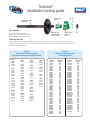
Scotseal
installation tooling guide
®
Standard plug
bushing
Standard tool handle
(#450237)
Washer
Tool selection
SKF Scotseal® Classic and Scotseal®
Longlife are to be installed using only SKF
Scotseal installation tools. (See Chart A)
Seal drive plate
(interchangeable see chart below)
Centering plug
(See chart
below)
Nut
Centering the seal
Precisely matched centering plugs are engineered to fit within the inside diameter of the inner bearing cone and allow accurate
centering of the Scotseal in the bore of the hub, as well as preventing cocking of the seal. Chart B below provides correct matchup
of bearing cone and centering plug.
Chart A
Drive plates & seal matchups
Chart B
Matchup of bearing cones
& centering plugs
(Drive plates in bold numbers with matching seal numbers)
427
34387
36285
36358
36365
428
31175
31244
31281
31323
32470
435
47690
47693
47696
47697
47698
48000
436
34975
35000
35060
35066
35072
35075
35103
441
40086
445
39380
39420
39425
42550
42672
42800
446
43860
43865
43875
46390
47483
48690
48794
48796
48884
50124
448
38709
39988
449
47699
451
46305
46308
452
42623
42624
42631
457
40040
40136
40139
461
45152
45160
45162
462
38747
38750
38780
463
27438
28758
28820
28832
465
43752
43764
43800
473
39380
(w/disc
brks.)
474
52658
484
44922
44964
45010
45099
45103
Bearing
cone no.
495-AX
BR497
BR539
555-S
557-A
BR559
BR560
BR567
BR568
BR575
BR580
BR582
BR593
BR594
594-A
BR595
BR596
BR598
598-A
BR639
BR641
BR659
BR663
663-A
BR664
BR665
665-A
681-A
BR683
BR687
BR749
749-A
756-A
BR758
BR759
BR760
BR776
BR780
BR3778
BR3982
BR3984
BR4595
BR5557
Centering
plug no.
Bearing
cone no.
Centering
plug no.
708
711
701
702
703
704
706
707
731
708
710
710
712
715
715
710
711
714
714
704
706
708
710
710
732
711
711
714
715
718
719
710
709
711
712
717
715
718
730
704
706
701
721
BR5760
BR6379
BR6386
6386-A
BR6389
BR6461
6461-A
BR6559
BR6580
BR28995
BR33281
BR33287
BR33895
BR39580
BR39581
BR39585
BR42688
BR45284
BR45285
BR47678
BR47686
BR47687
BR52400
BR52401
JH217249
JM205149-A
JM207049-A
JM511946
JM716649
JM718149
JM719149
HM212044
HM212046
HM212047
HM212049-X
HM212049
HM215249
HM218248
HM516449
HM518445
H715345
708
705
706
706
706
708
708
710
712
703
716
707
701
702
702
704
708
700
700
708
710
710
718
718
719
722
723
724
719
713
733
703
704
704
706
706
707
713
710
712
716
Wheel bearing
adjustment procedure
Manual adjustment
Step 1: L ubricate the wheel bearing with clean axle lubricant of the same type used in the axle sump or hub assembly.
Note: Never use an impact wrench when tightening or loosening lug nuts or bolts during the procedure.
Initial
adjusting
nut torque
Step 2
Initial
back off
Step 3
Back off
Final
adjusting
nut torque
Axle type
Threads
per inch
Step 4
Steer
(front)
non-drive
200 lb•ft
(271N•m)
While rotating
wheels
One full turn
50 lb•ft
(68N•m)
While rotating
wheels
Jam nut torque
Final
back off
Step 5
Step 6
12
1/6 Turn *
18
1/4 Turn *
14
Torque
Specifications
Dowel type
washer
300-400 lb•ft
(407-542N•m)
16
Tang type
washer**
200-275 lb•ft
(271-373N•m)
12
2 5/8”
(66.7mm)
and over
200-300 lb•ft
(271-407N•m)
Drive
1/4 Turn
1/4 Turn
16
Step 8
Install cotter pin to
lock axle nut in position
200-300 lb•ft
(271-407N•m)
12
Acceptable
end play
Step 7
Less than
2 5/8”
(66.7mm)
1/2 Turn
18
Trailer
Nut size
.001”-.005”
(.025mm- .127mm)
As measured
per procedure with
dial indicator
*If dowel pin and washer (or washer tang and nut flat) are not aligned, remove the washer, turn it over, and reinstall. If required, loosen the inner (adjusting) nut just enough for alignment.
**Bendable type washer lock only: Secure nuts by bending one wheel nut washer tang over the inner and outer nut. Bend the tangs over the closest flat perpendicular to the hang.
Printed with permission of the TMC, Reference RP618A.
PreSet wheel bearing adjustment procedure
ConMet PreSet hub assemblies are equipped with specially, half-toleranced bearings and a spacer, and require a specific bearing adjustment
procedure. Use the OEM seal, Scotseal PlusXL, when servicing a PreSet hub assembly.
1)Lubricate the wheel bearing with clean axle lubricant of the
same type used in the axle sump or hub assembly. Never use
an impact wrench when tightening or loosening lug nuts or
bolts during this procedure.
2a)For one-piece spindle nut systems, torque the nut to a
minimum of 300 ft. lbs. Do not back off the spindle nut.
Advance the nut until engagement takes place and the nut
is locked.
2b)For a double nut or jam nut system, torque the inner nut to
300 ft. lbs. Do not back off the spindle nut. Install the outer
nut with 200 ft. lbs. of torque.
Note: Be sure to engage any locking device.
2c)Per ConMet Service Manual, rev E, 12-2010, ConMet does not
recommend the use of a one-piece castellated type nut system
for use with PreSet hubs.
End play verification procedure
Wheel bearing end play is the free movement of the wheel assembly along the spindle axis. It is recommended, for verification
purposes, that wheel bearing end play be measured with a dial indicator.
Step 1 Make sure the brake drum to hub fasteners are tightened
to the manufacturers’ specifications.
Step 2 Attach a dial indicator with its magnetic base at the bottom
of the hub or brake drum.
Step 3 Adjust the dial indicator so that its plunger or pointer
is against the end of the spindle with its line of action
approximately parallel to the axis of the spindle.
Note: F
or aluminum hubs, attach the magnetic base of the
indicator to the end of the spindle with the plunger against
the hub or brake drum.
• SKF and Scotseal are registered trademarks of the SKF Group.
• PreSet and ConMet are registered trademarks of Consolidated Metco, Inc.
• TFO and Trouble-Free Operation are registered trademarks of SKF Group.
Step 4 Set the dial indicator to zero by rotating the gauge face
so the zero mark lines up with the gauge needle. For digital
indicators, push the zero-out button.
Step 5 Grasp the wheel assembly at the 3 o’clock and 9 o’clock
positions, while oscillating it to seat the bearings. Read
bearing end play as the total indicator movement.
Note: If end play is not within specifications, repeat wheel bearing
adjustment procedure until end play is within proper range.
View detailed technical and product
videos at www.skfpartsinfo.tv
Follow us on Twitter @skfpartsinfo to
stay on top of all the latest technical and
product information.
©SKF Group 2010
Printed in U.S.A.
457373
(Revised 11/14)
SKF VSM
890 N. State Street
Suite 200
Elgin, IL 60123
800-882-0008
www.vsm.skf.com