1
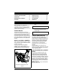
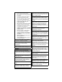
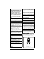
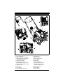
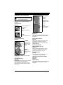
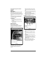
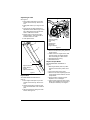
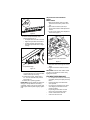
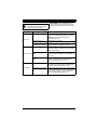
®
Path-Pro
Owner/Operator Manual
Manuel du Propriétaire/Utilisateur
Models
938030 – SS21
(SN 000101 +)
938031 – SS21
(SN 000101 +)
938032 – SS21E
(SN 000101 +)
938033 – SS21EC
(SN 000101 +)
938034 – SS21E
(SN 000101 +)
E10
The use of any gasoline exceeding 10% ethanol (E10) or
10% MTBE will void the product warranty.
L’utilisation d’une essence contenant plus de 10%
d’éthanol (E10) ou de 10% de MTBE annulent la garantie.
ENGLISH
FRANÇAIS
04535800B • 7/14
Printed in USA
TABLE OF CONTENTS
SAFETY. . . . . . . . . . . . . . . . . . . . . . . . . . 4
TROUBLESHOOTING . . . . . . . . . . . . . 19
CONTROLS AND FEATURES . . . . . . . 10
SERVICE PARTS . . . . . . . . . . . . . . . . . 20
OPERATION . . . . . . . . . . . . . . . . . . . . . 11
SPECIFICATIONS . . . . . . . . . . . . . . . . . 20
MAINTENANCE SCHEDULE . . . . . . . . 17
ACCESSORIES. . . . . . . . . . . . . . . . . . . 20
STORAGE . . . . . . . . . . . . . . . . . . . . . . . 18
WARRANTY . . . . . . . . . . . . . . . . . . . . . 21
INTRODUCTION
THE MANUAL
Before operating unit, carefully and
completely read your manual. The contents
will provide you with an understanding of
safety instructions and controls during normal
operation and maintenance.
ENGINE MANUAL
The engine on this unit is covered by a
separate manual specific to the engine. This
manual is included in the literature package
that shipped with the unit. Refer to this
manual for engine service recommendations.
If the engine manual is not available, contact
the engine manufacturer for a replacement
manual.
MODEL AND SERIAL NUMBERS
When ordering replacement parts or making
service inquiries, know the Model and Serial
numbers of your unit.
Numbers are located on the product
registration form in the unit literature
package. They are also printed on a serial
number label on your unit (see Figure 1).
•
Record unit model and serial numbers
here.
•
Record engine model and serial
numbers here.
PRODUCT REGISTRATION
The Ariens dealer should register the product
at the time of purchase. Registering the
product helps the company process warranty
claims or contact you with the latest service
information. Claims meeting requirements
during the limited warranty period will be
honored, whether or not the product
registration card is returned with proof of
purchase.
Customer Note: If the Dealer does not
register your product, please fill out, sign and
return the product registration card to Ariens
or go to www.ariens.com.
UNAUTHORIZED REPLACEMENT
PARTS
1
Use only Ariens replacement parts. The
replacement of any part on this unit with
anything other than an Ariens authorized
replacement part may adversely affect the
performance, durability and safety of this unit
and may void the warranty. Ariens disclaims
liability for any claims or damages, whether
warranty, property damage, personal injury or
death arising out of the use of unauthorized
replacement parts.
NOTE: A Parts Manual may be downloaded
from www.ariens.com.
1. Unit Model & Serial Number Label
Figure 1
EN - 2
DELIVERY
Customer Note: If this product was
purchased without complete assembly and
instruction by a retailer, it is your
responsibility to:
• Read and understand all instructions
in this manual. If you do not
understand or have difficulty following
the instructions, contact your nearest
Ariens Dealer for assistance.
NOTE: To locate your nearest Ariens Dealer,
go to www.ariens.com.
WARNING: Improper assembly or
adjustments can cause serious
injury.
Before Operating Unit
1. Make sure all assembly has been
properly completed.
2. Understand all Safety Precautions
provided in the manuals.
3. Review control functions and operation
of the unit. Do not operate the unit
unless all controls function as described
in this manual.
4. Review recommended maintenance and
adjustments.
5. Review Limited Warranty policy.
6. Fill out a product registration card and
return it to Ariens Company or register
the product at www.ariens.com.
DISCLAIMER
Ariens reserves the right to discontinue,
change and improve its products at any time
without notice or obligation to the purchaser.
The descriptions and specifications contained
in this manual were in effect at printing.
Equipment described within this manual may
be optional. Some illustrations may not be
applicable to your unit.
EN - 3
SAFETY
2. Warning
WARNING: This snow thrower is
capable of crushing or amputating
body parts. Failure to observe the
safety instructions in the manuals
and on decals could result in serious
injury or death.
Tragic accidents can occur if the
operator is not alert to the presence
of children. Never assume that
children will remain where you last
saw them.
Gasoline is extremely flammable
and the vapors are explosive;
handle with care.
Stop engine and allow moving parts
to stop before leaving operator’s
position.
Read these safety rules and follow them
closely. Failure to follow these rules could
lead to loss of control of unit, severe personal
injury or death to you or bystanders or result
in damage to property or the machine.
Safety Alert Symbols
The safety alert symbols above and signal
words below are used on decals and in this
manual.
Read and understand all safety messages.
3. Caution
CAUTION: Indicates a
POTENTIALLY HAZARDOUS
SITUATION! If not avoided, MAY
RESULT in minor or moderate injury.
It may also be used to alert against
unsafe practices.
4. Notice
NOTICE: Indicates information or procedures
that are considered important but not hazard
related. If not followed property damage
could result.
5. Important
IMPORTANT: Indicates general reference
information worthy of special attention.
SAFETY DECALS
These are safety alert
symbols. They mean:
• ATTENTION!
• YOUR SAFETY IS
INVOLVED!
When you see this symbol:
• BECOME ALERT!
• OBEY THE
MESSAGE!
SIGNAL WORDS
WARNING: Indicates a
POTENTIALLY HAZARDOUS
SITUATION! If not avoided, COULD
RESULT in death or serious injury.
This snow thrower is capable of crushing or
amputating body parts. Failure to observe the
following safety instructions could result in
serious injury or death.
The safety decals on your machine are visual
reminders of the important safety information
found in this manual. All messages found on
your unit must be fully understood and
carefully followed. Safety decals found on the
machine are explained below.
Always replace missing or damaged safety
decals. Replacement decal information is in
the Parts Manual for your machine. Decals
can be ordered from your dealer.
See Figure 2 for safety decal locations.
1. Danger
DANGER: Indicates an
IMMINENTLY HAZARDOUS
SITUATION! If not avoided, WILL
RESULT in death or serious injury.
EN - 4
1. Safety Decal Identification
2. DANGER!
4
08000917
Danger!
1
ROTATING PARTS! ONLY
use clean-out tool to clear
blockages. NEVER use
your hands. High speed
auger/impeller rotates
below discharge
opening. Wait for all
moving parts to stop
before removing clogs or
servicing.
3
2
Figure 2
2. Safety Decal Description
3. DANGER!
1. DANGER!
Danger!
Danger!
ROTATING PARTS.
Keep clear of auger while
engine is running.
• Read Operator’s
Manual.
• Allow operation only by
properly trained adult,
never children.
• Stop engine and
remove ignition key
prior to leaving the
operator’s position for
any reason.
• Keep all controls,
guards and safety
devices properly
serviced and functional.
• Never direct discharge
towards persons or
property that may be
injured or damaged by
thrown objects.
Read Owner/Operator
Manual.
Do not operate in rain.
EN - 5
Training
4. DANGER!
Read, understand and follow all instructions
on the machine and in the manual(s) before
operating this unit. Be thoroughly familiar
with the controls and the proper use of the
equipment. Know how to stop the unit and
disengage the controls quickly.
Danger!
Never allow children to operate the
equipment. Never allow adults to operate
the equipment without proper instruction,
including actual operation.
ONLY use clean-out tool to
clear blockages. NEVER
use your hands.
Keep the area of operation clear of all
persons, particularly small children. Keep
children under watchful care of a
responsible adult. Be alert and shut off unit if
children enter area.
Never direct discharge
towards persons or
property that may be
injured or damaged by
thrown objects.
Exercise caution to avoid slipping or falling,
especially when operating the snow thrower
in reverse.
Always remove key and/or wire from spark
plug before assembly, maintenance or
service. Unintentional engine start up can
cause death or serious injury.
Keep people away from
unit while operating. Keep
children out of work area
and under watchful care of
a responsible adult.
Complete a walk-around inspection of the
unit to understand the unit, your work area,
and all safety decals.
Stop engine, remove key,
read manual before
making any repairs or
adjustments.
Preparation
Always check overhead and side clearances
carefully before operation.
Always be aware of traffic when operating
along streets or curbs.
Read Owner/Operator
Manual.
Thoroughly inspect the area where the
equipment is to be used and remove all
pets, doormats, sleds, boards, toys, wires,
debris and other foreign objects.
Disengage all clutches and shift into neutral
before starting the engine (motor).
Wear appropriate hearing
protection.
Use only approved extension cords and
receptacles when starting units equipped
with electric starter. Do not connect electric
starter cord to any wiring system that is not a
three-wire grounded system.
RULES FOR SAFE OPERATION
This snow thrower is capable of amputating
hands and feet and throwing objects. Failure
to observe the following safety instructions
could result in serious injury.
The following safety instructions are based
on the B71.3 specifications of the American
National Standards Institute in effect at the
time of production.
EN - 6
Handle fuel with care; it is highly flammable.
• Use an approved fuel container.
• Never add fuel to a running engine or
hot engine.
• Fill fuel tank outdoors with extreme
care. Never fill fuel tank indoors.
• Never fill containers inside a vehicle
or on a truck or trailer bed with a
plastic liner. Always place containers
on the ground, away from your
vehicle, before filling.
• When practical, remove gas-powered
equipment from the truck or trailer
and refuel it on the ground. If this is
not possible, then refuel such
equipment on a trailer with a portable
container, rather than from a gasoline
dispenser nozzle.
• Keep the nozzle in contact with the
rim of the fuel tank or container
opening at all times, until refueling is
complete. Do not use a nozzle lockopen device.
• Replace gasoline cap securely and
wipe up spilled fuel.
• If fuel is spilled on clothing, change
clothing immediately.
Adjust the auger/impeller housing height to
clear gravel or crushed rock surface.
Always allow unit and engine to adjust to
outdoor temperature before clearing snow.
Operation
Never leave a running unit unattended.
Always shut off engine before leaving unit.
Always remove key to prevent unauthorized
use.
Do not put hands or feet near or under
rotating parts. Keep clear of the discharge
opening at all times.
Moving and/or rotating parts can cut off body
parts such as fingers or a hand. Always
keep hands, feet and clothing away from all
rotating parts during operation.
Do not touch unit parts which might be hot
from operation. Allow parts to cool before
attempting to maintain, adjust or service.
Exercise extreme caution when operating on
or crossing gravel drives, walks or roads.
Adjust skid shoes so scraper blade does not
contact gravel. Stay alert for hidden hazards
or traffic.
After striking a foreign object, stop the
engine (motor), remove the wire from the
spark plug, thoroughly inspect the snow
thrower for any damage, and repair the
damage before restarting and operating the
snow thrower.
If the unit should start to vibrate abnormally,
stop the engine (motor) and check
immediately for the cause.
Stop the engine (motor) whenever you leave
the operating position, before unclogging the
auger/impeller housing or discharge guide,
and when making any repairs, adjustments
or inspections.
When leaving the machine unattended,
disengage the power take-off, lower the
attachment, set the parking brake, stop the
engine and remove the key.
When cleaning, repairing or inspecting the
snow thrower, make certain the
auger/impeller and all moving parts have
stopped. Disconnect the spark plug wire and
keep the wire away from the plug to prevent
someone from accidentally starting the
machine.
Never attempt to make any adjustments
while the engine (motor) is running (except
when specifically recommended by
manufacturer).
Always keep hands away from all pinch
points.
Thrown objects can cause injury. Check for
weak spots on docks, ramps or floors. Avoid
uneven work areas and rough terrain. Stay
alert for hidden hazards.
Do not run the engine (motor) indoors,
except when starting the engine and for
transporting the snow thrower in or out of the
building. Open the outside doors; exhaust
fumes are dangerous.
Never operate the snow thrower without
proper guards and other safety protective
devices in place.
Never direct the discharge toward people or
areas where property damage can occur
from thrown objects. Keep children and
others away.
Do not overload the machine capacity by
attempting to clear snow at too fast a rate.
Slow down and turn corners slowly.
Never operate the machine at high transport
speeds on slippery surfaces. Look behind
and use care when backing.
EN - 7
Do not operate in reverse unless absolutely
necessary. Always back up slowly and look
down and behind before and while backing.
Maintenance and Storage
Secure unit so it will not tip over during
maintenance.
Do not carry passengers.
Before cleaning, removing clogs or making
any inspections, repairs, etc., disengage
clutch(es), stop unit and engine, remove
key, allow moving parts to stop. Allow hot
parts to cool.
Disengage attachment drive when traveling
from one work area to another.
Disengage power to the auger/impeller
when snow thrower is transported or not in
use.
Make sure the equipment is in safe working
condition. Check shear bolts and other bolts
and hardware at frequent intervals for proper
tightness. If components are worn or
damaged, replace with manufacturer’s
recommended parts.
Use only attachments and accessories
approved by the manufacturer of the snow
thrower (such as wheel weights,
counterweights or cabs).
This product is equipped with an internal
combustion type engine. Do not use unit on
or near any unimproved, forest-covered or
brush-covered land unless exhaust system
is equipped with a spark arrester meeting
applicable local, state or federal laws. A
spark arrester, if it is used, must be
maintained in effective working order by
operator.
Check clutch and brake operation
frequently.
Do not change engine governor settings or
over-speed engine.
Adjust and service as required. All motion of
drive wheels and auger/impeller must stop
quickly when control levers are released.
Never operate the snow thrower without
good visibility or light. Falling snow, fog, etc.
can reduce vision and cause an accident.
Always maintain unit in safe operating
condition. Damaged or worn out muffler can
cause fire or explosion.
Never operate unit after or during the use of
medication, drugs or alcohol. Safe operation
requires complete and unimpaired attention
at all times.
Keep unit free of ice or other debris. Clean
up oil or fuel spills.
Never allow anyone to operate this unit
when their alertness or coordination is
impaired.
Never store the machine with fuel in the fuel
tank inside a building where ignition sources
are present such as hot water heaters,
space heaters or clothes dryers. Allow the
engine to cool before storing in any
enclosure or covering the unit.
Avoid sharp edges. Sharp edges can cut.
Do not throw snow any higher than
necessary.
Clearing a Clogged Discharge Chute
Hand contact with the rotating
auger/impeller inside the discharge chute is
the most common cause of injury associated
with snow throwers. Never use your hand to
clean out the discharge chute.
To clear the chute:
1. SHUT THE ENGINE OFF!
2. Wait 10 seconds to be sure the
auger/impeller blades have stopped
rotating.
3. Always use a clean-out tool, not your
hands.
Always keep protective structures, guards,
and panels in good repair, in place and
securely fastened. Never modify or remove
safety devices.
Always refer to operator's manual for
important details if the snow thrower is to be
stored for an extended period.
Maintain or replace safety and instruction
labels as necessary.
Run the machine a few minutes after
throwing snow to prevent freeze-up of the
auger/impeller.
EN - 8
Never fill fuel containers inside a vehicle or
on a truck or trailer bed with a plastic liner.
Always place containers on the ground away
from your vehicle before filling.
Personal Protection
Do not operate the equipment without
wearing adequate winter garments. Avoid
loose fitting clothing that can get caught in
moving parts. Wear footwear that will
improve footing on slippery surfaces.
Wear adequate safety gear, including safety
glasses with side shields, and protective
gloves.
When practical, remove gas-powered
equipment from the truck or trailer and refuel it
on the ground. If this is not possible, then
refuel on a trailer with a portable container,
rather than from a gasoline dispenser nozzle.
Do not wear loose clothing or jewelry, and tie
back hair that may get caught in rotating
parts.
Keep the nozzle in contact with the rim of
the fuel tank or container opening at all
times until fueling is complete. Do not use a
nozzle lock-open device.
Protect eyes, face and head from objects
that may be thrown from unit. Wear
appropriate hearing protection.
If fuel is spilled on clothing, change clothing
immediately.
Properly remove fuel before tipping unit up
onto housing, so no spills will occur.
Slope Operation
Operate the snow thrower on level surfaces.
Stay off slopes and slippery surfaces.
Do not clear snow across the face of slopes;
go up and down. Exercise extreme caution
when operating on slopes. Do not attempt to
clear steep slopes.
Use a slow speed to avoid stops or shifts on
slopes. Avoid starting or stopping on a
slope.
Do not park unit on a slope unless
absolutely necessary. When parking on a
slope always block the wheels.
Do not operate near drop-offs, ditches, or
embankments. Unit can suddenly turn over if
a wheel is over the edge of a cliff or ditch, or
if an edge caves in.
Towing/Transporting
Always shut off engine, remove key and
close fuel shut-off valve or drain fuel when
transporting unit on a truck or trailer.
Use extra care when loading or unloading
unit onto trailer or truck. Secure unit chassis
to transport vehicle. Never secure from rods
or linkages that could be damaged. Do not
transport machine while engine is running.
Accessories
Use only Ariens Company-recommended
attachments that are appropriate to your use
and can be used safely in your application.
OPERATOR ZONE
This unit is designed to be operated by one
person located in the operator zone (see
Figure 3).
Fuel
Do not run engine in an enclosed area.
Always provide good ventilation. Fumes
from engine exhaust can cause injury or
death.
Fuel is highly flammable and its vapors are
explosive. Handle with care. Use only an
approved gasoline container with an
appropriately sized dispensing spout.
No smoking, No sparks, No flames. Always
allow engine to cool before servicing.
Never fill fuel tank when engine is running or
hot from operation.
Never fill or drain fuel tank indoors.
Operator Zone
Replace fuel cap securely and clean up
spilled fuel.
Figure 3
EN - 9
CONTROLS AND FEATURES
1
3
2
11
4
5
22
12
13
14
20
6
7
8
9
21
15
16
10
18
19
17
Figure 4
1. Handlebar
2. Auger Control Bar
3. Auger Control Cable Assembly
4. Remote Discharge Chute Handle
Assembly (Model 938033)
5. Recoil Starter Handle
6. Discharge Chute Handle
(Models 938030, 031, 032, 034)
7. Discharge Chute Deflector Handle
8. Discharge Chute
9. Wing Knob
10. Auger Paddle
11. Oil Fill (Models 938030, 034)
12. Oil Fill (Models 938031, 032, 033)
13. Oil Drain Plug
14. Fuel Cap & Tank
15. Choke Control Knob
16. Engine Switch
17. Primer Bulb
18. Electric Start Button
(Models 938032, 033, 034)
19. Power Cord Receptacle
(Models 938032, 033, 034)
20. Fuel Shut-off Valve
21. Engine Guard
22. Fuel & Oil Door
EN - 10
OPERATION
CONTROLS AND FEATURES
WARNING: AVOID INJURY. Read
and understand the entire Safety
section before proceeding.
1
1. OFF
Use this position
to service,
transport or store
the unit.
See Figure 4 for all controls and features
locations.
Engine Switch
(Item 16)
2. ON
The engine switch has
two positions:
1
The fuel shut-off
valve has two
positions:
2
Use this position
to run the unit.
1. OFF
Engine will not start or
run.
Primer Bulb
(Item 17)
2
2. ON
Engine will start and run.
Recoil Starter Handle
(Item 5)
Choke Control Knob
(Item 15)
When pulled, handle will start engine. See
Start Engine (Recoil Start) on page 13.
IMPORTANT: Do not let handle snap back
against handlebar.
1. START
1
(Choke Closed):
Chokes off air to
engine for easier
starting.
Electric Start Button
Models 938032, 033, 034
(Item 18)
When pushed, button will start a properly
choked and cranked engine. See Start
Engine (Electric Start) on page 13.
2. RUN
2
Pushing primer bulb adds fuel to engine for
easier start. See Start Engine (Recoil Start)
on page 13.
(Choke Open):
Allows for normal
operation.
Discharge Chute
(Item 8)
Turn discharge chute handle (Item 6) to
control direction of snow discharge.
IMPORTANT: Gradually open choke after
engine starts.
Fuel Shut-off Valve
(Item 20)
IMPORTANT: The fuel shut-off valve MUST
be in the closed (off) position before
transporting the unit. The valve is closed
when it is narrow and vertical when viewed
from above.
Remote Discharge Chute Handle
Assembly
(Item 4)
Model 938033
Move remote discharge chute handle forward
or backward to control direction of snow
discharge.
EN - 11
GASOLINE
IMPORTANT: Always use gasoline that
meets the following guidelines:
• Clean, fresh gasoline.
• A minimum of 87 octane/87 AKI (91
RON). High altitude use may require a
different octane. Consult your Engine
Manual.
• Gasoline with up to 10% ethanol
(gasohol) or up to 10% MTBE (methyl
tertiary butyl ether) is acceptable.
• Use of any gasoline other than those
approved above may void the engine
warranty. If gas pumps are not marked
for the content of alcohol or ethers,
check ethanol and MTBE levels with
the fuel supplier.
• Do not modify the fuel system to use
different fuels.
• Never mix oil and gasoline.
NOTICE: All gasoline is not the same. If the
engine experiences starting or performance
problems after using a new gasoline, switch
to a different fuel provider or fuel brand.
IMPORTANT: Excessively oxygenated or
reformulated fuels (fuels blended with
alcohols or ethers) can damage the fuel
system or cause performance problems. If
any undesirable operating problems occur,
use a gasoline with a lower percentage of
alcohol or ether.
Fuel Tank
To add fuel:
1. Turn engine off and let cool for at least
three minutes.
2. Open fuel and oil door (Item 22) and
clean fuel cap and surrounding area to
prevent moisture and debris from
entering fuel tank.
3. Remove fuel cap.
IMPORTANT: Refer to Engine Manual for
correct type and grade of fuel.
4. Fill fuel tank to bottom of filler neck. See
SPECIFICATIONS on page 20 for fuel
tank capacity.
IMPORTANT: Do not overfill! This equipment
and/or its engine may include evaporative
emissions control system components,
required to meet EPA and/or CARB
regulations, that will only function properly
when the fuel tank has been filled to the
recommended level. Overfilling may cause
permanent damage to evaporative emissions
control system components. Filling to the
recommended level ensures a vapor gap
required to allow for fuel expansion. Pay
close attention while filling the fuel tank to
ensure that the recommended fuel level
inside the tank is not exceeded. Use a
portable gasoline container with an
appropriately sized dispensing spout when
filling the tank. Do not use a funnel or other
device that obstructs the view of the tank
filling process.
5. Replace fuel cap and tighten.
6. Clean up any spilled fuel and close fuel
and oil door.
Fuel Stabilizer
Gasoline left in the fuel system for extended
periods without a stabilizer will deteriorate,
resulting in gum deposits in the system.
These deposits can damage the carburetor
and the fuel hoses, filter and tank. Prevent
deposits from forming in the fuel system
during storage by adding a quality fuel
stabilizer to the fuel. Follow the
recommended mix ratio found on the fuel
stabilizer container.
ENGINE OIL
Models 938031, 032, 033
To check oil level:
1. Turn engine off and let cool for at least
three minutes.
2. Open fuel and oil door (Item 22) and
remove cap from oil fill.
3. Check oil level on dipstick. Oil level must
be maintained at safe operating level.
See SPECIFICATIONS on page 20. See
Engine Manual for detailed information.
4. Replace cap and close door.
To add oil:
1. Turn engine off and let cool for at least
three minutes.
2. Open fuel and oil door (Item 22) and
remove cap from oil fill.
3. Add 5W-30 oil and replace cap. Do not
overfill.
4. Clean up any spilled oil and close door.
Models 938030, 034
To check oil level:
1. Turn engine off and let cool for at least
three minutes.
2. Remove cap from oil fill (Item 11).
3. Check oil level on dipstick. Oil level must
be maintained at safe operating level.
See SPECIFICATIONS on page 20. See
Engine Manual for detailed information.
4. Replace cap.
EN - 12
Start Engine (Electric Start)
Models 938032, 033, 034
To add oil:
1. Turn engine off and let cool for at least
three minutes.
2. Remove cap from oil fill (Item 11) and
add 5W-30 oil. Do not overfill.
3. Replace cap.
4. Clean up any spilled oil.
1. Check oil level. See Engine Oil on
page 12.
2. Position discharge chute (Item 8) in a
safe direction.
3. Connect a power cord to power cord
recepticle (Item 19) and then plug cord
into a wall outlet.
TRANSPORTING UNIT
1. Always shut off engine, remove key and
close fuel shut-off valve when
transporting on a truck or trailer.
2. Use extra care when loading or
unloading onto truck or trailer. Do not lift
using discharge chute handle (Item 6).
3. Secure unit chassis to transport vehicle.
Never secure from rods or linkages that
could be damaged.
4. Do not transport unit while engine is
running.
OPERATION
Start Engine (Recoil Start)
1. Check oil level. See Engine Oil on
page 12.
2. Position discharge chute (Item 8) in a
safe direction.
3. Move engine switch (Item 16) to ON
position.
4. Open fuel shut-off valve (Item 20).
5. If engine is cold, turn choke (Item 15) to
CLOSED position.
NOTICE: Do not apply choke to a warm
engine.
6. Push primer bulb (Item 17) twice.
NOTICE: Do not push primer bulb to start a
warm engine.
7. Slowly pull recoil starter handle (Item 5)
until engine compression makes pulling
difficult. Let starter rewind a little, and
then pull smoothly and quickly to start
engine.
8. Repeat step 7 as needed.
9. Gradually open choke after engine
starts.
IMPORTANT: If engine does not start after
three attempts, see TROUBLESHOOTING
on page 19.
10. Pull auger control bar (Item 2) back to
handlebar to start auger; release bar to
stop auger.
CAUTION: Use cord that is minimum of
13 amp, 16 Gauge, 3 wire grounded plug, UL
listed, CSA Certified. Cord must be labeled
suitable for outdoor use.
4. Move engine switch (Item 16) to ON
position.
5. Open fuel shut-off valve (Item 20).
6. If engine is cold, turn choke (Item 15) to
CLOSED position.
NOTICE: Do not apply choke to a warm
engine.
7. Push primer bulb (Item 17) twice and
then press electric start button (Item 18).
NOTICE: Do not push primer bulb to start a
warm engine.
8. When engine starts, disconnect power
cord from wall outlet, then disconnect
cord from power cord recepticle.
IMPORTANT: If engine does not start after
three attempts, see TROUBLESHOOTING
on page 19.
9. Pull auger control bar (Item 2) back to
handlebar to start auger; release bar to
stop auger.
Discharge Chute
(Item 8)
Models 938030, 031, 032, 034
IMPORTANT: Always throw snow in a safe
direction, away from people and windows.
To control the discharge of snow:
1. Turn discharge chute handle (Item 6) in
the direction you want to throw snow.
2. Loosen wing knob (Item 9) and move
discharge chute deflector handle
(Item 7) up or down to control snow
throw height.
3. Tighten wing knob in desired position.
If chute becomes frozen and does not turn
correctly, take unit into warm area until
controls are unfrozen.
CAUTION: Do not use chute handle to lift the
unit.
EN - 13
Remote Discharge Chute Handle
Assembly
(Item 4)
Model 938033
IMPORTANT: Always throw snow in a safe
direction, away from people and windows.
Move remote discharge chute handle forward
or backward to choose the direction to throw
snow.
If chute becomes frozen and does not turn
correctly, take unit into warm area until
controls are unfrozen.
1. Move engine switch (Item 16) to OFF
position and remove key. Allow unit to
cool.
2. Tip unit back onto engine guard. Do not
tip further than engine guard allows or oil
may leak out of engine.
3. Remove six hex bolts and nuts per
paddle. Discard hardware, spacers and
paddles. See Figure 6.
NOTICE: Do not remove center plate.
2
Stop Engine
1. Release auger control bar (Item 2).
2. Turn engine switch (Item 16) to OFF
position.
3. If finished with unit, close fuel shut-off
valve (Item 20).
MAINTENANCE
3
1
Replace Auger Paddles
Replace auger paddles when paddles are
worn down to wear indicator holes. See
Figure 5.
1
1. Bolt and Nut Locations
2. Paddle
3. Center Plate
Figure 6
1
4. Position new paddles with wear indicator
holes on the left side as you face the
unit.
5. Install spacers into paddle holes and
secure paddle with new hex bolts and
nuts.
6. Tighten nuts to 50 – 90 in-lbf. Do not
overtighten.
7. When both paddles are installed, rotate
auger paddles by hand. Ensure that
paddles do not rub on housing and are
tightly attached.
8. Return unit to operating position.
9. Remove slack from auger cable. See
Adjust Auger Cable on page 15.
1
1. Wear Indicator Hole
Figure 5
IMPORTANT: Always replace auger paddles
in pairs. Do not replace one paddle only.
See MAINTENANCE SCHEDULE on
page 17.
EN - 14
Adjust Auger Cable
See Figure 7.
1. Move engine switch (Item 16) to OFF
position and remove key. Allow unit to
cool.
2. Slide plastic sleeve up to auger control
bar.
3. Insert Z-hook into appropriate hole in
adjustment bracket. When auger control
bar is disengaged, there should minor
slack in cable and no tension.
4. Engage auger control bar to ensure
proper operation. There should be no
excessive tension on cable.
5. Lower plastic sleeve.
1
1
1.
2.
3.
4.
5.
6.
2
6
5
4. Remove belt from drive pulley, idler and
engine sheave.
5. Install new belt on engine sheave, idler
and drive pulley. Route belt between
idler and belt finger on idler bracket.
6. Reinstall extension spring.
7. Reinstall belt cover.
4
Replace Scraper Blade
3
1.
2.
3.
4.
4
2
Extension Spring
Drive Pulley
Idler
Idler Bracket
Belt Finger
Engine Sheave
Figure 8
3
Auger Control Bar
Plastic Sleeve
Z-hook
Adjustment Bracket
Figure 7
Replace Belt
See MAINTENANCE SCHEDULE on
page 17.
1. Move engine switch (Item 16) to OFF
position and remove key. Allow unit to
cool.
2. Remove five tapping screws from belt
cover and remove belt cover. Retain all
parts.
3. Disconnect extension spring from idler
bracket. See Figure 8.
See MAINTENANCE SCHEDULE on
page 17.
1. Move engine switch (Item 16) to OFF
position and remove key. Allow unit to
cool.
2. Tip unit back onto engine guard.
3. Remove nuts, bolts, scraper support and
scraper blade. Retain hardware. Discard
scraper blade.
4. Check condition of scraper support.
Replace if worn or damaged.
5. Insert scraper support into new scraper
blade. The D-shaped cutout must be on
the left (drive belt side). See Figure 9.
EN - 15
Adjust Remote Chute Rotation
Cables
Model 938033
1. Move engine switch (Item 16) to OFF
position and remove key. Allow unit to
cool.
2. Open fuel and oil door (Item 22) to
access chute rotation cable adjustment
screws.
3. Loosen chute rotation cable adjustment
screws. See Figure 11.
Figure 9
1
6. Position scraper assembly under
housing. See Figure 10.
• D-shaped cutout must be on the left.
• Edge must point down and forward.
• Scraper assembly bolt holes must
align with square bolt holes in auger
housing.
1. Chute Rotation Cable Adjustment
Screws
Figure 11
1
1. Scraper Blade Edge
Figure 10
7. Move scraper assembly backward and
up until small lip on top of scraper blade
contacts bottom lip of housing.
8. Install bolts and nuts. Tighten nuts to
40 – 50 in-lbf. Threads must protrude
beyond the nut.
9. Return unit to operating position.
IMPORTANT: If auger paddles are pulling too
strongly or scraper blade is not clearing
completely, loosen nuts (do not remove) and
slide scraper assembly down slightly. Tighten
nuts.
4. Pull cable covers to the right to remove
slack.
5. Tighten screws and close fuel and oil
door.
IMPORTANT: Remote chute rotation cables
may also be accessed from under unit by
tipping unit forward.
FOR BEST PERFORMANCE
•
•
•
•
•
•
EN - 16
For complete snow removal, walk slowly
and slightly overlap each path previously
taken.
Position discharge chute downwind
when possible.
Do not pick up gravel and rocks. Push
down slightly on handlebar to avoid
picking up debris.
Inspect auger before each use and
remove any accumulation / debris.
Check oil level before each use.
Clean unit after each use.
MAINTENANCE SCHEDULE
WARNING: AVOID INJURY. Read
and understand the entire Safety
section before proceeding.
Interval
Task
Action
Clean unit.
Remove snow and debris with a soft-bristled
brush. Do not use harsh abrasives or cleaners.
NOTICE: Protect painted surfaces with
automotive-type wax.
Check engine oil.
See Engine Oil on page 12.
Follow engine
maintenance schedule.
Perform scheduled engine maintenance. Refer
to Engine Manual for detailed instructions.
Check fasteners.
Check all fasteners. Replace missing or
damaged fasteners. Tighten all nuts and bolts to
correct torque values.
Check auger paddle
wear.
Replace when auger paddles are worn to wear
indicator holes. See Replace Auger Paddles on
page 14.
Check scraper blade
wear.
Do not allow scraper blade to wear down too far
or auger housing will become damaged. See
Replace Scraper Blade on page 15.
Check belt wear.
Adjust auger cable as needed. Replace when
damaged or when auger stops or stutters during
operation. See Replace Belt on page 15.
Replace scraper blade.
Replace when damaged or when scraper blade
has been adjusted down as far as possible and
does not touch surface or clear properly. See
Replace Scraper Blade on page 15.
Each Use
Every 10 Hours
As Needed
IMPORTANT: Proper maintenance can
prolong the life of unit. The following chart
shows the recommended service schedule.
EN - 17
STORAGE
SHORT TERM
Never spray unit with high pressure water or
store unit outdoors.
Inspect unit for visible signs of wear,
breakage or damage and repair as needed.
Keep all nuts, bolts and screws properly
tightened and know unit is in safe working
condition.
Store unit in a cool, dry, protected area.
Protect bare-metal areas with a light coat of
oil or anti-rust compound.
LONG TERM
Perform all short term storage items.
Touch up all scratched painted surfaces.
Fuel System
Gasoline left in the fuel system for extended
periods without a stabilizer will deteriorate,
resulting in gum deposits in the system.
These deposits can damage the carburetor
and the fuel hoses, filter and tank. Prevent
deposits from forming in the fuel system
during storage by adding a quality fuel
stabilizer to the fuel. Follow the
recommended mix ratio found on the fuel
stabilizer container.
To treat the fuel system for storage:
1. Add fuel stabilizer (Ariens part number
00592900) according to manufacturer’s
instructions.
2. Run engine for at least 10 minutes after
adding stabilizer to allow it to reach the
carburetor.
Never store the engine with fuel in the fuel
tank inside of a building with potential
sources of ignition.
TO TAKE THE UNIT OUT OF
STORAGE
1. See the Engine Service Manual to
prepare engine for service.
2. Put fresh, clean fuel in the fuel tank.
3. Begin the maintenance schedule.
EN - 18
TROUBLESHOOTING
Problem
Engine will not
start.
Engine starts
hard or runs
poorly.
Excessive
vibration.
Probable Cause
Correction
Engine switch in OFF
position.
Move switch to ON position (see Engine Switch
on page 11).
Fuel shut-off valve in
OFF position.
Move valve to ON position (see Fuel Shut-off
Valve on page 11).
Fuel tank empty.
Fill fuel tank with fuel (see Gasoline on page 12).
Cord not plugged in
(electric start models
only).
Plug power cord in or replace worn cord. Reset
circuit breaker.
Engine not primed.
Press the primer bulb twice and start engine.
Spark plug
disconnected.
Connect spark plug.
Choke open / cold
engine.
Turn choke (see Choke Control Knob on page 11)
to CLOSED position, then press primer button
and start engine.
Engine flooded.
Turn choke to ON position and crank the engine
repeatedly until it starts.
Faulty spark plug.
Replace spark plug.
Faulty engine.
See your Ariens Dealer.
Fuel mixture too rich.
Turn choke to OPEN position. See Choke Control
Knob on page 11.
Faulty, fouled or
incorrectly gapped
spark plug.
Clean and properly set spark plug gap or see your
Ariens Dealer.
Fuel cap vent is
blocked.
Clear vent.
Loose parts or damaged Stop engine immediately. Replace auger paddles.
auger paddles.
See Replace Auger Paddles on page 14 or see
your Ariens Dealer.
Excessive snow Scraper blade is worn.
left behind.
Replace when damaged or when scraper blade
has been adjusted down as far as possible and
does not touch ground or clear properly. See
Replace Scraper Blade on page 15 or see your
Ariens Dealer.
Auger drive belt is loose Replace belt or adjust auger control cable. See
or damaged.
Replace Belt on page 15. See Adjust Auger Cable
on page 15. See your Ariens Dealer.
Snow does not
discharge.
Discharge chute is
clogged with snow.
Stop engine immediately. Clean discharge chute
and auger housing. DO NOT use your hands.
Auger paddles are worn Replace auger paddles. See Replace Auger
or damaged.
Paddles on page 14 or see your Ariens Dealer.
Remote
discharge chute
handle has
excessive play.
Remote chute rotation
cables are loose.
Adjust remote chute rotation cables. See Adjust
Remote Chute Rotation Cables on page 16 or see
your Ariens Dealer.
EN - 19
SERVICE PARTS
ACCESSORIES
See your authorized Ariens dealer for
genuine OEM service parts.
See your authorized Ariens dealer to add
these optional accessories to your unit.
Part No.
Qty
Description
Part No.
00592900
AR
Fuel Stabilizer (4 oz)
73801100
Sno-Thro Cover Kit
06900533
1
Auger Cable
70707600
Protective Floor Mat
Description
07200627
1
Auger Belt
73800600
Snow Shield Kit
21547400
1
Spark Plug
73800800
53802900
1
Auger Paddle
Replacement Kit
Remote Chute Rotation Kit
(Models 938030, 031, 032,
034)
53803100
1
Scraper Blade
Replacement Kit
73801000
Maintenance Kit*
53803800
1
Pawl Arm
Replacement Kit
Model Number
938030
*Includes 16 oz. 5W-30 engine oil, spark
plug, fuel stabilizer and non-stick spray
(Snow-Jet).
SPECIFICATIONS
938031
938032
938033
938034
Model
SS21
SS21
SS21E
SS21EC
SS21E
Starter
Recoil
Recoil
Electric /
Recoil
Electric /
Recoil
Electric /
Recoil
Engine
Engine
Ariens
Engine Model
Number
AX136
AX208
AX136
Engine Size
136cc
208cc
136cc
Max RPM
3600 ± 100
Oil Capacity: Pt. (L)
1.0 (.473)
Fuel Tank Capacity:
Qt. (L)
2.9 (2.7)
Fuel Octane Rating
See Engine Manual
Size and Weight
Length: in. (cm)
54.3 (137.9)
Width: in. (cm)
21.6 (54.9)
Height: in. (cm)
40.9 (103.9)
Weight: lbs. (kg)
87
(39.46)
91
(41.28)
EN - 20
95
(43.10)
97
(44.00)
91
(41.28)
Sno-Thro®, Sno-Tek® and
Chore Performing Equipment
Limited Warranty
Ariens Company (Ariens) warrants to the original purchaser that Ariens, Gravely, Parker, and Countax
®
®
brand chore performing equipment (including Sno-Thro and Sno-Tek equipment) purchased on or after
1/1/2013 will be free from defects in material and workmanship for the time period noted in the chart below.
Equipment put to personal use around a single household or residence is considered “Consumer Use”;
equipment put to any business use (agricultural, commercial, or industrial) or used at multiple locations is
considered “Commercial Use.” If any product is rented or leased, then the duration of these warranties shall
be 90 days after the date of purchase.
An authorized Ariens dealer (Ariens brand products), Gravely dealer (Gravely brand products), Parker dealer
(Parker brand products), or Countax dealer (Countax brand products) will repair any defect in material or
workmanship, and repair or replace any defective part, subject to the conditions, limitations and exclusions
set forth herein. Such repair or replacement will be free of charge (labor and parts) to the original purchaser
except as noted below.
Warranty
Code
Product Group
Warranty Period
Consumer Use
Warranty Period
Commercial Use
90 Days
PA
Log Splitters, Brushes, String Trimmers, Edgers
3 Years
PB
Professional Powered Brushes
3 Years
1 Year
PC
Tillers
2 Years
90 Days
PD
Vacuums, Blowers, Sweepers, Truck Loaders,
Lawn Rakes, Sprayers, Aerators, etc.
1 Year
1 Year
PE
Pressure Washer, Generators
3 Years
1 Year
SA
Professional Sno-Thro®
3 Years
1 Year
Compact, Deluxe, Platinum, AMP™ Sno-Thro ,
Path-Pro®
3 Years
90 Days
SC
Sno-Tek®
2 Years
90 Days
UA
Utility Vehicles
1 Year
1 Year
N/A
Service (Replacement) Parts
90 Days (no labor)
90 Days (no labor)
®
SB
Special Extensions
The chart below details special extensions to this warranty:
Warranty
Code
Warranty Exception
Warranty
Period
Use
Detail
SA
Cast Iron Auger
Gear Case
5 Years
All
SB
Cast Iron Auger
Gear Case
5 Years
Consumer
5 Years for Consumer use;
1 Year for Commercial Use
SB
Batteries for AMP™
®
Sno-Thro
2 Years
Consumer
100% first year; prorated second year.
EN - 21
5 Years for all users including
Commercial
Sno-Chore 2013
Exceptions and Limitations
The chart below details special exceptions to this warranty:
Warranty
Code
Warranty Exception
Warranty
Period
Use
Detail
All
Batteries
1 Year
All
All
Belts, Muffler, Tires
None
Commercial
These components are not covered
when used commercially.
All
Cloth, Plastic, and
Rubber Components
(Including Belts and
Cables)
Maximum
2 Years
All
Warranty is limited to 2 years for
consumer use. (1 year for warranty
code "PD".) Except as noted above,
these components are covered for
defect, not for wear.
Maximum
2 Years
All
Warranty is limited on idlers to
2 years for consumer use.
See Engine
Manufacturer’s
Warranty
All
Engines are covered by engine
manufacturer’s warranty. Refer to
engine manufacturer’s warranty
statement.
SA, SB,
Idlers
SC
All
Engines
Prorated
Customer Responsibilities
Register the product immediately at the time of sale. If the dealer does not register the product, the
customer must complete the product registration card in the literature package and return it to Ariens
Company, or register the unit online at www.ariens.com, www.gravely.com, www.countax.com or
www.parkersweeper.com.
To obtain warranty service, the original purchaser must:
• Perform the maintenance and adjustments explained in the Owner's Manual.
• Promptly notify Ariens or an authorized Ariens, Gravely, Parker or Countax service representative of
the need for warranty service.
• Transport the product to and from the place of warranty service at owner's expense.
• Have the warranty service performed by an authorized Ariens, Gravely, Parker or Countax service
representative.
To Find an Authorized Service Representative:
In the U.S. and Canada:
Use the dealer locator on our websites:
www.ariens.com
•
www.gravely.com
Or contact us by mail or by phone:
In the U.S., Canada, Mexico, Caribbean, In Europe, Asia, Africa or
Central and South America:
the Middle East:
Ariens Company
655 W. Ryan Street
Brillion, WI 54110
Phone: (920) 756 - 4688
www.ariens.com
Countax Ltd, Countax House
Great Haseley, Oxfordshire,
OX44 7PF
Phone: 0800 597 7777
www.countax.com
EN - 22
In Australia or New Zealand:
Ariens Company
Building 2
6 Wedgewood Rd.
Hallam, Victoria 3803 Australia
Phone: (03) 9796 4244
1800 335 489
www.ariens.com.au
Sno-Chore 2013
Exclusions – Items Not Covered by This Warranty
• Parts that are not genuine Ariens, Gravely, Parker or Countax service parts are not covered by this
warranty and may void the warranty.
• Damages resulting from the installation or use of any part, accessory, or attachment which is not
approved by the Ariens Company for use with product(s) identified herein are not covered by this
warranty.
• The following maintenance, service and replacement items are not covered by this warranty unless
they are noted in the Limitations section above: lubricants, spark plugs, oil, oil filters, air filters, fuel
filters, brake linings, brake arms, brake shoes, skid shoes, scraper blades, shear bolts, mower
blades, mower vanes, brushes, headlights, light bulbs, knives, cutters, and single-stage impellers.
• Any misuse, alteration, improper assembly, improper adjustment, neglect, or accident which
requires repair is not covered by this warranty.
• Use of gasoline blends exceeding 10% ethanol voids any and all warranties.
• Products are designed to the specifications in the area that the product was originally distributed.
Different areas may have significantly different legal and design requirements. This warranty is limited to the requirements in the area in which the unit was originally distributed. Ariens Company
does not warrant this product to the requirements of any other area. Warranty service is limited to
service within the area originally distributed.
• In countries other than the United States and Canada, contact the Ariens Company dealer for warranty policies that govern within your country. Rights may vary from country to country and within
any one country.
• Normal Wear: This warranty does not cover repair when normal use has exhausted the useful life of
a part such as a high pressure hose, spray wand, nozzles, trigger handle, supply hoses, quick couplers, gaskets, valves, pistons, pump valve assemblies, o-rings, water and oil seals.
Special Exclusions on Utility Vehicles
The following uses void the warranty terms on Utility Vehicles (Warranty Code UA):
• Renting or leasing the utility vehicle.
• Using the utility vehicle to tow or carry loads in excess of the limits specified in the Owner/Operator
Manual.
• Modifying the utility vehicle with parts and accessories that are not genuine or authorized Ariens or
Gravely parts or accessories.
• Modifying the utility vehicle without express written authorization from Ariens Company.
• Operating the utility vehicle when it has not been completely and properly assembled and
pre-delivered by an authorized Gravely dealer.
Disclaimer
Ariens Company may from time to time change the design of its products. Nothing contained in this warranty
shall be construed as obligating Ariens Company to incorporate such design changes into previously
manufactured products, nor shall such changes be construed as an admission that previous designs were
defective.
LIMITATION OF REMEDY AND DAMAGES
Ariens Company's liability under this warranty, and under any implied warranty that may exist, is limited to
repair of any defect in workmanship, and repair or replacement of any defective part. Ariens Company shall
not be liable for incidental, special, or consequential damages (including lost profits). Some states do not
allow the exclusion of incidental or consequential damages, so the above limitation or exclusion may not
apply to you.
AUSTRALIAN CONSUMER LAW
The following applies solely to warranties subject to Subsection 102(1) of the Australian Consumer Law: Our
goods come with guarantees that cannot be excluded by the Australian Consumer Law. You are entitled to a
replacement or refund for a major failure and for compensation for any other reasonably foreseeable loss or
damage. You are also entitled to have the goods repaired or replaced if the goods fail to be of acceptable
quality and failure does not amount to a major failure.
DISCLAIMER OF FURTHER WARRANTY
Ariens Company makes no warranty, express or implied, other than what is expressly made in this
warranty. If the law of your state provides that an implied warranty of merchantability, or an implied
warranty of fitness for particular purpose, or any other implied warranty, applies to Ariens Company,
then any such implied warranty is limited to the duration of this warranty. Some states do not allow
limitations on how long an implied warranty lasts, so the above limitation may not apply to you.
This warranty gives you specific legal rights, and you may also have other rights which vary from region to region.
EN - 23
Sno-Chore 2013
Ariens
655 West Ryan Street
Brillion, WI 54110
920-756-4688
Fax 920-756-2407
www.ariens.com
www.ariens.com.au