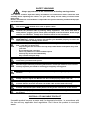
1
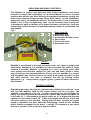
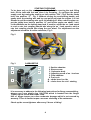
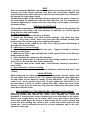
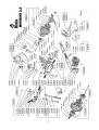
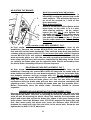
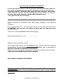
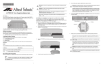
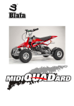
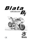
MINIBIKE
2,5
SAFETY WARNING
Always pay attention to the instructions and safety warnings below
This manual contains important safety information and instructions which should be read
carefully before operating the vehicle. For your own safety and the safety of others follow
these rules.
Neither manufacturer nor distributor is responsible for injuries caused by unsafe and improper
use of the vehicle.
This vehicle is not allowed to be used on public roads!
Unsafe and careless use of the vehicle can result in serious injuries. The driver can
minimize the potential risks by wearing safety equipment. The driver must wear a
safety helmet, goggles, gloves, elbow pads, kneepads, and firm footwear. Avoid rough
surfaces and obstacles. Always drive with both hands on the handlebars.
Always inspect the bike before each ride (refer to the article ‘INSPECTION AND
MAINTENANCE’). Failure to inspect and maintain your Quadard properly increases the
risk of an accident or damage to the vehicle.
Fuel and fuel vapour are highly toxic and flamable. Always be careful when handling
fuel – it can burn or poison you.
- stop the engine and turn off the fuel tap, keep naked flames and sparks away from
your bike.
- do not smoke near your bike.
- refuel only outdoors in a well ventilated space
- clean up any excess fuel immediately
- keep children and pets away
Always ride within the limits of vehicle/ rider and weather conditions to
unnecessary accidents and injuries.
avoid
Check-ups
Shut the engine off when performing maintenance check-ups otherwise You could be
severely injured if your hands or clothing get caught by moving parts.
Make sure the engine and exhaust are cold before performing any inspection of this
machine
Riding with a chain in poor condition or improperly adjusted can lead to serious injury.
Always, Inspect, Adjust and Maintain the drive chain properly before each ride.
Failure to inspect and properly maintain the brake increases the risk of having an
accident. Before each ride check the rear brake cable and the brake efficiency.
Riding with worn brake pads can reduce the braking performance and cause an
accident. Check and replace brake pads according to the instructions in this manual.
Using worn, improperly inflated, or incorrect tyres will reduce stability and can cause
an accident.
DISPOSAL OF UNUSABLE PRODUCT
Unusable product become a waste and it’s desposal should be in accordance with
the law and any applicable local regulations. Don’t throw this product to municipal
waste.
M I N I B I K E 2,5
SERVICE MANUAL FOR USE AND MAINTENANCE OF MINIBIKE
Before starting the operation of your Minibike, read thoroughly these
directions.
CONTENTS
PAGE
INTRODUCTION .............................................................................................................. 2
BASIC TECHNICAL DATA ...............................................................................................2
UNPACKING AND BASIC CONTROLS - FIG. 1 ............................................................3
SAFETY.............................................................................................................................3
BEFORE STARTING ....................................................................................................... 3
STARTING THE ENGINE - FIG. 2 ...................................................................................4
CARBURETOR - FIG. 3 ...................................................................................................4
RIDE ................................................................................................................................. 5
PERIODIC MAINTENANCE ..............................................................................................5
CHAIN SETTING ...............................................................................................................5
CLUTCH PADS REPLACEMENT .................................................................................... 5
ENGINE - EXPOSIVE VIEW..............................................................................................6
MINIBIKE - EXPLOSIVE VIEW - FIG. 5........................................................................... 7
PARTS LIST .................................................................................................................. 8,9
FRONT AND REAR BRAKES - FIG. 7 ...........................................................................10
ADJUSTING THE BRAKES - FIG. 4 ............................................................................. 11
FRONT BRAKES PADS REPLACEMENT - FIG. 7 ....................................................... 11
REAR BRAKES PADS REPLACEMENT - FIG. 7 ......................................................... 11
DISMANTELING AND MOUNTING THE FRONT WHEEL - FIG. 5................................11
DISMANTELING AND MOUNTING THE REAR WHEEL - FIG. 5..................................12
PINION EXCHANGE - FIG. 6 ..........................................................................................12
DISMANTELING AND ASSEMBLY OF AIR FILTER - FIG. 3 ........................................12
NON USE AND STORAGE PROCEDURE .....................................................................13
INTRODUCTION
Minibike 2,5 is intended for a drive on closed tracks with even, smooth, and
dust-free surface. Both growns - up and children can ride on the Minibike.
Children only under the supervision of a grown - up and responsible person. If
the terms of a track are fulfilled, the Minibikes can be used for races. Minibike
Blata should not be used during winter season and under bad weather
conditions. Usage under these conditions leads to abnormal mechanical wear
and corrosion of most minibike parts - especially those directly exposed to
climatic influences. Beside that, riding under these conditions increase the
risk of injury or health damage.
Minibike is equipped with a single - cylinder, two - stroke, petrol combustion
engine, with a front and rear disc brake, the rear one being controlled by a
lever on the left side of handlebars and the front one by a lever on the right
side of handlebars, when seeing in the ride direction. The fuel quantity
controlled by a handle on the right side of handlebars. The engine is fitted with
an air filter and a exhaust silencer. The driving moment transmission from
engine to the driven rear wheel is carried out by a chain drive the ratio of
which can by changed to a small extend by a sprocket wheel exchange on the
rear wheel.
BASIC TECHNICAL DATA
ENGINE:
TWO - STROKE ...............................................................AIR COOLED
CILINDER CAPACITY............................................................. 39,9 ccm
POWER OUTPUT.................................................. 2,5 kW at 8 700 rpm
TORGUE ..............................................................3,5 Nm at 6 000 rpm
CARBURETOR .................................................................DELL’ORTO
IGNITION......................................................................... ELECTRONIC
STARTING ..............................................................................MANUAL
CLUTCH .....................................................CENTRIFUGAL, FRICTION
FRAME:
WELDED ................................. OF HIGH - STRENGTH STEEL TUBES
LINING:
.................................................................................... THREE PARTED
BRAKES: FRONT WHEEL.....................................MECHANICAL DISC BRAKES
REAR WHEEL.......................................MECHANICAL DISC BRAKES
WHEELS: FRONT WHEEL............................................ OF LIGHT ALLOY 4” - 51
REAR WHEEL.............................................. OF LIGHT ALLOY 4” - 95
TIRES:
FRONT ......................................................... 3,00 - 4” WITH PATTERN
REAR............................................................ 3,00 - 4” WITH PATTERN
TUBES:
FRONT + REAR ....................................................................... 3,00 - 4”
FUEL:
......... MIXTURE OF PETROL 91 OR HIGHER OCTANE + 2-STROKE
SYNTHETIC OIL
MIXING RATIO .............................................................................. 50 : 1
TANK CAPACITY...................................................................... 1 LITRE
HIGHEST VELOCITY IN ACCORDANCE
WITH THE INSTALED RATIO:........................................... up to 28 mph ( 45 km/ h)
UNLOADED WEIGHT..........................................................................37,5 lb ( 17 kg)
CARRYING CAPACITY.....................................................................242 lb ( 110 kg )
BASIC DIMENSIONS:
LENGHT ........................................................................36,2” (920 mm)
WIDTH ..............................................................................20” (500 mm)
HEIGHT ...........................................................................20 ” (500 mm)
2
UNPACKING AND BASIC CONTROLS:
The Minibike is packed and delivered with folded handlebars and levers
mounted on them. After unpacking, set up the handlebars in such a function
position that will suit you best. However at maximum handlebars turning, the
brake levers must not bump into the lining. After setting - up the handlebars,
tighten the nuts 1 on handlebars sleeves, the brake levers 2, and acceleration
handle 3 acc. to Fig. 1.At tightening, don´t use an excessive force in order not
to damage the parts or threads, or to distort the tubes, and the like. Verify the
smooth and perfect movement of operating bowden cables of acceleration and
both brakes.
Fig. 1
Basic controls:
1. Handlebars nut
2
3
6
2
4
2. Brake lever bolts
3. Acceleration handle screws
5
4. Stop switch
5. Front brake lever
6. Rear brake lever
1
1
SAFETY
Minibike is not allowed to be used on public roads, as it doesn´t comply with
valid Safety Standards. It is forbidden to ride even where the traffic of larger
vehicles is possible. Minibike is intended for a drive on closed tracks with
even smooth and dust-free surface.For your own and other people´s safety
keep all advices and recommandations, how to use your minibike in a correct
and thoughtful way. serious injuries can result from unsafe operation of this
and other vehicles. You have to minimize the risk by wearing Safety
Equipment e. g. : safety helmet, goggles, gloves, guards of elbow and knees,
firm footwear.
BEFORE STARTING
Regarding the engine life time it is important the minibike to be well run - in as
this fact will manifest itself by the power output and life of engine. The
minibike is considered to be run - in after consuming five full fuel tanks by
riding. For brake-in period we use mixture of petrol and 2-stroke synthetic oil
in the ratio 30 : 1. After brake-in the petrol octane no. 91 or higher and 2-stroke
synthetic oil are mixed in ratio 50 : 1. Mix up throughly the mixture of fuel and
oil before pouring it into the tank. During brake-in don´t increase the engine
speed to maximum and don´t allow the overheating. Check the tire inflation
which should correspond to the driver ´s weight. The pressure in one wheel
has not to exceed 2,5 bar in the front and rear wheel.
3
STARTING THE ENGINE
To be done only on the starting stand - Fig. 2. After opening the tank filling
hole, fill the tank with fuel and close it by screwing - in cap.Open the petrol
supply cock by turning the small lever into position “ON”, Fig.3. Set the choke
lever into position “C” , Fig. 3. Without turning the accelerating handle, pull
gently twice the starting wire and by next quick pull start the engine. It is not
allowed to pull the starting wire up to full winding off. After a short engine run,
put the choke lever back to position “A” and let the engine run about 1 min.
Let the Minibike on the larking stand and, if need be, adjust the no - load speed
to such a rate lest coupling should take along the no - load speed to such a
rate lest coupling should take along the rear wheel. For adjustment use the
adjustment screw No. 4 on the carburetor, Fig. 3.
Fig. 2
Fig. 3
CARBURETOR
1
3
A
4
2
5
1. Suction chamber
2. Sleeve screw
3. Carburetor body
4. Adjusting screw of no - load run
5. Float chamber
6. Fuel cock
A – choke lever for ride
B – choke lever for cold - starting
It is necessary to adhere to the following instructions for flange reassembling:
always use a new plastic ring 110.078.00 which is inserted into the flange!
Tighten up the screw with torque 5 Nm.
Use of bigger torque can cause carburetor damage which is not covered by
warranty !! Use of smaller torque can cause slackeing of the carburetor.
Check up the screw tightness after every 5 hours of riding!
4
RIDE
After mounting the Minibike and slow turning the acceleration handle, you are
starting your ride. Before braking, turn back the acceleration handle and
depress slightly the front brake lever and then the rear brake lever. Beware of
the wheels not to get them in skid.
The Minibike engine will be switched off by pusching the red pusch - buttom of
the stop switch on handlerods. After the first half- hour ride it is necessary to
check the tightening of screws and nuts, especially of the engine. Check also
the brake setting.
PERIODIC MAINTENANCE
The periodic maintenance is the best way how to contribute to the machine life
prolongation, ride safety, and cost decrease. In addition, you will be spared
many worries, time and troubles.
A - Before every ride:
1. Check the Cables and efficiency of brakes.
2. Check the lubrication and chain tension settings. The chain free play
should
be (5 mm) (.200in) After every ride clean the minibike carefully and
keep it clean. Do not use aggressive cleaning detergents.
3. After 1-hour of use, wash the air filter in air drying spirits and lubricate it
with special oil for air filters.
B. After every 5 hours of riding:
4. Check the tightness of all bolts and nuts. Tighten carefully to prevent
damage to other parts.
5. Wash the air filter in gas and lubricate it with special oil for an air filters to
better catch the dust.
6. Clean carefully the carburetor float chamber.
7. Check the brake pads, the thickness of brake lining cannot be less than 1
mm (.039 in). Review the basic brake adjustment.
8. Check the state of the clutch pads - the thickness cannot be less than 1
mm (.039in).
C - Every time after 10 hours of riding:
9. Check the state of the clutch pads - the thickness cannot be less than 1 mm
(.039in).
CHAIN SETTING:
When setting up the chain attachment of the rear brake reaction catcher and
the rear wheel axle nut 920.011.01. Then tighten uniformly the chain tighteners
on both sides of rear wheel by means of nuts 920.009.01 , Fig. 5. When the
chain is set - up to reguired sag 0,196” (5 mm), tighten the nut 920.011.01 of
the rear wheel. If there is need to replace the chain, check also both chain
wheels. In case they are worn-out, they must be replaced by new ones at the
same time with the chain.
REPLACEMENT OF THE CENTRIFUGAL FRICTION CLUTCH PADS:
After unscrewing two side screws remove the front lining. Unscrew the
fastening screws and remove the chain cover. Release the chain and
dismantle it. Unscrew four screws keeping the cover with drum of the clutch.
Release the engine brace on the frame, shift it out, and remove the whole
cover with clutch drum. By means of pliers draw off the clutch springs and
loosen the pins holding the clutch levers. At the new clutch levers put the
clutch pins and at assembly proceed in a revers sequence and, in the end,
adjust the chain sag.
5
6
7
345.100.00
345.100.00
MINIBIKE - 2,5
110.000.00
110.001.00
110.001.01
110.002.00
110.004.00
110.004.01
110.004.02
110.004.03
110.005.00
110.006.00
110.006.01
110.006.02
110.006.03
110.008.00
110.011.00
110.015.00
110.017.00
110.019.00
110.020.00
110.021.00
110.022.00
110.023.00
110.024.00
110.028.00
110.031.00
110.032.00
110.053.00
110.055.00
110.056.00
110.057.00
110.059.00
110.060.00
110.063.00
110.065.00
110.067.00
110.068.00
110.069.00
110.069.01
110.069.02
110.069.03
110.070.00
110.072.00
110.073.00
110.074.00
110.075.00
110.076.00
110.077.00
110.078.00
110.080.52
110.097.00
110.098.00
110.099.00
110.100.00
110.101.00
110.102.00
110.103.00
110.104.00
110.105.00
110.185.00
MINIBIKE 2,5
ENGINE
ENGINE COMPLETE
ENGINE PROPER
CARBURETTER SHA 1412L
PISTON COMPLETE - A
PISTON COMPLETE - B
PISTON COMPLETE - C
PISTON COMPLETE - D
PISTON RING
PISTON - A
PISTON - B
PISTON - C
PISTON - D
WRIST - PIN
CRANK BALANCED
CLUTCH DISC
CLUTCH LEVER - 2 PCS
CLUTCH SCREW COMPLETE
CLUTCH SCREW SCREW
CLUTCH SPRING - SERIE 1,25 - 2PCS
CLUTCH SPRING - RACING 1,4 - 2PCS
CLUTCH SPRING - RACING 1,6 - 2PCS
CLUTCH DRUM
CLUTCH CASE
CLUTCH CASE COMPLETE
CLUTCH COMPLETE
ENGINE COVERING
ENGINE SEALING SET
FLANGE
DIAPHRAGM SEALING - 2PCS
DIAPHRAGM
DIAPHRAGM WASHER
SEALING ENGINE BLOCK
ENGINE BLOCK
DIAPHRAGM COMPLETE
SEALING
CYLINDER - A
CYLINDER - B
CYLINDER - C
CYLINDER - D
CYLINDER + PISTON COMPLETE
EXHAUST SEALING
PLASTIC CONECT, FUEL COCK
FUEL COCK
EXHAUST COMPLETE
EXHAUST SILENCER COMPLETE
SILENCER MASS
RING
JET 52
FLOAT CHAMBER SEALING
CARBURETOR SEALING 1
ADJUSTING SCREW
THROTTLE VALVE
CARBURETOR FILTER
NEEDLE VALVE
FLOAT
CARBURETOR SEALING 2
THROTTLE VALVE SEALING
JET SET
8
510.002.00
510.003.00
510.004.00
510.005.00
510.006.00
510.007.00
510.008.00
510.009.00
510.011.00
510.015.00
510.017.00
510.020.00
STARTER COMPLETE
STARTER ROPE
HOLDER
HOLDER
GUIDE BUSH
STARTER CASE
STARTER SPRING
RATCHET WHEEL
WASHER 4,5 x 16 x 1,5
WASHER 8,1 x 16 x 1
WASHER 6,1 x 16 x 1,5
PINION
111.001.01
FRAME
FRAME, VARNISHED
112.004.00
112.050.02
112.060.00
132.001.01
202.006.00
202.007.00
312.017.00
312.029.00
312.035.00
312.040.02
312.041.00
332.020.00
512.004.00
512.005.00
512.008.10
512.016.50
512.019.01
512.042.00
512.043.00
512.044.00
512.045.00
512.053.00
512.054.00
512.055.00
512.058.00
512.060.00
BRAKES
LIFTER, RIGHT
BRAKE HOLDER
BRAKE COMPLETE
FRONT BRAKE DISC 2,5 x 119
BOWDEN CABLE - FRONT BRAKE
BOWDEN CABLE - REAR BRAKE
LIFTER LEVER
SPRING, LEFT
WASHER 6,1 x 14 x 3
REAR BRAKE DISC 3,0 x 119
WASHER 10,5 x 18 x 3
NUT
HANDLE BAR LEVER, RIGHT
HANDLE BAR LEVER, LEFT
LIFTER, LEFT
TERM. CLAMP BOWDEN
WASHER
DISTANCE SLEEVE
BRAKE PIN
LIFTER PIN
BOWDEN HOLDER
FRONT BRAKE CASE - 1 PAIR
DISC BRAKE PADS - 1 PAIR
BRAKE COMPLETE
REAR BRAKE CASE - 1 PAIR
SPRING RIGHT
113.001.00
113.002.01
113.005.00
113.007.00
113.008.00
113.009.00
WHEELS
DISC 4" - 51
WHEEL COMP. 4" - 95 WITHOUT TIRE
TIRE WITH PATTERN 3,00 - 4"
TUBE 3,00 - 4"
AXLE OF WHEEL
AXLE OF WHEEL
113.015.00
113.016.00
113.019.00
113.020.00
513.011.03
513.011.04
513.011.07
DISTANCE SLEEVE, 14,5 mm
CHAIN ADJUSTER, COMPLETE
WHEEL COMP. 4" - 51 WITHOUT TIRE
DISC 4" - 95
DISTANCE SLEEVE 139,3mm
DISTANCE SLEEVE 84,5 mm
DISTANCE SLEEVE 85,3mm
114.001.01
114.002.30
114.003.01
114.004.00
114.005.00
114.006.30
114.007.00
114.008.00
114.015.00
114.016.00
334.009.00
514.008.00
LINING
LINING COMPLETE, NON VARNISHED
LINING COMPLETE, VARNISHED
FRONT LINING, NON VARNISHED
SADDLE, NON VARNISHED
FRONT FENDER, NON VARNISHED
FRONT LINING, VARNISHED
SADDLE VARNISHED
FRONT FENDER, VARNISHED
CHAIN COVER
CHAIN COVER, POLISHED
WINDSHIELD + RIVET
RUBBER WASHER 5 x 5,5 x 23,5
115.001.05
115.002.00
115.005.00
115.011.00
115.014.00
115.015.00
115.016.00
345.100.00
115.021.01
115.022.01
CONTROL
FORK LEFT WITH BRAKE HOLDER
FORK RIGHT
HANDLE BAR TUBE
THROTTLE GAS
BOWDEN DUST GUARD
HAND GRIPS - 2 PCS
GAS BOWDEN CABLE
CAP
HOLDER ABOVE - COMPLETE
HOLDER BELOW - COMPLETE
118.001.00
118.002.00
118.003.00
118.005.00
118.010.00
518.001.00
TRANSMISSION
SPROCKET NO. TEETH 54
SPROCKET NO. TEETH 55
SPROCKET NO. TEETH 56
SPROCKET NO. TEETH 57
SPROCKET NO. TEETH 58
SPROCKET NO. TEETH 59
SPROCKET NO. TEETH 60 - SERIE
SPROCKET NO. TEETH 61
SPROCKET NO. TEETH 62
SPROCKET NO. TEETH 63
SPROCKET NO. TEETH 64
SPROCKET NO. TEETH 65
CHAIN CLASP
CHAIN CLASP
CHAIN 128
CHAIN 130
CHAIN 132 - SERIE
CHAIN 134
EL. INSTALLATION
SPARK COIL
ROTOR COMPLETE
SPARK PLUG
SPARK PLUG CONNECTOR
ZIP TIES 3,6 x 140
KILL SWITCH
119.002.00
119.003.00
119.004.00
119.005.00
119.006.00
119.008.00
OTHER PARTS
LABEL COMPLETE, ONE MODEL
DISTANCE SLEEVE 25,8
SADDLE RUBBER - COMPLETE
CHAIN ROLLER
HOLDER ENGINE
TANK WITH CAP
117.010.54
117.010.55
117.010.56
117.010.57
117.010.58
117.010.59
117.010.60
117.010.61
117.010.62
117.010.63
117.010.64
117.010.65
117.015.00
117.015.01
517.001.28
517.001.30
517.001.32
517.001.34
119.009.00
119.010.00
119.011.00
119.012.00
119.013.00
119.020.00
119.035.00
129.008.00
329.001.01
9
911.007.01
912.003.01
912.006.02
912.007.01
913.003.01
914.001.01
914.003.01
914.005.01
914.007.01
914.008.01
914.009.01
914.010.01
914.011.01
914.080.01
915.001.01
915.004.01
916.005.01
916.020.01
916.065.02
916.072.02
920.001.01
920.006.01
920.008.01
920.009.01
920.010.01
920.011.01
920.012.01
TANK
SCREW CAP
RUBBER FOR FRAME
GAS TUBE
HOSE CLAMP
STAND
WASHER 6,4 x 18 x 1
HOSE CLAMP
FOOT REST, 2 PCS
JOINING ELEMENTS
SCREW M 10 x 140
SCREW M 5 x 25
SCREW M 5 x 16
SCREW M 5 x 16
SCREW M 8 x 35
SCREW M 5 x 16
SCREW M 5 x 20
SCREW M 5 x 30
SCREW M 6 x 16
SCREW M 6 x 20
SCREW M 6 x 22
SCREW M 6 x 25
SCREW M 6 x 30
SCREW M 6 x 14
SCREW M 4 x 8
SCREW M 4 x 10
SCREW M 6 x 16
SCREW M 6 x 40
SCREW M 5 x 25
SCREW M 5 x 20
NUT M 5
NUT M 6
NUT M 5 SELFLOCKING
NUT M 6 SELFLOCKING
NUT M 8 SELFLOCKING
NUT M 10 SELFLOCKING
NUT M 8 LEFT
930.003.01
930.009.00
930.010.00
930.011.00
WASHER 10,5
WASHER 6,4
WASHER 8,4
WASHER 8,1
940.001.00
940.006.00
940.008.00
950.003.00
950.005.00
950.007.00
950.008.00
950.010.00
RIVET 4 x 8
ROLLER 6 x 6
RIVET BULBEX 4,2 x 18,8 WITH CAP
WOODRUFF KEY 3e7 x 3,7
WOODRUFF KEY 2e7 x 3,7
LOCK 15
LOCK 35
PISTON PIN LOCK RING
960.003.00
960.004.00
960.006.00
960.007.00
960.108.00
970.001.00
970.002.00
BEARING 6000 ZR
BEARING 6200 ZR
BEARING 6202 C3
BEARING 6202 2ZR
CONNECTING ROD BEARING
PACKUNG RING 12 x 22 x 7
PACKUNG RING 15 x 26 x 7
916.072.02
916.072.02
10
10
ADJUSTING THE BRAKES
5
3
4
Small incremental brake adjustment :
Free play at the handlebar lever is
effected by turning the knurled end on the
cable adjustor. This will allow the lever to
be set at the nominal to ¼ inch of free
lever movement.
Basic brake adjusting:
Screw in the knurled cable adjustor at the
brake lever so the cable is in it’s most
slack starting position.. At the caliper,
loosen the nut, No. 3 and tighten the
adjustable bolt No. 4, so the wheel cannot
turn. Back off bolt No. 4 about ¼ to ½ of a
turn and fix it with lock nut No. 3. Do not
use the cable retainer No. 5 for adjusting
the brakes!
FRONT BRAKE PADS REPLACEMENT: FIG.7
At first, screw in the knurled cable adjustor at the brake lever on the
handlebars. Unscrew two screws M5-914.003.01 that hold the brake body on
fork and shift out the brake backwards. Take out from brake body two distance
columns and two columns with coil. Do not loosen the cable retainer! Unscrew
screws M6-914.010.01 and separate both halves of brake body and shift the
worn-out brake plates out. Into the part with operating mechanism slide the
brake plate with pin bore and unscrew completely the adjusting screw. Force
on carefully the brake plate into the opposite piece. Before reassembly clean
the whole brake. Assembly follows in reverse sequence.
REAR BRAKE PADS REPLACEMENT: FIG. 7
At first, screw in the knurled cable adjustor at the brake lever on the
handlebars. Unscrew two screws M5-914.003.001 that hold the brake body on
brake holder and shift out the rear brake backwards. Take out from brake body
two distance columns and two columns with coil. Do not loosen the cable
retainer ! Unscrew screws M6-914.010.01 and separate both halves of brake
body and shift the worn-out brake plates out. Into the part with operating
mechanism slide the brake plate with pin bore and unscrew completely the
adjusting screw . Force on carefully the brake plate into the opposite piece.
Before reassembly clean the whole brake. Assembly follows in reverse
sequence.
DISMANTLING AND MOUNTING THE FRONT WHEEL, FIG. 5
Unscrew the front axle nut 920.011.01 and shift out the axle. By light pull shift
downwards the wheel. Take care, at releasing the wheel the distance roller and
shim fall out. At mounting the wheel, direct first carefully the front brake and
wheel with brake disk so that the brake disc slides in the space between the
brake plates. Insert the distance roller 513.005.01 between the brake disc and
fork, then insert partly the wheel axle. Insert the distance shim 930.003.01
between the wheel and right fork and slide in the wheel axle. Screw-on and
tighten the nut 920.011.01 of wheel axle.
11
DISMANTLING AND MOUNTING THE REAR WHEEL, FIG. 5
Unscrew the rear axle nut 920.011.01 and loosen the nuts 920.009.01 on chain
tighteners. Shift the wheel forward and remove the chain. At pulling out the
wheel axle, secure the rear wheel two distance rollers fall out.
The wheel mounting to be carried out in reverse sequence. It is necessary to
see to the right location of distance rollers. Use the shorter roller on the site of
chain wheel and the longer one at the brake disc. Don´t forget to tighten right
the chain, tighten the wheel axle and check the rear brake function.
PINION EXCHANGE: FIG. 6
First dismantle the front
lining and chain guard. Loosen
the nut of rear wheel axle and
the nut of chain tightener,
remove chain. Insert carefully
a larger screwdriver or steel
rod into the hole of clutch
drum, Fig. 6, to avoid a turning
over the clutch drum at
releasing the pinion. Using the
pinion wrench P/ N 319.050.00,
release the new pinion to be
carried out by reverse way.
FIG.6
TIRE EXCHANGE, FIG. 5:
First, dismantle the wheel from the Minibike. At the front wheel unscrew the
screws 912.003.01, remove the brake disc 112.025.00 and the distance shims
112.029.00. Unscrew the tire valve and deflate the tire. Then, unscrew the
screws 914.011.01, thus releasing both disc halves 513.001.00 each other. Only
then you can exchange the tire or inner tube. At the rear wheel unscrew the
screw 914.001.01 from both sides, remove the brake disc and sprocket wheel
and then proceed in the same way as with the front wheel. The reassembly to
be carried out by following way. Put the inner tube in the new tire so that the
tire valve points to the right at the front wheel and to the left at the rear whell in
travel direction. Insert a half-disc of tire from the tire valve side and put- in the
wheel axle. Put - in the distance tube from inner side. Mount the other half disc into the tire and tighten the bolts 914.011.01 and nuts 920.009.01. Pumpup the tire maximum to 2,5 bar. and mount the wheel by a reverse way.
DISMANTLING AND ASSEMBLY OF AIR FILTER, FIG. 3
Dismantling the air filter unscrew 2 and so ease the holder and put down the
suction chamber 1. On this way you gain acces to the filter, that you can take
off by means of screw driver. After cleaning and lubricating it with engine oil
proceed the assembly on a reverse sequence.
12
NON USE AND STORAGE PROCEDURE
It is recommended to drain out all fuel from the tank and carburetor. Inflate the
tires to the working pressure and put the minimotard on the stand. During a
long storage period*, unbolt the spark plug and insert a couple of drops of the
motor oil into the cylinder. Pull the starting rope a couple of times so a film of
oil covers and evenly coats the cylinder walls and piston rings.
* Long period is 90 days and longer.
Rights reserved for technical, text and design changes of the BLATA
Company.
It is a great honor for us, that you have chosen our product. We believe that
the MINIBIKE will work for you without problems and will bring you much
pleasure and fun.
The producer of the MINIBIKE is BLATA Company.
Manufacturing Number : CZ…………………….........
Signature of the technical control: ………………………
This manual served also as a GUARANTEE LIST. Please, after receiving the
product check the manufacturing number and the date of sale. In the case of a
claim it is necessary to submit this guarantee list.
Rights of a purchaser governed by special legislation relating to the purchase
of goods are not violated by granting the warranty.
Date, stamp and signature of the dealer:
The entire construction solution for minibike and used disc brakes are protected by
industrial design.
No part of this publication may be reproduced without an explicit consent of BLATA
COMPANY !
COPYRIGHT © BLATA 2006