1
EasyTouch® 8 and 4
Pool and Spa Control System
User’s Guide
IMPORTANT SAFETY INSTRUCTIONS
READ AND FOLLOW ALL INSTRUCTIONS
SAVE THESE INSTRUCTIONS
Download a PDF version of this manual to your computer from:
http://www.pentairpool.com/pdfs/EasyTouchWirelessControlUG.pdf
© 2009 Pentair Water Pool and Spa, Inc. All rights reserved
This document is subject to change without notice
1620 Hawkins Ave., Sanford, NC 27330 • (800) 831-7133 • (919) 566-8000
10951 West Los Angeles Ave., Moorpark, CA 93021 • (800) 831-7133 • (805) 553-5000
EasyTouch®, IntelliChlor®, IntelliFlo®, QuickTouch®, MagicStream®, IntelliBrite®, SAm®, SAL®,
FIBERworks®, ThermalFlo® and Pentair Water Pool and Spa® are trademarks and/or registered
trademarks of Pentair Water Pool and Spa, Inc. and/or its affiliated companies in the United States and/
or other countries. Unless noted, names and brands of others that may be used in this document are
not used to indicate an affiliation or endorsement between the proprietors of these names and brands
and Pentair Water Pool and Spa, Inc. Those names and brands may be the trademarks or registered
trademarks of those parties or others.
P/N 520584 Rev E - 07/28/09
i
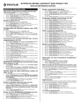
Contents
IMPORTANT SAFETY PRECAUTIONS ...........................................................................................
EasyTouch 8 or 4 System Kit Contents ............................................................................................
Accessory Equipment ......................................................................................................................
Technical Support .............................................................................................................................
iii
v
v
vi
Section 1 - EasyTouch Pool and Spa Control System Overview ............................................... 1
Operating EasyTouch .......................................................................................................................
EasyTouch Systems ........................................................................................................................
IntelliChlor® Electronic Chlorine Generator .......................................................................................
EasyTouch System Overview ............................................................................................................
EasyTouch Control Panel .............................................................................................................
EasyTouch Controls and Buttons .................................................................................................
iS4 Spa-Side Remote Controller (Optional) .......................................................................................
QuickTouch® QT4 Wireless Controller (Optional) .............................................................................
EasyTouch Indoor and Wireless Control Panel (Optional) .................................................................
EasyTouch Outdoor Control Panel Operating Modes ........................................................................
Quick Start Spa and Pool Operations ...............................................................................................
Heat your spa or pool ...................................................................................................................
Adjust your spa or pool heat settings ...........................................................................................
Switch on lights manually and synchronize light colors ................................................................
Using the Once Only timer feature ...............................................................................................
Schedule start and stop times for equipment ...............................................................................
Program your Spa or Pool ............................................................................................................
Schedules ....................................................................................................................................
Setting the Egg Timer Feature .................................................................................................
1
1
1
2
3
3
6
6
7
8
9
9
9
10
10
11
11
11
12
Section 2 - Setting up the EasyTouch System ............................................................................. 13
EasyTouch Menus ............................................................................................................................
Main Screen .....................................................................................................................................
Feature Circuits Menu ......................................................................................................................
Lights Menu .....................................................................................................................................
The Color Swim and Color Set Lighting Features ..........................................................................
Setting up Lights ..............................................................................................................................
Assign the Circuit Name and Function ........................................................................................
Setting up lights ...........................................................................................................................
Setting up IntelliBrite Light Circuits ..............................................................................................
Lights Menu .....................................................................................................................................
Modes (IntelliBrite Color light shows, Color Swim, Color Set) .......................................................
Modes (Color Swim) .....................................................................................................................
Modes (Color Set) ........................................................................................................................
Colors ..........................................................................................................................................
Hold/Recall ..................................................................................................................................
All On / All Off (Lights Menu) ........................................................................................................
Sync .............................................................................................................................................
Setting up SAM, SAL, PG2000, Color Wheel Lights ........................................................................
Config ..........................................................................................................................................
Setting up MagicStream Laminars ....................................................................................................
Heat Menu .......................................................................................................................................
Pool Temp/Src .............................................................................................................................
Spa Temp/Src ..............................................................................................................................
Delay Cancel Menu ..........................................................................................................................
Schedules Menu ..............................................................................................................................
Using the Schedule menu to program your spa or pool ................................................................
Using the Once Only feature ........................................................................................................
Using the Egg Timer (countdown) Feature ....................................................................................
Settings Menu: Clock .......................................................................................................................
15
16
17
18
18
19
19
20
20
20
20
20
21
21
21
21
21
22
22
23
25
25
25
26
27
27
29
30
31
EasyTouch Pool and Spa Control System User’s Guide
ii
Contents
(Continued)
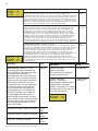
Settings Menu: IntelliFlo VS and IntelliFlo VF ...................................................................................
Settings Menu: IntelliChlor ................................................................................................................
Settings Menu: ThermalFlo ..............................................................................................................
Settings Menu: Circuit Names ..........................................................................................................
Hi-Temp/Lo-Temp Controls for Single Body System ......................................................................
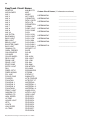
EasyTouch Circuit Names (Conplete List) .........................................................................................
Settings Menu: Circuit Functions .....................................................................................................
Freeze Protection ........................................................................................................................
Preset Circuit Function Names (Complete List) ............................................................................
Settings Menu: Custom Names ........................................................................................................
Settings Menu: Valves ......................................................................................................................
Settings Menu: 2-Speed Pump .........................................................................................................
Settings Menu: Solar ........................................................................................................................
Settings Menu: Delays .....................................................................................................................
Settings Menu: F° / C° (Fahrenheit/Celsius) .....................................................................................
Settings Menu: iS4 Spa-Side Remote Controller ...............................................................................
Settings Menu: iS10 Spa-Side Remote Controller .............................................................................
Settings Menu: iSx Pump Crtl ..........................................................................................................
Settings Menu: QuickTouch (QT4) Wireless Remote ........................................................................
Settings Menu: Man Heat (Off/On) ....................................................................................................
Settings Menu: Calibration ...............................................................................................................
Settings Menu: Erase EEPROM (Erase System Memory) ...............................................................
Settings Menu: Set Password ..........................................................................................................
Settings Menu: Wireless Addr ..........................................................................................................
Spa Side [Off/On] .............................................................................................................................
Diagnostics Menu: Software Rev ......................................................................................................
Diagnostics Menu: Bootloader Rev ...................................................................................................
Diagnostics Menu: Self Test .............................................................................................................
Diagnostics Menu: Chlorinator ..........................................................................................................
Diagnostics Menu: Water Temp ........................................................................................................
Diagnostics Menu: Solar Temp .........................................................................................................
Diagnostics Menu: Air Temp .............................................................................................................
Diagnostics Menu: Cir Name: [Off/On] ..............................................................................................
Diagnostics Menu: Reset System ....................................................................................................
Diagnostics Menu: Flash Update ......................................................................................................
32
35
36
37
37
38
39
39
40
41
41
42
42
43
44
44
45
46
47
48
48
49
49
50
51
51
51
52
53
53
53
54
54
54
54
Section 3 - Troubleshooting .......................................................................................................... 55
Frequently Asked Questions (FAQ) ..............................................................................................
EasyTouch Error Messages .........................................................................................................
Self Test Error Codes ...............................................................................................................
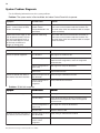
Error Code Table ......................................................................................................................
IntelliChlor Error Messages ..........................................................................................................
System Problem Diagnosis ..........................................................................................................
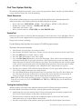
First Time System Start-Up ..........................................................................................................
Check Electronics ...................................................................................................................
System Test ............................................................................................................................
Testing the Auxiliary Relays .........................................................................................................
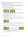
Setting up the EasyTouch wireless control panel for the first time ................................................
Synchronizing control panels .......................................................................................................
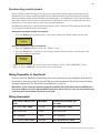
Wiring ThermalFlo to EasyTouch ......................................................................................................
55
56
56
56
57
58
61
61
61
61
62
63
63
Glossary .......................................................................................................................................... 64
EasyTouch Pool and Spa Control System User’s Guide
iii
IMPORTANT SAFETY PRECAUTIONS
Important Notice:
Attention Installer: This manual contains important information about the installation, operation and safe use of
this product. This information should be given to the owner and/or operator of this equipment.
WARNING - Before installing this product, read and follow all warning notices and instructions which are
included. Failure to follow safety warnings and instructions can result in severe injury, death, or property
damage. Call (800) 831-7133 for additional free copies of these instructions.
WARNING - Water temperature in excess of 100 degrees Fahrenheit may be hazardous to your health.
Prolonged immersion in hot water may induce hyperthermia. Hyperthermia occurs when the internal temperature
of the body reaches a level several degrees above normal body temperature of 98.6° F (37° C). The symptoms
of hyperthermia include drowsiness, lethargy, dizziness, fainting, and an increase in the internal temperature of
the body.
The effects of hyperthermia include: 1) Unawareness of impending danger. 2) Failure to perceive heat. 3) Failure
to recognize the need to leave the spa. 4) Physical inability to exit the spa. 5) Fetal damage in pregnant women.
6) Unconsciousness resulting in danger of drowning.
WARNING - To reduce the risk of injury, do not permit children to use this product unless they are closely
supervised at all times.
WARNING - The use of alcohol, drugs, or medication can greatly increase the risk of fatal
hyperthermia in hot tubs and spas.
WARNING - Control System is intended to control heaters with built-in high limit circuits ONLY. Failure to do
so may cause property damage or personal injury.
WARNING - Do not use this product to control an automatic pool cover. Swimmers may become entrapped
underneath the cover.
WARNING - For units intended for use in other than single-family dwellings, a clearly labeled emergency
switch shall be provided as part of the installation. The switch shall be readily accessible to the occupants and
shall be installed at least 10 feet (3.05 m) away, adjacent to, and within sight of, the unit.
CAUTION - Except for listed spa-side remote controls, install a minimum of five (5) feet from the inside wall
of the pool and spa.
Two Speed Pump Controls Notice (Title 20 Compliance)
Please read the following important Safety Instructions (See page 42 for pump speed setup)
When using two-speed pumps manufactured on or after January 1, 2008, the pump’s default
circulation speed MUST be set to the LOWEST SPEED, with a high speed overide capability being
for a temporary period not to exceed one normal cycle, or two hours, whichever is less.
EasyTouch Pool and Spa Control System User’s Guide
iv
IMPORTANT SAFETY PRECAUTIONS
(Continued)
General Installation Information
1. All work must be performed by a licensed electrician, and must conform to all national, state, and local
codes.
2. Install to provide drainage of compartment for electrical components.
3. If this system is used to control underwater lighting fixtures, a ground-fault circuit interrupter (GFCI)
must be provided for these fixtures. Conductors on the load side of the ground-fault circuit-interrupter
shall not occupy conduit, junction boxes or enclosures containing other conductors unless such
conductors are also protected by a ground-fault circuit-interrupter. Refer to local codes for details.
4. A terminal bar stamped
is located inside the supply terminal box. To reduce the risk of electric
shock, this terminal must be connected to the grounding means provided in the electric supply service
panel with a continuous copper wire equivalent in size to the circuit conductors supplying this
equipment (no smaller than 12 AWG or 3.3 mm). The bonding lug(s) provided on this unit are intended
to connect a minimum of one No. 8 AWG for US installation and two No. 6 AWG for Canadian
installations solid copper conductor between this unit and any metal equipment, metal enclosures or
electrical equipment, metal water pipe, or conduit within 5 feet (1.5 m) of the unit.
5. The electrical supply for this product must include a suitably rated switch or circuit breaker to open all
ungrounded supply conductors to comply with Section 422-20 of the National Electrical Code, ANSI/
NFPA 70.1987. The disconnecting means must be readily accessible to the tub occupant but installed
at least 10 ft. (3.05 m) from the inside wall of the pool.
6. Supply conductor must be sized to support all loads. Maximum supply conductor current must be 125
Amps at 125 VAC.
EasyTouch Pool and Spa Control System User’s Guide
v
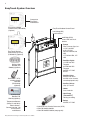
EasyTouch 8 or 4 System Kit Contents
The following items are included in the EasyTouch 8 or 4 System kit. If any items are missing, please contact
Pentair Technical Support (see page vi).
•
EasyTouch control panel (mounted in the load center)
•
EasyTouch load center enclosure
•
Two motorized valve actuators (CVA-24T P/N 263045) - Not included with single-body
system
•
Water sensor with 25 foot cable, o-ring and hose clamp (P/N 520272)
•
Air sensor with 25 foot cable (P/N 520272)
•
EasyTouch 8 and EasyTouch 4 Pool and Spa Control System User’s Guide
(this manual)
Optional Equipment
•
IntelliChlor Electronic Chlorine Generator Electrolytic Cell (model IC20 (P/N 520554) or
IC40 (P/N 520555)
•
IntelliChlor User’s Guide (P/N 520589)
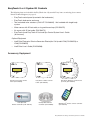
Accessory Equipment
POWER ON
EasyTouch 4 Indoor Control
Panel (P/N 520548)
iS10 Spa-Side
Remote Controller (P/N 520149)
EasyTouch 8 Indoor Control
Panel (P/N 520549)
iS4 Spa-Side Remote
Controller (P/N 520094)
EasyTouch Wireless Control Panel
(8 circuit) (P/N 520547)
QuickTouch® wireless remote controller
(P/N 520148)
EasyTouch Pool and Spa Control System User’s Guide
vi
EasyTouch Accessories
(continued)
EasyTouch Indoor Control Panel, 4 Circuits
(P/N 520548)
EasyTouch Indoor Control Panel, 8 Circuits
(P/N 520549)
EasyTouch Wireless Control Panel, 4 circuits
(P/N 520546)
EasyTouch Wireless Control Panel, 8 circuits
(P/N 520547)
iS4 Four-Function Spa-Side remote, 150 ft. cable
(P/N 520094)
iS10 Ten-Function Spa-Side remote, 150 ft. cable
(P/N 520149)
Two-Speed Three HP Relay up to three additional valve actuators
(P/N 520198)
Three HP Power Relay
(P/N 520106)
QuickTouch four-function wireless remote kit with transceiver assembly
(P/N 520148)
IntelliChlor Acid Cleaning Kit
(P/N 520670)
IntelliChlor Spacer pass-through cell for new pool start-up
(P/N 520588)
Technical Support
Contact Technical Support at:
Sanford, North Carolina (8 A.M. to 5 P.M.)
Phone: (800) 831-7133
Fax: (919) 566-8920
Moorpark, California (8 A.M. to 5 P.M.)
Phone: (800) 831-7133 (Ext. 6312)
Fax: (805) 553-5515
Web sites: visit www.pentairpool.com and www.staritepool.com
EasyTouch Pool and Spa Control System User’s Guide
1
Section 1
EasyTouch System Overview
EasyTouch® Pool and Spa Control System Overview
Welcome to the EasyTouch Pool and Spa Control system − The next generation in automatic control systems.
The EasyTouch 8 or EasyTouch 4 system allows you to automatically control all of your spa and pool daily
operations. Pool and spa service operations can be manually controlled from the EasyTouch outdoor control
panel located at the pool equipment pad. Also available is the optional Indoor Control Panel and wireless
control panel which allows automatic control of pool and spa operations from inside you home or outside
around your pool area.
The EasyTouch 8 or EasyTouch 4 system can control high voltage (120 VAC / 240 VAC) equipment,
automatic valve actuators, pumps, lighting, a conventional heater or a solar heating system and the optional
IntelliChlor salt chlorine generator.
Operating EasyTouch
The EasyTouch system is designed to automatically control your pool and spa equipment, lights and other
optional equipment. However, you can also manually control all EasyTouch system operations from the outdoor
control panel. Using the “Mode” button, the system can be switched from “Auto” mode (normal operating
mode) to “Service” mode for manual operation and service purposes. Using the outdoor control panel buttons
you can manually override any automatic settings. If required, the EasyTouch outdoor control panel can be
password protected. To access a password protected control panel, the correct four digit password must be
entered before access is granted (see page 49).
EasyTouch Systems
There are two EasyTouch system configurations available; EasyTouch 8 (auxiliary circuits) and EasyTouch 4
(auxiliary circuits). The EasyTouch system is factory configured to operate with a “shared” equipment system
or with a “single body” system. For EasyTouch 4 and EasyTouch 8 menu settings, see page 15.
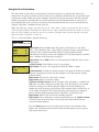
IntelliChlor® Electronic Chlorine Generator
The optional IntelliChlor salt chlorination system allows the EasyTouch system to automatically control water
sanitization by using a low concentration of salt (sodium chloride) in the pool and spa water. The IntelliChlor is
enabled from the “IntelliChlor” Settings menu (see page 35). IntelliChlor automatically converts the salt into
free chlorine which eliminate bacteria and algae in the pool and spa water. The chlorine will then revert back
to sodium chloride after killing the bacteria. The outcome of this continuous cycle, practically eliminates the
need to use sanitizing chemicals in the pool/spa water. When the pool and spa water is replenished due to
backwashing or draining, more salt may need to be added to the pool/spa water.
IntelliChlor model IC20 (P/N 520554/520556) is designed for swimming pools
up to 20,000 U.S. gallons (75,000 liters). Model IC40 (P/N 520555/520556) is
designed for swimming pools up to 40,000 U.S. gallons (151,000 liters). The
pool chlorination amounts may vary depending on number of pool occupants,
temperature, environment conditions, rainfall and other elements that might
affect the pool water.
IntelliChlor IC40 Electronic Chlorine Generator
EasyTouch Pool and Spa Control System User’s Guide
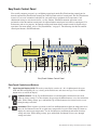
2
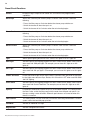
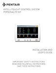
EasyTouch System Overview
Connects to
EasyTouch
motherboard
EasyTouch 8 Indoor
Control Panel (P/N 520549)
(Optional)
EasyTouch Outdoor Control Panel
Low Voltage (DC)
circuit breakers
IntelliChlor (SCG)
status LED and circuit
breaker
EasyTouch Wireless
Control Panel (8 circuit)
(P/N 520547) (Optional)
iS4 Spa-Side
Remote (P/N
520094) (Optional)
QuickTouch® (QT4)
wireless remote
Controller
(P/N 520148)
(Optional)
• Pumps
Filter, Cleaner, Spa Jet 1.5 HP 120 VAC
3 HP 277 VAC
20 FLA/120 LRA,120
VAC
17 FLA/102 LRA, 277
VAC
• Pool/Spa Lights
1.5 KW 120 VAC
Tungsten
4.8 KW 240 VAC
Tungsten
20 AMP, 277 VAC
Ballast
• Pool/Spa Valve
Suction and return.
24 VAC valve actuator,
shared equipment only
• Auxiliary Valves
(Qty. 2) A and B
• Heater
Gas or electric
iS10 Spa-Side
Remote (P/N
520149) (Optional)
Temperature Sensors
(Water, Air and Solar)
Electric Heater Connects to plug J16
on EasyTouch
motherboard
EasyTouch Pool and Spa Control System User’s Guide
• Heat Pump
(ThermalFlo®)
Heating or cooling
• Relays
25 AMP, 277 VAC
• IntelliChlor Salt Chlorine Generator (SCG)
• IC20 P/N 520554 520556
• IC40 P/N 520555/520556 (see page 26)
3
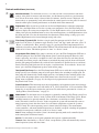
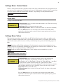
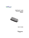
EasyTouch Control Panel
You can fully automate your pool, spa, and lighting operations from the EasyTouch outdoor control panel or
from the optional EasyTouch indoor control panel and EasyTouch wireless control panel. The EasyTouch menu
features let you create customized schedules for your pool and spa equipment, heat temperatures, and
chlorination settings to switch on and off at a set day and time. Scheduled automatic operations can be
performed at either the outdoor control panel, the optional indoor control panel and wireless control panel. For
maintenance and service purposes, the outdoor control panel button allows manual control of all pool and spa
operations. For menu options, refer to “EasyTouch Menus,” on page 15. The following describes the outdoor
control panel buttons, and LED indicators.
➁
➀
➅
➈
14
AUTO
HEATER
SPA 100°F / 95°F
AIR 70°F
MON 09:30 AM
®
➂ ➃
➄
➆
13
➇ ➉
11
13
12
EasyTouch Outdoor Control Panel
EasyTouch Controls and Buttons
➀
Liquid Crystal Display (LCD): The main system display consists of a 16 x 4 alphanumeric character
LCD with EL backlighting for easy viewing of the menu items and status messages. Press the Menu
button twice to refresh the display.
➁
Up/Down buttons: Use the Up and Down buttons to scroll through the main menu items and to
adjust or change settings. Use these buttons after pressing the Menu button to access the main menu
items. While editing settings, press and hold the Up or Down button to fast forward or fast reverse
through settings and values.
➂
Left button: When in pool or spa mode use the Left and Right button to adjust the temperature level.
Press the Left button to lower the set point water temperature. Press the Filter Pump (F) button to
display the current water temperature. Use the Left button to scroll through sub-menu selections,
setting and values. While editing settings, press and hold the Left button to fast reverse through
settings and values.
EasyTouch Pool and Spa Control System User’s Guide
4
Controls and buttons (Continued)
➃
Menu/back button: Use this button to access, save and exit from a current menu or sub-menu
MENU
settings. Also, while in a menu or sub-menu items, use this button to go back to a previous menu
level or item. If no menu activity is detected after five minutes, the main screen is displayed. All
menu settings are permanently saved and retained in the control panel even after power is removed
from the control panel. Control panel buttons are disabled while in the menu mode.
➄
Right button: When in pool or spa mode use the Left and Right button to adjust the temperature
➅
Filter Pump (F) button/LED: Switches a single speed filter pump on and off in “Pool” or “Spa”
mode. Press the Valves (V) button to toggle between “Pool” and “Spa” mode and rotate valves. If
“Heater” is enabled in the “Heat” menu (see page 25), pressing the Filter Pump button will also
enable the selected heat source (Heater/Solar LED on). The default time before the filter pump will
switch off is 12 hours. This button operates in “Auto” or “Service” mode.
level. Press the Right button to raise the set point water temperature. Press the Filter Pump (F)
button to display the current water temperature. Use the Right button to select a sub-menu item for
editing. After pressing the Menu button to access the main menu items, use the Right button to select
the menu item and access the sub-menu items for adjustment. While editing a settings, press and
hold the Right button to fast forward through settings and values.
Single-Speed Filter Pump: If the pump is currently off, press the Filter Pump button (LED on) to
switch the pump on. Press the Filter Pump button again to switch the pump off. However, if the
heater is operating, and a delay is enabled for valves, this allows the heater to cool down (heater
cool-down), then when you press the F button to switch off the pump, only the heater will turn off,
then the filter pump will automatically switch off after 10 minutes to allow the heater to cool down.
Pentair Water Pool and Spa heaters do not require a cool down time. To override the “heater cooldown,” press the Filter Pump button again to switch off the pump.
Two-Speed Filter Pump: Press the Filter Pump button (LED on) to switch the two-speed pump on
in high speed. If you switch the pump off to low speed shortly after switching it to high speed, the
filter pump will automatically remain in high speed for a few minutes before switching back to low
speed to allow the pump to prime and establish normal water flow. In order to use the “2-Speed
Pump” menu assignments (see page 42), the 2-Speed relay option must be installed in the
EasyTouch Load Center.
Freeze Protection: This function protects the pool, plumbing, and equipment against freeze damage.
If the outside air temperature sensor falls below 36° F, “Freeze Protection” is activated and the Filter
Pump relay is switched on to circulate the pool water. To enable freeze protection for a circuit, see
“Settings Menu: Circuit Function, ” on page 39.
➆
Mode button: Use this button for service purposes to manually control the EasyTouch system. Press
this button once activate “Service” mode, to allow AUX circuit buttons, Filter Pump, Valves, Heater
and Solar buttons to be operated manually. Press the button a second time to enable “Timeout”
mode. This mode is similar to “Service” mode except that the system will automatically return to
normal operation (Auto) after three hours. Press the button a third time to return the system to
“AUTO” mode. The current operating status is shown in the LCD display. The menu buttons,
remote controllers, and menu scheduled operations are disabled (except for switching off equipment
manually for emergencies) while the system is in “Service” mode.
Auto: In Auto (automatic) mode the system is in normal operating mode and is controlled by the
main control panel LCD menu features.
Service: Use this mode to service pool equipment and to operate equipment manually.
Timeout: Same functionality as “Service” mode, except that the system will automatically return to
normal operation (Auto) after three hours.
EasyTouch Pool and Spa Control System User’s Guide
5
Controls and buttons (Continued)
➇
Valves (V) - (Pool/Spa/Fill (Spillway)/Drain) button: When in normal operating mode, the
Valves (V) button is in “Pool” mode. In this mode the valves are automatically rotated so that
only the pool water is circulated through the system and the filter pump is activated. Pressing this
button once enables “Spa” mode and activates the filter pump to circulate only spa water
through the system. “Fill/Spillway” and “Drain” mode can only be used while in “Service” mode
(See Mode button for details). “Fill/Spillway” and “Drain” mode are used when cleaning the spa.
Pressing the Valves (V) button again returns the system to “Pool” mode. Note that the filter
pump will switch off while the pool/spa valves are rotating into position. The current operating
mode is shown in the LCD display. Note: The Valves button (Pool, Spa, Fill (Spillway),
Drain) button has no function in “Pool only” or “Spa only” systems. For an EasyTouch
single body system, “Pool” and “Spa” modes are Lo- Temp (Pool) and Hi-Temp (Spa)
temperature controls. For more information, see “Hi-Temp/Lo-Temp Controls for Single
Body Systems,” page 37.
➈
Aux 1 - 7 buttons/LEDs: Auxiliary output circuit buttons operate the pool and spa system valves,
lights and other equipment. These auxiliary circuits are assigned in the “Circuit Function” menu, see
page 39 for details. There are three auxiliary circuits (AUX 1- 3) on the EasyTouch 4 outdoor
control panel and seven auxiliary circuits (AUX 1- 7) on EasyTouch 8 outdoor control panel. The
Solar button can also be used for an “extra” auxiliary circuit if the Solar circuit is not being for solar
equipment. Labels can be affixed next to each auxiliary button to identify the circuit function. Labels
can be affixed over each auxiliary button to identify the circuit function. When an auxiliary circuit is
activated or the button is pressed, the LED is on. Pressing an auxiliary circuit button will activate the
corresponding circuit in either “Auto” or “Service” mode. When a circuit relay is switched on
manually, it remains on until either you switch it off manually, or the next time the relay is scheduled
to be switched off. For example, if the filter pump is scheduled to automatically run from 9:00 AM to
5:00 PM daily then the filter pump is switched on manually at 9:00 PM, it will run continuously until
the next day at 6:00 PM then switch off. The schedule will then continue from then on.
➉
Heater (Flame) button/LED: This button is only used in “Service” mode for manual heat on and off
control. The Heater LED will be on if “Heater” is enabled in the “Heat” menu setting (see page 25).
Switching the heater on automatically controls the output between a “forced off” state and a normal
automatic thermostatic control operating state. The heater will continue heating the water until the
heater’s current highest set point temperature triggers the heater sensor (approximately 104° F).
Note that the Heater button does not activate the pump. Do not activate the heater without running
the pump. The heater will not run if water flow is not detected.
Solar (Sun) button/LED and (Aux Extra): In solar mode this button is only used in “Service” mode
for manual solar heat on and off control. The Solar LED will be on if “Solar” is enabled in the
“Heat” menu setting. Solar must also be enabled in the “Solar” menu. Use the Solar button to
manually switch the heater control output between a “forced off” state and a normal automatic
thermostatic control operating state. When this button is pressed the solar relay is switched on to
activate a booster pump if installed and activates valves to rotate to divert water through solar
heating panels. If solar equipment is not being used, this button can also be used to switch the AUX
EXTRA circuit on and off.
Reset button: Press this button to reinitialize the EasyTouch outdoor control panel.
IntelliChlor status LED and circuit breaker (SCG system only): When the LED is on, it indicates
that the IntelliChlor cell is powered on. The circuit breaker opens in case the circuit is shorted or
overloaded. Press circuit breaker to reset power to the IntelliChlor.
14
Low voltage circuit breakers: Three amp circuit breakers protect the low voltage system
motherboard circuits, relays and valves.
EasyTouch Pool and Spa Control System User’s Guide
6
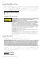
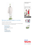
iS4 Spa-Side Remote Controller (Optional)
The iS4 Spa-Side remote controller is a doubleinsulated, waterproof device that is UL (1563)
listed for installation at the water’s edge. It is
recommended that the iS4 always be installed
above the water line of the spa wall, or in the
deck within arm’s reach of a spa occupant. The
iS4 provides remote switching of up to four
control circuits from the spa location. It is
typically used for activating spa circulation and
any three auxiliary pieces of equipment (such
as lights, jet pump, air blower, etc.). The red
status LED indicator glows steady when in Spa
mode and flashes while the spa is heating. For
more about assigning circuits to the iS4 buttons,
refer to “Settings Menu: iS4 Spa-Side Remote
controller,” on page 44. The iS4 two installation
choices are shown below:
Red power LED
indicator
1
2
3
4
4
3
2
1
Red power
LED indicator
iS4 Spa-Side
Remote Controller
(Wall or tile mount)
iS4 Spa-Side
Remote Controller
(Deck mount)
QuickTouch® QT4 Wireless Controller (Optional)
The QuickTouch QT4 wireless remote controller provides switching of up to
four circuits. You can use the QT4 wireless controller to activate the spa
circulation, and for operating three auxiliary pieces of equipment (such as lights,
jet pump, air blower, waterfall, etc.). Each of the four functions on the QT4
wireless controller has an on and an off button. For more about assigning
circuits to the QT4 buttons, refer to “Settings Menu: QuickTouch (QT4)
Wireless Remote,” on page 47.
IMPORTANT: The QT4 wireless controller may be used with wet hands,
but should never be submersed in water as this could damage the QT4. If
accidental submersion occurs, dry the QT4 out by removing battery cover
and removing battery. Position the QT4 so that water can drain out.
Reassemble when the QT4 is completely dry.
iS10 Spa-Side Remote Controller (Optional)
QuickTouch (QT4) Wireless
Remote Controller (P/N
520148)
An iS10 Spa-Side remote controller can control up to ten functions
including a spa temperature adjustment. The iS10 Spa-Side remote
controller is listed UL (1563) for use with the EasyTouch systems at the
water’s edge. Five (5) in-line buttons control up to ten (10) system
functions numbered one through five from left to right. The middle
peanut-shaped button toggles between the top and bottom row of
buttons. The iS10 includes an LED display shows the current spa water
iS10 Spa Side Remote
temperature. The spa temperature may be increased or decreased by
Controller (P/N 520149)
pressing the up or down arrow button located under the display. The
temperature display will blink while being changed. After setting the
desired temperature, the display will return to steady and show the actual temperature as it meets the set point.
The temperature set by the iS10 is only temporary. When the Spa mode is switched OFF, the temperature set
at the EasyTouch control panel will resume the next time the spa mode is activated (see “Man Heat” on page
48). The Spa Mode will automatically turn off after 24 hours. For iS10 setup and configuration information, see
page 45.
EasyTouch Pool and Spa Control System User’s Guide
7
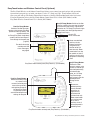
EasyTouch Indoor and Wireless Control Panel (Optional)
The EasyTouch Wireless or the Indoor Control Panel allows you to control your pool and spa daily operations
from around your pool area or inside your home. Use the “P” (Pool) and “Spa” (Pool) buttons to heat and
filter your pool and spa. The Indoor Control Panel connects to the EasyTouch motherboard in the load center.
For more information refer to the EasyTouch Indoor Control Panel User’s Guide (P/N 520616) and the
EasyTouch Wireless Control Panel User’s Guide (P/N 520688).
Spa (Hi-Temp) Button: Switches the filter
pump on, rotates valve actuator (to isolate
spa water from pool water), and switches
the heater on. Hi-Temp (EasyTouch single
body system) sets the high temperature
settings for the spa.
Circuit LED
Circuit name label
Pool (Lo-Temp) Button:
Switches the filter pump on,
rotates valve actuator (to isolate
pool water from spa water), and
switches heater on.
Lo-Temp (EasyTouch single body
system) sets the low temperature settings for the pool (see
page 37)
For details about the
control panel LCD
status messages,
see page 8
Seven user defined
auxiliary circuits.
Buttons switch the
assigned circuit
function on/off (12
hour time-out). Down
arrow button can also
be used for an “extra”
auxiliary circuit if solar
equipment is not being
used
AUTO
HEATER
SPA
100°F / 95°F
AIR
70°F
MON 09:30 AM
EasyTouch indoor control panel (EasyTouch 8) - (P/N 520549)
Pool (Lo-Temp) Button:
Switches the filter pump
on, rotates valve
actuator (to isolate pool
water from spa water),
and switches heater on.
Lo-Temp (EasyTouch
single body system)
sets the low temperature
settings for the pool.
AUTO
HEATER
SPA
95°F / 100°F
AIR
70°F
MON 09:30 AM
POWER ON
Spa (Hi-Temp) Button:
Switches the filter
pump on, rotates valve
actuator (to isolate spa
water from pool water),
and switches the
heater on. Hi-Temp
(EasyTouch single
body system) sets the
high temperature
settings for the
spa.
Seven user
defined auxiliary
circuits. Buttons
switch the assigned circuit
function on/off
(12 hour time-out)
Down arrow button
can also be used
for an “extra”
auxiliary circuit if
solar equipment is
not being used
EasyTouch wireless control panel (EasyTouch 8) - (P/N 520547)
EasyTouch Pool and Spa Control System User’s Guide
8
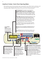
EasyTouch Outdoor Control Panel Operating Modes
The EasyTouch system can run in automatic mode or manual mode. Use the “Mode” button to switch the system
from “Auto” mode (normal operating mode) to “Service” for manual operation and service purposes. Before
operating EasyTouch, familiarize yourself with the LCD status messages and operating buttons.
AUTO (Automatic): The system is in normal operating
mode. Scheduled programs will run automatically.
HEATER: Displays the heat source (Off, Heater, Solar Prf.,
Solar) as specified in the Heater menu settings (see page
25). When the Filter Pump (F) button is pressed in “Pool” or
“Spa” mode, and heat source is enabled (Heater button LED
on).
POOL (SPA): Indicates that the Valves (V) button is in “Pool”
or “Spa” mode and the Filter Pump (F) button has been
pressed to switch on the filter pump. If this display line is
blank, it indicates no spa or pool function is active. For an
EasyTouch single body system, Hi-Temp (Spa) / Lo-Temp
(Pool) sets the temperature settings (see page 37)
95° F / 100° F: Displays the actual spa or pool water temperature (95° F) and the set point temperature (100° F) as
set in the “Heater” menu.
Left and Right
Button:
Use these buttons to
lower and raise the
current set point water
temperature level.
AIR: Displays the actual outside air temperature (70° F) as
read by the air sensor located near the EasyTouch Load
Center.
Date and Time: Displays the EasyTouch system day and
time as specified in the “Clock” menu settings (see page
31).
AUTO
HEATER
SPA
95°F / 100°F
AIR
70°F
MON 09:30 AM
®
MENU / BACK button:
Access the EasyTouch menu.
Also used to save and exit
from a current menu or submenu settings. While in menu
mode, all system control
panel buttons are disabled.
Press this button twice to
refresh the display.
Filter Pump button:
For spa operations, press the
Valves (V) button to rotate
valves into “Spa” mode, then
press the Filter (F) button to
activate the filter pump.
Press the Valves button to
toggle to “Pool” mode. The
Heater button LED will be on if
a heat source is enabled in
the Heat menu.
EasyTouch Pool and Spa Control System User’s Guide
Valves (V) button: When in normal operating
mode, the system is in “Pool” mode so that
only the pool water is circulated through the
system. Press the Valves button to enable
“Spa” mode and to rotate valves and activate
the Filter pump (Filter Pump LED on)
automatically so that only the spa water is
circulated through the system. Note that the
filter pump will switch off while the pool/spa
valves are rotating into position. “Fill/
Spillway” and “Drain” modes are used only in
“Service” mode.
9
Quick Start - Spa and Pool Operations (Shared Equipment)
The following describes how to adjust heat temperature for the spa and pool water, schedule a daily run time
for the pool/spa filter pump and control lights for shared equipment.
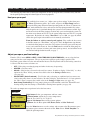
Heat your spa or pool
AUTO
HEATER First enable the heat source (see “Adjust your spa heat settings” below) then press
SPA
95°F / 100°F the Valves (V) button to enable “Spa” mode, and press the Filter Pump button to
AIR
70°F
activate the filter pump. When in normal operating mode, the Valves (V) button is in
MON 09:30 AM
“Pool” mode which turns valves and activates the filter pump automatically so that
only the pool water is circulated through the system. Press the button to enable “Spa”
mode and activate the Filter pump to circulate only spa water through the system. In
the main screen shown on left, 95°F is the current temperature and 100° F is set point
temperature. By default, the setting “Man Heat’ is set to “On” (see page 48) which
allows the spa to begin to heat whenever it is manually switched on.
From the Indoor or wireless control panel (option): First enable the heat source
in the Heat menu (see “Heat Menu,” on page 25). Press the Spa button (top button)
to switch the filter pump on, rotate the valve actuator (to isolate spa water from pool
water), and switch the heater on. Press the Pool button to switch the filter pump on,
rotate the valve actuator (to isolate pool water from spa water), and switch the heater
on. For Pool and Spa button location, see page 7.
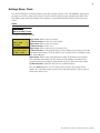
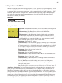
Adjust your spa or pool heat settings
From the “Heat” menu (MENU > HEAT > POOL TEMP/SRC OR SPA TEMP/SCR) you can select the heat
source and set the water temperature. The spa or pool water will heat to the settings specified. The
EasyTouch system allows for solar and conventional heaters. The EasyTouch will use the heating source that
is selected. The heat source selections are:
•
•
•
•
•
OFF - No heating even though pump and other circuits may be operating.
HEATER - Gas heater only.
SOLAR - Solar heating system to be the only heat source. In order to display “Solar Only” as a heat
option in the “Heat” menu, you must first enable solar in the Settings > Solar menu,
(see page 42).
SOLAR PREF. (Solar Preferred) - Used if solar and gas heating are combined and you want to use
solar heating only when it is most effective. In order to display “Solar Preferred” as a heat option in
the “Heat” menu, you must first enable solar in the Settings > Solar menu (see page 42).
Heat Pump (ThermalFLo): If a heat pump is being used (ThermalFlo), enable the ThermalFlo and
heating setting from the Settings > ThermalFlo > Settings menu options (see page 36).
To set the spa temperature set point and select the heat source:
Getting There
▲
MENU
HEAT
POOL Temp/Src
SPA Temp/Src
SPA
Set Temp: 85° F
Heat: Heater
Right button: Select spa temperature and heat source.
Up/Down button: Adjust the spa water temperature.
(from 40° F to 104° F or 4° C to 40° C)
Right or Left button: Move to Heat source options.
Up/Down: Set the Heat option: Off, Heater, Solar, or Solar Preferred.
Press the Menu button to save the settings and to return to the Heat menu or press
the button again to return to the main screen. Note: Select “POOL Temp/Src” to
adjust the pool temperature.
EasyTouch Pool and Spa Control System User’s Guide
10
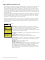
Switch on lights manually and synchronize light colors
From the Lights screen you can manually switch all lights on or off, and synchronize colored lights. Up to 12
lights can be controlled. For more information about setting up lights, including IntelliBrite® LED lights and
MagicStream® laminars, refer to “Lights Menu” on page 20.
Lights
▲
Menu
▲
Getting There
All On
To manually switch on all lights and synchronize light colors:
Modes
Colors
All On
All Off
Press the Up/Down button to select All On or All Off. Use the Sync feature with
any combination of up to 12 SAm®, SAL®, IntelliBrite, FIBERworks® lights and
MagicStream laminars to synchronize their colors before switching the lights on.
Press the Menu button to save the settings and to return to the main menu items or
press the button again to return to the main screen.
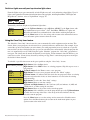
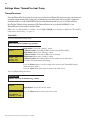
Using the Once Only timer feature
The Schedules “Once Only” timer feature lets you to automatically switch equipment on for one time. This
feature allows you to program a circuit to turn on at a particular time on a onetime basis. For example, if you
wanted the spa to be heated when you arrive home, you could program the heater to switch on at a specific
time and after you have finished using the spa you can switch the heater off manually. After the program has
run, it is automatically erased. Unlike using the regular “Schedule” program, the “Once Only” program does
not repeat. The circuit must be turned off manually or wait for the 12 hour automatic shut-off. However, you
could also reset the 12 hour factory shut-off by entering an “Egg Timer” count down program to extend past
the default 12 hours shut-off.
To schedule a specific time to turn on the spa or pool heat using the “Once Only “ feature:
Getting There
▲
MENU ▼ SCHEDULES
SPA (POOL)
SPA
0 POOL
0
AUX 1
0
AUX 2
0 SPA
0/0 Mode: None (New)
SPA
1/1
Mode: Once Only
08:00A
_
S M T W TFS
Right button: Select the Spa circuit.
Right button: Select Mode if there are existing programs. Skip this step to create a
new program.
Up/Down button: Select New to create a new program.
Right button: To create a new program and enter the “Mode” settings.
Up/Down button: 1/1 indicates that this circuit has one program. If there are existing
programs assigned to this circuit, use these buttons to view and select the existing
program settings.
Right button: To select the “Once Only” settings.
Right button: Move to start time settings.
Up/Down and Right buttons: Set the start hour (A/P) and minutes. A (AM) and
P (PM) time is set when setting the start hour.
Right button: Move to day of the week to run the program.
Right button: Select which day to run the program then press the Up/Down button
to enable the bar on top of the letter. A bar on top of the letter indicates the day
selected to run the program.
Press the Menu button to save the settings and to return to the Schedules menu
options. Press the Menu button again to return to the main menu options or press
again to return to the main screen.
EasyTouch Pool and Spa Control System User’s Guide
11
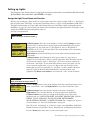
Schedule start and stop times for equipment
You can set timers (schedules) to automatically run equipment for pool filtration or turn on or off lights. Any
EasyTouch circuit can be set to switch on and off on every or any day of the week. Up to 12 total system
programs may be created for all circuits combined.
Program your Spa or Pool
You can use the “Schedule” feature to set the time and day(s) when to switch the filter pump on and rotate the
pool/spa valves into the “Pool” or “Spa” position. The heater will automatically heat the pool or spa water up
to the set point temperature as set in the “Heat” menu (see page 25). If the pool has a separate jet pump or
blower controlled by AUX 1 and/or AUX 2 , these need to be scheduled separately. If you don’t have enough
or you need to conserve auxiliary relay circuits, you can program up to eight (8) “Feature Circuits.” If a
feature circuit is scheduled, it must be turned on from the control panel “Feature Circuits” menu to allow the
schedule to run (see page 17).
Schedules
To create a schedule for your spa or pool:
Getting There
SPA
POOL
AUX 1
AUX 2
▲
MENU ▼ SCHEDULES
0
0
0
0
SPA
0/0
Mode: None (New)
SPA
1/1
Mode: Schedule
08:00A
__
_ _- 05:00P
s m t w tfs
SPA (POOL)
Right button: Select the Spa or Pool circuit. You can also select any of the available
circuits. The generic circuit names are: Spa, Pool, Aux 1-7 (EasyTouch 8),
Feature 1-8, Aux 1-3 (EasyTouch 4) and Aux Extra. Aux Extra is only available if the
Solar output (J17) plug on the EasyTouch motherboard is not being used for solar
equipment. Use the Solar button to switch the “extra” circuit on and off (see page 5).
Right button: Select Mode if there are existing programs. Skip this step to create a
new program.
Up/Down button: Select New to create a new program.
Right button: To create a new program and enter the “Mode” settings.
Up/Down button: 1/1 indicates that this circuit has one program. If there are existing
programs assigned to this circuit, use these buttons to view and select the existing
program settings.
Right button: To select the “Schedule” settings.
Right button: Move to start and stop time settings.
Up/Down and Right buttons: Set start and stop hour (A/P), minutes.
The A (AM) and P (PM) time is set when setting the start and stop hour.
Right button: Move to days of the week to run the program.
Right and Up/Down buttons: By default the program is set to run all the days of
the week. If you wish to edit which days to run the program, select the day of the
week, then press the Up/Down button to remove the bar from the top of the letter. A
bar on top of the letter indicates the day selected to run the program.
Press the Menu button to save the settings and to return to the Schedules menu
options. Press the button again to return to the main menu options or press again to
return to the main screen.
EasyTouch Pool and Spa Control System User’s Guide
12
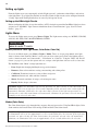
Setting the Egg Timer Feature
The “Egg Timer” feature lets you manually switch on equipment and program the system to automatically
switch off after a specified time. You can set this timer feature for other equipment such as lighting, spa, or
spa jets. Equipment can be set to be on for one minute or 24 hours. The Egg Timer program is factory set to
switch off after 12 hours. You also have the option to use the “Don’t Stop” feature to run a circuit continuously
until manually switched off.
Please note that in the event of a power failure, the Egg Timer feature will not switch the circuit back on. Use
the “Service” mode button to turn the equipment back on. Refer to “Mode button,” page 4 for details.
Note: When running the filter pump continuously during a new pool start up, it is recommended to use
the “Service” mode, which will automatically restart the filter pump in the event of a power failure.
To set the Egg Timer feature:
Getting There
SPA
POOL
AUX 1
AUX 2
0
0
0
0
SPA
0/0
Mode: None (New)
▲
MENU ▼ SCHEDULES
SPA (POOL)
Right button: Select the Spa or Pool circuit. You can also select any of the available
circuits. The generic circuit names are: Spa, Pool, Aux 1-7 (EasyTouch 8),
Feature 1-8, Aux 1-3 (EasyTouch 4) and Aux Extra. Aux Extra is only available if the
Solar output (J17) plug on the EasyTouch motherboard is not being used for solar
equipment. Use the Solar button to switch the “extra” circuit on and off (see page 5).
Right button: Select Mode if there are existing programs. Skip this step to create a
new program.
SPA
1/1
Mode: Egg Timer
Time: 05:00
Up/Down button: Select New to create a new program.
Right button: To create a new program and enter the “Mode” settings.
Up/Down button: 1/1 indicates that this circuit has one program. You create a total
of 12 programs. If there are existing programs assigned to this circuit, use these
buttons to view and select the existing program settings.
Right button: To select the “Egg Timer” settings.
Right button: Move to the time settings.
Up/Down and Right buttons: Set the hour and minutes for the program to run. The
count down time can be set from 00:01 to 23:59 and Don’t Stop. The “Don’t Stop”
feature allows the circuit to run continuously until manually switched off.
Press the Menu button to save the settings and to return to the Schedules menu
options. Press the button again to return to the main menu options or press again to
return to the main screen.
EasyTouch Pool and Spa Control System User’s Guide
13
Section 2
Setting up EasyTouch
Setting up the System for the First Time
Use the following steps if you are setting up the EasyTouch system for the first time.
Note: The following setup steps assume that the EasyTouch Load Center is installed at the equipment
pad and ready for operation. For EasyTouch Load Center installation instructions, refer to the
EasyTouch 8 and 4 Load Center Installation Guide (P/N 520583).
The recommended first time installation steps for the EasyTouch system are:
1. Set the system date and time (page 31)
Set the current date and time.
2. Assign circuit names (pages 37)
Assign the generic default circuit names for output auxiliary equipment. Rename (if necessary) and assign
circuit names to the auxiliary (AUX 1, AUX 2) connections. Note the factory set auxiliary names correspond
to the plug-in location of the relay on the EasyTouch motherboard. You can assign circuit names from the
available of circuit names. There are nearly 100 circuit names available (see page 38 for the complete list).
3. Create custom names for auxiliary circuits (page 41)
If you cannot find a circuit name that fits your application you can create up to 10 additional customized
names that can be created before assigning circuit names.
4. Assign a “Circuit Function” to a “Circuit Name” (Page 39)
Assign “Circuit Functions” to the auxiliary circuit names you created in Step 3 above. From the Circuit
Function” menu (page 39), you can assign special logic to a circuit by selecting one of the available circuit
functions. For the complete list of preset Circuit Functions see page 41. If an auxiliary circuit (AUX) is
assigned GENERIC (simple ON/OFF when the button is pushed) then nothing needs to be done.
5. Create “Feature Circuits” to conserve relays (page 17)
If you need to conserve physical auxiliary EasyTouch load center relays, there are eight (8) Feature Circuits
available that you can assign to circuit functions. Feature Circuits are manually turned on or off from the
control panel “Feature Circuits” menu.
6. Configure valve actuators (controlled by AUX circuit) (page 41)
The EasyTouch system can drive two auxiliary valve actuators for applications such as solar heating and
water features. Assign which circuits that will activate valves A and B. Auxiliary valve actuators can be
controlled by any AUX circuit. Valve A is automatically assigned to solar if “Solar” is enabled in the “Solar”
menu. Tip: Use a “Feature Circuit” to control a valve actuator (see page 17).
7. Set up optional equipment, solar, two-speed pump (page 42)
Set up additional equipment such as solar, 2-speed pump, and optional equipment if required. Set up the control
panel to operate with the optional IntelliChlor chlorine generator (see page 35). To configure EasyTouch for
special equipment:
•
•
•
•
•
•
Is solar heating available? Is solar being used for a heat pump?
What circuits will turn 2-Speed pumps to High Speed?
Is there a heat pump (ThermalFlo) being used?
Cool-down cycle for the heater - Lets you set circuits that switch the filter pump to high speed.
Do you want to delay turning off the filter pump for 10 minutes when the heater is turned off?
Do you want the spa to heat whenever the Spa button is pressed?
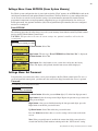
EasyTouch Pool and Spa Control System User’s Guide
14
8. Configure the heater system options (page 25)
Set the type of heat source being used (Heater, Solar, Solar Preferred). Enable heat pump (ThermalFlo) for
heating/cooling if installed.
9. Configure the iS4, iS10 spa-side remote, QuickTouch wireless remote buttons (page 44-47)
Assign circuits to the iS4, iS10 or QuickTouch remote buttons. Once you have checked that all buttons
operate properly, place labels on remote buttons. iS4 and iS10 buttons can be assigned to increase or decrease
the IntelliFlo® VS or VF pump speed using specific RPM or GPM increments.
10. Set the delays feature (page 43)
Enable the one time “delay” feature for the heater, 2-speed pump, and automatic pool cleaner.
11. Schedule on/off times for circuit (page 27 - 30)
Set times for automatic circuit activation. Up to 12 total programs can be created for all circuits combined.
One circuit can have up to a maximum of 9 programs (9/9), which leaves 3 programs that can be used by one
circuit or three separate circuits for a total of 12 programs. All user created programs are active all the time;
so check that there are not conflicting automated times.
12. Setup lighting and MagicStream laminars settings (page 23)
From the lighting menu you can control and synchronized your pool/spa, MagicStream laminars and yard
lighting.
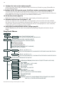
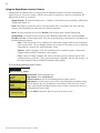
EasyTouch Menus
MAIN SCREEN
FEATURE CIR
LIGHTS
HEAT
DELAY CANCEL
SCHEDULES
FEATURE 1-8 [OFF] MANUALLY TURN A FEATURE CIRCUIT ON/OFF.
USE FEATURE CIRCUITS TO CONTROL PUMP SPEEDS AND VALVES.
MODES [6 LIGHT SHOWS, HOLD, RECALL, COLOR SWIM, COLOR SET]
COLORS [5 FIXED COLORS, HOLD, RECALL, COLOR SWIM, COLOR SET]
ALL ON (SWITCH ALL LIGHTS ON)
ALL OFF (SWITCH ALL LIGHTS OFF)
SYNC (SYNCHRONIZE COLORED LIGHTS)
MAGICSTREAM [TOGGLE THUMPER, HOLD, RESET, CHANGE MODE]
CONFIG (SETUP EIGHT LIGHT POSITIONS)
POOL TEMP/SRC
TEMP (40˚ F - 106˚ F) OR (4˚ C - 41˚ C)
HEAT (OFF/HEATER/SOLAR/SOLAR PRF) - SOLAR/SOLAR PRF MUST BE ENABLED IN "SOLAR" MENU TO DISPLAY.
SPA TEMP/SRC
TEMP (40˚ F - 106˚ F) OR (4˚ C - 41˚ C)
HEAT (OFF/HEATER/SOLAR/SOLAR PRF) - "SOLAR/SOLAR PRF" MUST BE ENABLED IN "SOLAR" MENU TO DISPLAY.
(DELAYED CANCELLED) PRESS RIGHT BUTTON TO ACTIVATE
SPA
0
POOL
0
AUX 1
0
EASYTOUCH 4 AUX 2
0
AUX 3
0
AUX 4
0
EASYTOUCH 8 AUX 5
AUX 6
0
0
MODE: ONCE ONLY
08:00A (12:00 AM - 11:59 PM -12 HOURS)
S M T W T F S (SELECT DAY OF THE WEEK TO RUN PROGRAM)
AUX 7
0
MODE: NEW / DELETE / NONE
HI-TEMP (SPA) / LO-TEMP (POOL) FOR SINGLE BODY SYSTEM (SEE SETTINGS MENU: CIRCUIT NAMES)
MODE: SCHEDULE
08:00A -- 05:00P (12:00 AM - 11:59 PM -12 HOURS)
S M T W T F S (DAYS OF THE WEEK)
MODE: EGG TIMER
TIME: 12:00 (00:00 - 23:59) / DON'T STOP
FEATURE 1-8 0
FEATURE 1 - 8
AUX EXTRA
AUX EXTRA: AUXILIARY OUTPUT (USE DOWN ARROW BUTTON TO SWITCH ON/OFF). ONLY AVAILABLE IF
SOLAR PLUG (J17) IF NOT BEING USED FOR SOLAR EQUIPMENT.
0
EasyTouch Pool and Spa Control System User’s Guide
15
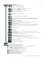
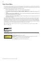
EasyTouch Menus
SETTINGS
CLOCK
(OPTIONAL)
INTELLIFLO
INTELLICHLOR 1/2 - ENABLE (YES/NO), POOL MODE: 0 - 100 % (50% default) SPA MODE: 0% (2% default)
INTELLICHLOR 2/2 - SUPER CHLR (ON/OFF), RUN HOURS (0 -72)
THERMALFLO
(OPTIONAL)
SETTINGS: ENABLE, DISABLE (NO/YES) - [HEATING, COOLING] - STATUS
CIRCUIT NAMES
CIRCUIT NAMES (1/18) - [SPA, POOL, AUX 1-7 (ET8), AUX 1-3 (ET4), FEATURE 1-8, AUX EXTRA
CIRCUIT FUNC.
CIRCUIT: (SPA [MASTER SPA], POOL [MASTER POOL], AUX 1-7 (AUX 1-3), FEATURE 1-8, AUX EXTRA - FUNCTIONS: GENERIC, MASTER SPA, MASTER POOL,
MSTR CLEANER, LIGHT, SAM LIGHT, SAL LIGHT, PHOTON GENERATOR, COLOR WHEEL, SPILLWAY, FLOOR CLEANER, INTELLIBRITE, MAGICSTREAM
FREEZE: NO/YES
CUSTOM NAMES
CSTM NAME 1/10 (ASSIGN UP TO 10 CUSTOM NAMES)
[USERNAME-01...10] (UP TO 11 ALPHANUMERIC CHARACTERS)
2-SPEED PUMP
A: [NONE, SPA, POOL, AUX 1 - 3 (ET 4) - SPA, POOL, AUX 1 - 7 (ET 8), FEATURE 1-8, AUX EXTRA, HEATER] - (USED SOLAR IF SOLAR IS ENABLED)
B: [NONE, SPA, POOL, AUX 1 - 3 (ET 4) - SPA, POOL, AUX 1 - 7 (ET 8), FEATURE 1-8, AUX EXTRA, HEATER]
2-SPEED PMP 1/4 (ASSIGN UP TO 4 CIRCUITS)
CIRCUIT (NONE, SPA, POOL, AUX 1 - 3 (ET 4) - SPA, POOL, AUX 1 - 7 (ET 8), FEATURE 1-8, AUX EXTRA, SOLAR, HEATER, POOL HEATER, SPA HEATER, FREEZE)
SOLAR
SOLAR 1/2 - ENABLE (YES/NO) - HEAT PUMP (YES/NO) - SOLAR 2/2 (TEMPREATURE DIFFERENCE) - START (3˚-9˚ (6˚ default) - RUN (2˚-5˚) (3˚ default)
DELAYS
COOL DOWN (YES/NO) - VALVES (YES/NO)
F˚ / C˚
iS4
iS10
FAHRENHEIT / CELCIUS
ASSIGN CIRCUITS 1/4
CIRCUIT - (NONE, SPA, POOL, AUX 1 - 7 (ET 8), AUX 1 - 3 (ET 4), FEATURE 1-8, AUX EXTRA, HEAT BOOST, HEAT ENABLE, PUMP INCRS, PUMP DECRS)
TOP ROW (1/5), BOTTOM ROW (1/5)
ASSIGN CIRCUITS 1/5 (NONE, SPA, POOL, AUX 1 - AUX 7 (ET 8), AUX 1 - AUX 3 (ET 4), FEATURE 1-8, AUX EXTRA, HEAT BOOST, HEAT ENABLE, PUMP INCRS, PUMP DECRS))
iSx PUMP CTRL
ASSIGN IS10 and IS4 PUMP CONTROLS [PUMP NUMBER 1/2, STEP RPM: 10-250, GPM: 1-10]
QUICK TOUCH
ASSIGN QT4 1/4 (ASSIGN UP TO 4 CIRCUITS)
CIRCUIT - (NONE, SPA, POOL, AUX 1 - AUX 7 (ET 8), AUX 1 - AUX 3 (ET 4), FEATURE 1-8, AUX EXTRA, HEAT BOOST, HEAT ENABLE)
MAN HEAT [OFF/ON]
CALIBRATION
DIAGNOSTICS
PUMP #1 - PUMP TYPE [VF, VS, NONE] - VF: FLOW (GPM), FILTERING, PRIMING, BACKWASH, VACUUM, STATUS
PUMP #2 - PUMP TYPE [VF, VS, NONE] - VS: SPEEDS (RPM), PRIMING, STATUS
INTELLICHLOR
(OPTIONAL)
VALVES
SPA SIDE [OFF/ON]
(Continued) ( )
DATE & TIME 1/2 - (MONTH/DAY/YEAR) - (DAY/HOUR/MINUTES/AM/PM)
DATE & TIMER 2/2 - DAYLIGHT SAVING: (AUTO/MANUAL)
CLOCK ADJUST 00:00 (0 TO 300) - (-300 TO -5) IN 5 SCEOND INCREMENTS
SWITCH MANUAL HEAT ON OR OFF WHEN SPA IS MANUALLY SWITCHED ON (USE RIGHT BUTTON SELECT ON/OFF)
WATER (FAHRENHEIT/CELCIUS) - AIR (FAHRENHEIT/CELCIUS) - SOLAR (FAHRENHEIT/CELCIUS) - SOLAR MUST BE ENABLED IN "HEAT" MENU TO DISPLAY
ERASE EEPROM
ERASE ALL (YES /NO) - ARE YOU SURE? (YES/NO)
SET PASSWORD
SET PASSWORD: {XXXX} 4 DIGITS - ENABLE / DISABLE [NO/YES]
WIRELESS ADDR
SET AN ADDRESS FOR EASYTOUCH WIRELESS CONTROL PANEL
ENABLE/DISABLE IS4 SPA-SIDE REMOTE
SOFTWARE REV (REVISION LEVEL FOR THE OUTDOOR AND INDOOR CONTROL PANEL)
BOOTLOADER REV (REVISION LEVEL FOR THE OUTDOOR AND INDOOR CONTROL PANEL)
SELF TEST (STATUS: TESTING (FOLLOW ON-SCREEN PROMPTS TO TEST LCD AND BUTTONS) - CODE: 0 - SEE "TROUBLESHOOTING" SECTION FOR ERROR CODES)
CHLORINATOR
SALT LEVEL: DISPLAYS CURRENT SALT LEVEL (XXXX) PPM
STATUS: OK - NO ERRORS (SUPER CHLORINATE, COM LINK ERROR, CHECK FLOW / PCB,
LOW SALT, VERY LOW SALT, HIGH CURRENT, CLEAN CELL!!, LOW VOLTAGE)
WATER TEMP (FAHRENHEIT/CELCIUS - STATUS DISPLAY ONLY)
SOLAR TEMP (FAHRENHEIT/CELCIUS - STATUS DISPLAY ONLY) - (DISPLAYS IF SOLAR IS ENABLED IN HEAT MENU)
AIR TEMP (FAHRENHEIT/CELCIUS - STATUS DISPLAY ONLY)
DISP OP CODES - DISPLAY? NO/YES (DISPLAYS TRANSMIT/RECEIVE PACKETS NUMBERS ON SCREEN)
CIR NAMES [ON/OFF] VIEW DEFAULT CIRCUIT NAMES BEFORE MODIFICATION.
RESET SYSTEM (REINITIALIZE INDOOR CONTROL PANEL - USE RIGHT BUTTON)
FLASH UPDATE (USED FOR FIRMWARE UPDATES VIA PC - PRESS MENU TO ABORT)
EasyTouch Pool and Spa Control System User’s Guide
16
EasyTouch Menus
From the EasyTouch control panel menus you can schedule everyday pool/spa, heating, filtration and cleaning.
Lights and laminars can also be scheduled to switch on and off at specific times. The “Settings” and
“Schedule” menus are typically used most often for daily spa and pool operations. The “Settings” menu is used
by the pool installer to setup installed equipment which is connected to each output relay (filter pump, auxiliary
relays, heater, valves, lights, etc.). For EasyTouch equipment installation instructions, see the EasyTouch
Installation Guide (P/N 520584).
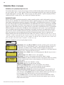
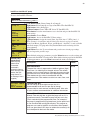
Main Screen
AUTO
SPA
AIR
MON
AUTO
POOL
AIR
MON
AUTO
HEATER
95°F / 100°F
70°F
09:30 AM
HEATER
85°F / 95°F
70°F
10:30 AM
AIR
70°F
MON 11:30 AM
The EasyTouch main screen displays the current mode of operation
(AUTO/SERVICE/TIMEOUT), heat source being used, spa (or pool) actual water
temperature (95° F), current heater set point temperature (100° F) and the current
ambient air temperature (air sensor). Degree units can be displayed in either
Fahrenheit (default) or Celsius (see page 44). If the second display line is blank and
the heat source is not displayed, there is no spa or pool function currently active. The
main screen is automatically displayed if there is no control panel menu activity for
five minutes. If there is an IntelliChlor salt chlorinator generator being used, pool and
spa sanitizer settings, and salt levels can be viewed in the Diagnostics, “Chlorinator,”
settings (see page 53).
Main Screen Description
AUTO: EasyTouch is in normal (automatic) operating mode. For information about “Service” and “Timeout”
operating modes, see page 4.
HEATER: The selected heat source as selected in the “Heat” menu (see page 25). The heat options are:
• OFF - No heating even though pump and other circuits may be operating.
• HEATER - Gas heater only.
• SOLAR ONLY - Solar heating system to be the only heat source. In order to display “Solar Pref.” on
the main screen, you must first enable solar in the “Solar” menu (see page 42).
• SOLAR PREF. - (Solar Preferred) - For when solar and gas heating are combined, and you want to
use solar heating only when it is most effective. In order to display “Solar Pref.” on the main screen,
you must first enable solar in the “Solar” menu.
SPA: “SPA” is displayed after the Valves (V) button is pressed to set in “spa” mode then the Filter (F)
button is pressed to switch the filter pump on, rotate the valve actuator (to isolate spa water from pool water),
and switch the heater on (if enabled in the “Heat” menu). Pressing the Valves (V) button alternates between
“Pool” and “Spa” mode. The temperature unit displayed on the left side is the actual water temperature (95°
F) and the set point temperature (100° F) as set in the “Heat” menu is displayed on the right side. If this
display line is blank, it indicates no spa or pool function is currently active. For Hi-Temp controls (EasyTouch
single body system), see page 37.
POOL: “POOL” is displayed after the Filter (F) button is pressed to switch the filter pump on, rotate the
valve actuator to isolate the pool water from the spa water, and switch the heater on (if enabled in the “Heat”
menu). Pressing the Valves (V) button alternates between “Pool” and “Spa” mode. The temperature unit
displayed on the left side is the actual water temperature (95° F) and the set point temperature (100° F) as set
in the “Heat” menu is displayed on the right side. If this display line is blank, it indicates no spa or pool function
is currently active. For Lo-Temp controls (EasyTouch single body system), see page 37.
AIR: Displays the actual outside ambient air temperature (70° F) as recorded by the air sensor located near
the EasyTouch load center.
DAY and TIME: The current system day and time (AM/PM). See the “Clock” menu to set the system day and
time (page 31).
EasyTouch Pool and Spa Control System User’s Guide
17
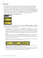
Feature Circuits Menu
There are eight (8) “Feature Circuits” that can be used to control IntelliFlo pump speeds or valves actuators
for a spa spillway. Unlike an auxiliary relay circuit, a “Feature” circuit does not connect directly to a relay.
“Feature” are turned on and off from the control panel “Feature” circuit menu.
Feature Circuits
Getting There
▲
Menu
F. Circuits
To switch a feature circuit ON or OFF:
F.
Circuits
Lights
Heat
Delay Cancel
FEATURE
FEATURE
1 [ON]
FEATURE 2 [OFF]
FEATURE 3 [OFF]
FEATURE 4 [OFF]
5 [ON]
FEATURE 6 [OFF]
FEATURE 7 [OFF]
FEATURE 8 [OFF]
Right button: Select the feature circuit to turn ON or OFF..
Up/Down buttons: Choose assigned feature circuit: FEATURE 1 - 8.
Right button: Switch the selected feature circuits ON or OFF.
When finished, press the Menu button twice to return to the main screen.
EasyTouch Pool and Spa Control System User’s Guide
18
Lights Menu
From the Lights screen you can manually switch all lights on or off, and synchronize colored lights. Up to
eight (8) lights (EasyTouch 8) or 4 lights (EasyTouch 4) can be independently controlled from the Lights
screen. Each light requires a separate auxiliary relay circuit. Up to four lights can be assigned on each
auxiliary circuit. A circuit name must be assigned to the AUX relay circuits which controls the light. Verify that
IntelliBrite, SAm and/or SAL, and/or FIBERworks have been selected in Circuit Function. If FIBERworks
lighting is being used, it also has to be set up as a Photon Generator® light source (PHOTON GENERATOR)
for the circuit controlling the light bulb, and COLOR WHEEL for the circuit controlling the color wheel. For
more information about setting up lights, see “Settings Menu: Circuit Function,” on page 39.
The Color Swim and Color Set Lighting Features
MENU
LIGHTS
▲
▲
Getting There
LIGHTS
Modes
Colors
All On
All Off
Hold
Recall
Color Swim
Color Set
The Color Swim and Color Set lighting features is selected from the LIGHTS > MODES and (COLORS)
menu. At least two (2) Pentair Water Pool and Spa®, IntelliBrite®, SAm®, SAL®, and/or FIBERworks® lighting
systems are required to use the lighting features.
•
•
•
Color Swim - Select the Color Swim feature in the MODES and COLORS menus to start lights to
transition through colors in sequence to give the appearance of colors dancing through the water. You
can adjust the delay of each light to make the colors move at different speeds using the LIGHTS >
CONFIG option. This lighting feature requires a separate relay for each light. To switch off the Color
Swim feature, select the AUX button assigned to the light circuit or select ALL OFF in the Lights
menu.
Color Set - Select the Color Set feature in the MODES and COLORS menus to switch the light on
using specific color as selected in the COLORS menu. This feature requires a separate relay for
each light. To switch off the Color Swim feature, select the AUX button assigned to the light circuit
or select ALL OFF in the Lights menu.
Configure - Select “Configure” to setup the positions of the lights the pool. Up to eight (8) lights can
be assigned a position. For more information see page 22.
All On
All Off
Sync
Configure
•
•
1-
[NONE
2[NONE
3- [NONE
4- [NONE
]
]
]
]
1 234.
[AUX 1
]
[LT.GREEN
]
[1ST POSITION ]
[DELAY 5 SECS] Sync - Select the Sync feature in the LIGHTS menu to switch on all IntelliBrite, SAm, SAL, or
FIBERworks color changing lights and synchronize their colors.
Smart Start (SS: Yes/No) - Select Smart Start in the Schedules menu (see page 27). The Smart Start
feature automatically starts changing colors when the lights are programmed to switch on. Smart
Start is used when Color Swim and IntelliBrite show modes are being used.
EasyTouch Pool and Spa Control System User’s Guide
19
Setting up Lights
The following section describes how to assign a light circuit name and function to control Pentair Water Pool and
Spa IntelliBrite, SAm and/or SAL, and/or FIBERworks lights.
Assign the Light Circuit Name and Function
The first step in setting up a light circuit is to assign a name to the relay circuit (example; AUX 3, as “Pool Light”),
then assign the name “Pool Light” circuit in the Circuit Func. menu as a “light” circuit (IntelliBrite, SAM, SAL..).
The light circuit functions are: Light, SAM, SAL, Photon Generator, Color Wheel, Spillway, MagicStream and
IntelliBrite (see page 40). After assigning the circuit name and function, the light circuit name “Pool Light” can be
setup in the CONFIG menu for light position, color etc.
To assign a circuit function:
Getting There
IntelliFlo
IntelliChlor
Circuit Names
Circuit Func.
Circuit
Circuit
Circuit
[POOL
Names
#: 1/18
: AUX 1
LIGHT
]
▲
MENU ▼ SETTINGS ▼ CIRCUIT NAMES
Up/Down buttons: Select the circuit number 1/18. Press the Up button two times
to select AUX 1 to choose this circuit for a light circuit On/Off button. The generic
circuits names are: Spa, Pool, Aux 1-7 (EasyTouch 8), Aux 1-3 (EasyTouch 4),
FEATURE 1-8 (Ft. 1-8), AuxX (Aux Extra). The circuit number (1/18) corresponds
to its assigned circuit name.
Right button: Select the EasyTouch preset circuit names and user defined custom
circuit names.
Up/Down buttons: Scroll through the list of preset names (see page 38 for a
complete list of circuit names). Select a name that describes where the light is located
or that suits the function, such as “Pool Light.” AUX 1 has now been assigned the
circuit name “Pool Light.” If you cannot find a name to match your circuit, you can
create your own custom name (see page 41). Repeat this step for all the circuit
buttons that you wish to assign names to. “Aux Extra” is only available if the Solar
output (J17) plug on the EasyTouch motherboard is not being used for solar
equipment. The Down arrow button is used to turn the “extra” circuit on and off.
Getting There
Circuit / Func. :
[POOL LIGHT
]
[INTELLIBRITE ]
Freeze: No
▲
MENU ▼ SETTINGS ▼ CIRCUIT FUNC.
Press the Menu button to return to the Settings menu. Press the Down button to and
select “Circuit Func.” Press the Right button to access the Circuit Func. menu.
Up/Down buttons: Select the already assigned circuit name “Pool Light.”
Right button: View “Circuit Functions” to assign to light circuit “Pool Light.”
Up/Down buttons: Select the type of light circuit function to use. The circuit
function names are: LIGHT, SAM LIGHT, SAL LIGHT, PHOTON GEN, COLOR
WHEEL, VALVE, SPILLWAY, FLOOR CLEANER, INITELLIBRITE,
MAGICSTREAM, GENERIC, and MSTR CLEANER. For a complete list of preset
circuit functions, see “Preset Circuit Functions” on page 40.
Note: To use the “Color Swim” or “Color Set” feature, select IntelliBrite, SAM, SAL,
Photon Generator or Color Wheel. Select “MagicStream” for MagicStream laminars.
Press the Menu button three times to return to the main screen.
EasyTouch Pool and Spa Control System User’s Guide
20
Setting up lights
From the Lights screen you can manually switch all lights on or off, synchronize colored lights, and activate
color light shows. Up to eight (EasyTouch 8) or four (EasyTouch 4) light circuits can be configured from the
“Config” light menu. Each light must have its own relay and separate circuit.
Setting up IntelliBrite Light Circuits
Before configuring the lights, be sure the auxiliary (AUX) circuits that control the IntelliBrite lights have been
assigned as an “IntelliBrite” light. For more information about “Circuit Functions” (page 39) and “Circuit
Names,” (page 37).
Lights Menu
To access the Lights menu screen, press Menu > Lights. The Lights menu settings are: MODES, COLORS,
ALL ON, ALL OFF, SYNC, MAGICSTREAM, CONFIG:
MENU
LIGHTS
▲
▲
Getting There
LIGHTS
Modes (IntelliBrite Color light shows, Color Swim, Color Set)
To access the Modes menu, press Menu > Lights > Modes. There are six pre-programmed color light
shows to choose from. From the “Modes” screen you can select various preset show color lighting effects,
such as “American mode” and “Sunset mode”, “Color Swim” or “Color Set.” Using the “Hold” and “Recall”
feature (see page 21) you can also capture and save a unique color light show effect to recall at a later time.
The IntelliBrite color “Mode” settings light shows are:
•
Party: Rapid color changing building the energy and excitement
•
Romance: Slow color transitions creating a mesmerizing and calming effect
•
Caribbean: Transitions between a variety of blues and greens
•
American: Patriotic red, white and blue transition
•
Sunset: Dramatic transitions of orange, red and magenta tones
•
Royalty: Richer, deeper, color tones
IntelliBrite Light: If the IntelliBrite light was not previously on, after selecting a color show mode, no
illumination will occur for up to ten (10) seconds (depending on the selection), then a white light will
momentarily illuminate, followed by the color show mode selection. If the light was previously on,
selecting the a color show mode button will momentarily illuminate the previously selected color before
changing to the selected color show.
Modes (Color Swim)
The Color Swim feature cycles through white, magenta, blue and green colors. Using IntelliBrite lights, Color
Swim emulates the Pentair Water Pool and Spa SAM and SAL Color Swim feature.
IntelliBrite Light Color Swim/Color Set: If the light was not previously on, after selecting Color Swim,
no illumination will occur for approximately six (6) seconds followed by the selection. If the light was
previously on, after selecting the Color Swim feature, the previously selected color will momentarily
illuminate, no illumination will occur for approximately six (6) seconds followed by the selection.
EasyTouch Pool and Spa Control System User’s Guide
21
Setting up lights
(Continued)
Modes (Color Set)
The “Color Set” feature allows any combination of up to eight (EasyTouch 8) or four (EasyTouch 4)
IntelliBrite lights, and SAm, SAL and or Fiberworks lighting to be preset to specific colors. Fixed light colors
are selected and activated from the Colors screen.
IntelliBrite Light: If the light was not previously on, after selecting the fixed colored light, no
illumination will occur for approximately six (6) seconds followed by the selection. If the light was
previously on, after selecting the colored light, the previously selected color will momentarily illuminate,
no illumination will occur for approximately six (6) seconds followed by the selection.
Colors
Choose any one of the five fixed colors to create a spectacular underwater lighting effect. The fixed colors
are: Blue, Green, Red, White and Magenta. You can switch each fixed colored light on or off from the
Colors screen.
IntelliBrite Light: If the light was not previously on, after selecting a fixed colored light, no illumination
will occur for up to ten (10) seconds (depending on the selection), then a white light will momentarily
illuminate, followed by the color selection. If the light was previously on, selecting the a color button
will momentarily illuminate the previously selected color before changing to the selected color.
To select a fixed color press: Menu > Lights > Modes > Colors:
Blue
Green
Red
White
Green
Red
White
Magenta
Magenta
Hold/Recall
Up/Down buttons: Choose a color for the light.
Right button: Switch the selected colored light ON. To switch the light off, go to
the main Lights menu and select All Off, or press the AUX button assigned to the
light. The AUX button will also switch the light on.
Press the Menu button three times to return main menu.
WARNING - IntelliBrite Lights: During the off/on switching process,
before the selected color is displayed, no illumination will occur. This
operating mode is normal during the switching process. During this period
the pool and spa will be dark and precautions should be taken to avoid
unforeseen accidents. Failure to observe this warning may result in
serious injury or death to pool and spa users.
Select Hold and Recall from the “Modes” or “Color” screen to capture and save a unique color effect and
recall it at a later time. For example, while a light show (Romance Mode) is active, select “Hold” to save the
exact colors that are being displayed, then later, to recall the exact color effect, select “Recall.”
Note: After selecting Hold or Recall, no illumination will occur for up to 10 seconds, then a white light
will momentarily illuminate, followed by the saved color.
All On / All Off (Lights Menu)
Select All On or All Off from the Lights screen to manually switch all lights on or off, including any
MagicStream laminar circuits. Press the control panel auxiliary button (AuxX) assigned to a light circuit will
also switch a light on or off.
Sync
Select Sync from the “Lights” screen to synchronize colors for all IntelliBrite, SAm, SAL and FIBERworks
color changing lights.
EasyTouch Pool and Spa Control System User’s Guide
22
Setting up lights (Continued)
Config
From the “Config” screen you can setup the IntelliBrite light position, and specify the color of each pool and
spa light. Any combination of up to eight (EasyTouch 8) or four (EasyTouch 4) IntelliBrite lights, SAM, SAL
and or Fiberworks lights can be preset for specific colors and position when using the “Color Swim” and
“Color Set” feature. Fixed light color are selected and activated from the Colors screen. Note: The “Config”
menu settings do not apply to the MagicStream laminars.
To select configure a light position and color: Menu > Lights > Config:
]
]
]
]
5678-
]
]
]
]
1- [POOL
2- [SPA
3- [BACK YARD
4- [AUX 4
[NONE
[NONE
[NONE
[NONE
[ AUX 4
[ LAVENDER
[ 1ST POSITION
[ DELAY 5 SECS
]
]
]
]
Up/Down buttons: Choose the light circuit (1-8) to configure. Select an available
auxiliary circuit (NONE). For more about assigning an auxiliary circuit to a light,
see “Circuit Functions (page 39) and “Circuit Names” (page 37). EasyTouch 8
supports up to eight (8) auxiliary circuits, EasyTouch 4 supports up to four (4)
auxiliary circuits.
Right button: Select the light to setup.
Up/Down buttons: Select the light circuit.
Right button: Move to the light color selection.
Up/Down buttons: Select the light color (Blue, Cyan, Green, Lt. Green,
White, Lt. Magenta, Magenta, Lavender).
Right button: Move to the light position selection.
Up/Down buttons: Select the light position. A light can be assigned to any
position from 1 through 12. To ensure that the “Color Swim” and “Color Set”
lighting feature color effects are correct, set the position of the light according to
where it’s located in the pool or spa. Position 1 will lead all the other lights in the
color changing sequence. Position 2 follows Position 1 and so on. There are 12
position to choose from. More than one light may be assigned to the same position
number so that their colors may be synchronized. For example, to make the colors
swim right to left, make your right most light Position 1. You may need to go
back to and scroll through your lights to find the right most light, and set it as
Position 1.
Right button: Move to the light delay selection. The Delay time between two or
more lights can be set from 0 to 60 seconds. Use a higher delay time for lights
spread further apart. Try five seconds for all lights and observe the effect. Use
different time settings to achieve unique lighting moods and effects.
Press the Menu button to setup other lights or press Menu button four times
to return main screen.
Setting up SAM, SAL, PG2000, Color Wheel Lights
Before using the lighting feature “Color Swim” or “Color Set” with SAM or SAL lights, make sure the AUX
relay circuits which control the lights have been assigned as “light” circuit and that the name (AUX 1, AUX 2)
has been changed to best fit the light being used. Verify that SAm and/or SAL, and/or FIBERworks have been
assigned in “Circuit Functions” as SAM or SAL light. If FIBERworks lighting is incorporated, it also has to be
set up as a “PHOTON GENERATOR” light for the circuit controlling the light bulb, and COLOR WHEEL for
the circuit controlling the color wheel it self. The circuit light “functions” are: Light, SAM, SAL, Photon
Generator, Color Wheel, and IntelliBrite, see page 40 for a more information.
EasyTouch Pool and Spa Control System User’s Guide
23
Setting up MagicStream Laminars
The MagicStream® Laminar provide a clear, turbulence-free stream of water that is lit with a fiber optic cable,
or an LED light for a dazzling nighttime effect. The 12 VAC powered LED light can generate a series of
multicolored light shows, or can be set to display a continuous, single color. If desired, the built-in solenoid
“thumper” can create a random “wrinkle,” in the Laminar’s stream, causing it to display a brilliant spot of light
that moves along the stream’s arc. The light enhancer can be adjusted to maximize the light in the arc.
Up to twelve (12) MagicStream Laminar circuits can be displayed on the main Lights screen, assuming each
laminar has its own relay and separate circuit.. From the Lights screen you can activate the MagicStream
laminars (changing color modes, turn Thumper on/off, Hold and Reset). For more information, see the
MagicStream® Laminar Installation Guide, P/N 520969.
Setting up MagicStream Laminar LED Lights
To setup MagicStream laminar circuits, first assign each laminar auxiliary relay circuit a circuit name (see
“Circuit Names” page 37, then assigned the laminar relay circuit name to “MAGICSTREAM” in the circuit
functions menu (Circuit Func.).
To setup the MagicStream laminar circuit names and function:
Getting There
IntelliFlo
IntelliChlor
Circuit Names
Circuit Func.
Circuit Names
Circuit #: 1/18
Circuit : AUX 1
[STREAM
]
Getting There
▲
MENU ▼ SETTINGS ▼ CIRCUIT FUNC.
Circuit / Func. :
[STREAM
]
[MAGICSTREAM ]
Freeze: Yes
▲
MENU ▼ SETTINGS ▼ CIRCUIT NAMES
Up/Down buttons: Select the circuit number 1/18. Press the Up button two times
to select AUX 1 to choose this circuit for the MagicStream laminar circuit On/Off
button. The generic circuits names are: Spa, Pool, Aux 1-7 (EasyTouch 8), Aux 1-3
(EasyTouch 4), FEATURE 1-8 (Ft. 1-8), AuxX (Aux Extra).
The circuit number (1/18) corresponds to its assigned circuit name.
Right button: Select the EasyTouch preset circuit names and user defined custom
circuit names.
Up/Down buttons: Scroll through the list of preset names (see page 38 for a
complete list of circuit names). Select a name that describes where the MagicStream
laminar is located or that suits the function, such as “Stream.” AUX 1 has now been
assigned the circuit name “Stream.” for the first MagicStream laminar. Repeat this
step for the next laminar circuit. If you cannot find a name to match your circuit, you
can create your own custom name (see page 41). “Aux Extra” is only available if the
Solar output (J17) plug on the EasyTouch motherboard is not being used for solar
equipment. The Down arrow button is used to turn the “extra” circuit on and off.
Press the Menu button to return to the Settings menu. Press the Down button to and
select “Circuit Func.” Press the Right button to access the Circuit Func. menu.
Up/Down buttons: Select the already assigned circuit name “Stream.”
Right button: View the “Circuit Functions” to assign to laminar circuit “Stream.”
Up/Down buttons: Select the type of circuit function to use, in this case select
“MAGICSTREAM.” The circuit function names are: LIGHT, SAM LIGHT, SAL
LIGHT, PHOTON GEN, COLOR WHEEL, VALVE, SPILLWAY, FLOOR
CLEANER, INITELLIBRITE, MAGICSTREAM, GENERIC, and MSTR
CLEANER. For a complete list of preset circuit functions, see “Preset Circuit
Functions” on page 40.
Right button/ Up Button: Turn “Freeze” protection ON.
Press the Menu button three times to return to the main screen. Continue on next page...
EasyTouch Pool and Spa Control System User’s Guide
24
Using the MagicStream Laminar Features
The MagicStream laminar features are displayed in the MagicStream menu. Each time a MagicStream
laminar feature is activated, it resumes with the same features in operation as when last switched off. The
MagicStream features are as follows:
Toggle Thumper - Pressing this button creates a "wrinkle" in the laminar stream, producing a brilliant spot
of light in the laminar arc.
Hold - Select Hold to capture the current color effect while colors are changing. The colors will stop
changing. Selecting Hold again will resume the color changing mode.
Reset - Pressing this button reverts to the Random color changing mode with the Thumper ON.
Change Mode - Pressing this button (each successive OFF/ON combination) will cycle through Sync,
Random and Party. Color changing mode - The color of the light changes automatically, according to one
the following three programs:
Sync - Colors will change at ten second intervals. In this mode, multiple laminars will synchronize
colors together. Note: To sync multiple laminars (two or more AUX circuits), be sure to define the
“MagicStream” circuits in the “Circuit Functions” menu.
Random - Colors will change at ten (10) second intervals in a random sequence. In this mode,
multiple laminars will NOT synchronize colors together.
Party - Colors will change randomly and slowly at first, then speed up, until the sequence ends
with quick flashes and strobes. The sequence then repeats, beginning with the slow changes. In
this mode, multiple Laminars will NOT synchronize colors together.
To access the MagicStream laminar features:
MENU
LIGHTS
▲
▲
Getting There
LIGHTS
All On
All Off
Sync
MagicStream
Toggle Thumper
Hold
Reset
Change Mode
Change Mode
Down button: Choose MagicStream.
Right button: Select MagicStream.
Up/Down button: Select the desired MagicStream laminar features.
Right button: Use this button to activate the selected MagicStream laminar feature.
After the button is pressed, the following screen displays the name of the selected
feature (indicating that the MagicStream feature has been activated) then returns to
the MagicStream feature menu.
Press the Menu button three times to return to the main screen.
EasyTouch Pool and Spa Control System User’s Guide
25
Heat Menu
Use the heat menu settings to specify the set point temperature and select the heat source for the pool and spa
water. The water will begin to heat whenever the heater is manually switched on, (by pressing the Valves (V)
button (on the Outdoor Control Panel) or the “Pool” or “Spa” button on the Indoor Control Panel), even if the
heater is set to off. The spa will also begin to heat when switched on by the optional iS4/iS10 Spa-Side remote,
or EasyTouch wireless remote. The EasyTouch system allows for solar and conventional heaters. The
EasyTouch will use the heating source that is selected. The heat source selections are:
•
•
•
•
OFF - No heating even though pump and other circuits may be operating.
HEATER - Gas heater only. Use the Heater button to automatically switch the heater on which
controls the output between a “forced off” state and a normal, automatic thermostatic control
operating state. The heater will continue heating the water until the heater’s current highest set point
temperature triggers the heater sensor (approximately 104° F or 40° C). Note that the Heater button
on the control panel does not activate the pump. Do not activate the heater without running the pump.
The heater will not run if water flow is not detected.
SOLAR ONLY - Solar heating system to be the only heat source. In order to display “Solar Pref.” on
the main screen, you must first enable solar in the “Solar” menu (see page 42).
SOLAR PREF. (Solar Preferred) - Solar and gas heating systems are installed, and you want to use
solar heating only when it is most effective. In order to display “Solar Pref.” on the main screen, you
must first enable solar in the “Solar” menu. To set the spa temperature and select the heat source:
Pool Temp/Src
Getting There
▲
MENU
HEAT
To set the pool temperature and select the heat source:
POOL Temp/Src
SPA Temp/Src
POOL
Temp: 72° F
Heat: Off
Right button: Select pool temperature and heater options.
Up/Down button: Set the pool temperature (from 40° F to 104° F).
Right or Left button: Move to Heater option.
Up/Down: Set Heater option: Off, Heater, Solar, or Solar Preferred.
Press the Menu button to save the settings and to return to the previous menu or
press the button again to return to the main screen.
Spa Temp/Src
To set the spa temperature and select the heat source:
POOL Temp/Src
SPA Temp/Src
SPA
Temp: 85° F
Heat: Off
Right button: Select spa temperature and heater options.
Up/Down button: Set the spa temperature (from 40° F to 104° F or 4° C to 40° C).
Right or Left button: Move to Heater option.
Up/Down: Set Heater option: Off, Heater, Solar, or Solar Preferred.
Press the Menu button to save the settings and to return to the Heat menu or press
the button again to return to the main screen.
Note: For an EasyTouch single body system, “Pool” and “Spa” modes are Lo- Temp (Pool) and
Hi-Temp (Spa) temperature controls. For more information, see “Hi-Temp/Lo-Temp Controls for Single
Body Systems,” on page 37.
EasyTouch Pool and Spa Control System User’s Guide
26
Delay Cancel Menu
Use the Delay Cancel feature for service or testing purposes. For convenience, on a onetime basis, the Delay
Cancel feature will cancel the following safety delays. Please note, generally there is no need to cancel any of
the following delays except for servicing or testing the system.
•
•
Heater Cool-Down Delay Cancel: Shuts Filter Pump off immediately.
2-Speed Filter Pump five-minute START on HIGH SPEED Delay Cancel: Shifts pump to low
speed.
• Automatic Pool Cleaner START Delay: Starts Cleaner Pump immediately, without normal delay in
which the filter pump first runs for 5 minutes.
• Automatic Pool Cleaner SOLAR Delay: Allows Cleaner Pump to run even though solar delay has
shut it off for 5 minutes.
Some heaters require a cool-down cycle before being switched off. This can be setup in the menu to run the
filter pump an additional ten minutes to dissipate residual heat built up inside the heater combustion chamber.
The Delay Cancel feature is mainly for use by service technicians when it’s necessary to shut the filter pump
off immediately, and know the heater has not been running. Heaters manufactured by Pentair Water Pool and
Spa do not require this cool-down period and do not need the delay to be set up.
Note: For Information about assigning delays to the pool and spa valves, refer to “Settings Menu:
Delays” on page 43.
Getting There
▲
MENU ▼ DELAY CANCEL
Delay Cancel
To activate Delay Cancel:
F. Circuits
Lights
Heat
Delay Cancel
Up/Down button: Select Delay Cancel.
Right button: Use this button activate Delay Cancel for one time only. “Delay
Cancelled” is displayed after pressing the Right button.
Press the Menu button to return to the main screen.
EasyTouch Pool and Spa Control System User’s Guide
27
Schedules Menu
Use the Schedules menu to create programs to schedule start and stop times to automatically run equipment,
such as pumps and lights. Any circuit can be programmed to switch on and off at a specific time on every or
any specific day of the week. The number of programs that can be created for circuits are as follows:
•
•
Up to 12 total programs can be created for all circuits combined.
One circuit can have up to a maximum of 9 programs (9/9), which leaves 3 programs that can be
used by one circuit or three separate circuits for a total of 12 programs.
Using the Schedules menu
Use the Schedules menu features to program operating schedules for the pool, spa and auxiliary circuits:
Getting There
SPA
▲
MENU ▼ SCHEDULES
SPA
Choose the circuit to program
0
0
0
0
SPA
Mode: None
0/0
Create a new program
SPA
Mode: New
0/0
The current number of programs for each circuit is indicated opposite to the circuit
name. 0/0 indicates no programs assigned to this circuit.
Right button: To move to the “Mode” selection.
Up/Down button: Select New to create a new program. Use “None” when a circuit
has existing programs and you wish to exit the “Mode” selections without modifying
the existing programs.
POOL
AUX 1
AUX 2
SPA
1/1
Mode: Schedule
_08:00A - 05:00P
smtwtfs SS: N
SPA
1/1
Mode: Egg Timer
Timer: 12:00
SPA
1/1
Mode: Once Only
_08:00A
_ _
s m t w tfs
SPA
Mode: New
1/1 SPA
Mode: None
1/1
SPA
1/1
Mode: Delete
Up/Down button: Select the generic circuit name to program: Spa, Pool, Aux 1-7,
Feature 1- 8, Aux 1-3 and Aux Extra. Aux Extra is only available if the Solar output is
not being used. See Solar button on page 5 for details.
The current number of programs for each circuit is displayed opposite the circuit
name. A circuit can have up to 9 programs (9/9). Three additional programs can be
assigned to another circuit or three separate circuits for a maximum of 12 programs.
Choose the type (Mode) of program to run
After selecting “New” the current program number (1/1) for this circuit is displayed.
Right button: To move to the “Mode” selections.
Up/Down button: Choose the program to run: Schedule, Egg Timer, Once Only,
New, Delete, and None. If there are existing programs assigned to this circuit, use
these buttons to view and select the existing program settings.
Mode Selection:
Schedule: Set start, stop times and the day(s) of the week to automatically switch
pool/spa circuits on or off. Default run time for the “Schedule” feature is 8:00 AM to
5:00 PM. If you program the start and stop times the same the schedule is will run for
24 hours. Note: SS: N (Smart Start) is displayed if a light circuit is being
scheduled (see page 18).
Egg Timer: A one time program that switches on a function at a specific time, and
counts down the preset time to the switch off the function. After the “Egg Timer”
schedule has finished, the system can be operated in manual mode. The “DON'T
STOP” option allows a circuit to run continuously until its switched off manually.
Once Only: Schedule a circuit to switch on at a particular time on a onetime basis.
New: press the Right button to create a new program.
Delete: Select the program and press the Right button to delete it.
None: Press the Right button to exit the “Mode” selections without modifying the
program.
EasyTouch Pool and Spa Control System User’s Guide
28
Schedules Menu (Continued)
Schedule your spa/pool pump to turn on
Use the Schedule feature to set the time and day(s) when to switch the filter pump on and rotate the pool or
spa valves into the “Spa” or “Pool” position. The heater will automatically heat the spa or pool water up to the
set point temperature as set in the “Heat” menu (see page 25). If the pool has a separate jet pump or blower
controlled by AUX 1 and/or AUX 2 , these need to be scheduled separately.
Schedule Example
When a circuit relay is switched on manually, it remains on until you either switch it off manually, or the next
time the relay is scheduled to be switched off. For example, if the filter pump or any circuit is scheduled to run
from 9AM to 4 PM and the programmed schedule is turned OFF at 1:00 PM and then turned on at 1:10 PM,
the circuit will turn OFF at its programmed OFF time of 4:00 PM. But if the circuit is turned on after 4:00 PM,
the factory set Egg Timer of 12 hours is now engaged. So if the circuit was turned on at 6:00 PM that circuit
will turn off at 6:00 AM (12 hours later). If the circuit was turned ON at 5:00 PM and because a programmed
OFF time had been set to turn off at 4:00 PM, the circuit would operate for 11 hours. A spa or pool program
can be overridden using the Spa button or Pool button to switch the circuit on. If you program the start and
stop times the same, the schedule will run for 24 hours if scheduled to run for one day. In “Service” mode, a
pool or spa program can be overridden using the Filter (F) button and pool/spa Valves (V) button on the
outdoor control panel in the EasyTouch load center. Note: The following example describes how to use the
“Schedule” feature to program the spa circuit to switch the filter pump on and rotate the valves into the
“Spa” position and switch the heater on. This example can also be used to program when to filter and
heat your pool, and switch light or auxiliary circuits on or off.
To create a schedule for your spa or pool pump to turn on:
Getting There
SPA
POOL
AUX 1
AUX2
▲
MENU ▼ SCHEDULES
SPA
0
0
0
0
SPA
0/0
Mode: None (New)
SPA
1/1
Mode: Schedule
_08:00A_ - 05:00P
S M T W TFS
Right button: Select the SPA or POOL circuit. The available generic circuit names
are: Spa, Pool, Aux 1-7 (EasyTouch 8), Aux 1-3 (EasyTouch 4), Feature Circuit 1-8
and Aux Extra. Aux Extra is only available if the Solar output (J17) plug on the
EasyTouch motherboard is not being used for solar equipment. Use the Solar button to
switch the “extra” circuit on and off (see page 5).
Right button: Select Mode if there are existing programs. Skip this step to create a
new program.
Up/Down button: Select New to create a new program.
Right button: To create a new program and enter the “Mode” settings.
Up/Down button: 1/1 indicates that this circuit has one program. If there are existing
programs assigned to this circuit, use these buttons to view and select the existing
program settings.
Right button: To select the “Schedule” settings.
Right button: Move to start and stop time settings.
Up/Down and Right buttons: Set start and stop hour (A/P), minutes.
The A (AM) and P (PM) time is set when setting the start and stop hour.
Right button: Move to days of the week to run the program.
Right and Up/Down buttons: By default the program is set to run all the days of
the week. If you wish to edit which days to run the program, select the day of the
week, then press the Up/Down button to remove the bar from the top of the letter. A
bar on top of the letter indicates the day selected to run the program.
Press the Menu button to save the settings and to return to the Schedules menu
options. Press the button again to return to the main menu options or press again to
return to the main screen.
EasyTouch Pool and Spa Control System User’s Guide
29
Using the Once Only feature
The “Once Only” feature allows you to program a circuit to switch on at a particular time and day on a
onetime basis. A typical use for this feature is to have the spa and heater switch on before you get home from
work for one evening. Unlike the regular “Schedule” timer, this feature does not repeat. After this event has
finished, the program is automatically erased. The circuit must be switched off manually or wait for the 12
hour automatic shut off. If you wish to override the 12 hour default shut-off time you can extend the time by
using the “Egg Timer” countdown feature (page 30).
Note: The following example describes how use the “Once Only” feature to program the spa circuit to
switch the filter pump on and rotate the valves into the “Spa” position and switch the heater on for one
time only. This example can also be used if you wanted to program when to filter and heat your pool,
and switch light or auxiliary circuits on.
The set a “Once Only Timer” program for the spa:
Getting There
SPA
POOL
AUX1
AUX2
▲
MENU ▼ SCHEDULES
0
0
0
0
SPA
0/0
Mode: None (New)
SPA
SPA
1/1
Mode: Once Only
08:00A_
S M T W TFS
Right button: Select the Spa circuit. The generic circuit names are: Spa, Pool,
Aux 1-7 (EasyTouch 8), Aux 1-3 (EasyTouch 4), Feature Circuit 1-8, and Aux Extra.
Aux Extra is only available if the Solar output (J17) plug on the EasyTouch
motherboard is not being used for solar equipment. Use the Solar button to switch the
“extra” auxiliary circuit on and off (see page 5).
Right button: Select Mode if there are existing programs. Skip this step to create a
new program.
Up/Down button: Select New to create a new program.
Right button: To create a new program and enter the “Mode” settings.
Up/Down button: 1/1 indicates that this circuit has one program. If there are existing
programs assigned to this circuit, use these buttons to view and select the existing
program settings.
Right button: To select the “Once Only” settings.
Right button: Move to start time settings.
Up/Down and Right buttons: Set the start hour (A/P) and minutes. A (AM) and P
(PM) time is set when setting the start hour. Note: if the Start Time is set to an hour
which has already passed, then the program will be executed the following day.
Another day of the week may also be chosen. The stop time will be 12 hours later, or
can be turned off manually. The 12-hour shut off can be changed to any length of
time by entering another program using the “Egg Timer” program (page 30).
Right button: Move to day of the week to run the program.
Right button: Select which day to run the program then press the Up/Down button
to enable the bar on top of the letter. A bar on top of the letter indicates the day
selected to run the program.
Press the Menu button to save the settings and to return to the Schedules menu
options. Press the button again to return to the main menu options or press again to
return to the main screen.
EasyTouch Pool and Spa Control System User’s Guide
30
Using the Egg Timer (countdown) Feature
The “Egg Timer” feature allows you switch off a circuit automatically after a specified time. The time period
is from one minute to 24 hours or run continuously. The “Egg Timer” (countdown) feature is useful for
switching off lighting and spa therapy jets. For example, a jet pump can be setup to switch off in 15 minutes,
even if you switch it on using the iS4 or iS10 Spa-Side remote control or whenever you switch your spa on,
you would like it to automatically switch it off in two hours. All Egg Timer programs are factory set to switch
off after 12 hours. You also have the option to use the “Don’t Stop” feature to run a circuit continuously until
manually switched off.
In the event of a power failure, the “Egg Timer” feature will not switch the circuit back on. Use the “Service”
mode to turn the equipment back on. Refer to “Mode button,” page 4 for more information. For running the
filter pump continuously during new pool start up, it is recommended to use the “Service” mode, which will
automatically restart the filter pump in the event of a power failure.
The following example describes how use the “Once Only” feature to program the spa circuit to switch the
filter pump on and rotate the valves into the “Spa” position and switch the heater on for one time only. This
example can also be used if you wanted to program when to filter and heat your pool, and switch light or
auxiliary circuits on.
To set the Egg Timer feature:
Getting There
▲
MENU ▼ SCHEDULES
SPA
0 POOL
0
AUX 1
0
AUX 2
0 SPA
0/0 Mode: None (New)
Right button: Select the Spa circuit. The generic circuit names are: Spa, Pool,
Aux 1-7, (EasyTouch 8), Aux 1-3, (EasyTouch 4), Feature Circuit 1-8 and Aux Extra.
Aux Extra is only available if the Solar output (J17) plug on the EasyTouch
motherboard is not being used for solar equipment. Use the Solar button to switch the
“extra” auxiliary circuit on and off (see page 5).
SPA
1/1
Mode: Egg Timer
Time: 05:00
Right button: Select Mode if there are existing programs. Skip this step to create a
new program.
Up/Down button: Select New to create a new program.
Right button: To create a new program and enter the “Mode” settings.
SPA
Up/Down button: 1/1 indicates that this circuit has one program. If there are existing
programs assigned to this circuit, use these buttons to view and select the existing
program settings.
Right button: To select the “Egg Timer” settings.
Right button: Move to the time settings.
Up/Down and Right buttons: Set the hour and minutes for the program to run. The
count down time can be set from 00:01 to 23:59 and Don’t Stop. The “Don’t Stop”
feature allows the circuit to run continuously until manually switched off.
Press the Menu button to save the settings and to return to the Schedules menu
options. Press the button again to return to the main menu options or press again to
return to the main screen.
EasyTouch Pool and Spa Control System User’s Guide
31
Settings Menu: Clock
Use the Clock menu to set the EasyTouch system date and time. The day, time and AM/PM is displayed on
the main screen. The system clock settings are used for the EasyTouch system scheduled operations. The
EasyTouch system clock will continue to run if power is removed from the EasyTouch system at the load
center.
Clock
Getting There
▲
MENU ▼ SETTINGS
CLOCK
To set the system date and time:
Date & Time
1/2
JAN 12 2009
09:20 AM
Date & Time
2/2
DayLt Sav: Auto
Clk Adj: 00:00
Right button: Move to the day setting.
Up/Down buttons: Set the day of the month.
Right button: Move to the year setting.
Up/Down buttons: Set the year.
Right button: Move to the next set of settings (2/2).
Up/Down buttons: Set Daylight Savings to Auto or Manual. Auto keep track of the
semi annual time changes. If you do not live in an area that observes daylight savings
time, choose Manual.
Right button: Move to the clock adjustment setting. If the internal system clock
loses time during the month, use this setting to set the number of seconds in five
second increments per month to automatically adjust the clock to the correct time.
Up/Down buttons: Adjust the offset in five second increments.
Press the Menu button to save the settings and to return to the Settings menu
options. Press the button again to return to the main menu options or press again to
return to the main screen.
EasyTouch Pool and Spa Control System User’s Guide
32
Settings Menu: IntelliFlo®
(or IntelliPro® pump)
The EasyTouch system communicates with the IntelliFlo pump via a two-wire RS-485 cable (PN 350122). For
more information about the IntelliFlo pump see the IntelliFlo VS Installation and User’s Guide (P/N 357269), for
the IntelliFlo VF pump, see the IntelliFlo VF Installation and User’s Guide (P/N 350075). From the IntelliFlo menu
setting the following pumps can be programmed to run at specific U.S. gallons per minute (GPM) or speed (RPM):
The IntelliFlo VF (15-130 GPM) and IntelliPro® VF (15-130 GPM) pump.
The IntelliFlo VS+ SVRS (1100-3450 RPM), IntelliFlo VS3050 (400-3110 RPM) and IntelliPro
VS3050 (400-3450 RPM) pump.
•
•
How many IntelliFlo pumps will EasyTouch support?
EasyTouch can support a total of two IntelliFlo (or IntelliPro) VF or IntelliFlo VS pumps in any combination with
up to eight GPMs or RPMs per pump. For example pumps can be connected to EasyTouch as follows:
•
•
•
1 IntelliFlo VF + 1 IntelliFlo VS
2 IntelliFlo VF
2 IntelliFlo VS
IntelliFlo® VS (or IntelliPro VF) pump
To access the IntelliFlo or IntelliPro VS menu:
Getting There
Pump
#1
Pump #2
Pump
Type
Speeds
Primimg
Status
Pump #1 Type
Type:
VS
Pump #1
RPM : 1500
Circuit:
[ AUX 1
1/8
]
iS4/iS10 pump
speed control:
IntelliFlo pump
speed can be
increased or
decreased in
increments from an
iS4 or iS10 spa-side
remote. See “iSx
Pump Control” in
the “Settings” menu
(page 46).
▲
MENU ▼ SETTINGS ▼ INTELLIFLO
PUMP # 1
Up or Down button: Choose Pump #1 or Pump #2
Right button: Select Pump #1 to assign as IntelliFlo VF or IntelliFlo VS.
Right button: Select Pump Type.
Up/Down buttons: Choose VS or VF. Select VS (IntelliFlo VS).
Menu button: Press the menu button to save selection and go to the IntelliFlo VS
menu settings.
Down button: Choose Speeds.
Right button: Access the IntelliFlo VS settings for Pump #1.
Up/Down button: Select the circuit number 1 of 8 (1/8). The default speed for each
circuit correspond to the four speed buttons on the IntelliFlo VS control panel. The
preset speed for each button is: Speed 1 button 750 RPM, Speed 2 button 1500 RPM,
Speed 3 button 2350 RPM, and Speed 4 button 3110 RPM.
Right button: Move to RPM to change the pump speed.
Up/Down buttons: Set speed of the pump from 400 to 3110 RPM in increments of
10 RPM (For the IntelliFlo VS 3050) 400-3450 RPM (IntelliPro VS 3050).
Right button: Move to the circuit names.
Up/Down buttons: Assign the circuit: None, Spa, Pool, Aux 1-7, Feature 1-8
(EasyTouch 8), Aux 1-3 (EasyTouch 4), Feature Circuits 1-8, Aux Extra (only if Solar
is not selected, see page 42), Heater, Pool Heater, Spa Heater, Freeze, and Hi-Speed.
“Aux Extra” is only available if the Solar output (J17) plug on the EasyTouch
motherboard is not being used for solar equipment.
Right button: Press the Up arrow button and go to the next circuit page settings
(2/8) and repeat the previous steps.
When finished setting up the circuits, press the Menu button to save the settings and
to return to the Settings menu options. Press the button two times to return to the
main screen.
EasyTouch Pool and Spa Control System User’s Guide
33
IntelliFlo or IntelliPro VF pump
To access the IntelliFlo VF menu:
Getting There
Pump
#1
Pump #2
Pump
Type
Flow
Filtering
Priming
Pump #1 Type
Type:
VF
Pump #1
GPM : 30
Circuit:
[ AUX 1
1/8
]
Pump Filtering
Size
: 1500
Turns : 2
Man Filt: 0
iS4/iS10 pump
speed control:
IntelliFlo pump
speed can be
increased or
decreased in
increments from an
iS4 or iS10 spa-side
remote. See “iSx
Pump Control” in
the “Settings” menu
(page 46).
GPM: 73
1927 RPM 1980 W
Filter: 7
Status: NORMAL Status screen
▲
MENU ▼ SETTINGS ▼ INTELLIFLO
PUMP # 1
Up or Down button: Choose Pump #1 or Pump #2
Right button: Select Pump #1 to assign as IntelliFlo VF or IntelliFlo VS.
Right button: Select Pump Type.
Up/Down buttons: Choose VS or VF. Select VF (IntelliFlo VF).
Menu button: Press the menu button to save selection and go to the IntelliFlo VS
menu settings.
Down button: Choose Flows.
Right button: Access the IntelliFlo VF flow settings.
Up/Down buttons: Assign the circuit: None, Spa, Pool, Aux 1-7 (ET8), Aux 1-3
(ET4), Feature 1-8, Aux Extra (only if Solar is not selected, see page 25 and 42),
Heater, Pool Heater, Spa Heater, Freeze, and Hi-Speed. “Aux Extra” is only available
if the Solar output (J17) plug on the EasyTouch motherboard is not being used for
solar equipment.
Right button: Press the Up arrow button and go to the next circuit page settings
(2/8) and repeat the previous steps.
When finished setting up a parameter, press the Menu button to save the settings and
to return to the IntelliFlo VF setting menu. When finished setting up all of the IntelliFlo
VF pump parameters, press the Menu button until the main screen displays.
Description
Value
Pool Size/Gallons
The pool size value is expressed as 1000’s of gallons (Kgal).
Enter from 1 to 1000 Kgal for the pool volume. The volume
number can be a close estimate, although the more accurate
the better the turns will be done when employing filter mode.
Filter mode uses this value in coordination with the
parameters from Filter mode to sustain turn rates, flows, and
times.
0-255
Turnovers per day
You can set up to up to eight turns per day. It is
recommended to set one turn per day for energy
conser vation for most common residential pools. Also, refer
to your sanitizer recommendation for additional information.
1-8
Manual Filter GPM (Default is 30 GPM)
Manual Filter sets the flow at which the pump will run if it is
turned on manually. The IntelliFlo pump will only run in the
'Filter' mode during the programmed times. For example, if
the pump is programmed (star t/stop times) for the pool circuit
to run from 8:00 AM to 4:00 PM ever yday. This program or
programs are used by IntelliFlo to calculate at what speed it
must run given those ‘ON’ times to achieve the turnover(s) for
that sized pool for the basic filter mode.
15-130
EasyTouch Pool and Spa Control System User’s Guide
34
Pump Priming
Max Flow : 55
Max Time : 5
Sys time
: 0
Backwash
Clean Filt : 10
Flow GPM : 60
Duration
: 5
Description
Value
Max Prime Flow GPM - (Default is 55 GPM)
Ever y time the pump star ts this parameter will negotiate the
maximum flow of the pump. If the flow is too high, equipment damage
can occur. If the flow is to low the pump will not prime. This “flow” is
system dependent and may require adjustment. The pump will never
flow more than this parameter is set to, however, it is common for the
pump to ramp up and down quickly while priming. Always tr y to keep
this flow as low as possible for cost savings and safety.
15-130
GPM
Max Prime Time - (Default is 15 min.)
Use this parameter to set the time that you want IntelliFlo tr y and
prime before it repor ts an error. Remember that the IntelliFlo will
attain prime ever y time it star ts and goes through this cycle. The
IntelliFlo mechanical seal can withstand about 15 minutes before
severe damage occurs. The lower the time the quicker you will get a
priming error if the system is difficult to prime. A well plumbed pool
without having the strainer removed should prime in less than 30
seconds. If the strainer has been removed for cleaning and a
substantial amount of air is in the system it should prime in about 60
to 90 seconds on the average, however, all systems will be different.
1-15
minutes
System Prime Time - (Default is 0 min.)
Remember that the average unit will prime in a shor t period of time
because the IntelliFlo has the ability to monitor itself to make sure it is
primed. “System Prime Time” is for systems that require high flows
that priming flow can provide but it is deemed that more time is
needed to fully relieve all the air. The builder can program a pre
deter mined amount of time, up to 5 minutes, to aid in relieving the air
from difficult filters or complex ver tical plumbing. The “System
PrimeTime” should only be used where large air traps become
problems within the system. The display will infor m the user when this
is engaged and when it is finished during the priming cycle at each
star t up cycle.
0-5
minutes
Description
Value
Description
Value
Clean Filter PSI - (Default is 14 PSI)
The average PSI setting is between 10
PSI and 20 PSI for most pools and filters.
The entered PSI value splits the
percentage meter for the filter. When the
"clean filter" value is reached, EasyTouch
displays an aler t message and the pump
stops monitoring flow rates and star ts
managing pressure. The value represents
the change in pressure over time from
star t up (system clean) to present day
(system getting dir ty). The changes can
come from anywhere in the system, for
example clogged skimmers or pots in
pumps. Setting this parameter at a lower
level will cause the aler t message to come
up sooner and you will have to clean your
filter (car tridge) or backwash your filter
(sand or DE) sooner.
1-50 PSI
Vacuum Flow GPM
(default is 50 GPM)
This setting sets the GPM that
the pool vacuum will use.
15-130 GPM
Backwash Flow GPM - (Default is 60 PSI)
15-130
GPM
Backwash Duration - (Default is 5 minutes)
1-60
minutes
Rinse Time - (Default is 1minute)
1-60
minutes
EasyTouch Pool and Spa Control System User’s Guide
Vacuum Time Mins.
1-600 minutes
(Default is 10 minutes)
(10 hours)
This parameter can be set from 1
to 600 minutes. The typical
setting is 10 minutes. This setting
sets the amount of time you wish
to run the pool vacuum.
Pump Vacuum
Flow (gpm) : 50
Time (min)
: 10
35
Settings Menu: IntelliChlor
While the EasyTouch system is in normal operating mode (“Pool,” “Spa” mode or “Spa Fill (Spillway),” it will
control the IntelliChlor chlorine output level. The amount of chlorine introduced into the pool is determined by
the amount of salt in the water, water temperature, and the amount of time the pool pump is running in “Pool”
mode. Note: While in “Freeze Protection” mode, IntelliChlor will not operate or produce chlorine during the
time that the filter pump is operating. For more information, refer to the IntelliChlor Electronic Chlorine
Generator User’s Guide (P/N 520589).
IntelliChlor
Getting There
MENU ▼ SETTINGS ▼ INTELLICHLOR
To setup the IntelliChlor :
IntelliChlor
Enable: No
Level: 50%
IntelliChlor
Super Chlr: Off
Run Hours: 24
1/2 Right button: Enable/Disable IntelliChlor. (To select SuperChlor, run hours, press the
2/2 Up/Down button - 2/2).
Up/Down buttons: Select Yes or No to enable or disable IntelliChlor.
Right button: POOL Mode “50%” setting.
Up/Down buttons: Set the chlorination output level for the pool water from 0 to
100%. EasyTouch will determine the chlorinator output level when the system is
operating in “Spa” or “Pool” mode. The amount of chlorine introduced into the pool/
sap is determined by the amount of salt in the water, water temperature, and the
amount of time the pool/spa operates in these modes mode.
Right button: SPA Mode “0%” setting.
Up/Down buttons: Set the chlorination output level for the spa water from 0 to 20%.
To prevent over chlorination of the spa, the EasyTouch system will automatically drop
the chlorine output levels to 1/20th of the current pool output when the spa is switched
on. For example, if the pool output level is set to 60%, when the spa is switched on,
the chlorination level is reduced to 3%.
Right button: Move to the next set of settings (2/2).
Up/Down buttons: Select 2/2.
Right button: Move the Super Chlorination settings.
Up/Down buttons: Set Super Chlorination On or Off. See note below about Super
Chlorination.
Right button: Move to “Run Hours” setting.
Up/Down buttons: Set the number of hours to run Super Chlorination. 24 hours is
the default setting. Run hours can be set from 0 to 72 hours.
Press the Menu button to save the settings and to return to the Settings menu
options. Press the button again to return to the main menu options or press again to
return to the main screen.
Note: For IntelliChlor status messages, see “Diagnostics: Chlorinator” page 53.
About Super Chlorination: The Super Chlorination feature is used to introduce large amounts of chlorine
into the pool water if there has been heavy rain fall, many bathers in the pool, cloudy water conditions, etc.
When Super Chlorination is enabled, the system will switch on the filter pump, set the pool/spa valves to the
correct position, and set the IntelliChlor chlorine generator to maximum output. This process continues for 24
hours. At the end of the Super Chlorination process, the pool will return to normal operation. It is possible to
manually stop the Super Chlorination process and switch off the filter pump using the Filter (F) button on the
main control panel at the pool equipment pad. When the filter pump is switched on again using the Filter (F)
button, the Super Chlorine process will resume for the duration of time left.
EasyTouch Pool and Spa Control System User’s Guide
36
Settings Menu: ThermalFlo® Heat Pump
ThermalFlo screen
From the ThermalFlo® heat pump screen you can view the current ThermalFlo operation status, and set the unit
to operate with for heating only, cooling only, or both heating and cooling if the unit is reversible. Connection
from ThermalFlo is via the COM PORT on the EasyTouch motherboard. See page 63 for ThermalFlo to
EasyTouch COM port wiring information. The ThermalFlo must be set to default ADDRESS 1. One
ThermalFlo unit can be connected to EasyTouch.
Note: Once the ThermalFlo is enabled, use the Left and Right arrow buttons to adjust the ThermalFlo
temperature and cooling, (see page 3).
ThermalFlo
To access ThermalFlo settings menu:
Getting There
Settings
Status
ThermalFlo
Enable : Yes
Heating : Yes
Cooling : Yes
▲
MENU ▼ SETTINGS ▼ THERMALFLO
SETTINGS
Right button: Access the “Settings” menu.
Up/Down buttons: Select Yes or No to enable or disable ThermalFlo.
Right button: Move to the “Heating” setting.
Up/Down buttons: Select Yes or No to use for heating.
Right button: Move to the “Cooling” setting.
Up/Down buttons: Select Yes or No to use for cooling only or if the unit is
reversible select both heating and cooling.
Press the Menu button to save the settings and to return to the ThermalFlo Settings
and Status menu options.
Press the Menu button three times to return to the main screen.
To access ThermalFlo Status menu:
Getting There
Settings
Status
▲
MENU ▼ SETTINGS ▼ THERMALFLO
STATUS
Right button: Access the “Status” menu.
Status
[ OP NORMAL
]
<MENU> = EXIT
Press the Menu button to return to the main screen.
EasyTouch Pool and Spa Control System User’s Guide
37
Settings Menu: Circuit Names
Labeling Circuit Buttons in the EasyTouch Load Center
EasyTouch is factory configured to display each output circuit by its generic name (e.g. AUX 1, AUX 2, etc.).
These generic circuit auxiliary names can be assigned a new names which are more descriptive of the
equipment being controlled. This makes it much easier to operate all of the pool, spa and lighting equipment
without having to memorize what each output controls.
For circuit identification, adhesive backed circuit name labels are provided for placement next to each auxiliary
control panel button. Use the written list of circuit names (buttons) that you made while setting up the
EasyTouch system load center. Identify what you labeled circuit button 1, button 2 etc. The circuit names you
assign should match the labels you put on the EasyTouch load center control panel buttons and/or the optional
Indoor Control Panel buttons. Note that examples shown below use the factory set generic output names
displayed in the EasyTouch control panel menus.
Circuit Names
To assign circuit names:
Getting There
Circuit Names
Circuit #: 3/18
Circuit : AUX 1
[AUX 1
]
▲
MENU ▼ SETTINGS ▼ CIRCUIT NAMES
CIRCUIT NAMES
Up/Down buttons: Select the circuit number 1/18. Press the Up button two times
to select AUX 1. The generic circuits names are: Spa (1/18), Pool (2/18), Aux 1-7
(EasyTouch 8), Aux 1-3 (EasyTouch 4), Ft 1. (10/18) - Ft. 8 (17/18), AuxX (18/18 Aux Extra). The circuit number 1/18 corresponds to its assigned circuit name. This
name can be changed to suite the function. Aux Extra is only available if the Solar
output (J17) plug on the EasyTouch motherboard is not being used for solar
equipment. Use the Solar button to switch the “extra” auxiliary circuit on and off (see
page 5).
Right button: Move to EasyTouch preset circuit names and user defined custom
circuit names.
Up/Down buttons: Scroll through the list of alphabetical programmed names. If you
cannot find a name to match your circuit, you can create your own custom name
(see page 41). Repeat for all the circuit buttons that you wish to assign names to. For
a complete list of EasyTouch circuit names, see page 38.
Press the Menu button to save the settings and to return to the Settings menu
options. Press the button again to return to the main menu options or press again to
return to the main screen.
Note: After a generic circuit name is changed and saved, the new name is
displayed in the menu settings. You can view the default generic circuit names in
the menu settings before they were changed by enabling “Cir Names.” Refer to
“Diagnostics: Cir Names (Off),” on page 54.
Hi-Temp/Lo-Temp Controls for Single Body System
For an EasyTouch single body system, you have the option to control your pool and spa temperature settings
using the Valves (V) button or the Spa (Hi-Temp) and Pool (Lo-Temp) button on the optional Indoor control
Panel. Change the circuit name SPA to HI-TEMP and POOL to LO-TEMP so that the display shows the correct
temperature controls for your single body system.
EasyTouch Pool and Spa Control System User’s Guide
38
EasyTouch Circuit Names
AERATOR
AIR BLOWER
AUX 1
AUX 2
AUX 3
AUX 4
AUX 5
AUX 6
AUX 7
AUX 8
AUX 9
AUX 10
AUX EXTRA
BACKWASH
BACK LIGHT
BBQ LIGHT
BEACH LIGHT
BOOSTER PUMP
BUG LIGHT
CABANA LTS
CHEM. FEEDER
CHLORINATOR
CLEANER
COLOR WHEEL
DECK LIGHT
DRAIN LINE
DRIVE LIGHT
EDGE PUMP
ENTRY LIGHT
FAN
FIBER OPTIC
FIBER WORKS
FILL LINE
FLOOR CLNR
FOGGER
FOUNTAIN
FOUNTAIN 1
FOUNTAIN 2
FOUNTAIN 3
FOUNTAINS
FRONT LIGHT
GARDEN LTS
GAZEBO LTS
HIGH SPEED
HI-TEMP
HOUSE LIGHT
JETS
LIGHTS
LOW SPEED
LO-TEMP
MALIBU LTS
Custom Circuit Names (11 characters maximum)
MIST
MUSIC
USERNAME-01
____________________
NOT USED
USERNAME-02
____________________
OZONATOR
PATH LIGHTS USERNAME-03
____________________
PATIO LTS
PERIMETER L USERNAME-04
____________________
PG2000
____________________
POND LIGHT USERNAME-05
POOL PUMP
USERNAME-06
____________________
POOL
POOL HIGH
USERNAME-07
____________________
POOL LIGHT
USERNAME-08
____________________
POOL LOW
POOL SAM
USERNAME-09
____________________
POOL SAM 1
POOL SAM 2 USERNAME-10
____________________
POOL SAM 3
SECURITY LT
SLIDE
SOLAR
SPA
SPA HIGH
SPA LIGHT
SPA LOW
SPA SAL
SPA SAM
SPA WTRFLL
SPILLWAY
SPRINKLERS
STREAM
STATUE LT
SWIM JETS
WTR FEATURE
WTR FEAT LT
WATERFALL
WATERFALL 1
WATERFALL 2
WATERFALL 3
WHIRLPOOL
WTRFL LGHT
YARD LIGHT
FEATURE 1
FEATURE 2
FEATURE 3
FEATURE 4
FEATURE 5
FEATURE 6
FEATURE 7
FEATURE 8
EasyTouch Pool and Spa Control System User’s Guide
39
Settings Menu: Circuit Functions
Assigning Circuit Functions
From the “Circuit Functions” menu you can assign special logic to the cleaner pump, spa spillway, lights and
MagicStream laminar circuits. For example, when setting up an automatic pool cleaner pump, you would
assign the circuit function “MASTER CLEANER.” With this "Cleaner" logic the cleaner pump would force
the filter pump on, and the cleaner pump would start after a delay of five minutes. The cleaner pump would
automatically shut off whenever the spa and/or solar is switched on.
Freeze Protection
Freeze protection switches on a circuit if the outside air temperature sensor detects the temperature is getting
close to freezing (below 35° F). The system will switch on all circuits that have been assigned freeze
protection, and runs the circuits for 15 minutes to stop the pipes from freezing. This is especially important if
there is a pool and spa combination. If freeze protection is set to both the spa and pool circuits, the filter pump
switches on and the pool and spa valves alternate every 15 minutes to keep the water moving in both the pool
and spa. This process continues until the freeze condition is over.
Circuit Functions
Getting There
▲
MENU ▼ SETTINGS ▼ CIRCUIT Func.
CIRCUIT/ Func.
To assign a circuit function and freeze protection:
Circuit/Fun.
[SPA
[Master Spa
Freeze: Yes/No
]
]
Up/Down buttons: Choose the circuit name (displayed on the second line). The
generic circuits names are: Spa [Master Spa - Freeze protection on by default], Pool
[Master Pool - Freeze protection on by default], Aux 1-7 (EasyTouch 8), Aux 1-3
(EasyTouch 4), Feature 1-8 and Aux Extra. Aux Extra is only available if the Solar
output (J17) plug on the EasyTouch motherboard is not being used for solar
equipment. Use the Solar button to switch the “extra” auxiliary circuit on and off (see
page 5).
Right button: Move to the “Circuit Function” setting to select the circuit function for
the select circuit name displayed on the line above.
Up/Down buttons: Select the circuit function. This is the circuit that you wish to
assign the function logic to. For a complete list of preset circuit functions, see “Preset
Circuit Functions,” on page 40.
Right button: Move to Freeze Protection setting.
Up/Down buttons: Select Yes or No to assign freeze protection to this circuit. If
“Yes” is selected, the circuit will switch on if the air temperature drops to 35° F.
Note: for the POOL circuit the filter pump will have freeze protection. For the
SPA circuit the filter pump will run and the pool/spa valves will switch between
pool and spa at 15 minutes intervals throughout the freeze condition. For the
MASTER CLEANER circuit freeze protection is generally not needed for pool
cleaner pumps since they get water flow from the filter pump. Just make sure
that POOL has freeze protection.
Press the Menu button to save the settings and to return to the Settings menu
options. Press the button again to return to the main menu options or press again to
return to the main screen.
EasyTouch Pool and Spa Control System User’s Guide
40
Preset Circuit Functions
Generic
No special Logic. Simple On/Off control of a circuit with all the programmable
capabilities.
Master Spa
Works with automatic pool cleaner pumps or cleaner valve actuator. It does the
following:
- Forces the filter pump on 5 minutes before the cleaner pump switches on.
- Switch the cleaner off when the spa is on.
- Switch the cleaner off for 5 minutes when the solar heating begins.
Master Pool
Works with automatic pool cleaner pumps or cleaner valve actuator. It does the
following:
- Forces the filter pump on 5 minutes before the cleaner pump switches on.
- Switch the cleaner off when the spa is on.
- Switch the cleaner off for 5 minutes when the solar heating begins.
Master Cleaner
Works with automatic pool cleaner pumps or cleaner valve actuator. It does the
following:
- Forces the filter pump on 5 minutes before the cleaner pump switches on.
- Switch the cleaner off when the spa is on.
- Switch the cleaner off for 5 minutes when the solar heating begins.
Light
Allows special lighting features to work, such as ALL lights on or ALL lights off.
SAM Light
Activates special color lighting programs on other screens on the Indoor Control Panel
when used with SAM pool lights. For example, you can have ALL lights on or ALL
lights off.
SAL Light
Activates special color lighting programs on other screens on the Indoor Control Panel
when used with SAL spa lights. For example, you can have ALL lights on or ALL lights
off.
Photon Generator
Photon Generator® light source allows Pentair Fiberworks fiber optic bulb be operated
by the Lights menu features Sync, Rotate, ALL ON and ALL OFF when used with SAM
and SAL lighting.
Color Wheel
Activates special color lighting programs on other screens on the Indoor Control Panel
when used with Pentair Fiberworks. For example, you can have ALL lights on or ALL
lights off.
Spillway
For pool/spa combinations where the spa is raised above the pool. This setting moves
the return valve so that the filter pump pulls the water from the pool and returns it to
the spa, creating a water fall effect. Automatic pool cleaners are turned off when this
feature is turned on.
Floor Cleaner
This setting moves a 3-way valve every 20 minutes alternating flow between 2 cleaner
system valves that feed the pop-up heads.
IntelliBrite
Activate an Intellibrite LED light.
MagicStream
Activate a MagicStream laminar.
EasyTouch Pool and Spa Control System User’s Guide
41
Settings Menu: Custom Names
There are nearly 100 circuit names available to choose from. If you cannot find one to fit your application you
can create up to 10 custom names. Each name can be up to 11 alphanumeric characters. After a custom name
is saved, it is then available for selection in the Schedules, 2-Speed Pump, iS4 and QuickTouch menus.
Getting There
▲
MENU ▼ SETTINGS ▼ CUSTOM NAMES
CSTM NAME
Custom Name
To assign a custom circuit name:
Cstm Name
1/10
[USERNAME-01]
Up/Down buttons: Select a custom circuit name number (1-10). You can create up
to 10 custom circuit names.
Right button: Move to custom circuit name setting.
Up/Down/Right buttons: Enter the custom circuit name (11 characters maximum).
Press the Menu button to save the settings and to return to the Settings menu
options. Press the button again to return to the main menu options or press again to
return to the main screen.
Settings Menu: Valves
This feature lets you assign a circuit to Valve A or B. The EasyTouch system can drive two auxiliary valve
actuators (A and B) for applications such as solar heating and water features. By assigning AUX circuits to
control valve actuators, you can conserve auxiliary circuits for high voltage relays for controlling pumps and
lights.
Valve A: Resides on the EasyTouch motherboard. If solar heating is setup and is not configured as a heat
pump, then Valve A is dedicated for controlling the solar heating valve actuator. Solar is enabled in the “Solar”
menu. The Valve A selection will display “USED SOLAR.”
Valve B: Resides on the EasyTouch motherboard. Can be configured to be controlled by any circuit.
Getting There
▲
MENU ▼ SETTINGS ▼ VALVES
SETUP VALVES
Valves
To assign a circuit to Valve A and Valve B:
Up/Down buttons: Select a circuit to assign to Valve A. The generic circuit
Set Valves
selections are: The generic circuits names are: None, Spa, Pool, Aux 1-7
A: [CLEANER
]
(EasyTouch 8), Aux 1-3 (EasyTouch 4), Feature 1-8, Solar and Heater. “Aux Extra”
B: [FOUNTAIN
]
is displayed only available if the Solar output (J17) plug on the EasyTouch
motherboard is not being used for solar equipment. Use the Solar button to switch the
extra circuit on and off (see page 5). Selecting “None” does not assign a circuit.
Right button: Move to Valve B setting.
Up/Down buttons: Select a circuit to assign to Valve B. See above for the generic
circuits names.
Press the Menu button to save the settings and to return to the Settings menu
options. Press the button again to return to the main menu options or press again to
return to the main screen.
EasyTouch Pool and Spa Control System User’s Guide
42
Settings Menu: 2-Speed Pump
Equipment circuits selected in this menu will automatically switch a two-speed filter pump to high speed when
these circuits are on. If a two-speed pump is assigned to solar, a cleaner or a pump, when activated the pump
will automatically run for five minutes in high speed then switch to low speed. For example, when on, the filter
pump will switch to high speed whenever the JETS or CLEANER is on. There must be a two-speed relay
installed in the EasyTouch Load Center in order for the “2-Speed Pump” menu settings to function.
Getting There
▲
MENU ▼ SETTINGS ▼ 2-Speed Pump
2-Speed Pump
2-Speed Pump
To configure a two-speed pump to a circuit:
2-Speed Pmp 1/4 Up/Down buttons: Select a circuit that will switch the filter pump to high speed. You
Circuit:
[SPA HEATER
]
can set up to four circuits to use a two-speed pump (1/4, 2/4, 3/4, 4/4).
Right button: Move to assign a circuit setting.
Up/Down buttons: Select the circuit to assign to a two-speed pump. The generic
circuits names are: None, Spa, Pool, Aux 1-7 (EasyTouch 8), Aux 1-3 (EasyTouch 4),
Feature 1-8, Solar, Heater, Pool Heater, Spa Heater and Freeze. “Aux Extra” is
displayed only available if the Solar output (J17) plug on the EasyTouch motherboard
is not being used for solar equipment. Use the Solar button to switch the extra circuit
on and off (see page 5). Selecting “None” does not assign a circuit. Note: You can
use a Feature circuit to change a 2-Speed pump to hight speed.
Right button: Assign the next circuit (2/4).
Up/Down buttons: Select the first digit for the circuit number (1/4, 2/4, 3/4, 4/4).
Right button: Move to circuit setting.
Up/Down buttons: Select the next circuit. When finished press the Menu button.
Press the Menu button to save the settings and to return to the Settings menu
options. Press the button again to return to the main menu options or press again to
return to the main screen.
Settings Menu: Solar
Use the solar settings to setup solar or configure solar as a heat pump:
Setting Up Solar Control: Ensure that the solar temperature sensor is installed.
About Installing Solar Heating: First, install the solar sensor at the collectors and connect to the EasyTouch
load center. If “HEAT PUMP” is selected and is being used in place of a solar heating system, install Solar
sensor near the EasyTouch Load Center. Connect the wires to the SOLAR screw terminals according to the
wiring diagram on page 60. Plug the solar valve actuator cable into three-pin socket marked VLV A on the
EasyTouch motherboard. If a solar booster pump is being installed, connect the pump to a power relay and
plug a low voltage cable from relay into the two-pin socket marked SOLAR on the EasyTouch motherboard.
Note: If Solar is not selected (No), the EasyTouch menu selections display “AUX EXTRA” instead of
“SOLAR.” This allows the solar plug (J17) on the EasyTouch motherboard to be used an “extra”
auxiliary output circuit. The Solar button is used to switch on and off the extra auxiliary circuit.
To access the Solar menu:
Getting There
▲
MENU ▼ SETTINGS ▼ Solar
Solar
EasyTouch Pool and Spa Control System User’s Guide
43
Solar
To enable a solar heater and set the temperature start and run time settings:
Solar
1/2
Enable:
Yes
Heat Pump: No
Solar
Start:
Run :
2/2
6°
4°
Up/Down buttons: Select Yes or No to enable solar (1/2). In order to display the
solar selection as a heat source in the main screen, select Yes.
Right button: Move to the Heat Pump setting.
Up/Down buttons: Select Yes or No to enable solar as a heat pump. Heat Pump
Control instead of Solar: Select Yes if a heat pump is being used in place of a solar
heating system. If Solar is set to heat pump, Valve A is free for other circuits.
Right button: Select 2 of 4 (2/4) to access the solar temperature differential start up
and run settings.
Up/Down buttons:
Start: Set the temperature differential to start heating from 3° to 9°. For example, if
“Start” is set to 3°, this ensures that the temperature has to deviate by 3° at least to
the specified set point temperature (in the Heat menu, on page 25) before it switches
on. Once the solar comes on it will start converging as it is heating. This ensures that
it will not continually be switching on and off.
Run: Set the temperature differential to stop heating from 2° to 5°. This setting sets
how close to the target set point temperature to switch off solar heat.
Press the Menu button to save the settings and to return to the Settings menu
options. Press the button again to return to the main menu options or press again to
return to the main screen.
Settings Menu: Delays
Setup which functions (pool/spa, and valves) to assign the delay feature. Delays can be assigned to the
following equipment.
• Heater Cool-Down Delay Cancel: Shuts Filter Pump off immediately.
• 2-Speed Filter Pump five-minute START on HIGH SPEED Delay Cancel: Shifts pump to low
speed.
• Automatic Pool Cleaner START Delay: Starts Cleaner Pump immediately, without normal delay in
which the filter pump first runs for 5 minutes.
• Automatic Pool Cleaner SOLAR Delay: Allows Cleaner Pump to run even though solar delay has
shut it off for 5 minutes.
Some heaters require a cooldown cycle before being switched off. This can be setup to run the filter pump an
additional ten minutes to dissipate residual heat built up inside the heater combustion chamber. You can also
cancel the delay feature. For information about using the cancel delay feature, refer to “Delay Cancel” on
page 26.
Getting There
▲
MENU ▼ SETTINGS ▼ DELAYS
DELAYS
Delays
To assign the delay feature:
Delays
Cooldown: No
Valves:
No
Press the Up/Down buttons to select Yes or No to enable or disable delays for the
pool and spa circuits (“Cooldown”). Press the Right button to move to the valves
setting. Press the Down buttons to select Yes or No to enable or disable delays for
valves. Press the Menu button to save and to return to the Settings menu options.
Press the Menu button again to return to the main menu or press again to go to the
main screen.
EasyTouch Pool and Spa Control System User’s Guide
44
Settings Menu: F° / C° (Fahrenheit/Celsius)
The temperature settings for the water, solar and air can be displayed in either Fahrenheit or Celsius.
Getting There
▲
MENU ▼ SETTINGS ▼ F˚ / C˚
F˚ / C˚
F° / C°
To change the temperature units:
F ° / C°
FAHRENHEIT
Up/Down buttons: Select either Fahrenheit or Celsius. Press the Menu button to
save the settings and to return to the Settings menu options. Press the Menu button
again to return to the main menu options or press again to return to the main screen.
Settings Menu: iS4 Spa-Side Remote Controller
You can specify any iS4 Spa-Side remote button to control different functions by assigning each button to a
specific circuit. For example, you can use the iS4 Spa-Side remote to activate the spa circulation and for
operating auxiliary equipment such as heater, lights, jet pump, heat boost, air blower, waterfall, etc.). You can
also use the “Pump Incrs” and “Pump Decrs” circuit to increase or decrease the pump speed for an IntelliFlo
VF (GPM) or VS (RPM) pump. For example, if the “Pump Incrs” circuit is assigned to an iS4 button, each
press of the button will increase the pump speed in specific speed increments as specified in the “iSx Pump
Cntrl” menu setting (see page 46). Speed increments are set from 10 to 250 RPM (or 1 to 10 GPM, for the
IntelliFlo VF).
Getting There
▲
MENU ▼ SETTINGS ▼ IS4
ASSIGN IS4
Assign iS4
Before configuring the iS4 Spa-Side remote controller assign names to the circuits (see page 42).
To assign iS4 Spa-Side buttons:
Assign iS4
Circuit: 1/4
[HEAT BOOST
Note: To
disable or
enable the
iS4 Spa-Side
remote, see
Settings
Menu: Spa
Side,” on
page 51.
]
Up/Down buttons: Select a circuit to one of the iS4 buttons. You can set up to four
circuits (1/4, 2/4, 3/4, 4/4).
Right button: Move to the circuit setting.
Up/Down buttons: To configure the first button on the iS4 Spa-Side Remote, scroll
through the circuit names and find the circuit that you would like to assign to the first
button on the iS4. The generic circuits selections are: None, Spa, Pool, Aux 1-7
(EasyTouch 8), Aux 1-3 (EasyTouch 4), Feature 1-8, Solar (if selected in “Heat”
menu), Heat Boost, Heat Enable, Pump Incrs, Pump Decrs. “Aux Extra” is displayed
only available if the Solar output (J17) plug on the EasyTouch motherboard is not
being used for solar equipment. Use the Solar button to switch the extra circuit on and
off (see page 5). Selecting “None” does not assign a circuit.
Note: The “Heat Boost” feature will switch on the heater for seven minutes to
increase the spa water temperature. Each time the spa Heat Boost button is
pressed, the temperature will increase about 1° F. The temperature will not go
beyond the 104° F limit.
Right button: Assign the next circuit (2/4).
Up/Down buttons: Select the first digit for the circuit number (1/4, 2/4, 3/4, 4/4) and
repeat the procedure for the other three buttons.
Press the Menu button to save the settings and to return to the Settings menu
options. Press the button again to return to the main menu options or press again to
return to the main screen.
EasyTouch Pool and Spa Control System User’s Guide
45
Settings Menu: iS10 Spa-Side Remote Controller
You can specify any iS10 Spa-Side remote button to control different functions by assigning each button to a
specific circuit. The iS10 has ten assignable circuit buttons; five button on the top row and five buttons on the
bottom row. You can also use the “Pump Incrs” and “Pump Decrs” circuit to increase or decrease the pump
speed for an IntelliFlo VF (GPM) or VS (RPM) pump. For example, if the “Pump Incrs” circuit is assigned to
an iS10 button, each press of the button will increase the pump speed in specific speed increments as specified
in the “iSx Pump Cntrl” menu setting (see page 46). Speed increments are set from 10 to 250 RPM (or 1 to 10
GPM, for the IntelliFlo VF).
Assign iS10
Getting There
▲
MENU ▼ SETTINGS ▼ IS10
ASSIGN IS10
Before configuring the iS10 Spa-Side remote controller assign names to the circuits (see page 37).
To assign iS10 Spa-Side buttons:
Assign iS10 1/4
Row
: Top
Circuit : 1/5
[SPA
]
Up/Down buttons: Select the “Top” or Bottom” row to assign circuits to.
Right buttons: Select a circuit to one of the iS10 buttons. Five top row buttons can
be assigned circuits (1/5, 2/5, 3/5, 4/5 and 5/5). See “iS10 button assignments” below
for details.
Right button: Move to the circuit setting.
Up/Down buttons: To configure the first button on the iS10 Spa-Side Remote, scroll
through the circuit names and find the circuit that you would like to assign to the first
button on the iS4. The generic circuits selections are: None, Spa, Pool, Aux 1-7
(EasyTouch 8), Aux 1-3 (EasyTouch 4), Feature 1-8, Solar (if selected in “Heat”
menu), Heat Boost, Heat Enable, Pump Incrs, Pump Decrs. “Aux Extra” is displayed
only available if the Solar output (J17) plug on the EasyTouch motherboard is not
being used for solar equipment. Use the Solar button to switch the extra circuit on and
off (see page 5). Selecting “None” does not assign a circuit.
Note: The “Heat Boost” feature will switch on the heater for seven minutes to
increase the spa water temperature. Each time the spa Heat Boost button is
pressed, the temperature will increase about 1° F. The temperature will not go
beyond the 104° F limit.
Right button: Assign the next circuit (2/5).
Up/Down buttons: Select the first digit for the circuit number (1/5, 2/5, 3/5, 4/5) and
repeat the procedure for the other three buttons.
Press the Menu button to save the settings and to return to the Settings menu
options. Press the button twice to return to the main screen.
iS10 button assignments
SPA
POOL
HI-TEMP
LO-TEMP
Button 2
AU X 1
AU X 5
Button 3
AU X 2
AU X 6
Button 4
AU X 3
AU X 7
Button 5
AU X 4
AU X 8
Button 1
EasyTouch Pool and Spa Control System User’s Guide
46
Settings Menu: iSx Pump Cntrl
From this menu setting you can specify the IntelliFlo VS or VF pump speed (RPM, GPM) in step increments,
for the assigned iS4 or iS10 button using the “Pump Incrs” or “Pump Decrs” circuit (see page 44 and 45). For
example, the “Pump Incrs” and “Pump Decrs” circuit can be assigned to any two iS10 buttons. Each press
of the assigned “increase” button will increase the pump speed in specific speed increments, as specified in the
“iSx Pump Cntrl” menu setting. Speed increments are set from 10 to 250 RPM or 1 to 10 GPM.
Assign iSx Pump Cntrl
Before configuring the pump step speed, be sure to specify the IntelliFlo pump number and type in the
IntelliFlo menu (“Pump #1, Pump #2,” Pump Type), see page 32.
Getting There
MENU ▼ SETTINGS ▼ iSx PUMP CNTRL ASSIGN IS10 & 4QT4
▲
To assign a pump step speed:
Assign iS10 & 4
Pump Controls
Pump Number: 1
Step RPM: 010
Assign iS10 & 4
Pump Controls
Pump Number: 1
Step GPM: 001
Up/Down buttons: Select the “Pump Number” as specified in the IntelliFlo menu
(see page 32).
Right buttons: Select the pump “Step” speed.
Up/Down buttons: Adjust the “Step” pump speed. Settings are:
- IntelliFlo VS, 10 to 250 RPM
- IntelliFlo VF 1 to 10 GPM.
Press the Menu button to save the settings and to return to the Settings menu
options. Press the button twice to return to the main screen.
EasyTouch Pool and Spa Control System User’s Guide
47
Settings Menu: QuickTouch (QT4) Wireless Remote
The QuickTouch QT4 wireless remote controller provides switching of up to four circuits. For example, you
can use the QT4 wireless remote to activate the spa circulation, and for operating three auxiliary pieces of
equipment (such as heat enabled, lights, jet pump, heat boost, air blower, waterfall, etc.).
Each of the four functions on the QT4 wireless controller has an on and an off button. To switch a circuit on
or off, press and hold the appropriate button for at least a full second.
The QT4 buttons can be assigned to any available circuit. However, the QT4 has the following preset circuits
assigned to the four buttons:
•
•
•
•
Spa button activates the spa circuit.
A button activates Auxiliary 1 circuit.
B button activates Auxiliary 2 circuit.
C button activates Auxiliary 3 circuit.
Getting There
▲
MENU ▼ SETTINGS ▼ QUICKTOUCH
ASSIGN QT4
Assign QT4
To assign circuits to the QuickTouch wireless controller buttons:
Assign QT4
Circuit:
[SPA
1/4
]
Up/Down buttons: Select a circuit to assign to one of the QuickTouch wireless
remote buttons. You can set up to four circuits (1/4, 2/4, 3/4, 4/4).
Right button: Move to the circuit setting.
Up/Down buttons: To configure the first button (1/4) on the QuickTouch wireless
remote. Use these buttons to scroll through the circuit names and find the circuit that
you would like to assign to the first button. The generic circuits selections are: None,
Spa, Pool, Aux 1-7, Feature 1-8 (EasyTouch 8), Aux 1-3, Feature 1-4 (EasyTouch 4),
Aux Extra, Heat Boost and Heat Enable. Selecting “None” does not assign a circuit.
“Aux Extra” is only available if the Solar output (J17) plug on the EasyTouch
motherboard is not being used for solar equipment. Use the Solar button to switch the
“extra” auxiliary circuit on and off (see page 5).
Note: The “Heat Boost” feature will switch on the heater for seven minutes to
increase the spa water temperature. Each time the spa Heat Boost button is
pressed, the temperature will increase about 1° F. The temperature will not go
beyond the 104° F limit.
Right button: Assign the next circuit (2/4).
Up/Down buttons: Select the first digit for the circuit number (1/4, 2/4, 3/4, 4/4),
then repeat the procedure for the other three buttons.
Press the Menu button to save the settings and to return to the Settings menu
options. Press the button again to return to the main menu options or press again to
return to the main screen.
EasyTouch Pool and Spa Control System User’s Guide
48
Settings Menu: Man Heat (Off/On)
By default manual heat (Man Heat) is set to “On,” which allows your spa to begin to heat whenever it is
manually switched on, (by pressing the Valves (V) button and Filter Pump (F) button on the outdoor control
panel or the Spa button on the Indoor Control Panel), even if the Heat menu setting is set to “OFF” (see page
25). Your spa will also begin to heat when switched on by the iS4 Spa-Side remote. This feature allows you to
program your spa to filter daily with the heater set to off, and then be ready to heat whenever the Spa button is
pressed manually.
Getting There
MENU ▼ SETTINGS ▼ MAN HEAT [On/Off]
Man Heat
To enable or disable spa manual heat when switched on manually:
iSx Pump Cntrl
QuickTouch
Man Heat [On]
Calibration
Right button:: Select Off to disable or On to automatically begin spa heating
whenever the spa is switched on manually.
Press the Menu button to save the settings and to return to the main screen.
Settings Menu: Calibration
The EasyTouch system includes two temperature sensors (10 kΩ) for water and ambient air temperature. You
can also add an additional sensor for controlling solar heating systems. Generally, these sensors are accurate
and you do not have to calibrate them. However, long plumbing runs and water features can cause
temperatures at a body of water to be different from the temperature sensor reading. You can manually
recalibrate the sensors to adjust for this. You only need to calibrate one body of water, since the temperature
sensor is common to both the pool and spa. The system must be in “Service” mode to calibrate sensors.
Getting There
▲
MENU ▼ SETTINGS ▼ CALIBRATION
CALIBRATION
Calibration
Before you start, you need an accurate all weather thermometer. If you are calibrating the air sensor, wait until
the sensor is not in direct sunlight. For the air temperature sensor, make sure that the sensor is located in the
shade for accurate readings.
To calibrate the water, air and solar temperature sensors:
1. Press the Mode button on the control panel to place the system in “Service” manual mode.
2. Press the Filter Pump (F) button to switch on the pool/spa filter pump.
3. Place the thermometer in the spa or pool water. Take an accurate temperature reading. When
calibrating the air sensor, place the thermometer next to the air sensor. The air sensor is normally
located near or under the EasyTouch load center enclosure, not inside the
enclosure. Take an accurate temperature reading in the shade.
Calibration
4. Use the Up or Down buttons to raise or lower the water temperature to
Water: 70°F
match the corresponding thermometer temperature reading.
Air:
80°F
Solar: 90°F
5. After calibrating the water sensor, use the Right button to move to the
“AIR” setting and repeat step 4 and repeat the procedure for the solar
sensor. Ensure that the solar sensor is in the sun for accurate readings.
6. After calibrating all the sensors, press the Menu button to save the settings and to return to the
Settings menu options. Press the button again to return to the main menu options or press again to
return to the main screen.
EasyTouch Pool and Spa Control System User’s Guide
49
Settings Menu: Erase EEPROM (Erase System Memory)
EasyTouch system configuration data is stored and retained in “Flash” memory in an EEPROM located on the
control panel motherboard and optional Indoor Control Panel. The EasyTouch user system configuration data
can be erased to restore the factory defaults settings. System information automatically downloads from
programmed components to non-programmed components in case of accidental memory loss and to ease
board replacement. Any optional controllers (iS4, iS10 or QuickTouch QT4 controller) that were configured
need to be reconfigured.
Erase EEPROM
The following procedure describes how to erase the system memory from either the main EasyTouch control
panel or the EasyTouch Indoor Control Panel.
CAUTION: This procedure will erase all system settings. Any optional controllers will need to be
reconfigured.
Getting There
Erase EEPROM
▲
MENU ▼ SETTINGS ▼ Erase EEPROM
Erase EEPROM
Up/Down button: Select Yes.
Erase ALL? No (Yes)
Erase EEPROM
Are You Sure?
No (Yes)
Right button: The message “Erase EEPROM Are You Sure? No” is displayed.
Up/Down button: Select Yes.
Right button: Press this button to erase system data and restore the factory
defaults. The display will go blank, then the main screen will be displayed.
AUTO
HEATER
SPA
95°F / 100°F
AIR
70°F
MON 09:30 AM
Settings Menu: Set Password
If required, the password feature allows you to password protect the EasyTouch control panel. To access a
password protected control panel, you must enter the correct four digit password before access is granted.
Password
To enable the password protect feature:
Getting There
MENU ▼ SETTINGS ▼ SET PASSWORD
Set Password
PW
: [0000]
Enable : No
Up/Down button: Select the password first digit (0-7) of the four digit password.
Right button: Select the next password digit. Repeat the previous step to enter each
of the password digits.
Right button: After you are finished entering the four password digits, press the
Right button to enable the password feature.
Up/Down button: Select Yes enable the password feature.
Press the Menu button three times to save the settings and to return to the main
screen.
Note: If the password feature is enabled, the current four digit password can be
viewed from the EasyTouch outdoor control panel in the “Set Password” setting.
EasyTouch Pool and Spa Control System User’s Guide
50
Settings Menu: Wireless Addr
Use this feature to configure the EasyTouch wireless control panel with a unique communication address to
allow the wireless device to operate with the EasyTouch outdoor control panel (see page 62).
Wireless Addr
Getting There
MENU ▼ SETTINGS ▼ WIRELESS ADDR Press Right arrow button
▲
To search and lock on to the EasyTouch wireless control panel:
Address Wireless
Scanning ...
Right button: Press this button to automatically search and lock on to the EasyTouch
Wireless Control Panel within range of the EasyTouch transceiver antenna. For more
information about the EasyTouch wireless control panel, refer to the EasyTouch
Wireless Control Panel User’s Guide (P/N 520688).
Address Wireless
Sending Address.. Press the Menu button to save the settings and to return to the Settings menu
<MENU>
selections.
EasyTouch Pool and Spa Control System User’s Guide
51
Spa Side [Off/On]
Enable or disable the iS4 Spa Side remote. This feature is useful for families with young children or when you
go on vacation. It allows you to switch off the iS4 Spa Side remote at the control panel so that the remote
cannot be used.
Spa Side
Getting There
MENU ▼ SPA SIDE [On/Off]
To enable or disable the iS4 Spa Side remote:
Delay Cancel
Schedules
Settings
Spa Side [On ]
Right button: Select On or Off to enable or disable the spa side remote.
Press the Menu button to save the settings and to return to the main screen.
Diagnostics Menu: Software Rev
Displays the current software revision for the EasyTouch main control panel and the optional indoor control
panel.
Getting There
MENU ▼ DIAGNOSTICS ▼ SOFTWARE REV
Software Rev
UIC: 1.02
UOC: 1.02
UIC: Displays the current software revision level for the indoor control panel.
UOC: Displays the current software revision level for the outdoor control panel.
Press the Menu button to return to the Settings menu options. Press the button again
to return to the main menu options or press again to return to the main screen.
Diagnostics Menu: Bootloader Rev
Displays the current bootloader revision for the indoor control panel and the main EasyTouch control panel.
Getting There
MENU ▼ DIAGNOSTICS ▼ BOOTLOADER REV
Bootloader Rev
UIC: 1.02
UOC: 1.02
UIC: Displays the current bootloader revision level for the indoor control panel.
UOC: Displays the current bootloader revision level for the outdoor control panel.
Press the Menu button to return to the Settings menu options. Press the button again
to return to the main menu options or press again to return to the main screen.
EasyTouch Pool and Spa Control System User’s Guide
52
Diagnostics Menu: Self Test
Tests the control panel LCD and buttons. Follow the on-screen prompts to perform the tests.
Getting There
MENU ▼ DIAGNOSTICS ▼ SELF TEST
Note: If the Indoor Control Panel is connected to the EasyTouch outdoor control panel, select “LINK
CLOSED” in the UART test to abort the UART test. This allows the test to complete with and display
PASSED.
Firmware Version
Press the Right button to display the current software and boot loader revision levels
Soft: 1.02
for the EasyTouch outdoor control panel.
Boot: 1.02
Press the Right button to start the test:
Press Any Button
Press the Right button to start the test:
Press
Any Button
Display Test: Press any button to start the LCD test.
Backlight Test: Press the Left then Right button.
Backlight On
<=Backlight On
>=Backlight Off
Contrast Test: Press any button to continue.
LED Test: Press any button to continue. All of the button LEDs will be tested.
Contrast:
Press any button
LED Test
Switch Test
Press any button
UART Test
<=Link Closed
>=Link Open
Switch Test: Press any button to continue. As prompted, press the appropriate
buttons.
UART Test: Select “LINK CLOSED” to abort this test if the optional Indoor
Control Panel is connected to the EasyTouch load center.
Status: Passed - Code 0: After you have completed the test an error code is
displayed. “Passed” is displayed if the test was successful. For error code
descriptions, see “Self Test Error Codes,” on page 56.
Press the Menu button to return to the Settings menu options. Press the button again
to return to the main menu options or press again to return to the main screen.
EasyTouch Pool and Spa Control System User’s Guide
53
Diagnostics Menu: Chlorinator
Displays the current IntelliChlor chlorination system status. For more information, refer to the IntelliChlor
Electronic Chlorine Generator User’s Guide (P/N 520589).
Getting There
MENU ▼ DIAGNOSTICS ▼ CHLORINATOR
Chlorinator
Salt Level:3200ppm
Status:
[OK-NO ERRORS]
Menu: Press this button to return to the Settings menu options. Press the button
again to return to the main menu options or press again to return to the main screen.
SALT LEVEL: Displays the current salt level. Values from 0 to 12750 ppm in 50 ppm
increments.
IntelliChlor Status messages:
SUPER CHLORINATE: IntelliChlor is in “Super Chlorination mode (see page 35 for
details)
COM LINK ERROR: Check cable from IntelliChlor to EasyTouch motherboard.
Check FLOW/PCB: Check IntelliChlor electrolytic cell controller. Refer to IntelliChlor
User’s Guide troubleshooting information.
LOW SALT: Add salt to pool water. The water salt level is between 2500 ppm and
2900 ppm. The IntelliChlor will continue to produce chlorine at a reduced level.
VERY LOW SALT: Not enough salt in pool. The water salt level has fallen below 2500
parts per million (ppm). IntelliChlor will not produce chlorine until additional salt is
added manually.
HIGH CURRENT: Check IntelliChlor electrolytic cell controller. Refer to IntelliChlor
User’s Guide troubleshooting information..
CLEAN CELL!!: Cell has calcium build up and requires cleaning. Refer to IntelliChlor
User’s Guide for cleaning instructions.
LOW VOLTAGE: Check IntelliChlor electrolytic cell controller. Refer to IntelliChlor
User’s Guide troubleshooting information.
OK - NO ERRORS: IntelliChlor is in normal operating mode.
Diagnostics Menu: Water Temp
Displays the current water temperature for the pool and spa.
Getting There
MENU ▼ DIAGNOSTICS ▼ WATER TEMP
Water Temperature Press the Menu button to return to the Settings menu options. Press the button again
to return to the main menu options or press again to return to the main screen.
75° F
Diagnostics Menu: Solar Temp
Displays the current solar temperature.
Getting There
SPA ▼ DAGNOSTICS ▼ SOLAR TEMP
Solar Temperature Press the Menu button to return to the Settings menu options. Press the button again
to return to the main menu options or press again to return to the main screen.
85° F
EasyTouch Pool and Spa Control System User’s Guide
54
Diagnostics Menu: Air Temp
Displays the current outside air temperature.
Getting There
MENU ▼ DIAGNOSTICS ▼ AIR TEMP
Air Temperature
72° F
Press the Menu button to return to the Settings menu options. Press the button again
to return to the main menu options or press again to return to the main screen.
Diagnostics Menu: Cir Name: [Off/On]
This feature is useful if you have renamed many circuits and want to view the original factory default circuit
names.
Getting There
MENU ▼ DIAGNOSTICS ▼ CIR NAMES [OFF]
Solar Temp
Air Temp
Disp codes
Cir Names [Off]
To enable:
Right button: Select On to view the factory default circuit names.
Press the Menu button to exit.
To disable:
Right button: Select Off to disable the feature.
Press the Menu button to exit.
Diagnostics Menu: Reset System
Reinitialize the Outdoor Control Panel. Resetting the Outdoor Control Panel will not effect the system
configuration settings.
Getting There
MENU ▼ DIAGNOSTICS ▼ RESET SYSTEM
Air Temp
Disp codes
Cir Names [Off]
Reset System
Right button: Press the Right button to reset system. The main screen will be
displayed and communication will be established with the optional EasyTouch Indoor
Control Panel if installed.
Diagnostics Menu: Flash Update
Use this feature to update the EasyTouch Outdoor Control Panel firmware. The EasyTouch motherboard must
be connected to a personal computer (PC) in order to update the firmware.
Getting There
Press the Menu button to exit the flash mode.
MENU ▼ DIAGNOSTICS ▼ FLASH UPDATE
EasyTouch Pool and Spa Control System User’s Guide
55
Section 3
Troubleshooting
Troubleshooting
Use the following troubleshooting information to help resolve problems that may occur when using the
EasyTouch system. If by following the recommended actions you are still unable to resolve the problems,
please contact Technical Support (see page vi).
Frequently Asked Questions (FAQ)
How do I setup a two-speed pump?
A two-speed pump operates using two relays and one or more circuits. The first relay turns the pump on or
off. Assuming this is a filter pump, this circuit is controlled by the pool and spa circuits or any other circuit that
may be tied to the filter pump (such as circuits with freeze protection, etc.). The second relay switches the
pump from low speed to high speed. The default condition is low speed. Up to seven circuits (EasyTouch 8),
three circuits (EasyTouch 4) may be assigned to trigger the pump to high speed. Note: These circuits do not
switch the pump on.
To configure a two-speed pump relay, refer to “Settings Menu: 2-Speed Pump,” on page 42. For relay location
and wiring (see page 60). The 2-Speed pump relay connector is plugged into the 2-SPD output on the
EasyTouch motherboard.
Can I switch the heater on and change the temperature from the spa?
The heater may be switched on from the spa location using the iS4 Spa-Side remote or by the QuickTouch
wireless remote controller. To learn more about these remotes and controllers, see page 6. However, the iS4
and QuickTouch wireless remote controller cannot adjust the water temperature.
How do I switch on solar heating?
The system must first be configured for solar heating. Go to the “Heat” menu (see page 25) and enable
“Solar” as the heat source (Settings Menu: Heat > Solar). Note: Do not set solar as a heat pump. Then the
heating method must be selected for each body of water.
EasyTouch Pool and Spa Control System User’s Guide
56
EasyTouch Error Messages
Error Messages
If the system detects that a sensor is not connected to the EasyTouch load center or it is defective, an error
message is displayed in the “Diagnostics” menu. The following lists the sensor errors.
Error Message
Possible Cause
Solution
Air Err (Displays on the Main
Screen)
Air sensor not connected
to the EasyTouch
motherboard.
Check that the air sensor plug is connected to J21
connector on the motherboard. Check that the sensor
wire is connected properly.
Air Temperature Err (Displays in
the "Diagnostics" menu)
Air sensor not connected
to the EasyTouch
motherboard.
Check that the air sensor plug is connected to J21
connector on the motherboard.
Water Temperature Err (Displays
in the "Diagnostics" menu)
Water sensor not
connected to the
EasyTouch motherboard.
Check that the water sensor plug is connected to J21
connector on the motherboard.
Solar Temperature Err (Displays
in the "Diagnostics" menu)
Solar sensor not
connected to the
EasyTouch motherboard.
Check that the solar sensor plug is connected to J21
connector on the motherboard.
Self Test Error Codes
The “Self Test” feature is intended for use by service personnel. If after performing a control panel self test
(see page 52) there were no errors detected, Code 0 is displayed, indicating that there were no problems and
the test was successful. If a problem is detected during the test, an error code is displayed upon completion of
the test. For example Code 3 would indicate a problem with the LEDs on the control panel. If multiple errors
are detected, multiple code numbers are displayed. For example, Codes 4, 2, 1, would indicate problems
detected with the buttons, LEDs, and the LCD backlight on the control panel.
The following lists the control panel self test error codes.
Error Code Table
Error Code
Description
Code 0
PASS - The control panel has
no problems
Code 1
LCD backlight
Code 2
LCD contrast
Code 3
LEDs
Code 4
Switch (buttons)
Code 5
UART loopback test
Code 6
Sensor/Relay/Valves test
EasyTouch Pool and Spa Control System User’s Guide
57
Maximum Programs Exceeded
The “Maximum Programs Exceeded” message displays in the “Schedules” menu if you try to create a new
program after exceeding the 12 program limit. To create a new program you must first delete an existing
program. For information about deleting a program, refer to “Schedule Menu” on page 27.
IntelliChlor Error Messages
IntelliChlor status and error messages are displayed in the “Chlorinator” menu (see page 53). Use the
following information to resolve IntelliChlor system problems. To access the IntelliChlor menu, press
Menu > Diagnostics > Chlorinator.
Status Message
Possible Cause
Solution
OK-NO ERRORS
IntelliChlor normal
operating mode.
N/A
SUPER CHLORINATE
IntelliChlor is in "Super
Chlorination" mode for 24
hours.
IntelliChlor is in “Super Chlorination mode (see page 33
or details)
COM LINK ERROR
IntelliChlor communication
error with EasyTouch
motherboard.
Check cable from IntelliChlor to EasyTouch motherboard.
CHECK FLOW/PCB
Check IntelliChlor
electrolytic cell.
Refer to IntelliChlor User’s Guide troubleshooting
information.
LOW SALT
Add salt to pool water.
The water salt level is between 2500 ppm and 2900 ppm.
The IntelliChlor will continue to produce chlorine at a
reduced level. See IntelliChlor User's Guide for details.
VERY LOW SALT
Not enough salt in pool.
The water salt level has fallen below 2500 par ts per
million (ppm). IntelliChlor will not produce chlorine until
additional salt is added manually. See IntelliChlor User's
Guide for details.
HIGH CURRENT
Check IntelliChlor
electrolytic cell.
Check IntelliChlor electrolytic cell controller. Refer to
IntelliChlor User’s Guide troubleshooting information.
CLEAN CELL!!
Cell has calcium build up
and requires cleaning.
Cell has calcium build up and requires cleaning. Refer to
IntelliChlor User’s Guide for cleaning instructions.
LOW VOLTAGE
Check IntelliChlor
electrolytic cell.
Refer to IntelliChlor User’s Guide troubleshooting
information.
EasyTouch Pool and Spa Control System User’s Guide
58
System Problem Diagnosis
Use the following information to resolve system problems.
Problem: The system works in Service Mode, but Indoor Control Panel fails to operate.
Symptom
Possible Cause
Solution
Indoor Control Panel has no
power - (screen, blank, no LEDs,
buttons not working).
Bad wiring run from
Outdoor Control
Panel/motherboard in the
Load Center.
Verify cable and ensure no connections are broken. In
some cases a wire is broken under the insulation. The
two center wires of the four conductor cable are suspect
(Green and Yellow)
Indoor Control Panel lights up, but
fails to operate correctly. The unit
will not turn equipment on/off, or
may turn some items on, but not
off and may not LEDs near
buttons on control panel.
Defective Cable/wiring
Verify cable and ensure no connections are broken. In
some cases a wire is broken under the insulation. The
two center wires of the four conductor cable are suspect
(Green and Yellow)
Problem: iS4 fails to operate.
Symptom
Possible Cause
Solution
iS4 fails to operate equipment.
iS4 is disabled.
See page 51 to enable the iS4.
Defective Wiring
Verify iS4 setup. Ensure the iS4 in question has the
expected circuit assignments, and is not assigned to
unused circuits.
Incorrect configuration or
button setup.
See page 44 to setup the iS4 buttons.
Defective iS4
Replace defective iS4
Defective wiring on one or
more iS4 leads
Verify wiring on motherboard and iS4.
Incorrect configuration or
circuit to switch
assignment.
Verify motherboard connection.
iS4 fails to operate only some of
the switches, but others work fine.
Problem: iS104 fails to operate.
Sy m p t o m
Po s s i b l e Cau s e
So l u t i o n
iS10 fails to operate equipment.
iS10 is disabled.
See page 51 to enable the iS10
Defective Wiring
Verify iS10 setup. Ensure the iS4 in question has the
expected circuit assignments, and is not assigned to
unused circuits.
Incorrect configuration or
button setup.
See page 45 to setup the iS10 buttons.
Defective iS10
Replace defective iS10
Defective wiring on one or
more iS10 leads
Verify wiring on motherboard and iS10.
Incorrect configuration or
circuit to switch
assignment.
Verify motherboard connection.
iS10 fails to operate only some of
the switches, but others work fine.
EasyTouch Pool and Spa Control System User’s Guide
59
Problem: The Quick Touch remote will not work, or will not work dependably.
Symptom
Possible Cause
Solution
POWER LED does not light on
the Receiver board located in the
plastic clam shell.
EasyTouch Load Center
does not have power
Ensure power is being supplied and that the power
center operates correctly without the receiver installed
Defective cable or
connection to the Load
Center
Verify the function of the board using known good cable
set. Check all wiring
Defective Receiver board
Contact Technical Suppor t
Defective cable or
connection to the Load
Center
Verify the function of the board using known good cable
set
Defective receiver board
Replace receiver board
Verify that the address
switches on the
transmitter and handheld
receiver board are correct
and match
Transmitter battery has failed
Replace Transmitter
battery
Defective Transmitter or Receiver
Unit functions, but some circuits
do not work, or operate the
incorrect circuit
QuickTouch configuration
is incorrect
See page 47 to setup buttons
Unit fails to operate, or fails to
operate dependably at range
Excessive electrical noise
Relocate the receiver away from "noisy" electrical
equipment such as blower motors
Too many obstructions
between the transmitter
and receiver
Relocate the receiver away from ground metal and
obstructions
Receiver unit is too near
the ground
Relocate the receiver to maximize the distance between
the receiver antenna and the ground
COMM LINK LED does not light
or blink. In normal operation LED
will blink at least every 2 seconds
Address switches are incorrectly
configured
EasyTouch Pool and Spa Control System User’s Guide
60
Problem: The Quick Touch remote will not work, or will not work dependably (Continued).
Symptom
Possible Cause
Solution
Unit seems to turn on or off
circuits without the user /
transmitter
A near by home is
operating a similar
wireless unit
Select an alternate address code for the transmitter and
receiver. Change the switches on both receiver and
remote to an alternate, but matching setting.
Unit dependably turns equipment
ON, but once equipment is
running it does not dependably
turn equipment OFF, or range is
greatly reduced when equipment
is running
Undue electrical noise is
being produced by one or
more pieces of equipment
in close proximity to the
receiver.
Relocate the Receiver away from equipment such as
blower motors. Relocate the receiver in a location that
provides fewer obstructions to the area the user
commonly operates the transmitter.
Unit operates, but has greatly
reduced range compared to prior
function
Transmitter Battery is
failing.
Replace Transmitter battery (type 2032 3V).
SOLAR BOOSTER PUMP/AUX EXTRA
Indoor Control Panel
RF Transceiver
iS4 and iS10 Spa Side Remote
IntelliChlor
IntelliFlo VF, IntelliFlo VS
QuickTouch
EasyTouch System Wiring Diagram
(Outdoor Control Panel)
EasyTouch Pool and Spa Control System User’s Guide
61
First Time System Start-Up
The following information describes a basic system start-up procedure. Before you power up the EasyTouch
system at the Load Center first check the following:
Check Electronics
Check that the following plugs are seated correctly on the EasyTouch Load Center motherboard. For
connector locations, refer to the EasyTouch System Wiring Diagram on page 60.
•
•
•
•
Relay connectors - FLTR PUMP - AUX 1 - 7 (EasyTouch 8), AUX 1 - 3 (EasyTouch 4)
Temperature sensors connectors - WATER, SOLAR, AIR
Transformer wire harness - J1
Heater control connector - ELEC HTR and GAS HEATER (J19)
System Test
Follow the steps below to test the EasyTouch control panel to activate the heater, valves and pumps. This test
assumes that all system equipment has been properly installed and connected to the EasyTouch Load center.
Testing Valve Actuators and Pumps:
Use the following steps to test the valve actuators (CVA24T) for proper rotation.
To test the valve actuators and pump:
1.
2.
3.
4.
5.
Switch on the electrical power at the house breaker.
Switch on the EasyTouch Load Center. You may need to switch on the breakers on the Load Center.
Press the Mode button to enable “Service” mode.
Press the Valve (V) button to select “Pool” mode.
Press the Filter Pump (F) button to activate the filter pump. Water will be removed from the pool
and returned to the pool. A spa bypass line divert a small amount of water to the spa. Make sure the
filter pump turns on correctly. If the pump has two speeds: Press the button one time to run the pump
in low speed. Press the button again to run the pump in high speed. Press the button again to switch
the pump off. A Two-Speed pump has to be configured in the 2-Speed menu (see page 42).
6. Set both valve actuators (CVA-24T) for suction and return. Use the toggle switch on the rear of the
CVA-24T to withdraw and return water from the pool.
7. Press the Valves (V) button. Step through all four valve positions: Pool, Spa, Fill, Drain. Make sure
the valves turn on correctly and the water is moving in the correct direction for each position. If
necessary, flip the actuator toggle switch to change the direction of the water.
Note: With the filter pump operating, if water is not being removed and returned to the pool,
it may be necessary to reverse the RETURN with VLV A (or VLV B) plugs on the EasyTouch
motherboard.
Testing the Auxiliary Relays
Affix the auxiliary relay labels to the appropriate buttons on the EasyTouch control panel and/or the
EasyTouch Indoor Control Panel. If necessary, write the function on the control panel.
1. Step through the rest of the auxiliary buttons. Notice which button turns on which equipment. You
may need to walk the property to find what each button turns on.
2. Write down what each button switches on, including the number of the circuit. You need this
information when you set up the Indoor Control Panel.
3. Label the circuit buttons on the outdoor control panel and the EasyTouch Indoor Control Panel.
EasyTouch Pool and Spa Control System User’s Guide
62
Setting up the EasyTouch wireless control panel for the first time
Setting up the EasyTouch wireless control panel
In order for the EasyTouch wireless control panel to communicate with the EasyTouch system outdoor control
panel, the first time the wireless device is powered up it must first be assigned a unique communication
address. For this process you need to access the menu for each control panel. For convenience it’s easier to
setup the wireless device at the outdoor control panel.
From the EasyTouch load center outdoor control panel
1. Switch power on to the EasyTouch load center.
2. Press Menu button, and select Settings > Address and press the Right arrow button.
Address Wireless
Scanning ...
Address Wireless
Sending Address..
<MENU>
The EasyTouch outdoor control panel will display "Scanning..." for about five seconds while it
searches for the EasyTouch wireless device within range of the transceiver antenna. After the
scanning process has finished, "Sending Address" is displayed. The system is now waiting to lock on
to the EasyTouch wireless control panel. Proceed to step 3.
From the EasyTouch wireless control panel
3. Press the Power On button located on the front of the wireless device.
Note: After replacing depleted batteries a check battery message is displayed on the screen. Press
the MENU button twice to continue.
4. Press Menu button, and select Settings > Address and press the Right arrow button.
5. Select “Address” and press the Right arrow button to lock on to the unique address that is being
transmitted from the outdoor control panel.
NO ADDRESS
Address
Abort
Note: If you choose "Abort," the device can continue to operate using the factory default
address. If the outdoor control panel has been previously addressed, the wireless may not
operate the system. Each time the device is switched on the “NO ADDRESS” will be displayed.
This mode is not recommended for permanent use.
6. After selecting “Address” the wireless device unit will lock on to a unique address and display
"Found ADDRESSED." Press the Menu button to save and exit this mode. The device is ready for
operation.
Address Lock
Found
ADDRESSED
<MENU>
Note: “Unit Mismatch” displays if the
outdoor control panel has an existing
system image. See page 50 for details.
Unit Mismatch Download from
Outdoor
7. On the outdoor control panel: Press the outdoor control panel MENU button three times to exit the
"Sending Address" mode and return to the main screen. The system will continue to transmit an
address until the Menu is button is pressed to stop the process.
Note: To readdress the EasyTouch wireless device, repeat steps 2 through 7 on the wireless
device to restart the address process.
EasyTouch Pool and Spa Control System User’s Guide
63
Synchronizing control panels
If the EasyTouch outdoor control panel was previously setup with specific pool and spa information and an
additional indoor or wireless control panel with factory default information is installed, during the installation
process the outdoor control panel will automatically download the system information to the connected control
panel. If the outdoor, indoor or wireless control panels have different revision levels or contain previous setup
information, you can choose which system image to upload or download.
Synchronizing control panels is initiated from the indoor or wireless control panel. The following describes how
to synchronize an indoor or wireless control panel.
Download from outdoor to indoor control panel
•
Press the Menu button to download the system image from the EasyTouch outdoor control panel.
Unit Mismatch Download from
Outdoor
Upload to outdoor from indoor control panel
1. Press the Up/Down button to access the “Upload” screen.
2. Press the Menu button to upload the system image from the indoor or wireless control panel to the
EasyTouch outdoor control panel.
Unit Mismatch
Upload to
Outdoor
Note: To erase existing control panel system information, use the “Erase EEPROM” feature.
Refer to “Erase EEPROM” on page 49 for more information.
Wiring ThermalFlo to EasyTouch
Be sure to check the ThermalFlo terminal block wire colors and pinouts (located on the back of the Auto Set
board) before connecting it to the EasyTouch COM port on the motherboard. The See the wiring table below
for the pin configuration. For ThermalFlo setup information, see page 36.
IMPORTANT: On the ThermalFlo AutoSet board ONLY CONNECT PIN 3 (YELLOW) and PIN 2 (GREEN) to the
EasyTouch COM port pins YELLOW and GREEN respectively. Do not use pin 1 or pin 4 on the AutoSet board
or the EasyTouch motherboard. These pins are not used.
Wiring Description
EasyTouch COM port wire
color
Descripion
ThermalFlo pin number and
wire color
PIN 4 (RED) NOT USED
+15 VDC
PIN 4 (RED) NOT USED
PIN 3 (YELLOW)
+ DATA
PIN 3 (YELLOW)
PIN 2 (GREEN)
- DATA
PIN 2 (GREEN)
PIN 1 (BLACK) NOT USED
GROUND
PIN 1 (BLACK) NOT USED
EasyTouch Pool and Spa Control System User’s Guide
64
Glossary
Aux Extra: An additional auxiliary output circuit that uses the Solar socket (J17) on the EasyTouch
motherboard. Uses the Solar button on the outdoor control panel to switch circuit on and off. Only available if
solar equipment is not being used.
COM port: RS-485 communication port for connection to iS10 spa-side remote controller, ThermalFlo heat
pump, EasyTouch Indoor Control Panel, IntelliChlor, IntelliFlo and QuickTouch RF transceiver. A four pin
terminal block located on the EasyTouch motherboard.
High Voltage Compartment: Large lower right compartment of Load Center for all high voltage wiring
including circuit breakers, relays, and GFCI.
Indoor Control Panel: Nine or 14 button remote controller with LCD (liquid crystal display) wired to the
EasyTouch motherboard in the load center. The Indoor control panel can be wall mounted inside the house.
iS4: Four function Spa-Side remote. Can be spa wall or deck mounted.
Load Center: Metal enclosure with power relays, transformer, and circuit breakers. Used for distributing
power for controlling the EasyTouch system. Also known as the “sub-panel.”
Low Voltage Compartment: Top compartment of Load Center for all low voltage wiring.
Low Voltage Raceway: Vertical space in the left side of EasyTouch load center for low voltage cabling.
Motherboard: The circuit board mounted on top of the EasyTouch control panel. The EasyTouch
motherboard defines the system capabilities.
Receiver/Antenna: Used with the QuickTouch (QT4) to receive radio frequency (wireless) transmissions.
RF Transceiver: Used with the EasyTouch wireless control panel to transmit and receive radio frequency
(wireless) transmissions.
Relay Circuits: The circuits that control the relay outputs on the EasyTouch motherboard. Connectors are
located on the top edge of the circuit board.
Screw Terminal Connector: Removable connector that may attach to circuit board with multiple sockets
(anywhere from 2 to 12) to receive wires from controllers and sensors; wires held by screw terminals; multiple
wires of a small enough gauge (usually 22 AWG) may be coupled to a single socket of a terminal connector.
Sockets are located on the EasyTouch motherboard.
EasyTouch Pool and Spa Control System User’s Guide
65
Blank Page
EasyTouch Pool and Spa Control System User’s Guide
66
Blank Page
EasyTouch Pool and Spa Control System User’s Guide
*520584*
P/N 520584 Rev E