1
Agilent 1200 Series
Autosampler Thermostat
User Manual
1200 Series AT User Manual
Agilent Technologies
Notices
© Agilent Technologies, Inc. 2007, 2008
Warranty
No part of this manual may be reproduced
in any form or by any means (including electronic storage and retrieval or translation
into a foreign language) without prior agreement and written consent from Agilent
Technologies, Inc. as governed by United
States and international copyright laws.
The material contained in this document is provided “as is,” and is subject to being changed, without notice,
in future editions. Further, to the maximum extent permitted by applicable
law, Agilent disclaims all warranties,
either express or implied, with regard
to this manual and any information
contained herein, including but not
limited to the implied warranties of
merchantability and fitness for a particular purpose. Agilent shall not be
liable for errors or for incidental or
consequential damages in connection
with the furnishing, use, or performance of this document or of any
information contained herein. Should
Agilent and the user have a separate
written agreement with warranty
terms covering the material in this
document that conflict with these
terms, the warranty terms in the separate agreement shall control.
Manual Part Number
G1330-90011
Edition
11/08
Printed in Germany
Agilent Technologies
Hewlett-Packard-Strasse 8
76337 Waldbronn
Research Use Only
Not for use in Diagnostic Procedures.
receive no greater than Restricted Rights as
defined in FAR 52.227-19(c)(1-2) (June
1987). U.S. Government users will receive
no greater than Limited Rights as defined in
FAR 52.227-14 (June 1987) or DFAR
252.227-7015 (b)(2) (November 1995), as
applicable in any technical data.
Safety Notices
CAUTION
A CAUTION notice denotes a
hazard. It calls attention to an
operating procedure, practice, or
the like that, if not correctly performed or adhered to, could
result in damage to the product
or loss of important data. Do not
proceed beyond a CAUTION
notice until the indicated conditions are fully understood and
met.
Technology Licenses
The hardware and/or software described in
this document are furnished under a license
and may be used or copied only in accordance with the terms of such license.
Restricted Rights Legend
If software is for use in the performance of a
U.S. Government prime contract or subcontract, Software is delivered and licensed as
“Commercial computer software” as
defined in DFAR 252.227-7014 (June 1995),
or as a “commercial item” as defined in FAR
2.101(a) or as “Restricted computer software” as defined in FAR 52.227-19 (June
1987) or any equivalent agency regulation
or contract clause. Use, duplication or disclosure of Software is subject to Agilent
Technologies’ standard commercial license
terms, and non-DOD Departments and
Agencies of the U.S. Government will
WA R N I N G
A WARNING notice denotes a
hazard. It calls attention to an
operating procedure, practice,
or the like that, if not correctly
performed or adhered to, could
result in personal injury or
death. Do not proceed beyond a
WARNING notice until the indicated conditions are fully understood and met.
1200 Series AT User Manual
Contents
Contents
1 Introduction
5
Introduction to the Thermostatted Autosampler
Autosampler Thermostat Operation 8
Electrical Connections 10
2 Site Requirements and Specifications
6
13
Site Requirements 14
Physical Specifications 17
Performance Specifications 18
3 Installing the G1330B Thermostat
19
Unpacking the Autosampler 20
Optimizing the Stack Configuration 22
Installing the G1330B Thermostat 24
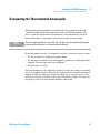
Transporting the Thermostatted Autosampler
4 Optimizing Performance
43
Controller Requirements
44
5 Maintenance
45
Introduction into Repairing the Thermostat
6 Parts and Materials for Maintenance
Main Assemblies (External Parts)
Accessory Kit G1330-68705 57
Foam Parts 58
Plastic Parts 59
7 Cable Overview
41
46
55
56
61
Cable Overview 62
Analog Cables 64
1200 Series AT User Manual
3
Contents
Remote Cables 67
BCD Cables 72
Auxiliary Cable 74
CAN/LAN Cables 75
External Contact Cable
RS-232 Cables 77
8 Appendix
76
79
General Safety Information 80
The Waste Electrical and Electronic Equipment (WEEE) Directive
(2002/96/EC) 83
Radio Interference 84
Sound Emission 85
Agilent Technologies on Internet 86
4
1200 Series AT User Manual
1200 Series AT User Manual
1
Introduction
Introduction to the Thermostatted Autosampler
Autosampler Thermostat Operation
Electrical Connections
6
8
10
Agilent Technologies
5
1
Introduction
Introduction to the Thermostatted Autosampler
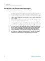
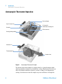
Introduction to the Thermostatted Autosampler
The Agilent 1200 Series autosampler is designed for use with other modules of
the Agilent 1200 Series LC system or with other LC systems if adequate
remote control inputs and outputs are available. The autosampler is controlled
from the Agilent 1200 Series control module or from the Agilent ChemStation
for LC systems.
The specially-designed thermostattable sample trays holds either 100 × 1.8 ml
vials or two wellplates and 10 × 1.8 ml vials.
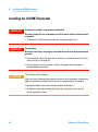
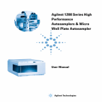
The autosampler thermostat contains Peltier-controlled heat exchangers. A
fan draws air from the area above the sample vial tray of the autosampler and
is then blown through the fins of the cooling/heating module. There it is cooled
or heated according to the temperature setting. The thermostatted air enters
the autosampler through a recess underneath the specially-designed sample
tray. The air is then distributed evenly through the sample tray ensuring
effective temperature control, regardless of how many vials are in the tray.
In cooling mode condensation is generated on the cooled side of the Peltier
elements. This condensed water is safely guided into the leak system.
6
1200 Series AT User Manual
Introduction
Introduction to the Thermostatted Autosampler
EdlZghjeean
1
I86WdVgY
=ZVih^c`[Vch
=ZVih^c`
=ZViZmX]Vc\Zg
8dcYZchVi^dcaZV`YgV^c
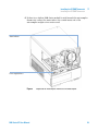
Figure 1
1200 Series AT User Manual
=ZViZmX]Vc\Zg[Vc
Overview of the Autosampler Thermostat
7
1
Introduction
Autosampler Thermostat Operation
Autosampler Thermostat Operation
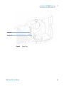
=ZViZmX]Vc\Zg
HeZX^VahVbeaZigVn
6^gX]VccZa^c
VjidhVbeaZghVbea^c\jc^i
6^gdjiaZi
EZai^ZgZaZbZcih
=ZVi^c\$Xdda^c\bdYjaZ
6bW^ZciV^g^c
I]ZgbdhiViiZYV^g
=ZViZYV^gdji
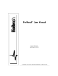
Figure 2
Autosampler Thermostat Principle
The thermostatted autosampler is equipped with a cooling/heating module
which uses Peltier elements for efficient air cooling. When turned on the front
side of the Peltier elements is heated/cooled according to the temperature
setting. A fan draws air from the sample tray area and blows it through the
8
1200 Series AT User Manual
Introduction
Autosampler Thermostat Operation
1
channels of the heating/cooling module. The fan speed is determined
according to the environmental conditions (e.g., ambient temperature,
humidity). In the heating/cooling module the air reaches the temperature of
the Peltier elements and this thermostatted air is blown underneath the
special sample tray where it is evenly distributed and streams back into the
sample tray area. From there it is again drawn into the autosampler
thermostat. This “recycle” mode assures a very efficient cooling/heating of the
sample vials.
In cooling mode the opposite side of the Peltier element will become very hot
and to maintain the performance of the elements they have to be cooled down.
This is done with large heat exchangers in the back of the autosampler
thermostat. Four fans blow air from left to right through the instrument to
remove the heated air. The fan speed is controlled according to the
temperature of the Peltier elements.
During cooling condensation will appear in the heating/cooling module. The
condensed water will be guided out of the autosampler thermostat.
1200 Series AT User Manual
9
1
Introduction
Electrical Connections
Electrical Connections
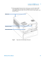
GZaVnXdciVXih
86CXVWaZidcZmibdYjaZ
K^VacjbWZgdjieji
I]Zgb"6jidhVbeaZgXVWaZ
GZbdiZ
GH'('8
86CXVWaZidegZk^djhbdYjaZ
86C"Wjh
<E>7
I]ZgbdhiVi"
6jidhVbeaZgXVWaZ
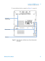
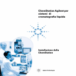
Figure 3
Electrical Connections
• The GPIB connector is used to connect the autosampler with a computer.
The address and control switch module next to the GPIB connector
determines the GPIB address of your autosampler. The switches are preset
to a default address (see Autosampler Reference Manual) and this is
recognized immediately after power on.
10
1200 Series AT User Manual
1
Introduction
Electrical Connections
• The CAN bus is a serial bus with high-speed data transfer. The two
connectors for the CAN bus are used for internal Agilent 1200 Series
module data transfer and synchronization.
• The REMOTE connector may be used in combination with other analytical
instruments from Agilent Technologies if you want to use features such as
common shut down, prepare, and so on.
• The RS-232 connector may be used to control the autosampler from a
computer through an RS-232 connection, using appropriate software. This
connector needs to be activated by the configuration switch module next to
the GPIB connector. The software needs the appropriate drivers to support
this communication. See your software documentation for further
information.
• The Thermostat-Autosampler connection is used for control signal transfer
and synchronization of the two modules. The cable must be installed for
operation of the autosampler thermostat.
• The power input socket accepts a line voltage of 100–120 or
220–240 volts AC ± 10 % with a line frequency of 50 or 60 Hz. Maximum
power consumption of the autosampler module is 300 Watts (Volt-Amps).
Maximum power consumption of the autosampler thermostat module is
260 Watts (Volt-Amps). There are no voltage selectors on your autosampler
because the power supplies have automatic selection capability. The
autosampler module has no externally accessible fuses, because automatic
electronic fuses are implemented in the power supply. The power supply of
the autosampler thermostat has two externally accessible fuses. The
security lever at the power input socket prevents removal of the
autosampler cover when line power is still connected.
• The interface board slot is used for external contacts, BCD output and for
future use.
1200 Series AT User Manual
11
1
12
Introduction
Electrical Connections
1200 Series AT User Manual
1200 Series AT User Manual
2
Site Requirements and Specifications
Site Requirements 14
Power Consideration
Power Cords 15
Bench Space 16
Environment 16
Physical Specifications
14
17
Performance Specifications
18
Agilent Technologies
13
2
Site Requirements and Specifications
Site Requirements
Site Requirements
A suitable site environment is important to ensure optimum performance of
the autosamplers.
Power Consideration
The autosamplers comprises two modules, the autosampler module (G1329A,
G1389A, G1367A, or G2260A) and the thermostat module (G1330B Therm).
Both modules have a separate power supply and a power plug for the line
connections. The two modules are connected by a control cable and both are
turned on by the autosampler module.
The autosampler power supplies have automatic voltage selectors (see Table 1
on page 17). Consequently there are no voltage selectors in the rear of the two
autosampler modules. The autosampler module has no externally accessible
fuses, because automatic electronic fuses are implemented in its power
supply. The autosampler thermostat power supply has two externally
accessible fuses.
WA R N I N G
Incorrect line voltage at the instrument
Shock hazard or damage of your instrumentation can result, if the devices are
connected to a line voltage higher than specified.
➔ Connect your instrument to the specified line voltage.
CAUTION
Unaccessable power plug.
In case of emergency it must be possible to disconnect the instrument from the power
line at any time.
➔ Make sure the power connector of the instrument can be easily reached and
unplugged.
➔ Provide sufficient space behind the power socket of the instrument to unplug the
cable.
14
1200 Series AT User Manual
2
Site Requirements and Specifications
Site Requirements
Power Cords
Different power cords are offered as options with the module. The female end
of all power cords is identical. It plugs into the power-input socket at the rear
of the module. The male end of each power cord is different and designed to
match the wall socket of a particular country or region.
WA R N I N G
The absence of ground connection and the use of an unspecified power cord can
lead to electric shock or short circuit.
Electric Shock
➔ Never operate your instrumentation from a power outlet that has no ground
connection.
➔ Never use a power cord other than the Agilent Technologies power cord designed
for your region.
WA R N I N G
Use of unsupplied cables
Using cables not supplied by Agilent Technologies can lead to damage of the
electronic components or personal injury.
➔ Never use cables other than the ones supplied by Agilent Technologies to ensure
proper functionality and compliance with safety or EMC regulations.
1200 Series AT User Manual
15
2
Site Requirements and Specifications
Site Requirements
Bench Space
The autosampler dimensions and weight (see Table 1 on page 17) allow the
instrument to be placed on almost any laboratory bench. The instrument
requires an additional 25 cm (10 inches) of space on either side for the
circulation of air, and approximately 8 cm (3.1 inches) at the rear for electrical
connections. Ensure the autosampler is installed in a level position.
If a complete Agilent 1200 Series system is to be installed on the bench, make
sure that the bench is designed to carry the weight of all the modules. For a
complete system including the thermostatted autosampler it is recommended
to position the modules in two stacks, see “Optimizing the Stack
Configuration” on page 22. Make sure that in this configuration there is 25 cm
(10 inches) space on either side of the thermostatted autosampler for the
circulation of air.
Environment
Your autosampler modules will work at ambient temperatures and relative
humidity as described in Table 1 on page 17.
CAUTION
Condensation within the module
Condensation will damage the system electronics.
➔ Do not store, ship or use your module under conditions where temperature
fluctuations could cause condensation within the module.
➔ If your module was shipped in cold weather, leave it in its box and allow it to warm
slowly to room temperature to avoid condensation.
16
1200 Series AT User Manual
2
Site Requirements and Specifications
Physical Specifications
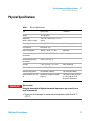
Physical Specifications
Table 1
WA R N I N G
Physical Specifications
Type
Specification
Comments
Weight
20.7 kg (46 lbs)
Dimensions
(width × depth × height)
140 × 345 × 435 mm (5.5 × 13.5 × 17
inches)
Line voltage
100 – 240 VAC, ± 10%
Line frequency
50 or 60 Hz, ± 5%
Power consumption
260 VA / 210 W / 717 BTU
Maximum
Ambient operating
temperature
4 – 55 °C (41 – 131 °F)
See warning below
Ambient non-operating
temperature
-40–70 °C (-4–158 °F)
Humidity
< 95%, at 25–40 °C (77–104 °F)
Operating Altitude
Up to 2000 m (6500 ft)
Non-operating altitude
Up to 4600 m (14950 ft)
For storing the module
Safety standards: IEC, CSA,
UL
Installation Category II, Pollution
Degree 2
For indoor use only. Research
Use Only. Not for use in
Diagnostic Procedures.
Wide-ranging capability
Non-condensing
Hot rear panel
Using the autosampler at high environmental temperatures may cause the rear
panel to become hot.
➔ Do not use the autosampler at environmental temperatures higher than 50 °C
(122 °F)
1200 Series AT User Manual
17
2
Site Requirements and Specifications
Performance Specifications
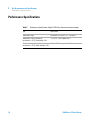
Performance Specifications
Table 2
Performance Specifications Agilent 1200 Series thermostatted autosampler
Type
Specification
Temperature range:
setable from 4 °C to 40 °C in 1 ° increments
Temperature accuracy at ambient
temperatures < 25 °C and humidity < 50%
- 1°C to + 4 °C at a setpoint of 4 °C
Temperature accuracy at ambient
- 1°C to + 5 °C at a setpoint of 4 °C
temperatures > 25 °C and/or humidity > 50%
18
1200 Series AT User Manual
1200 Series AT User Manual
3
Installing the G1330B Thermostat
Unpacking the Autosampler 20
Damaged Packaging 20
Delivery Checklist 20
Optimizing the Stack Configuration
22
Installing the G1330B Thermostat 24
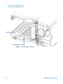
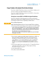
Stage 1: Preparing the Autosampler Thermostat and Autosampler
Stage 2: Power Cable and Interface Cable Connection 30
Stage 3: Flow Connections 33
Stage 4: Installing the Sample Tray 34
Stage 5: Installing Tray Cover and Front Cover 37
Stage 6: Turning on the Thermostatted Autosampler 38
Stage 7: Update of Control Module Firmware 38
Stage 8: Update of the Agilent ChemStation Software 39
Transporting the Thermostatted Autosampler
26
41
Agilent Technologies
19
3
Installing the G1330B Thermostat
Unpacking the Autosampler
Unpacking the Autosampler
CAUTION
Mechanical damage of the autosampler
If the transport assembly is not parked, the autosampler could be damaged due to
excessive shock of the shipping container during transport.
➔ Always park the transport assembly before shipment (see “Transporting the
Autosampler” in the corresponding manual).
Damaged Packaging
The two modules of the autosampler are shipped in separate boxes. Upon
receipt of your autosampler, inspect the shipping containers for any signs of
damage. If the containers or cushioning material are damaged, save them until
the contents have been checked for completeness and the autosampler has
been mechanically and electrically checked. If the shipping container or
cushioning material is damaged, notify the carrier and save the shipping
material for the carriers inspection.
Delivery Checklist
Unpack the two boxes of the autosampler. Ensure all parts and materials have
been delivered with the autosampler and the autosampler thermostat. The
delivery checklist are shown in Table 3 on page 21. Please report missing or
damaged parts to your local Agilent Technologies sales and service office.
If the thermostatted autosampler was ordered as an upgrade (G1395A) to an
existing autosampler, the shipment will also contain the required software
upgrades for your Agilent ChemStation.
20
1200 Series AT User Manual
Installing the G1330B Thermostat
Unpacking the Autosampler
Table 3
G1330B Thermostat Checklist
Description
Quantity
Autosampler Thermostat G1330B
1
Power cable
1
as ordered
Accessory kit (Table 4 on page 21)
1
G1330-68705
Table 4
Part Number
Autosampler Thermostat Accessory Kit Contents G1330-68705
Description
Part Number
Waste Tube
5063-6527
Waste Tube Assembly
G1330-67300
1200 Series AT User Manual
3
21
3
Installing the G1330B Thermostat
Optimizing the Stack Configuration
Optimizing the Stack Configuration
If your autosampler is part of a system, you can ensure optimum performance
by installing the autosampler in the stack in the position shown in Figure 4 on
page 22 and Figure 5 on page 23. This configuration optimizes the system flow
path, ensuring minimum delay volume.
>chiVcie^adi
9ZiZXidg
8dajbc
XdbeVgibZci
HdakZci
XVW^cZi
6jidhVbeaZg
9Z\VhhZg
Ejbe
I]ZgbdhiVi
Figure 4
22
Recommended Stack Configuration (Front View)
1200 Series AT User Manual
Installing the G1330B Thermostat
Optimizing the Stack Configuration
3
6cVad\h^\cVaidgZXdgYZg
<E>7idA88]ZbHiVi^dc
86CWjhXVWaZ
6jidhVbeaZg"
I]ZgbdhiVi
XVWaZ
GZbdiZXVWaZ
6cVad\h^\cVaidgZXdgYZg
Figure 5
1200 Series AT User Manual
68edlZg
68edlZg
Recommended Stack Configuration (Rear View)
23
3
Installing the G1330B Thermostat
Installing the G1330B Thermostat
Installing the G1330B Thermostat
WA R N I N G
Instrument is partially energized when switched off
The power supply still uses some power, even if the power switch on the front panel
is turned off.
➔ To disconnect the ALS thermostat from line, unplug the power cord.
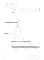
WA R N I N G
Personal injury
To avoid personal injury, keep fingers away from the needle area during autosampler
operation.
➔ Do not bend the safety flap away from its position, or attempt to remove the safety
cover (see Figure 6 on page 25).
➔ Do not attempt to insert or remove a vial from the gripper when the gripper is
positioned below the needle.
CAUTION
"Defective on arrival" problems
If there are signs of damage, please do not attempt to install the module. Inspection by
Agilent is required to evaluate if the instrument is in good condition or damaged.
➔ Notify your Agilent sales and service office about the damage.
➔ An Agilent service representative will inspect the instrument at your site and
initiate appropriate actions.
24
1200 Series AT User Manual
Installing the G1330B Thermostat
Installing the G1330B Thermostat
3
HV[Zin[aVe
HV[ZinXdkZg
Figure 6
1200 Series AT User Manual
Safety Flap.
25
3
Installing the G1330B Thermostat
Installing the G1330B Thermostat
Stage 1: Preparing the Autosampler Thermostat and Autosampler
WA R N I N G
Damage through condensation
If the condensation tube is located in liquid the condensed water cannot flow out of
the tube and the outlet is blocked. Any further condensation will then remain in the
instrument. This may damage the instruments electronics.
➔ Make sure that the condensation tube is always above the liquid level in the vessel.
NOTE
Even under average humidity conditions, a significant amount of condensed water gathers
every day. A suitable container must be provided and emptied regularly in order to avoid
overflow.
1 Place the autosampler thermostat on the bench or in the stack.
2 Remove the front cover. Press the two snap fasteners on the sides of the
cover and move it away.
26
1200 Series AT User Manual
Installing the G1330B Thermostat
Installing the G1330B Thermostat
3
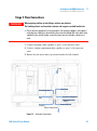
3 If the autosampler thermostat is located on top of another Agilent 1200
Series Module place the waste tube assembly into the top cover of the
autosampler thermostat and locate the other end in the waste funnel of the
module beneath.
BdYjaZadX`h
LVhiZijWZVhhZbWan
8dcYZchVi^dcaZV`ijWZ
Figure 7
1200 Series AT User Manual
Preparation of the Autosampler Thermostat
27
3
Installing the G1330B Thermostat
Installing the G1330B Thermostat
4 Connect the condensation leak tube to the main waste exit of the
autosampler thermostat and place into an appropriate vessel. It is possible
to either let the condensation leak tubing exit the module at the front or at
the left side of the module. Make sure that the leak tube is fully fixed on the
outlet.
8dcYZchVi^dcaZV`ijWZ
LVhiZWdiiaZ
Figure 8
Condensation Leak outlet
5 Install the front cover of the autosampler thermostat.
6 Place the autosampler module on top of the autosampler thermostat. Make
sure that the autosampler is correctly engaged in the autosampler
thermostat locks.
7 Place the air channel adapter into the autosampler tray base. Make sure the
adapter is fully pressed down. This assures that the cold airstream from the
autosampler thermostat is correctly guided to the tray area of the
autosampler.
28
1200 Series AT User Manual
3
Installing the G1330B Thermostat
Installing the G1330B Thermostat
8 If there is no Agilent 1200 Series module located beneath the autosampler
thermostat connect the waste tube to the central waste exit of the
autosampler and place in a waste vessel.
HiVijh^cY^XVidg
EdlZghjeean^cY^XVidg
Figure 9
1200 Series AT User Manual
Preparation of Autosampler Thermostat and Autosampler
29
3
Installing the G1330B Thermostat
Installing the G1330B Thermostat
Stage 2: Power Cable and Interface Cable Connection
WA R N I N G
Damaged electronics
Disconnecting or reconnecting the autosampler to autosampler thermostat cable
when the power cords are connected to either of the two modules will damage the
electronics of the modules. In such a case, mainboards of both instruments must be
exchanged, otherwise they can damage the other instrument.
➔ Make sure the power cords are unplugged before disconnecting or reconnecting the
autosampler to autosampler thermostat cable.
1 Ensure the power switch on the front of the autosampler is OFF and the
power cables are disconnected.
2 Connect the cable between the autosampler and the autosampler
thermostat, see Figure 10 on page 31.
3 Move the safety lever at the rear of the two modules to the right position,
see Figure 10 on page 31.
4 Connect the power cables to the power connectors.
5 Connect the CAN interface cables to other modules in the system (see
Figure 5 on page 23 and Figure 11 on page 32).
6 If required, connect additional interface and control cables to the
autosampler (see Figure 5 on page 23 and Figure 11 on page 32). Refer to
the documentation of the Agilent 1200 Series control module or
ChemStation for LC for more information.
NOTE
30
In an Agilent 1200 Series system, the individual modules are connected by a CAN cable.
The Agilent 1200 Series control module can be connected to the CAN bus at any of the
modules in the system. The Agilent Chemstation can be connected to the system by one
GPIB cable at any of the modules, however, it is recommended to connect the GPIB cable to
the detector. For more information about connecting the control module or ChemStation
refer to the respective user manual. For connecting the Agilent 1200 Series equipment to
non-Agilent 1200 Series equipment, see Autosampler manual).
1200 Series AT User Manual
Installing the G1330B Thermostat
Installing the G1330B Thermostat
3
7 Connect additional cables as required (see Figure 11 on page 32).
6jidhVbeaZg"
I]ZgbdhiVi8VWaZ
EdlZgXdccZXidg
HV[ZinaZkZg
Figure 10
1200 Series AT User Manual
Power Connectors and Safety Levers at Rear of thermostatted
Autosampler.
31
3
Installing the G1330B Thermostat
Installing the G1330B Thermostat
GZaVnXdciVXih
86CXVWaZidcZmibdYjaZ
K^VacjbWZgdjieji
I]Zgb"6jidhVbeaZgXVWaZ
GZbdiZ
GH'('8
86C"Wjh
<E>7
86CXVWaZidegZk^djhbdYjaZ
I]ZgbdhiVi"
6jidhVbeaZgXVWaZ
Figure 11
32
Cable Connections.
1200 Series AT User Manual
3
Installing the G1330B Thermostat
Installing the G1330B Thermostat
Stage 3: Flow Connections
WA R N I N G
When opening capillary or tube fittings solvents may leak out.
The handling of toxic and hazardous solvents and reagents can hold health risks.
➔ Please observe appropriate safety procedures (for example, goggles, safety gloves
and protective clothing) as described in the material handling and safety data sheet
supplied by the solvent vendor, especially when toxic or hazardous solvents are
used.
1 Connect the pump outlet capillary to port 1 of the injection valve.
2 Connect column-compartment inlet capillary to port 6 of the injection
valve.
3 Ensure that the waste tube is positioned inside the leak channel.
Ejbe
IdbZiZg^c\YZk^XZ
;gdbejbe
IdXdajbcXdbeVgibZci
Eaj\
LVhiZijWZ^caZV`
X]VccZa
IdlVhiZ
;gdbcZZYaZhZVi
8dajbcXdbeVgibZci
Figure 12
1200 Series AT User Manual
Hydraulic Connections
33
3
Installing the G1330B Thermostat
Installing the G1330B Thermostat
Stage 4: Installing the Sample Tray
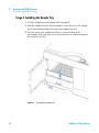
1 Load the sample tray with sample vials as required.
2 Slide the sample tray into the autosampler so that the rear of the sample
tray is seated firmly against the rear of the sample-tray area.
3 Press the front of the sample tray down to secure the tray in the
autosampler. If the tray pops out of its position the air channel adapter is
not inserted correctly.
Figure 13
34
Installing the Sample Tray
1200 Series AT User Manual
3
Installing the G1330B Thermostat
Installing the G1330B Thermostat
Half-Tray Combinations
NOTE
In the autosampler only the 100 vial tray is supported for temperature control of the vials.
Nevertheless the half trays of the standard autosampler (G1313A) can be used in the
thermostatted autosampler as well. However when these trays are installed cooling or
heating of the vials in the tray will not work.
Half-trays can be installed in any combination enabling both 1.8 ml-and
6 ml-vials to be used simultaneously.
Numbering of Vial Positions
The standard 100-vial tray has vial positions 1 to 100. However, when using
two half-trays, the numbering convention is slightly different. The vial
positions of the right-hand half tray begin at position 101 as follows:
Left-hand 40-position tray: 1–40
Left-hand 15-position tray: 1–15
Right-hand 40-position tray: 101–140
Right-hand 15-position tray: 101–115
1200 Series AT User Manual
35
3
Installing the G1330B Thermostat
Installing the G1330B Thermostat
Edh^i^dc&
Edh^i^dc&%&
Figure 14
36
Numbering of Tray Positions.
1200 Series AT User Manual
Installing the G1330B Thermostat
Installing the G1330B Thermostat
3
Stage 5: Installing Tray Cover and Front Cover
1 Fix the tray cover in the clips of the left autosampler cover side by sliding it
in position. Do not close the tray cover.
2 Position the front cover in the top left corner of the autosampler and turn it
towards the instrument. Press the stop fastener to secure it in the right side
cover of the autosampler.
3 Close the tray cover.
IgVnXdkZg
6jidhVbeaZg[gdciYddg
Figure 15
1200 Series AT User Manual
Installation of Tray Cover and Front Cover of the Autosampler
37
3
Installing the G1330B Thermostat
Installing the G1330B Thermostat
Stage 6: Turning on the Thermostatted Autosampler
1 Depress the power switch to turn on the two modules of the autosampler.
NOTE
The power switch stays depressed (1) and a green indicator lamp in the power switch is on
when the autosampler is turned on. When the line power switch stands out (Ø) and the
green light is off, the autosampler is turned off.
Stage 7: Update of Control Module Firmware
If the control module has a firmware revision A.01.30 or higher, you do not
need to update the control module firmware.
If you have a control module version A.01.30 or lower, update the firmware as
described.
1 Disconnect the control module before inserting the PC card.
2 Insert the PC card into the card slot of the control module.
3 Reconnect the control module for restarting it.
4 Press “System” (F5) - “Records” (F4). Highlight the LC-System line in the
display using the up-down arrows.
5 Press “FW-Update” (F5).
6 Select the file for the firmware update (LCB202en.BIN).
7 Press “Execute” and select “Yes” to confirm loading of the new firmware.
The control module reboots and loads the firmware indicated by (.) and (*)
on the display. When finished with the update the control module reboots
again.
8 Check that the correct firmware was loaded by pressing “System” (F5) “Records” (F4).
9 Disconnect the control module and remove the PC card by pressing the
card-eject button.
38
1200 Series AT User Manual
3
Installing the G1330B Thermostat
Installing the G1330B Thermostat
Stage 8: Update of the Agilent ChemStation Software
If you have a Agilent ChemStation software version A.05.02 or higher, you do
not need to update your Agilent ChemStation software.
If you have a Agilent ChemStation software version A.05.01 or lower, please
update your software as described.
Starting from revision A.04.01 or A.04.02 of the Agilent ChemStation
If you have ordered the G1395A Upgrade kit you will be provided with a
A.04.02 and a A.05.01 update CD ROM, which gives you the choice of keeping
your old major software version or updating to A.05.01 release.
CAUTION
Hard- and Software Requirements
Agilent ChemStation Software will not run, if you use wrong PC hard- and software.
➔ Ensure that your PC hard- and software meets the requirements for A.05.01. A.05.01
requires Windows 95 or Windows NT 4.0 as operating system and a Pentium PC
with a minimum of 24 MB (NT -systems require also GPIB board Agilent 82341C).
Publication 12-5965-6805E gives detailed information about the PC requirements.
The application note can be obtained from the Internet
(http://www.chem.agilent.com/cag/literature/apglit.html) or your local Agilent
Technologies sales office.
1 If you decide to update your A.04.01 Agilent ChemStation to A.05.01, use
the provided A.05.01 CD-ROM and follow the steps described in the
Installing your ChemStation manual, provided as portable document
format (PDF) file on the A.05.01 CD-ROM in the directory MANUALS\
INSTALL\LC. If you do not already have the Adobe Acrobat reader
installed, use the file MANUALS\READER\AR32e30.EXE to install the
reader.
2 After you have updated your system, insert the 3.5” floppy labeled ‘Driver
update Disk (A.05.02 Beta)’ and open a DOS prompt by selecting
Start->RUN and typing command.
3 At the DOS prompt type A:.
4 Press Enter and then HPUPDATE.
1200 Series AT User Manual
39
3
Installing the G1330B Thermostat
Installing the G1330B Thermostat
Press Enter only if your Agilent ChemStation is installed in the directory
C:\HPCHEM. If your Agilent ChemStation is installed in a different
directory, e.g. D:\HPCHEM, you need to type HPUPDATE D:\HPCHEM and
press Enter.
5 If you decide to update to A.04.02, insert the A.04.02 CD-ROM and select
SETUP on the CD-ROM using File Manager or Explorer. Select Yes to
continue with the update.
6 After you have updated your system, insert the 3.5 inch floppy labeled
Driver update Disk (A.04.03) and open a DOS prompt by selecting
Start->RUN and typing command. At the DOS prompt type A: and press
Enter and then HPUPDATE.
Press Enter only if your Agilent ChemStation is installed in the directory
C:\HPCHEM. If your Agilent ChemStation is installed in a different
directory, e.g. D:\HPCHEM, you need to type HPUPDATE D:\HPCHEM and
press Enter.
Starting from revision A.05.01 of the Agilent ChemStation
If you already have the Agilent ChemStation A.05.01 installed, you only need
to install the update to A.05.02 Beta. This update comprises only the driver for
the thermostatted autosampler, no other changes are made.
1 Insert the 3.5” floppy labeled Driver update Disk (A.05.02 Beta).
2 Open a DOS prompt by selecting Start->RUN and typing command.
3 At the DOS prompt type A:.
4 Press Enter and then HPUPDATE.
5 Press Enter only if your Agilent ChemStation is installed in the directory
C:\HPCHEM.
If your Agilent ChemStation is installed in a different directory, e.g. D:\
HPCHEM, you need to type HPUPDATE D:\HPCHEM and press Enter.
40
1200 Series AT User Manual
3
Installing the G1330B Thermostat
Transporting the Thermostatted Autosampler
Transporting the Thermostatted Autosampler
When moving the autosampler around the laboratory, make sure that any
condensed water inside the thermostat is removed. Tilt the module to the
front, so that the water inside the thermostat can safely flow into the leak
funnel. Otherwise no special precautions are needed for the modules.
NOTE
The autosampler thermostat is heavy (20.7 kg, 45.6 lbs). Carry the module by putting your
hands under the side covers in a central position of the unit.
If the autosampler needs to be shipped to another location via carrier, ensure:
• The two modules are shipped in separate boxes.
• The transport assembly of the autosampler is parked, see “Park Arm (Park
Gripper)” in your respective Service Manual.
• The vial tray is secured.
If the autosampler is to be shipped to another location, the transport assembly
of the autosampler must be moved to the park position to prevent mechanical
damage should the shipping container be subjected to excessive shock. Also,
ensure the vial tray is secured in place with suitable packaging, otherwise the
tray may become loose and damage internal components.
1200 Series AT User Manual
41
3
42
Installing the G1330B Thermostat
Transporting the Thermostatted Autosampler
1200 Series AT User Manual
1200 Series AT User Manual
4
Optimizing Performance
Controller Requirements
44
Agilent Technologies
43
4
Optimizing Performance
Controller Requirements
Controller Requirements
Agilent 1200 Series control module and Agilent ChemStation must have the
latest revision firmware/software loaded to allow optimum operation with the
thermostattable autosamplers. Older revisions might not recognize or have full
functionality with the thermostattable autosampler.
Control Module Firmware requirements
The control module requires firmware revision A.01.30 or higher to control
the thermostatted autosampler. Previous firmware revisions of the control
module will not run with the thermostatted autosampler. If the control module
was shipped together with the thermostatted autosampler the control module
firmware does not require updating. The firmware update must be done with
a PCMCIA card that has the newest revision loaded. The firmware is not part
of the shipment of the thermostatted autosampler. Contact your local Agilent
Technologies sales and service office for the firmware update of the control
module. For the update procedure see “Stage 7: Update of Control Module
Firmware” on page 38.
Agilent ChemStation Software requirements
To control the thermostatted autosampler from a PC, the Agilent ChemStation
software version A.04.03, or A.05.02beta, or A.05.02 or higher is required.
These software revision might however not support all autosampler modules.
The thermostatted autosampler will not run with any previous version of the
Agilent ChemStation software. The software updates are part of the
thermostatted autosampler shipment. For the update procedure see “Stage 8:
Update of the Agilent ChemStation Software” on page 39.
44
1200 Series AT User Manual
1200 Series AT User Manual
5
Maintenance
Introduction into Repairing the Thermostat 46
Simple Repairs - Maintenance 46
Exchanging Internal Parts - Repairs 46
Warnings and Cautions 47
Using the ESD Strap 48
Cleaning the Thermostat 48
Exchanging the Power Supply Fuses 49
Removing the Top Cover and Foam 51
Assembling the Main Cover 53
Agilent Technologies
45
5
Maintenance
Introduction into Repairing the Thermostat
Introduction into Repairing the Thermostat
Simple Repairs - Maintenance
The ALS thermostat is designed for easy repair.
Exchanging Internal Parts - Repairs
Some repairs may require exchange of defective internal parts. Exchange of
these parts requires removing the ALS thermostat from the stack, removing
the covers, and disassembling the ALS thermostat. The security lever at the
power input socket prevents that the Thermostat cover is taken off when line
power is still connected.
46
1200 Series AT User Manual
Maintenance
Introduction into Repairing the Thermostat
5
Warnings and Cautions
WA R N I N G
Instrument is partially energized when switched off, as long as the power cord is
plugged in.
Risk of stroke and other personal injury. Repair work at the module can lead to
personal injuries, e. g. shock hazard, when the module cover is opened and the
instrument is connected to power.
➔ Never perform any adjustment, maintenance or repair of the module with the top
cover removed and with the power cord plugged in.
➔ The security lever at the power input socket prevents that the module cover is taken
off when line power is still connected. Never plug the power line back in when cover
is removed.
WA R N I N G
Damaged electronics
Disconnecting or reconnecting the autosampler to autosampler thermostat cable
when the power cords are connected to either of the two modules will damage the
electronics of the modules. In such a case, mainboards of both instruments must be
exchanged, otherwise they can damage the other instrument.
➔ Make sure the power cords are unplugged before disconnecting or reconnecting the
autosampler to autosampler thermostat cable.
CAUTION
Electrostatic discharge at electronic boards and components
Electronic boards and components are sensitive to electrostatic discharge (ESD).
➔ In order to prevent damage always use an ESD protection (for example, an ESD
wrist strap) when handling electronic boards and components.
1200 Series AT User Manual
47
5
Maintenance
Introduction into Repairing the Thermostat
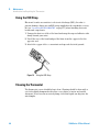
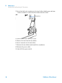
Using the ESD Strap
Electronic boards are sensitive to electronic discharge (ESD). In order to
prevent damage, always use an ESD strap supplied in the standard accessory
kit (see “Accessory Kit G1330-68705” on page 57) when handling electronic
boards and components.
1 Unwrap the first two folds of the band and wrap the exposed adhesive side
firmly around your wrist.
2 Unroll the rest of the band and peel the liner from the copper foil at the
opposite end.
3 Attach the copper foil to a convenient and exposed electrical ground.
Figure 16
Using the ESD Strap
Cleaning the Thermostat
The thermostat covers should be kept clean. Cleaning should be done with a
soft cloth slightly dampened with water or a solution of water and a mild
detergent. Do not use an excessively damp cloth that liquid can drip into the
autosampler.
48
1200 Series AT User Manual
Maintenance
Introduction into Repairing the Thermostat
5
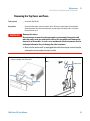
Exchanging the Power Supply Fuses
The fuse holders are located on the rear panel of the autosampler thermostat.
When
If wrong fuses are installed. Required is 2.5A fuses.
Tools required
•
Parts required
#
Description
2110-0015
Fuses T2.5 A/250V (CSA, UL listed)
WA R N I N G
Flat head screwdriver
Damaged electronics
Disconnecting or reconnecting the autosampler to autosampler thermostat cable
when the power cords are connected to either of the two modules will damage the
electronics of the modules. In such a case, mainboards of both instruments must be
exchanged, otherwise they can damage the other instrument.
➔ Make sure the power cords are unplugged before disconnecting or reconnecting the
autosampler to autosampler thermostat cable.
1 Switch OFF the power switch at the front of the thermostatted autosampler.
2 Remove the power cable from the two modules.
1200 Series AT User Manual
49
5
Maintenance
Introduction into Repairing the Thermostat
3 Insert the flat head screwdriver in the fuse holder, slightly press and turn
counter clockwise to release the fuse holder from the socket.
Eg^bVgn[jhZh
4 Pull the fuse holder out of the socket.
5 Remove the fuse from the fuse holder.
6 Insert a new fuse in the fuse holder.
7 Reinsert the fuse holder and fix with the screwdriver.
8 Reinsert the power cables.
9 Switch ON the power switch.
50
1200 Series AT User Manual
Maintenance
Introduction into Repairing the Thermostat
5
Removing the Top Cover and Foam
Tools required
•
Screwdriver Pozidriv #1
Preparations
•
Switch off autosampler at the main power switch. Disconnect autosampler and autosampler
thermostat power cords. Remove autosampler to autosampler thermostat cable, and remove
thermostat from stack.
WA R N I N G
Damaged electronics
Disconnecting or reconnecting the autosampler to autosampler thermostat cable
when the power cords are connected to either of the two modules will damage the
electronics of the modules. In such a case, mainboards of both instruments must be
exchanged, otherwise they can damage the other instrument.
➔ Make sure the power cords are unplugged before disconnecting or reconnecting the
autosampler to autosampler thermostat cable.
1 Remove the front cover by pressing the both clip
2 Move the lever towards the power socket.
fasteners on both sides of the cover.
Eg^bVgn[jhZh
1200 Series AT User Manual
51
5
Maintenance
Introduction into Repairing the Thermostat
4 Unscrew the screws on the top plate and remove the
3 Lift the clips on both sides of the top cover (1). Remove
the top cover (2).
plate by lifting its back first and then sliding to the front.
'
&
HXgZlh
&
5 Unplug all wires at the TCA Board and remove them from 6 Remove the top foam.
top foam.
52
1200 Series AT User Manual
Maintenance
Introduction into Repairing the Thermostat
5
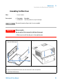
Assembling the Main Cover
When
•
Parts required
#
Part number
Description
1
G1330-68723
Cover kit (includes base, top, left and right)
NOTE
WA R N I N G
If cover is broken
The cover kit contains all parts, but it is not assembled.
Wrong assembly
You may not be able to remove the side from the top part.
➔ Make sure to install the side parts in the right direction.
1 Place the top part on the bench and insert the left and
2 Replace the cover.
right side into the top part.
;gdci
Next Steps:
3 Replace the ALS thermostat into the stack and reconnect the cables and capillaries.
4 Turn ON the ALS thermostat.
1200 Series AT User Manual
53
5
54
Maintenance
Introduction into Repairing the Thermostat
1200 Series AT User Manual
1200 Series AT User Manual
6
Parts and Materials for Maintenance
Main Assemblies (External Parts)
Accessory Kit G1330-68705
Foam Parts
Plastic Parts
56
57
58
59
Agilent Technologies
55
6
Parts and Materials for Maintenance
Main Assemblies (External Parts)
Main Assemblies (External Parts)
'
&
(
Figure 17
Table 5
56
Main Assemblies
Main Assemblies
Item
Description
Part Number
1
Fuse - Power Supply (T2.5A/250V; CSA, UL listed)
2110-0015
2
Fuse TCA - Board (T3A/250V; CSA, UL listed)
2110-0029
3
Front Cover
5065-9982
Cable, autosampler - autosampler thermostat
G1330-81600
1200 Series AT User Manual
Parts and Materials for Maintenance
Accessory Kit G1330-68705
6
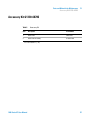
Accessory Kit G1330-68705
Table 6
Item
Accessory Kit
Description
1
1
Waste Tube
2
Waste Tube Assembly
1
Part Number
5062-2463
G1330-67300
Reorder Number (5 m)
1200 Series AT User Manual
57
6
Parts and Materials for Maintenance
Foam Parts
Foam Parts
&
'
Figure 18
Table 7
58
Foam Parts
Main Assemblies
Item
Description
Part Number
1
Top Foam
G1330-40102
2
Bottom Foam
G1330-40103
1200 Series AT User Manual
Parts and Materials for Maintenance
Plastic Parts
6
Plastic Parts
&
'
Figure 19
1200 Series AT User Manual
Plastic Parts (1)
59
6
Parts and Materials for Maintenance
Plastic Parts
(
Figure 20
Table 8
60
Plastic Parts (2)
Main Assemblies
Item
Description
Part Number
1
Cabinet Kit, includes base, top and sides
G1330-68723
2
Front Cover
5065-9982
3
Leak Pan
5042-8567
1200 Series AT User Manual
1200 Series AT User Manual
7
Cable Overview
Cable Overview
62
Analog Cables
64
Remote Cables
67
BCD Cables
72
Auxiliary Cable
74
CAN/LAN Cables
75
External Contact Cable
RS-232 Cables
76
77
Agilent Technologies
61
7
Cable Overview
Cable Overview
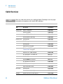
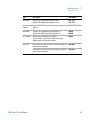
Cable Overview
NOTE
Never use cables other than the ones supplied by Agilent Technologies to ensure proper
functionality and compliance with safety or EMC regulations.
Type
Description
Part Number
Analog cables
3390/2/3 integrators
01040-60101
3394/6 integrators
35900-60750
Agilent 35900A A/D converter
35900-60750
General purpose (spade lugs)
01046-60105
3390 integrator
01046-60203
3392/3 integrators
01046-60206
3394 integrator
01046-60210
3396A (Series I) integrator
03394-60600
Remote cables
3396 Series II / 3395A integrator, see details in section
“Remote Cables” on page 67
BCD cables
Auxiliary
62
3396 Series III / 3395B integrator
03396-61010
HP 1050 modules / HP 1046A FLD
5061-3378
HP 1046A FLD
5061-3378
Agilent 35900A A/D converter
5061-3378
HP 1040 diode-array detector
01046-60202
HP 1090 liquid chromatographs
01046-60202
Signal distribution module
01046-60202
3396 integrator
03396-60560
General purpose (spade Lugs)
G1351-81600
Agilent 1100 Series vacuum degasser
G1322-61600
1200 Series AT User Manual
Cable Overview
Cable Overview
Type
Description
Part Number
CAN cables
Agilent 1100/1200 module to module,0.5m lg
Agilent 1100/1200 module to module, 1m lg
5181-1516
5181-1519
External
contacts
Agilent 1100/1200 Series interface board to general
purpose
G1103-61611
GPIB cable
Agilent 1100/1200 module to ChemStation, 1 m
Agilent 1100/1200 module to ChemStation, 2 m
10833A
10833B
RS-232 cable
Agilent 1100/1200 module to a computer
This kit contains a 9-pin female to 9-pin female Null
Modem (printer) cable and one adapter.
34398A
LAN cable
Twisted pair cross over LAN cable, (shielded 3m long) (for
point to point connection)
5023-0203
Twisted pair cross over LAN cable, (shielded 7m long) (for
point to point connection)
5023-0202
1200 Series AT User Manual
7
63
7
Cable Overview
Analog Cables
Analog Cables
One end of these cables provides a BNC connector to be connected to
Agilent 1100/1200 Series modules. The other end depends on the instrument
to which connection is being made.
Agilent 1100/1200 to 3390/2/3 Integrators
Connector01040-60101
Pin 3390/2/3
Pin Agilent
1100/1200
Signal Name
1
Shield
Ground
2
3
Not connected
Center
4
5
64
Signal +
Connected to pin 6
Shield
Analog -
6
Connected to pin 4
7
Key
8
Not connected
1200 Series AT User Manual
Cable Overview
Analog Cables
7
Agilent 1100/1200 to 3394/6 Integrators
Connector35900-60750
Pin 3394/6
Pin Agilent
1100/1200
1
Signal Name
Not connected
2
Shield
Analog -
3
Center
Analog +
Pin BNC
Pin Agilent
1100/1200
Signal Name
Shield
Shield
Analog -
Center
Center
Analog +
Agilent 1100/1200 to BNC Connector
Connector8120-1840
1200 Series AT User Manual
65
7
Cable Overview
Analog Cables
Agilent 1100/1200 to General Purpose
Connector01046-60105
Pin 3394/6
Pin Agilent
1100/1200
1
66
Signal Name
Not connected
2
Black
Analog -
3
Red
Analog +
1200 Series AT User Manual
Cable Overview
Remote Cables
7
Remote Cables
One end of these cables provides a Agilent Technologies APG (Analytical
Products Group) remote connector to be connected to Agilent 1100/1200
Series modules. The other end depends on the instrument to be connected to.
Agilent 1100/1200 to 3390 Integrators
Connector01046-60203
1200 Series AT User Manual
Pin 3390
Pin Agilent
1100/1200
Signal Name
Active
(TTL)
2
1 - White
Digital ground
NC
2 - Brown
Prepare run
Low
7
3 - Gray
Start
Low
NC
4 - Blue
Shut down
Low
NC
5 - Pink
Not connected
NC
6 - Yellow
Power on
High
NC
7 - Red
Ready
High
NC
8 - Green
Stop
Low
NC
9 - Black
Start request
Low
67
7
Cable Overview
Remote Cables
Agilent 1100/1200 to 3392/3 Integrators
Connector01046-60206
Pin 3392/3
Pin Agilent
1100/1200
Signal Name
Active
(TTL)
3
1 - White
Digital ground
NC
2 - Brown
Prepare run
Low
11
3 - Gray
Start
Low
NC
4 - Blue
Shut down
Low
NC
5 - Pink
Not connected
NC
6 - Yellow
Power on
High
9
7 - Red
Ready
High
1
8 - Green
Stop
Low
NC
9 - Black
Start request
Low
Pin 3394
Pin Agilent
1100/1200
Signal Name
Active
(TTL)
9
1 - White
Digital ground
NC
2 - Brown
Prepare run
Low
3
3 - Gray
Start
Low
NC
4 - Blue
Shut down
Low
NC
5 - Pink
Not connected
NC
6 - Yellow
Power on
High
5,14
7 - Red
Ready
High
6
8 - Green
Stop
Low
1
9 - Black
Start request
Low
Agilent 1100/1200 to 3394 Integrators
Connector01046-60210
13, 15
68
Not connected
1200 Series AT User Manual
Cable Overview
Remote Cables
NOTE
7
START and STOP are connected via diodes to pin 3 of the 3394 connector.
Agilent 1100/1200 to 3396A Integrators
Connector03394-60600
Pin 3394
Pin Agilent
1100/1200
Signal Name
9
1 - White
Digital ground
NC
2 - Brown
Prepare run
Low
3
3 - Gray
Start
Low
NC
4 - Blue
Shut down
Low
NC
5 - Pink
Not connected
NC
6 - Yellow
Power on
High
5,14
7 - Red
Ready
High
1
8 - Green
Stop
Low
NC
9 - Black
Start request
Low
13, 15
Active
(TTL)
Not connected
Agilent 1100/1200 to 3396 Series II / 3395A Integrators
Use the cable part number: 03394-60600 and cut pin #5 on the integrator side.
Otherwise the integrator prints START; not ready.
1200 Series AT User Manual
69
7
Cable Overview
Remote Cables
Agilent 1100/1200 to 3396 Series III / 3395B Integrators
Connector03396-61010
Pin 33XX
Pin Agilent
1100/1200
Signal Name
9
1 - White
Digital ground
NC
2 - Brown
Prepare run
Low
3
3 - Gray
Start
Low
NC
4 - Blue
Shut down
Low
NC
5 - Pink
Not connected
NC
6 - Yellow
Power on
High
14
7 - Red
Ready
High
4
8 - Green
Stop
Low
NC
9 - Black
Start request
Low
13, 15
Active
(TTL)
Not connected
Agilent 1100/1200 to HP 1050, HP 1046A or Agilent 35900 A/D Converters
Connector5061-3378
70
Pin HP
1050/....
Pin Agilent
1100/1200
Signal Name
Active
(TTL)
1 - White
1 - White
Digital ground
2 - Brown
2 - Brown
Prepare run
Low
3 - Gray
3 - Gray
Start
Low
4 - Blue
4 - Blue
Shut down
Low
5 - Pink
5 - Pink
Not connected
6 - Yellow
6 - Yellow
Power on
High
7 - Red
7 - Red
Ready
High
8 - Green
8 - Green
Stop
Low
9 - Black
9 - Black
Start request
Low
1200 Series AT User Manual
Cable Overview
Remote Cables
7
Agilent 1100/1200 to HP 1090 LC or Signal Distribution Module
Connector01046-60202
Pin HP 1090
Pin Agilent
1100/1200
Signal Name
Active
(TTL)
1
1 - White
Digital ground
NC
2 - Brown
Prepare run
Low
4
3 - Gray
Start
Low
7
4 - Blue
Shut down
Low
8
5 - Pink
Not connected
NC
6 - Yellow
Power on
High
3
7 - Red
Ready
High
6
8 - Green
Stop
Low
NC
9 - Black
Start request
Low
Pin Agilent
1100/1200
Signal Name
Active
(TTL)
1 - White
Digital ground
2 - Brown
Prepare run
Low
3 - Gray
Start
Low
4 - Blue
Shut down
Low
5 - Pink
Not connected
6 - Yellow
Power on
High
7 - Red
Ready
High
8 - Green
Stop
Low
9 - Black
Start request
Low
Agilent 1100/1200 to General Purpose
Connector01046-60201
1200 Series AT User Manual
Pin Universal
71
7
Cable Overview
BCD Cables
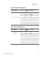
BCD Cables
One end of these cables provides a 15-pin BCD connector to be connected to
the Agilent 1200 Series modules. The other end depends on the instrument to
be connected to
Agilent 1200 to General Purpose
ConnectorG1351-81600
72
Wire Color
Pin Agilent
1200
Signal Name
BCD Digit
Green
1
BCD 5
20
Violet
2
BCD 7
80
Blue
3
BCD 6
40
Yellow
4
BCD 4
10
Black
5
BCD 0
1
Orange
6
BCD 3
8
Red
7
BCD 2
4
Brown
8
BCD 1
2
Gray
9
Digital ground
Gray
Gray/pink
10
BCD 11
800
Red/blue
11
BCD 10
400
White/green
12
BCD 9
200
Brown/green
13
BCD 8
100
not connected
14
not connected
15
+5V
Low
1200 Series AT User Manual
Cable Overview
BCD Cables
7
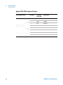
Agilent 1200 to 3396 Integrators
Connector03396-60560
1200 Series AT User Manual
Pin 3392/3
Pin Agilent
1200
Signal Name
BCD Digit
1
1
BCD 5
20
2
2
BCD 7
80
3
3
BCD 6
40
4
4
BCD 4
10
5
5
BCD0
1
6
6
BCD 3
8
7
7
BCD 2
4
8
8
BCD 1
2
9
9
Digital ground
NC
15
+5V
Low
73
7
Cable Overview
Auxiliary Cable
Auxiliary Cable
One end of this cable provides a modular plug to be connected to the
Agilent 1100 Series vacuum degasser. The other end is for general purpose.
Agilent 1100 Series Degasser to general purposes
ConnectorG1322-81600
74
Color
Pin Agilent
1100
Signal Name
White
1
Ground
Brown
2
Pressure signal
Green
3
Yellow
4
Grey
5
DC + 5 V IN
Pink
6
Vent
1200 Series AT User Manual
Cable Overview
CAN/LAN Cables
7
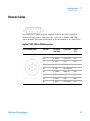
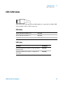
CAN/LAN Cables
Both ends of this cable provide a modular plug to be connected to Agilent 1200
Series module’s CAN or LAN connectors.
CAN Cables
Agilent 1200 module to module, 0.5 m
5181-1516
Agilent 1200 module to module, 1 m
5181-1519
Agilent 1200 module to control module
G1323-81600
LAN Cables
Description
Part number
Cross-over network cable (shielded, 3 m long), (for point to
point connection)
5023-0203
Twisted pair network cable (shielded, 7 m long) (for hub
connections)
5023-0202
1200 Series AT User Manual
75
7
Cable Overview
External Contact Cable
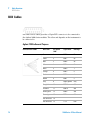
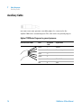
External Contact Cable
5
10
15
1
6
11
One end of this cable provides a 15-pin plug to be connected to Agilent 1200
Series module’s interface board. The other end is for general purpose.
Agilent 1200 Series Interface Board to general purposes
ConnectorG1103-61611
76
Color
Pin Agilent
1200
Signal Name
White
1
EXT 1
Brown
2
EXT 1
Green
3
EXT 2
Yellow
4
EXT 2
Grey
5
EXT 3
Pink
6
EXT 3
Blue
7
EXT 4
Red
8
EXT 4
Black
9
Not connected
Violet
10
Not connected
Grey/pink
11
Not connected
Red/blue
12
Not connected
White/green
13
Not connected
Brown/green
14
Not connected
White/yellow
15
Not connected
1200 Series AT User Manual
Cable Overview
RS-232 Cables
7
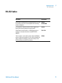
RS-232 Cables
Description
Part number
RS-232 cable, instrument to PC, 9-to-9 pin (female) This cable
has special pin-out, and is not compatible with connecting
printers and plotters.
24542U
G1530-60600
RS-232 cable kit, 9-to-9 pin (female) and one adapter 9-pin
(male) 25-pin female. Suited for instrument to PC.
34398A
Cable Printer Serial & Parallel, is a SUB-D 9 pin female vs.
Centronics connector on the other end (NOT FOR FW
UPDATE).
5181-1529
This kit contains a 9-pin female to 9-pin female Null Modem
(printer) cable and one adapter. Use the cable and adapter to
connect Agilent Technologies instruments with 9-pin male
RS-232 connectors to most PCs or printers.
34398A
1200 Series AT User Manual
77
7
78
Cable Overview
RS-232 Cables
1200 Series AT User Manual
1200 Series AT User Manual
8
Appendix
General Safety Information
80
The Waste Electrical and Electronic Equipment (WEEE) Directive
(2002/96/EC) 83
Radio Interference
Sound Emission
84
85
Agilent Technologies on Internet
86
Agilent Technologies
79
8
Appendix
General Safety Information
General Safety Information
General Safety Information
The following general safety precautions must be observed during all phases of
operation, service, and repair of this instrument. Failure to comply with these
precautions or with specific warnings elsewhere in this manual violates safety
standards of design, manufacture, and intended use of the instrument. Agilent
Technologies assumes no liability for the customer’s failure to comply with
these requirements.
General
This is a Safety Class I instrument (provided with terminal for protective
earthing) and has been manufactured and tested according to international
safety standards.
Operation
Before applying power, comply with the installation section. Additionally the
following must be observed.
Do not remove instrument covers when operating. Before the instrument is
switched on, all protective earth terminals, extension cords,
auto-transformers, and devices connected to it must be connected to a
protective earth via a ground socket. Any interruption of the protective earth
grounding will cause a potential shock hazard that could result in serious
personal injury. Whenever it is likely that the protection has been impaired,
the instrument must be made inoperative and be secured against any intended
operation.
Make sure that only fuses with the required rated current and of the specified
type (normal blow, time delay, and so on) are used for replacement. The use of
repaired fuses and the short-circuiting of fuse holders must be avoided.
80
1200 Series AT User Manual
8
Appendix
General Safety Information
CAUTION
Ensure the proper usage of the equipment.
The protection provided by the equipment may be impaired.
➔ The operator of this instrument is advised to use the equipment in a manner as
specified in this manual.
Some adjustments described in the manual, are made with power supplied to
the instrument, and protective covers removed. Energy available at many
points may, if contacted, result in personal injury.
Any adjustment, maintenance, and repair of the opened instrument under
voltage should be avoided as much as possible. When inevitable, this should be
carried out by a skilled person who is aware of the hazard involved. Do not
attempt internal service or adjustment unless another person, capable of
rendering first aid and resuscitation, is present. Do not replace components
with power cable connected.
Do not operate the instrument in the presence of flammable gases or fumes.
Operation of any electrical instrument in such an environment constitutes a
definite safety hazard.
Do not install substitute parts or make any unauthorized modification to the
instrument.
Capacitors inside the instrument may still be charged, even though the
instrument has been disconnected from its source of supply. Dangerous
voltages, capable of causing serious personal injury, are present in this
instrument. Use extreme caution when handling, testing and adjusting.
When working with solvents please observe appropriate safety procedures
(e.g. goggles, safety gloves and protective clothing) as described in the material
handling and safety data sheet by the solvent vendor, especially when toxic or
hazardous solvents are used.
1200 Series AT User Manual
81
8
Appendix
General Safety Information
Safety Symbols
Table 9
Safety Symbols
Symbol
Description
The apparatus is marked with this symbol when the user should refer to the instruction manual
in order to protect risk of harm to the operator and to protect the apparatus against damage.
Indicates dangerous voltages.
Indicates a protected ground terminal.
Indicates eye damage may result from directly viewing the light produced by the deuterium lamp
used in this product.
The apparatus is marked with this symbol when hot surfaces are available and the user should
not touch it when heated up.
WA R N I N G
A WARNING
alerts you to situations that could cause physical injury or death.
➔ Do not proceed beyond a warning until you have fully understood and met the
indicated conditions.
CAUTION
A CAUTION
alerts you to situations that could cause loss of data, or damage of equipment.
➔ Do not proceed beyond a caution until you have fully understood and met the
indicated conditions.
82
1200 Series AT User Manual
8
Appendix
The Waste Electrical and Electronic Equipment (WEEE) Directive (2002/96/EC)
The Waste Electrical and Electronic Equipment (WEEE) Directive
(2002/96/EC)
Abstract
The Waste Electrical and Electronic Equipment (WEEE) Directive
(2002/96/EC), adopted by EU Commission on 13 February 2003, is
introducing producer responsibility on all electric and electronic appliances
starting with 13 August 2005.
NOTE
This product complies with the WEEE Directive (2002/96/EC) marking requirements. The
affixed label indicates that you must not discard this electrical/electronic product in
domestic household waste.
Product Category:
With reference to the equipment types in the WEEE Directive Annex I, this product is
classed as a “Monitoring and Control Instrumentation” product.
NOTE
Do not dispose off in domestic household waste
To return unwanted products, contact your local Agilent office, or see www.agilent.com for
more information.
1200 Series AT User Manual
83
8
Appendix
Radio Interference
Radio Interference
Cables supplied by Agilent Technoligies are screened to provide opitimized
protection against radio interference. All cables are in compliance with safety
or EMC regulations.
Test and Measurement
If test and measurement equipment is operated with unscreened cables, or
used for measurements on open set-ups, the user has to assure that under
operating conditions the radio interference limits are still met within the
premises.
84
1200 Series AT User Manual
Appendix
Sound Emission
8
Sound Emission
Manufacturer’s Declaration
This statement is provided to comply with the requirements of the German
Sound Emission Directive of 18 January 1991.
This product has a sound pressure emission (at the operator position) < 70 dB.
• Sound Pressure Lp < 70 dB (A)
• At Operator Position
• Normal Operation
• According to ISO 7779:1988/EN 27779/1991 (Type Test)
1200 Series AT User Manual
85
8
Appendix
Agilent Technologies on Internet
Agilent Technologies on Internet
For the latest information on products and services visit our worldwide web
site on the Internet at:
http://www.agilent.com
Select Products/Chemical Analysis
It will provide also the latest firmware of the Agilent 1200 Series modules for
download.
86
1200 Series AT User Manual
Index
Index
A
condensation
Agilent
on internet 86
air circulation 16
ALS thermostat accessory kit contents 21
ALS thermostat accessory kit 21
ALS thermostat parts and materials
accessory kit 57
main assemblies 56, 57
ALS thermostat repairs
power supply fuses 49
ambient operating temperature 17
ambient non-operating temperature 17
analog cable 62, 64
assembling the main cover 53
Autosampler Thermostat Operation 8
auxiliary cable 74
auxiliary cable 62
B
BCD
cable 62
bench space 16
bench space 16
C
cable
analog 62, 64
auxiliary 62, 74
BCD 62
external contacts 63
GPIB 63
remote 62, 67
cleaning the ALS thermostat
6, 16, 16
D
damaged packaging 20, 20
delay volume 22
delivery checklist 20, 20
dimensions 17
E
electrical connections
CAN 10
GPIB 10
Remote 10
RS-232 10
thermostat - autosampler 10
electrostatic discharge (ESD) 47
environment 14, 16
ESD (electrostatic discharge) strap 48
exchanging
internal parts 46
external contact cable 63
L
line frequency 17
line voltage 17
M
flow path 22
frequency range
fuses 14, 49
missing parts 20
multi-draw option 6
GPIB cable
17
N
non-operating altitude 17
non-operating temperature 17
63
O
H
1200 Series AT User Manual
injection valve 6
installation
thermostatted autosampler 24
installation
power cords 15
installing the thermostatted autosampler
flow connections 33
peparation 26
power cable and interface cable 30
sample tray 34
tray cover and front cover 37
turning on the instrument 38
update of firmware or software 38,
39
internet 86
introduction to the autosampler 6
F
G
48
I
half-tray combinations
humidity 17
35
operating Altitude 17
operating temperature 17
87
Index
optimizing the stack configuration
22
22,
P
park transport assembly 20, 41
parts and materials 20
parts identification
cables - BCD 72
parts identification
cables - external contact 76
cables - LAN 75
cables - CAN 75
performance specifications 18
physical specifications 17
power consideration 14
power consumption 17
power cords 15
power requirements 14
R
remote cable 62, 67
repairs 46
using the ESD strap 48
RS-232C
cable kit to PC 77
specification
physical 17
specifications 18
storage 16
T
temperature 16
top cover 53
transport mechanism
transport 41, 41
6
U
unpacking the autosampler
unpacking 20
20
V
vial racks 6
vial tray 41
vials 6
voltage range
17
W
weight
16, 17
S
safety class I 80
safety
general information 80, 80
standards 17
sample tray 6
sample trays
numbering of vial positions 35
security lever 46
shipping 20, 41
simple repairs 46
site requirements 14, 14
88
1200 Series AT User Manual
Index
1200 Series AT User Manual
89
www.agilent.com
In This Book
This manual contains information about the
Agilent 1200 Series thermostatted autosampler.
This manual describes the following:
• introduction,
• site requirements and specifications,
• installing the thermostatted autosampler,
• optimizing performance,
• troubleshooting and diagnostics,
• maintenance,
• parts and materials for maintenance,
• cable identification,
• appendix.
© Agilent Technologies 2007, 2008
Printed in Germany
11/08
*G1330-90011*
*G1330-90011*
G1330-90011
Agilent Technologies