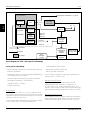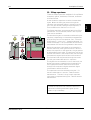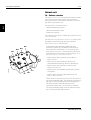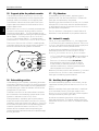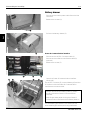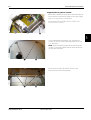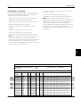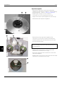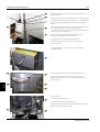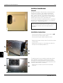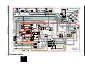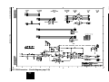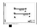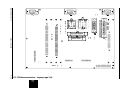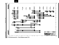
1
KION
Service Manual
E382 E392E 061 01 01 02
Important
KION
Important
General
Installation
• Documentation for the KION™ Anesthesia System
consists of:
– Operating Manual
– Service Manual
– Spare Parts List
– Documentation for the KION Display.
• Documentation for all optional equipment
included in the KION System is also available.
• Only personnel authorized by Siemens shall be
permitted to install the KION System. The
installation and handing over procedures are
described in the ”KION – Installation Instructions”.
• The Operating Manual is an indispensable complement to the Service Manual for proper servicing.
• A version label can be found by the mains power
inlet. This label is an ”Operating Manual version
label” indicating the version number of the
Operating Manual to be used with this KION
System.
• This information in this Service Manual is based
on the ”KION System Level 3.0”, that is:
– Units delivered from factory starting in
January 1999.
– Older units updated with the mandatory
”Update 1998-12”.
Text inside a box is used to highlight important
information.
Functional check and Calibration
• After any maintenance or service intervention in
KION, perform a ”Function check” and a ”Calibration” according to instructions in the KION –
Operating Manual.
Hazard notices
• Before disassembling or assembling the KION
System, make sure that the:
– Gas supply is disconnected.
– Mains power cable is disconnected.
– Power switch is set to Off. If the power switch
is set in any other position, the internal battery
will supply power to the PC boards.
– The back-up batteries are disconnected when
the power section is open.
– All gas conveying parts are cleaned according to
instructions in the KION - Operating Manual,
chapter Routine cleaning.
• In addition to the Important information given
here and in the related documents (e. g. in the
Operating Manual), always pay attention to
applicable local and national regulations.
• Responsibility for the safe functioning of the
equipment reverts to the owner or user in all
cases in which service or repair has been done by
a non-professional or by persons who are not
employed by or authorized by Siemens, and when
the equipment is used for other than its intended
purpose.
• Data on internal pressures in the KION are given
in Pa (bar).
Airway pressures are given in cm H2O (Pa).
1 hPa = 1 mbar
1 mbar = 1 hPa
1 kPa = 10 mbar
1 mbar = 0.1 kPa
1 kPa = 0.01 bar
1 bar = 100 kPa
1 kPa N 10 cm H2O
1 cm H2O N 0.1 kPa
1 kPa N 0.01 at
1 at N 100 kPa
1 kPa N 0.01 kgf/cm2
1 kgf/cm2 N 100 kPa
1 kPa N 0.01 kp/cm2
1 kp/cm2 N 100 kPa
1 kPa N 0.145 psi
1 psi N 6.9 kPa
0-2
Siemens-Elema AB
E382 E392E 061 01 01 02
KION
Important
Important
Service
To the responsible service personnel
• The KION Anesthesia System must be serviced at
regular intervals by personnel authorized by
Siemens. Any maintenance must be noted in a
log book provided in accordance with national
regulations. We recommend that service is done
as a part of a service contract with Siemens.
• The contents of this document are not binding.
If any significant difference is found between the
product and this document, please contact
Siemens for further information.
• Maintenance must be performed every:
– Six months. This corresponds to approx. 1.000
hours of operation calculated as operating time
of 40 hours a week during six months. Details
are found in the Operating Manual.
– Twelve months or every 3000 hours of
operation whichever comes first. Details are
found in this Service Manual, chapter
”Maintenance”.
– Three years. The internal battery shall be
replaced every three years according to
instructions in this Service Manual, chapter
”Maintenance”.
• Worn-out batteries must be returned
to the place of purchase or to a place
where they can be safely disposed of.
Batteries must not be disposed of
with ordinary waste. All other
disposable parts shall be discarded
according to hospital rules and in an
environmentally safe way.
• We reserve the right to modify products without
amending this document or advising the user.
• Only personnel authorized by Siemens shall be
permitted to service or repair the KION System.
Only Siemens-Elema genuine spare parts must
be used. PC boards (spare parts) must always be
kept in a package for sensitive electronic devices.
Siemens will not otherwise assume responsibility
for the materials used, the work performed or any
possible consequences of same.
0413
• The device complies with the
requirements of the Medical Device
Directive 93/42/EEC.
Pb
• When working with ESD sensitive components,
always use a grounded wrist band and a
grounded work surface. Adequate service tools
must always be used.
E382 E392E 061 01 01 02
Siemens-Elema AB
0-3
Important
KION
Notes
0-4
Siemens-Elema AB
E382 E392E 061 01 01 02
KION
Important
Contents
Contents
1. Introduction ...................................................................................................
1
2. Description of functions..............................................................................
2
3. Disassembling and assembling ................................................................
3
4. Service procedures......................................................................................
4
5. Troubleshooting............................................................................................
5
6. Maintenance .................................................................................................
6
7. Installation of optional equipment ............................................................
7
8. Diagrams ........................................................................................................
8
E382 E392E 061 01 01 02
Siemens-Elema AB
0-5
Important
KION
Notes
0-6
Siemens-Elema AB
E382 E392E 061 01 01 02
KION
Introduction
1. Introduction
Main units .........................................................
1-2
Battery drawer ...............................................
1-3
Pneumatic section ..........................................
1-4
Vaporizer section ............................................
1-5
Patient unit .....................................................
1-6
User interface .................................................
1-7
Optional equipment ...........................................
1-8
Overflow Screen ............................................
1-8
Multi-gas module ...........................................
1-8
Isolation Transformer .....................................
1-9
Backup Gas Supply Manifold .........................
1-9
Suction Equipment ......................................... 1 - 10
Auxiliary O2 Supply ......................................... 1 - 10
Gas evacuation ............................................... 1 - 11
Accessory shelf .............................................. 1 - 11
Monitor shelf .................................................. 1 - 11
Electronic structure ........................................... 1 - 12
General ........................................................... 1 - 12
Internal communication .................................. 1 - 13
E382 E392E 061 01 01 02
Siemens-Elema AB
1-1
1
Introduction
KION
Main units
The following optional equipment can also be
incorporated in the KION System:
• Battery drawer
• Overflow screen
• Pneumatic section
• Multi-gas module
• Vaporizer section
• Isolation transformer
• User interface, i. e. the Control panel and the KION
Display (a Siemens patient monitor intended for use
with the KION System, e. g. SC 7000, SC 9000 or SC
9000XL).
• Backup gas supply manifold
• Patient unit.
• Gas evacuation
All these main units are incorporated in or attached to
the trolley which is the main body of the system.
• Accessory and Monitor shelfs.
• Suction equipment
• Auxiliary O2 supply
Vaporizer section
Pneumatic section
User interface
Patient unit
Battery drawer
KN-0200E
1
The KION System can be divided into the following
functional main units:
1-2
Siemens-Elema AB
E382 E392E 061 01 01 02
KION
Introduction
Battery drawer
d
g
f
s
a
The battery drawer can be pulled out from the trolley
and thus easier to access. It contains functions for
power supply and communication:
1. AC/DC Converter
2. Internal battery. An optional Extra internal battery
can be installed to prolong the backup time.
Included in the Battery drawer is also the Power &
Communication interface containing:
3. Communication ports
4. PC 1747 CAN/RS232 INTERFACE (CAN = Controlled
Area Network)
5. PC 1753 DC/DC CONVERTER
KION9001
6. PC 1675 POWER SUPPLY
7. PC 1761 MIB CONNECTOR (MIB = Medical
Information Bus)
8. PC 1754 CONNECTOR BOARD
k
j
l
9. Communication interface including the small KION
Display identity board. These PC boards are also
included in the Siemens patient monitor Communication/Power Supply (CPS) module. For further
information, see documentation regarding the
Communication Power Supply module.
KION9002
h
;
The following cables are connected to the Power &
Communication interface :
10. Multi gas module communication cable (RS232)
A
11. Multi gas module power cable (24 V DC)
S
12. Overflow screen cable (RS232 & Supply Voltage)
13. CAN loop-back (Service Port)
D
14. KION Display communication cable (TAXI)
KION9017
15. AC/DC converter cable
F
H
E382 E392E 061 01 01 02
16. Isolation transformer cable (optional).
G
Siemens-Elema AB
1-3
1
Introduction
KION
Pneumatic section
d
The pneumatic section, accessible when the top
cover and shield cover is removed, controls the
inspiratory fresh gas flow and the expiratory gas flow.
1
The main functions are:
1. Gas distribution block with PC 1720 WALL PRESSURE
Inspiratory control with the:
2. Gas modules and PC 1765 VALVE
INTERCONNECTION
3. Inspiratory gas block
4. Fresh gas pressure container
KION9003
5. Inspiratory fresh gas flow transducer with
PC 1748 FRESH GAS FLOW
a
6. Inspiratory fresh gas valve with PC 1751 STEP
MOTOR.
f
7. PC 1750 TRANSDUCER
s
h
g
8. PC 1733 INTERCONNECTION
9. Expiratory valve
10. PC 1730 CONTROL
KION9004
11. PC 1737 MEASURING.
j
k
l
;
KION9130
A
1-4
Siemens-Elema AB
E382 E392E 061 01 01 02
KION
Introduction
Vaporizer section
a
d
The vaporizers used in the KION System are Presicion
Injection Vaporizers, PIVap.
The vaporizers are color-coded for the different
anesthetic liquids and filling is key-indexed.
Three vaporizers can be mounted onto the vaporizer
magazine. The main functions are:
1. Vaporizer magazine. The magazine can be
revolved to facilitate easy access to the active
vaporizer.
ALO030AX
2. PIVap vaporizers
3. Vaporizer locking lever
s
f
4. Vaporizer concentration knob. Only one vaporizer
can be active at a time due to the interlocking
system. To activate the vaporizer; push-in and
turn the vaporizer concentration knob counterclockwise.
Vaporizers for the following anesthetic agents are
available:
• Halothane
• Enflurane
• Isoflurane
• Sevoflurane.
Handle the vaporizers with care when filled with
anesthetic liquids. Never turn them upside down
or lay them sideways.
E382 E392E 061 01 01 02
Siemens-Elema AB
1-5
1
Introduction
KION
Patient unit
The patient unit controls the gas flow to and from the
patient. The main functions are:
d
1
1. Patient cassette. Removable unit containing
mushroom valves, expiratory flow transducer,
inspiratory and expiratory unidirectional valves
and the APL valve. The patient tubes and the
manual breathing bag are connected to the
patient cassette.
O2+
0
5L / min O 2
l
k
2. Support plate for patient cassette. There are five
solenoid valves and a mechanically controlled cutoff valve included in the support plate. The
solenoid valves are electrically connected to
PC 1755 PATIENT CASSETTE VALVE CONTROL.
j
a
3. Rebreathing section. The rebreathing bellows and
the bellows container are connected to the
breathing system when Circle System is
selected. A bellows top-position sensor (4)
including PC 1766 BNB SENSOR is mounted on the
trolley.
KN-S311X
5. The CO2 Absorber purifies the rebreathing gas
when Circle System is selected.
s
g
6. Auxiliary fresh gas outlet to be used in combination with external breathing systems such as
Bain.
h
7. The section Instant O2 supply contains the:
f
8. O2 Flush push-button (marked O2+).
A gas flow of approx. 50 l/min will be supplied
from the O2 gas supply to the breathing
system as long as this button is pressed.
9. Emergency O2 switch (marked 5 L/min O2).
When switched on, it secures a continuous
gas flow from the O2 gas supply of approx. 5
l/min. This function enables manual
ventilation, e. g. in case of ventilator
malfunction.
KION9005
s
1-6
Siemens-Elema AB
E382 E392E 061 01 01 02
KION
Introduction
User interface
s
Control panel
a
The control panel section consists of the:
1
1. Control panel housing.
2. Front panel in different language versions.
3. PC 1672 CONTROL PANEL.
KION9006
The control panel selectors and potentiometers are
mounted on the control panel housing.
KION9007
d
KION Display
a
The KION Display (1) used is a Siemens patient
monitor intended for use with the KION System, e. g.
SC 7000, SC 9000 or SC 9000XL. The KION Display,
that is mounted on the DOCKING STATION™, will in
combination with the Communication Interface, make
the KION System an integrated part of the Siemens
PICK AND GO™ concept.
ALO030BX
The KION Display is used not only for clinical information but also for displaying technical information e. g.
during pre-use check, calibration and troubleshooting
of the KION System.
E382 E392E 061 01 01 02
For information regarding the KION Display, see the
User's guides and the Service Manuals for the
Siemens Patient Monitors.
Siemens-Elema AB
1-7
Introduction
KION
Optional equipment
Overflow Screen
1
For additional monitoring capabilities, an Overflow
Screen (DUOVIEW) can be connected to the KION
System.
The DUOVIEW is a Surgical Display designed to be an
integrated part of the KION System. The DUOVIEW
contains the Surgical Display Controller and a VGA
Display.
KION7027
The DUOVIEW is controlled by the KION Display.
Multi-gas module
a
As an option, a Multi-gas module (1) can be installed
into the KION System. The module to be installed is a
modified version of the stand-alone Siemens
MULTIGAS+™ Module.
With the Multi-gas module installed, the
concentration of the following gases can be displayed
on the KION Display:
• O2 (measured by a fast-acting paramagnetic sensor)
• CO2
• N 2O
KION7038
• Anesthetic agent.
1-8
For information regarding the Multi-gas module, see
the Service Manual for the Siemens MULTIGAS+
Module.
Siemens-Elema AB
E382 E392E 061 01 01 02
KION
Introduction
Isolation Transformer
The KION System can be equipped with an optional
KION Isolation Transformer (1) containing four mains
power outlet connections and fuses for these
outlets. The isolation transformer is available in two
versions; 115 V and 230 V.
ITOM-02X
All equipment connected to the KION System in
patient care areas and clinical environments must be
separated from the power source by an isolation
transformer.
a
Backup Gas Supply Manifold
a
The KION System can be equipped with an optional
KION Backup Gas Supply Manifold (1) with PIN-index
gas connections for 4 gas cylinders.
The gas connections are intended for:
• N2O (one gas cylinder)
• AIR (one gas cylinder)
• O2 (two gas cylinders)
The manifold also contains:
2. Pressure regulators. One for each gas.
3. Pressure transducers. One for each gas.
KION9010
4. Safety valves. One for each gas.
s
d
f
KION9011
f
E382 E392E 061 01 01 02
Siemens-Elema AB
1-9
1
Introduction
KION
Suction Equipment
The main parts of the optional KION Suction
Equipment are:
1
a
1. The suction ejector that creates the vacuum.
The suction ejector is powered with drive gas
from the gas distribution block.
2. The suction bottle where the liquid is collected.
The Siemens 1.8 liters suction bottle is
recommended.
SEOM-00X
s
Auxiliary O2 Supply
For Auxiliary O2 Supply, an Auxiliary Oxygen
Flowmeter can be mounted onto the KION System.
The flowmeter is supplied with O2 from the gas
distribution block.
FLOM-00X
O2
1 - 10
Siemens-Elema AB
E382 E392E 061 01 01 02
KION
Introduction
Gas evacuation
For evacuation of anesthetic gases from the KION
System, the optional Servo Evac 180 can be
connected.
KION7056
1
Accessory shelf
KION7022
An optional accessory shelf can be mounted on the
KION System. It is not possible to mount the
accessory shelf if the KION System is already
equipped with a monitor shelf.
Monitor shelf
KION7024
An optional monitor shelf can be mounted on the
KION System. It is not possible to mount the monitor
shelf if the KION System is already equipped with an
accessory shelf.
E382 E392E 061 01 01 02
Siemens-Elema AB
1 - 11
Introduction
KION
Electronic structure
General
The KION software can be divided into the following
functional electronic subsystems:
• Panel (PAN)
• Alarm (ALA)
• Measuring (MEA)
• Multi-gas module interface (MGI)
• Monitor (MON)
• Control (CON)
• Power supply (PWR).
Measuring
MEA
Alarm
ALA
Control
CON
Panel
PAN
Multi-gas
module interface
MGI
Monitor
MON
Power supply
PWR
KION004E
1
1 - 12
Siemens-Elema AB
E382 E392E 061 01 01 02
KION
Introduction
Internal communication
The diagram below shows the basic electrical signals
between the different electronic subsystems:
1
CAN bus
Emergency line
Standby
ALA
PAN
MON
MEA
CPS Diagnostic
SC 9000 Diagnostic
VGA output
CIS (RS232)
Recorder
Infinity Network
MIB 1 & 2
RS232 Interface
MGI
CON
Mains power
Reset
PWR
= CAN node
Power outputs (Optional
isolation transformer)
CAN bus
Standby
Internal communication via CAN bus protocol.
Digital signal in separate cabel that activates standby
functions.
Emergency line
Digital signal in separate cabel for alarm distribution in
case of CAN bus malfunction.
E382 E392E 061 01 01 02
Reset
Digital signal in separate cabel that ensures a
controlled start of the microprocessors at a stable
voltage level.
Siemens-Elema AB
1 - 13
Introduction
1
KION
Panel (PAN)
Measuring (MEA)
The PAN-software is stored in an exchangable
program memory (PAN-PROM) mounted on
PC 1672 CONTROL PANEL.
The MEA-software is stored in an exchangable
program memory (MEA-PROM) mounted on
PC 1737 MEASURING.
The main functions of the PAN subsystem are:
The main functions of the MEA subsystem are:
• Forwarding panel settings to CON and MEA.
• Measuring, calculation and supervision of expiratory
flow (minute and tidal volume).
• Displaying set and measured parameters.
• Barometer calibration and forwarding of barometric
pressure.
• Measuring and supervision of airway pressure
(software and hardware detection).
• Supervision of gas supply pressure.
• Adjusting display brightness.
• Heating, calibration and zeroing of the expiratory
flow transducer.
• Supervision of ALA.
• Control panel check (displays and LEDs) at startup.
• Calibration of pressure transducers.
• Supervision of ”Disconnect”.
Alarm (ALA)
The measured values are distributed to the correct
subsystem via the CAN bus.
The ALA-software is stored in an exchangable
program memory (ALA-PROM) mounted on
PC 1672 CONTROL PANEL.
The main functions of the ALA subsystem are:
MEA handles alarm detection and forwards the
alarms to the ALA subsystem. Alarm limits are either
constant values or values set on the control panel.
• Alarm gateway; transfers alarms from the different
subsystems to the MON subsystem for
presentation on the KION Display.
Multi-gas module interface (MGI)
• Alarm backup in case of communication error with
the KION Display.
• System release at power-up.
The MGI-software is stored in an exchangable
program memory (MGI-PROM) mounted on
PC 1747 CAN/RS232 INTERFACE.
The main functions of the MGI subsystem are:
• Supervision of power supply.
• Supervision and calculation of battery capacity.
• Protocol converter between KION (CAN) and Multigas module (RS232).
• Supervision of system status (OFF/Standby/ON).
• Startup of Multi-gas module.
• Supervision of internal CAN-nodes.
• Handling E2PROM-data concerning system
configuration.
• Mains/battery indication on the control panel.
• Alarm silencing on the control panel.
1 - 14
Siemens-Elema AB
E382 E392E 061 01 01 02
KION
Introduction
Monitor (MON)
Power supply (PWR)
The Monitor (MON) subsystem includes the:
The Power supply (PWR) subsystem includes the:
• Communication interface (CPS Network PCB).
• AC/DC Converter.
• PC 1754 Connector.
• Internal battery.
• PC 1761 MIB Connector.
• PC 1753 DC/DC CONVERTER.
• KION Display.
• PC 1675 POWER SUPPLY.
The Communication interface including the small KION
Display identity board is also included in the Siemens
SC 9000 module Communication Power Supply (CPS).
• Isolation transformer (if connected).
The software, CPS-SW in the Communication
interface and KION DISPLAY-SW in the KION Display,
is installed from a PC Card via the KION Display.
The main functions of the MON subsystem are:
1
• Control of power up and power down sequences
The Power supply subsystem is responsible for
converting mains power and battery power to the
voltage levels requested by the system. Power
supply will also supply these voltages to the electrical
parts within the system.
• Displaying patient parameters and wave forms.
• Displaying gas supply pressures.
Multi-gas
module
interface
• Displaying set and measured gas concentrations.
• Displaying alarms.
MGI
Panel
PAN
• Handling external communication.
Monitor
MON
Control (CON)
The CON-software (CON-SW) is stored in a FLASHPROM on PC 1730 CONTROL.
The main functions of the CON subsystem are:
Alarm
Pneumatic
section
including
• Control of breathing systems.
ALA
MEA
and
• Control of ventilation modes.
CON
+24 V
• Control and measuring of fresh gas flow including
gas mixture selection (O2/AIR, O2/N2O).
+12 V
-15 V
+15 V
Power supply
+5 V
PWR
-12 V
+13 V
GND
• Calculation of inspiratory flow.
• Calculation of spontaneous breathing frequency.
+24 V_VALVE
For supervision purposes
• Conversion of panel settings and feedback to panel.
• Controlling the ”Pre-use check” and the
”Calibration” sequences.
• Control of all electromagnetic valves.
E382 E392E 061 01 01 02
Siemens-Elema AB
1 - 15
Introduction
KION
Notes
1
1 - 16
Siemens-Elema AB
E382 E392E 061 01 01 02
KION
Description of functions
2. Description of functions
Battery drawer .................................................. 2 - 2
1. AC/DC Converter .....................................
2-2
2. Internal battery ......................................... 2 - 2
3. Extra internal battery (optional) ................
2-3
4. Power & Communication interface ..........
2-3
Pneumatic section .............................................
2-6
5. Gas distribution block ...............................
2-6
6. Inspiratory control ....................................
2-7
7. Expiratory valve ........................................ 2 - 10
8. PC 1733 Interconnection .......................... 2 - 11
9. PC 1730 Control ....................................... 2 - 11
10. PC 1737 Measuring .................................. 2 - 16
11. PC 1750 Transducer ................................. 2 - 18
Vaporizer section ............................................... 2 - 18
12. Vaporizer magazine .................................. 2 - 18
13. PIVap vaporizers ....................................... 2 - 19
Patient unit ........................................................ 2 - 20
14. Patient cassette ....................................... 2 - 20
15. Support plate for patient cassette ............ 2 - 22
16. Rebreathing section ................................. 2 - 22
17. CO2 Absorber ........................................... 2 - 22
18. Instant O2 supply ...................................... 2 - 22
19. Auxiliary fresh gas outlet .......................... 2 - 22
User interface .................................................... 2 - 23
20. Control panel ............................................ 2 - 23
21. KION Display .............................................. 2 - 23
Optional equipment ........................................... 2 - 23
22. Overflow screen....................................... 2 - 23
23. Multi-gas module ..................................... 2 - 24
24. Isolation transformer ................................ 2 - 24
25. Backup gas supply ................................... 2 - 24
26. Suction equipment ................................... 2 - 25
27. Auxiliary O2 supply ................................... 2 - 25
28. Gas evacuation ......................................... 2 - 25
E382 E392E 061 01 01 02
Siemens-Elema AB
2-1
2
Description of functions
KION
About this chapter
2. Internal battery
This functional description is divided in two levels:
The INTERNAL BATTERY (two serial connected 12 V
sealed lead acid batteries) supplies the KION System
with backup power for min. 30 minutes with full
loaded battery.
Basic principles containing a survey of the function.
This text is written with an italic typeface.
The text refers to the diagram ”Basic principles”
in chapter 8. ”Diagrams”.
2
Enhanced information about the function. Normal
typeface is used in this text. This text refers to the
following diagrams in chapter 8. ”Diagrams”:
The INTERNAL BATTERY is used as an internal 24 V
backup. The batteries are rated 12 V, approx. 24 Ah.
Tested batteries for use in KION are:
• HITACHI HP24-12
• ”Pneumatic section”
• VARTA, Type accu-CF
• ”Patient unit and vaporizer section”
• NEWMAX, Type FNC 12240
• ”Electronic interconnection”.
• CSB, Type EVX-12260.
Text written in SMALL CAPS refers to block names in
the diagrams mentioned above.
No other batteries must be used.
Battery drawer
The battery drawer contains functions for power
supply and communication.
1. AC/DC Converter
The INTERNAL BATTERY is continously charged when the
KION System is connected to mains power. Charging
time for empty batteries is approx. 6 hours.
The actual INTERNAL BATTERY capacity is continously
displayed on the KION Display. The battery capacity
indication, bargraph with %, is related to actual
battery voltage. ”100%” is indicated when trickle
charge level is reached (fully charged).
The AC/DC CONVERTER, containing the mains power
rectifier and the transformer, is a complete unit that is
mounted on the Power & Communication interface
casing. The AC/DC CONVERTER is electrically connected
to PC 1675 POWER SUPPLY.
The following applies concerning battery voltage
supply:
There are two mains power inlet fuses in the AC/DC
CONVERTER. The fuses and the AC/DC CONVERTER FAN
are the only spare parts available for the AC/DC
CONVERTER.
• If the AC/DC CONVERTER output voltage is below
19 V (e.g. at loss of mains power), a ”Switching to
battery” alarm indicates that battery voltage supply
is in use.
The AC/DC CONVERTER FAN pulls cooling air into the
converter compartment. If the fan fails, the signal
FAN_FAIL generates a diagnostic log message.
• First battery alarm ”Limited battery capacity” is
activated when battery voltage reaches below 23 V
or 22 V if an EXTRA INTERNAL BATTERY is connected.
These voltage levels correspond to ”20%”
indicated.
If the AC/DC CONVERTER is overheated (above +90°C /
194°F), e. g. due to fan failure, the AC/DC CONVERTER
will be disabled. The KION SYSTEM will then be power
supplied by the INTERNAL BATTERY. When the AC/DC
CONVERTER cools down, it will automatically be enabled.
Technical data for the AC/DC CONVERTER:
• AC/DC CONVERTER input: 100 – 240 V AC, 50 – 60 Hz.
• AC/DC CONVERTER output: Max. 400W, ouput voltage
level 21 – 30 V DC controlled by analog signal from
the Charging/Discharging control block on PC 1675
POWER SUPPLY.
• Battery voltage supply is used as soon as the
AC/DC CONVERTER voltage is less than the battery
voltage (e.g. at loss of mains power).
• Second battery alarm ”No battery capacity” is
activated 10 minutes after first battery alarm or
when battery voltage is below 22 V or 21.5 V if an
EXTRA INTERNAL BATTERY is connected. These voltage
levels correspond to ”0 %” indicated.
• All functions will be cut off when battery voltage
reaches below 21 V.
Battery capacity indication and alarms are generated
via the ALA power supervision function.
• Fuses: T 6.3 AL / 250 V AC (2 pcs).
2-2
Siemens-Elema AB
E382 E392E 061 01 01 02
KION
Description of functions
Service interval for the INTERNAL BATTERY:
Communication ports – PC 1754 Connector
• The INTERNAL BATTERY must be checked during the
”Twelve months maintenance”.
Communication ports for connecting the KION System
to network, service options, etc. The communication
ports are integrated parts of PC 1754 CONNECTOR.
• The INTERNAL BATTERY must be replaced every three
years. After replacement, allow the batteries to
recharge before clinical use of the Kion System.
The lifetime of the INTERNAL BATTERY is reduced if it is
used frequently to supply the KION System with
operating power or if the battery temperature is above
+50°C (122°F) e. g. due to BATTERY DRAWER FAN failure.
In such case, it is recommended to check the INTERNAL
BATTERY with shorter intervals than 12 months.
3. Extra internal battery (optional)
Pin configuration and signal names can be found in
chapter 8 ”Diagrams”.
PC 1761 MIB Connector
2
The PC 1761 MIB CONNECTOR converts monitoring
parameters to MIB protocol. (MIB = Medical
Information Bus.)
Pin configuration and signal names can be found in
chapter 8 ”Diagrams”.
Communication interface (CPS network PCB)
EXTRA INTERNAL BATTERY (two serial connected 12 V
sealed lead acid batteries) for extended backup time.
Gives, together with the INTERNAL BATTERY, a total
backup time of approx. 120 minutes with full loaded
battery.
For information regarding battery type, function and
service interval, see section 2. ”Internal battery”
above.
There are two versions of the battery cable; one
version to be used if a standard INTERNAL BATTERY is
connected and one version to be used if an EXTRA
INTERNAL BATTERY is connected. Thus, if an extra EXTRA
INTERNAL BATTERY is connected (or disconnected), the
battery cable must be replaced.
4. Power & Communication Interface
The following functions are included in the POWER &
COMMUNICATION INTERFACE:
• Communication ports – PC 1754 CONNECTOR.
• PC 1761 MIB CONNECTOR.
Communication interface including the small KION
display identity board. These PC boards are also
included in the Siemens patient monitor
Communication/Power Supply (CPS) module.
The CPS-software (CPS-SW) is installed from a
PC Card via the SC 7000 / SC 9000 / SC 9000XL.
PC 1747 CAN/RS232 Interface
Protocol converter between KION (CAN) and MULTI GAS
MODULE (RS232).
The MGI-software is stored in an exchangable
program memory (MGI-PROM) mounted on PC 1747
CAN/RS232 INTERFACE.
PC 1753 DC/DC Converter
This description also refers to the block diagram
”Power supply – Main functions” below.
PC 1753 DC/DC CONVERTER is supplied with +24 V
from PC 1675 POWER SUPPLY and generates:
• COMMUNICATION INTERFACE (CPS network PCB).
• +12 V to connected equipment (lamp, recorder,
MIB, CPS Diagnostic and Overflow screen).
• PC 1747 CAN/RS232 INTERFACE.
• +13 V to the KION Display.
• PC 1753 DC/DC CONVERTER. Generates +12 V, +13 V
and a fused +24 V for power supply of the KION
System.
• A fused +24 V to the MULTI GAS MODULE.
• PC 1675 POWER SUPPLY. Voltage supply and battery
charge/capacity check. Generates +15 V, - 15 V and
+5 V.
• BATTERY DRAWER FAN.
E382 E392E 061 01 01 02
Siemens-Elema AB
2-3
Description of functions
2
KION
There are three fuses on PC 1753:
Battery Drawer Fan
• F1/PC 1753 = 15 A / 32 V. Cuts the +24 V power
supply to the DC/DC CONVERTER 24/12 V which
disables the +12 V power supply to connected
equipment. No alarm is activated.
The BATTERY DRAWER FAN pulls air out of the battery
drawer compartments. If the fan fails, the signal
FAN_FAIL generates a diagnostic log message.
• F2/PC 1753 = 15 A / 32 V. Cuts the +24 V power
supply to the DC/DC CONVERTER 24/13 V which
disables the +13 V power supply to the KION
Display. The KION Display will run on its internal
battery and alarm is activated.
If the temperature in the battery drawer compartment
is above 45 – 50°C (113 – 122°F), e. g. due to BATTERY
DRAWER FAN failure, the function of the MULTI GAS
MODULE and the lifetime of the INTERNAL BATTERY may
be affected.
• F3/PC 1753 = 7.5 A / 32 V. Cuts +24 V power
supply to the MULTI GAS MODULE. Alarm is activated.
PC 1675 Power Supply
This description also refers to the block diagram
”Power supply – Main functions” below.
The main functions are:
• Generates and distributes +15 V, - 15 V and +5 V to
the different KION subsystems. Also generates
+12 V and -12 V for the COMMUNICATION INTERFACE
(CPS) via linear regulators.
• The Logic & Timing block handles different time
delays for voltages at Power On:
– The input signal MEAS_INHIBIT comes from ALA
in order to stop the battery capacity check.
– The input signal DISABLE_VALVES comes from
ALA, CON or MEA in order to disable
+24 V_VALVE (stop power supply to gas
modules) e.g. at upper pressure alarm.
• Power supply to gas modules, +24V_VALVE, will
also be cut at Low battery voltage or at System Off.
• BATTERY DRAWER FAN is power supplied by +24V_FAN.
• Power supervision function in the ALA subsystem
and PATIENT CASSETTE VALVE CONTROL is power
supplied by +24V_PTC.
• Battery status and measure signals from the block
Charging/Discharging control is supplied to ALA.
• Power supply of the system will be cut at Low
battery voltage or at System Off.
There are two fuses on PC 1675:
• F1/PC 1675 = 30 A / 32 V. Battery short-circuit
protection. The internal battery is disconnected and
alarm is activated.
• F2/PC 1675 = 20 A / 32 V. Protects the internal
battery from failures on PC 1675. The internal
battery is disconnected and alarm is activated.
2-4
Siemens-Elema AB
E382 E392E 061 01 01 02
KION
Description of functions
PC 1675 Power Supply
FAN_FAIL_AC_DC
Fan logic
FAN_SENSE.
FAN_FAIL.H
(ALA)
POWER_DOWN.L
MAINS.H H
Battery measuring control
MEAS_INHIBIT.H
(ALA)
POWER_ON_RESET.L
Logic &
Timing
Time delay
switch
+24V_VALVE
Time delay
switch
+24V_FAN
2
Control of valve voltage
DISABLE_VALVES.L
Operator
Reg
PTC
ON/OFF
On/Off switch
+24V_PTC
+24V_PSU_SWITCH
PSU_ON.H24
+15 V
DC/DCconverter
+15/-15/+5 V
-15 V
+5 V
Reg
F2 / 20 A
Reg
F1 / 30 A
+12 V
CPS
-12 V
CPS
BATT_LARGE.L
DISCHARGE.H
Charging/
Discharging
control
BATT_CYCLE.H
DISCHARGE_CURRENT
CHARGE_CURRENT
Status
and
measure
signals
to ALA
BATT_VOLTAGE
F2 / 15 A
DC/DCconverter
24/12 V
DC/DCconverter
24/13 V
+13 V
+12 V
(KION Display)
(Lamp)
+12 V @ 1,8 A (2 pcs) (Recorder)
Current limiter
F1 / 15 A
+12 V @ 0,32 A (2 pcs) (MIB)
Current limiter
+12 V @ 0,42 A (CPS Diagnostic)
Current limiter
+12 V @ 1,3 A (Overflow Screen)
Current limiter
PC 1753
DC/DC
Converter
F3 / 7.5 A
+24 V (MGM)
Battery
Mains power
Battery selector
Temp. sensor
AC/DC
converter
Block diagram: Power supply – Main functions
E382 E392E 061 01 01 02
Siemens-Elema AB
2-5
Description of functions
KION
Pneumatic section
Gas selection valves
5. Gas distribution block
The different gases delivered to the GAS MODULES are
controlled as follows in the GAS DISTRIBUTION BLOCK:
Gas supply from hospital central gas supply and/or
from gas cylinders are connected to this block.
The main functions are:
• Three gas inlets to connect gas from the hospital
central gas supply.
2
• PC 1720 WALL PRESSURE mounted on the block
measures the hospital central gas supply pressures.
• The breathing gas and drive gas delivered to the
KION System subunits are electronically and
pneumatically controlled by the GAS SELECTION
VALVES.
• The two preset pressure regulators mounted on the
GAS DISTRIBUTION BLOCK regulates the pressure in the
gases delivered to the patient cassettes mushroom
valves and to the block INSTANT O2 SUPPLY.
• A number of gas inlets and outlets for connection of
optional equipment to the KION System.
Gas inlets
Three quick-couplings to connect gas from the
hospital central gas supply. The design of the gas
inlet nipples and the color marking of the inlets varies
according to different national standards. The gas
inlet channels (inside the gas distribution block) are
equipped with gas inlet filters and spring loaded oneway valves, OV1 – OV3. The filters must be replaced
during the ”Twelve months maintenance”.
PC 1720 Wall Pressure
There are two main functions on PC 1720 WALL
PRESSURE:
• Three pressure transducers including amplifiers.
Measures the pressure in the gases connected to
the gas inlets (from the hospital central gas supply).
There are no tube connections to the transducers,
the PC board is mounted firmly onto gas outlets in
the GAS DISTRIBUTION BLOCK. The gas outlets are
equipped with seals to prevent leakage between
the GAS DISTRIBUTION BLOCK and the PC board.
• Gas going to GAS MODULE AIR (N2O) – BP:
Controlled by the solenoid valve EMV6. AIR or N2O
breathing gas depending on settings on the control
panel. Cuts automatically the N2O supply if O2
supply pressure drops below 200 kPa (2.0 bar).
• Gas going to GAS MODULE O2 – BP: Only O2.
The O2 breathing gas is delvered directly to the
GAS MODULE O2 – BP and is not controlled by any
solenoid valve on the GAS DISTRIBUTION BLOCK.
• Gas going to GAS MODULE – DRIVE GAS – AIR (O2):
Controlled by the solenoid valve EMV7. Supplies
normally AIR but changes automatically to O2 if the
AIR supply pressure drops below 200 kPa (2.0 bar)
or if the solenoid valve drive voltage fails.
Pressure regulators
There are two preset pressure regulators mounted on
the GAS DISTRIBUTION BLOCK:
• REG1 regulates the pressure in the mushroom
valve control gas supply (AIR or O2 depending on
EMV7 mode) used by EMV1 – 5. The preset
pressure is 20 kPa ( 0.2 bar).
• REG2 regulates the pressure in the breathing gas
(O2 ) to the block INSTANT O2 SUPPLY. The preset
pressure is 250 kPa ( 2.5 bar).
Backup gas inlets
The GAS DISTRIBUTION BLOCK is equipped with three
backup gas inlets used when gases from the optional
BACKUP GAS SUPPLY MANIFOLD are connected. These
inlets are plugged if not used.
Gas outlets for auxiliary equipment
There are two extra gas outlets on the GAS
DISTRIBUTION BLOCK, one for O2 and one for AIR. These
outlets can be used to supply optional equipment,
such as AUXILIARY O2 SUPPLY and SUCTION EQUIPMENT,
with O2 and AIR.
• Valve driver, a drive stage for the gas selection
valves EMV6 and EMV7.
2-6
Siemens-Elema AB
E382 E392E 061 01 01 02
KION
Description of functions
6. Inspiratory control
Controls the gas delivered to the breathing system.
The main functions are:
• The three GAS MODULES. They are basically of the
same design and function as the gas modules
(inspiratory valves) in the Servo Ventilator 300.
• Four safety valves, SV1 – 4.
• FRESH GAS PRESSURE CONTAINER to create the working
pressure for the fresh gas supply.
The GAS MODULES are factory calibrated.
The adjustment potentiometer located at the top
of each GAS MODULE (Version A) must not be
adjusted.
Each GAS MODULE must not be disassembled
further than described in chapter 6 ”Twelve
months maintenance”.
• Inspiratory fresh gas channel that measures and
controls the fresh gas to the breathing system.
4
3
2
2
5
Gas modules
There are two different versions of the gas module:
• Version A recognized by the metal nozzle unit.
1
• Version B recognized by the plastic nozzle unit.
Version B will replace Version A in the production of
KION Systems during the second half of 1999. Date
and/or Serial No. for this change in production is not
yet descided. If not stated otherwise, this functional
description is valid for both versions.
• GAS MODULE AIR (N2O) – BP supplies AIR or N2O to
the VAPORIZER MAGAZINE.
• GAS MODULE O2 – BP supplies O2 to the VAPORIZER
MAGAZINE.
• GAS MODULE – DRIVE GAS – AIR (O2) supplies AIR or
O2 as drive gas to the REBREATHING SECTION.
The GAS MODULES marked BP are modified to handle
the backpressure created when supplying fresh gas
to vaporizers. Max. flow from the gas modules
modified for backpressure is reduced to 2 l/s.
The modification concerns PC boards inside the gas
module and the nozzle unit. Without these modifications, the backpressure would disable the diaphragms
closing function.
The GAS MODULES are pneumatically connected to the
INSPIRATORY GAS BLOCK and electrically connected to
PC 1765 VALVE INTERCONNECTION.
KNS1013X
6
The three GAS MODULES are:
1. Bacteria filter
2. Inspiratory valve temperature sensor
3. Supply pressure transducer
4. Flow transducer (Delta pressure transducer and net)
5. Nozzle unit with valve diaphragm
6. Inspiratory solenoid
Air inlet
Gases from the GAS DISTRIBUTION BLOCK are connected
to the inlet tube connectors on the GAS MODULES. The
tube connectors and the corresponding tubes have
different diametres to prevent faulty gas connections.
The filter housing and the filter cover is provided with
matching guide pins. These guide pins prevents
mounting the filter cover (with inlet tube connectors)
on wrong GAS MODULE.
A non-return valve for the gas inlet is located in the
inlet filter cover. This valve will suppress short
pressure drops in the gas supply. The non-return
valve is also designed to slowly evacuate
compressed gas from the GAS MODULE if the gas
supply to the GAS MODULE is disconnected.
E382 E392E 061 01 01 02
Siemens-Elema AB
2-7
Description of functions
KION
Bacteria filter
The bacteria filter protects the system from bacteria
and particles in the gas delivered to the air inlet.
The bacteria filter must be replaced during the
”Twelve months maintenance”.
2
Inspiratory valve temperature sensor
The temperature of the supplied gas is measured by
the inspiratory valve temperature sensor. This sensor
is situated in the gas flow.
The output signal from this sensor is used to
compensate for the gas density variations due to
temperature.
Supply pressure transducer
The pressure of the supplied gas is measured by the
supply pressure transducer.
The output signal from this transducer is amplified. It
is then used to calculate the absolute pressure of the
gas to compensate for gas density variations due to
pressure.
Delta pressure transducer and net
The gas flows through a net (resistance) which
causes a pressure drop. The pressure is measured on
both sides of this net and the differential pressure
value is then amplified.
Nozzle unit
The nozzle unit contains a valve diaphragm. The valve
diaphragm, controlled by the inspiratory solenoid,
regulates the gas flow through the GAS MODULE.
Metal nozzle units (Version A) modified for backpressure must be used together with a small washer
that is places on top of the inspiratory solenoid. This
washer will support the diaphragm and distributes
the backpressure over a larger area on the diaphragm.
This function is integrated in the plastic nozzle units
(Version B) and the small washer is not used in these
GAS MODULES.
Inspiratory solenoid
The gas flow through the GAS MODULE is regulated by
the inspiratory solenoid via the nozzle unit.
The current supplied to the solenoid is regulated so
that the gas module will deliver a gas flow according
to the front panel settings.
Gas module key
The GAS MODULES are provided with a mechanical key
to prevent that the GAS MODULE is mounted in the
wrong slot.
The key consists of a plastic guide mounted underneath the GAS MODULE and a corresponding guide
mounted on the pneumatic section base.
Safety valves
The INSPIRATORY CONTROL block contains four safety
valves:
• SV1 is a spring loaded valve preset to open at 180
kPa (1.8 bar). Protects the vaporizers in case of
failure in the GAS MODULES AIR (N2O) – BP
or O2 – BP.
• SV2 is a magnetic valve preset to open at 14 kPa
(140 mbar). Will release overpressures created in
the REBREATHING SECTION, e. g. if the patient is
coughing. Will also protect the REBREATHING SECTION
in case of failure in the GAS MODULE – DRIVE GAS –
AIR (O2).
• SV3 is a magnetic valve preset to open at 18 kPa
(180 mbar). Protects the FRESH GAS PRESSURE
CONTAINER and the INSPIRATORY FRESH GAS VALVE.
• SV4 is a magnetic valve preset to open at 14 kPa
(140 mbar). Protects the patient from high pressure
in the fresh gas.
The magnetic valves (SV2 – SV4) contain a permanent
magnet that affects the metal valve cone. The distance
between the magnet and the valve cone is preset to
open the valve when the pressure limit is reached.
The nozzle units are provided with a mechanical key
to prevent that the nozzle unit is mounted into wrong
GAS MODULE.
An O-ring and the valve diaphragm (Version A) or the
complete plastic nozzle unit (Version B) must be
replaced during the ”Twelve months maintenance”.
After replacement, allow the diaphragm to settle
during approx. 10 minutes before gas pressure is
connected to the GAS MODULE.
2-8
Siemens-Elema AB
E382 E392E 061 01 01 02
KION
Description of functions
Fresh gas pressure container
The fresh gas from the VAPORIZER MAGAZINE enters the
FRESH GAS PRESSURE CONTAINER above the big rubber
diaphragm mounted inside the container. A piston,
that is pushed up by the constant gas pressure
regulated by REG3, affects the diaphragm and the
fresh gas is pushed out from the FRESH GAS PRESSURE
CONTAINER. The preset pressure on REG3 is 100 kPa
(1.0 bar).
PC 1752 DIAPHRAGM POSITION SENSOR inside the
container, in combination with two magnetic washers
inside the piston, indicates the position of the piston,
i. e. if the container is full. This level signal is used to
enable and to disable the GAS MODULES for a flow of
fresh gas to the vaporizers.
The diaphragm and the piston seal must be replaced
during the ”Twelve months maintenance”.
Inspiratory fresh gas flow transducer
The gas flows through the flow transducer in two
parallel channels, one large main channel and one
small measuring channel. The main channel is fitted
with a wire mesh net, the resistance of which causes
a certain proportion of the gas to flow through the
measuring channel. The flow through and the
differential pressure across the measuring channel
acts on a small metal disc (”flag”) which, via a metal
pin, presses on a small semiconductor strain gauge.
This strain gauge consists of diffused resistors on
both sides of an elastic silicone rod. The resistors are
connected as a part of a Wheatstone bridge, the
other part of which is situated on PC 1748 FRESH GAS
FLOW. The more flow in the channel, the higher the
pressure on the strain gauge. The change in
resistance in the Wheatstone bridge is converted to a
corresponding signal voltage.
Cleaning of the flow transducer is described in
chapter ”Routine cleaning” in the Operating Manual.
Inspiratory fresh gas channel
The fresh gas passes:
• The inspiratory fresh gas flow transducer with
PC 1748 FRESH GAS FLOW (amplifier).
• The INSPIRATORY FRESH GAS VALVE with PC 1751 STEP
MOTOR (control function).
• The one-way valve OV4.
O2 from the block INSTANT O2 SUPPLY is connected to
the channel for fresh gas to breathing system in the
INSPIRATORY GAS BLOCK.
E382 E392E 061 01 01 02
Siemens-Elema AB
2-9
2
Description of functions
2
KION
Inspiratory Fresh Gas Valve with PC 1751 Step Motor
The INSPIRATORY FRESH GAS VALVE is operated by a step
motor with a special shape slotted cam mounted on
the motor shaft.
7. Expiratory valve
The gas flows through the fresh gas valve tube
(silicone rubber) that is a part of the inspiratory fresh
gas channel. The gas flow through the valve tube is
then controlled by a movable lever arm that squeezes
the valve tube against a fixed arm. This movable arm
is attached to the cam and transfers the step motors
rotation to a controlled opening position of the valve
tube.
The EXPIRATORY VALVE comprises a spring loaded pull
magnet acting on a lever arm which squeezes the
expiratory valve tube (silicone rubber) against a fixed
arm. The more the magnet is activated, the more the
valve will move towards the closing position.
The change in flow through the valve tube is microstep controlled by the step motor. The step motor is
controlled by PC1751 that is a part of the step motor
assembly.
PC1751 STEP MOTOR is equipped with two LEDs and
two photo detectors. When the step motor reaches
either end position of the cam slot, the light beam
between the LED and the corresponding photo
detector is interrupted by a cam screen. The cam
screen is a part of the slotted cam mounted on the
motor shaft. This will generate an end position signal
from PC 1751.
The expiratory gas flow is controlled by the EXPIRATORY
VALVE. This valve also controls PEEP if a PEEP
pressure is set on the CONTROL PANEL.
When power supply to the magnet is switched off,
the valve will be fully opened because of the spring.
This ensures that the patient always can exhale
through the ventilator at a power failure.
The expiratory valve is controlled by CON. At a PEEP
setting, information from the PEEP pressure transducer is used to regulate the valve position during
expiration.
The expiratory valve tube must be replaced during
the ”Six months maintenance” and the ”Twelve
months maintenance”.
The position of the LEDs / detectors in relation to the
cam screen is very important. If a LED / detector gets
out of position, or if they fail, this will cause the step
motor to ”rattle” because end positions are not
properly indicated.
When power supply to the INSPIRATORY FRESH GAS VALVE
is switched off (or if the power supply fails), the step
motor will always end up with the inspiratory valve in
fully opened position.
The fresh gas valve tube must be replaced during the
”Six months maintenance” and the ”Twelve months
maintenance”.
2 - 10
Siemens-Elema AB
E382 E392E 061 01 01 02
KION
Description of functions
8. PC 1733 Interconnection
9. PC 1730 Control
The PC 1733 INTERCONNECTION electrically connects a
number of units in the KION System. The only electronic functions on this PC board are output filters
and PTC resistors.
Controls flow, pressure, composition and concentration in the gas delivered to the patient. All ventilation
mode functionality is controlled by this unit.
Three PC boards are mounted in PC board connectors
on the upper side of the PC 1733:
PC 1730 CONTROL contains a microprocessor that
executes the CON-software (CON-SW) that is stored
in a FLASH-PROM.
• PC 1730 CONTROL
The main functions of PC 1730 CONTROL are:
• PC 1737 MEASURING
• General parameters (used or created by CON).
• PC 1750 TRANSDUCER
• Fresh gas production (excluding control of
anesthetic agent type and concentration).
The under side of PC 1733, accessible behind a
trolley cover, contains cable connectors for the:
2
• Inspiratory fresh gas control.
• Patient unit cable.
• Drive gas for rebreathing.
• Pneumatic section cable.
• Regulation of expiration.
• Control panel cable.
• Pressure transducers on the optional BACKUP GAS
SUPPLY MANIFOLD.
The PC board inputs/outputs are described in chapter
8. ”Diagrams”.
General parameters
Some of the general parameters used or created by
CON are:
• Pressure: Input pressure signals from the four
pressure transducers on PC 1750 are supplied via
the A/D CONVERTER for regulation of inspiration and
expiration.
• Timing: Output Insp. time and Exp. time signals
are generated. These are used by MEA to control
zeroing of the flow transducers.
• Fresh gas outlet: Input signal from the Hall sensor
in the AUXILIARY FRESH GAS OUTLET indicates when the
valve is opened. This signal is used to light up a
LED on the CONTROL PANEL.
• Pressure alarm: Input signal from MEA indicating
that upper pressure limit is reached. Used to stop
inspiration time and immediately start expiration
time. This will open the EXPIRATORY VALVE and to set
the other valves in safe positions.
E382 E392E 061 01 01 02
Siemens-Elema AB
2 - 11
Description of functions
KION
Air
Gas selection
EMV 6
Air / N2O
Gas supply
Valve position
N2O
Air / N2O
Gas module
AIR (N2O)-BP
Flow ref.
Bar. ref
Zeroing
2
Fresh
gas to
vaporizer
Vaporizer
Fresh
gas from
vaporizer
Fresh gas
pressure
container
Diaphragm
position
sensor
Gas module
O2-BP
O2
PC 1730 Control
A/D
converter
Gas flow
Parallell
I/O
Flow ref.
Bar. ref
Zeroing
Fresh
gas from
vaporizer
Inspiratory
fresh gas
control
Level
D/A
converter
Processor
Gas flow
(CON-SW)
Signal
Pulse
width
modulator
CAN bus
CANinterface
PCB
Block diagram: PC 1730 – Fresh gas production
Gas Modules
Two of the GAS MODULES delivers fresh gas to
vaporizers according to the O2 concentration set on
the CONTROL PANEL.
Fresh gas production
Fresh gas production depends on the following
settings:
• Selection of gas mixture – O2/Air or O2/N2O.
• Preset O2 concentration.
The control signals, delivered from the D/A converter
on PC 1730 CONTROL to the GAS MODULES, are:
• Anesthetic agent – type and concentration.
• Flow reference (ATP signal).
• Barometric pressure reference.
Air/N2O selection
Information about gas combination selected on the
CONTROL PANEL, O2/Air or O2/N2O, is distributed via the
CAN bus to PC 1730 CONTROL.
The electrically and pneumatically operated EMV 6
activates the selection. The switching of EMV 6 is
monitored.
2 - 12
• Zeroing of flow transducer.
Each GAS MODULE creates its gas flow signal which is
sent back to PC 1730 CONTROL.
Fresh Gas Pressure Container
The level signal from the DIAPHRAGM POSITION SENSOR
indicates if the FRESH GAS PRESSURE CONTAINER is empty.
This indication is used to enable and to disable the
GAS MODULES for a flow of fresh gas to vaporizers.
Siemens-Elema AB
E382 E392E 061 01 01 02
KION
Description of functions
Instant O2 supply
Fresh
gas flow
transducer
Flow regulated fresh
gas from vaporizer
Fresh
gas
production
Inspiratory fresh gas valve
with PC 1751 Step motor
Control
electronics
Fresh
gas
valve
Transducer
electronics
Fresh gas
to breathing
system
2
End pos.
indicator
Range selection
E2-Pot:s
PC 1730 Control
PC 1748 Fresh gas flow
Flow signal x 1
Flow signal x 50
Flow signal x 200
A/D
converter
Processor
Gas flow
(CON-SW)
Signal
Parallell
I/O
D/A
converter
Speed
Pulse
width
modulator
CANinterface
PC board
Direction
CAN bus
Block diagram: PC 1730 – Inspiratory fresh gas control
Inspiratory fresh gas control
Inspiratory fresh gas control depends on the following
settings:
• Volume – When non-rebreathing system is
selected.
• Fresh gas flow – When rebreathing system is
selected.
The fresh gas flow is also affected by the Instant O2
Supply (if O2 FLUSH or EMERGENCY O2 is activated).
Non-rebreathing mode
The INSPIRATORY FRESH GAS VALVE acts as an inspiratory
valve which delivers the total inspiratory gas flow as
set on the CONTROL PANEL (Volume).
Rebreathing mode
The INSPIRATORY FRESH GAS VALVE delivers fresh gas
flow, as set on the CONTROL PANEL, to be added to the
expiratory gas that is used for rebreathing (normally
after it has been purified in the CO2 ABSORBER).
E382 E392E 061 01 01 02
Regulation
A fresh gas flow reference signal (desired value) is
distributed via the CAN bus. The CON-SW compares
this value with the measured flow (actual value)
generated by the fresh gas flow transducer via
PC 1748 FRESH GAS FLOW. The signal output from
PC 1748 is a MUX that gives the flow signal 3
different levels of amplification:
• Flow signal x 1
• Flow signal x 50
• Flow signal x 200
A range selection signal is used to select amplification
level of flow signal.
As a result of the comparison, control signals (Speed
and Direction) are distributed to the INSPIRATORY FRESH
GAS VALVE via PC 1751 STEP MOTOR. If the step motor
in the fresh gas valve has reached an end position,
these control signals are disabled by an end position
signal from PC 1751 which prevents it from moving
further in the same direction.
Siemens-Elema AB
2 - 13
Description of functions
KION
Mushroom valves MV1 - 5 (+24 V)
PC 1730 Control
A/D
converter
Parallell
I/O
PC 1750
Transducer
Air
2
Processor
(CON-SW)
D/A
converter
Pulse
width
modulator
CANinterface
O2
EMV 7
Air/ O2
Flow ref.
Bar. ref.
Zeroing
Gas module
Drive gas
Air (O2)
CAN bus
Gas flow
Gas flow
Rebreathing
bellows
container
Signal
PC board
Insp.
fresh gas
control
Bellows
position sensor
incl. PC 1766
Rebreathing
bellows
Block diagram: PC 1730 – Drive gas for rebreathing
Drive gas for rebreathing
• Flow reference (ATP signal).
Type of ventilation depends on the following settings:
• Barometric pressure reference.
• Mode of ventilation.
• Zeroing of flow transducer.
• Breathing system – Circle System/Non-Rebreathing
or Auxiliary Fresh Gas Outlet.
The GAS MODULE creates its gas flow signal which is
sent back to PC 1730 CONTROL.
• Volume – When rebreathing system is selected.
• Respiratory frequency – CMV (b/min).
• Inspiration time – I:E Ratio.
• Trigger Sensitivity.
Gas module
The GAS MODULE – DRIVE GAS – AIR (O2) delivers drive
gas used to compress the REBREATHING BELLOWS during
inspiration time according to the Volume or Pressure
level set on the CONTROL PANEL.
The control signals, delivered from the D/A converter
on PC 1730 CONTROL to the gas module, are:
2 - 14
Bellows Position Sensor
Position signal from the optical sensor at the
rebreathing bellows container is supplied, via
PC 1750 TRANSDUCER, to the parallell I/O block. This
signal is used to allow outlet of excess expiratory gas
from the patient when the REBREATHING BELLOWS is full.
Mushroom Valve Control
The Parallell I/O block supplies signals to activate the
electromechanical valves (EMV1 - 5) that control the
mushroom valves (MV1 - 5) in the PATIENT CASSETTE.
Siemens-Elema AB
E382 E392E 061 01 01 02
KION
Description of functions
Expiratory
gas from
patient
Expiratory gas
EVAC
Pressure
Pressure
transducers
A/Dconverter
Parallell
I/O
PC 1750
Transducer
Gas flow
2
Expiratory
valve
PC 1730 Control
Processor
D/Aconverter
(CON-SW)
Pulse
width
modulator
PEEP
valve
Signal
CANinterface
PC board
CAN bus
Block diagram: PC 1730 – Regulation of expiration
Regulation of expiration
Regulation of expiration depends on the following
settings:
• PEEP.
The EXPIRATORY VALVE is used to control the expiratory
gas from the patient. The sampling point for PEEP
pressure is located as close to the EXPIRATORY VALVE as
possible to enhance regulation of PEEP.
The PEEP pressure signal from the PRESSURE
TRANSDUCER (actual value) is supplied from PC 1750 to
the A/D CONVERTER. The CON-SW compares this
measured value with the set PEEP value (reference
value) from the PEEP setting.
Pressure controlled modes
In pressure controlled modes, the EXPIRATORY VALVE is
also used to regulate the inspiratory pressure. This is
necessary due to the constant fresh gas flow during
inspiration.
The regulation is performed in cooperation with the:
• GAS MODULE FOR DRIVE GAS – When rebreathing
system is selected.
• INSPIRATORY FRESH GAS VALVE – When non-rebreathing
system is selected.
The output signal PEEP valve is supplied to the
EXPIRATORY VALVE via the PULSE WIDTH MODULATOR. The
control signal is pulse width modulated to prevent
effects of hysteresis. The pulse lenght affects the
position of the valve; the longer the pulses – the
more closed is the valve.
E382 E392E 061 01 01 02
Siemens-Elema AB
2 - 15
Description of functions
2
KION
10. PC 1737 Measuring
Insp. and Exp. pressure measuring
Collects, converts and distributes measured patient
related values (expiratory flow, O2 concentration,
airway pressure, gas supply pressures). The values
are collected and distributed to other unit via the CAN
bus.
PC 1750 TRANSDUCER is equipped with pressure
transducers for airway pressures. The signals from
the expiratory and the inspiratory pressure
transducers are pre-amplified on PC 1750. The
amplified signals, Exp. pressure and Insp. pressure,
are supplied to PC 1737 MEASURING.
Detect patient related alarms and informs the ALA
subsystem. Alarm limits are either constant values or
values set on the control panel.
PC 1737 MEASURING contains a microprocessor that
executes the MEA-software stored in the exchangable MEA-PROM.
• SW detection – When the set upper pressure limit
is reached, MEA sends a signal to CON in order to
start expiration time.
The main functions are:
• Expiratory flow measuring
• HW detection – The Upper pressure monitoring
blocks activate the pressure alarm and cuts the
+24 V power supply to some valves if the set alarm
limit is exceeded with 5 cm H2O. This is a backup
function for the SW detection. The following valves
are disabled:
• Insp. and Exp. pressure measuring
• Gas supply pressure measuring.
Expiratory flow measuring
The measured expiratory flow value is generated by
the EXPIRATORY FLOW TRANSDUCER in the PATIENT CASSETTE.
The signal is pre-amplified to a level of 0 – 9 V (9 V =
180 l/min) on PC 1750 TRANSDUCER. The pre-amplified
signal Exp. flow is supplied to PC 1737 MEASURING.
To prevent offset in the flow signal, zeroing is done
when insp. and exp. time signals are both active.
The exp. flow signal is then amplified in two different
levels:
x 0.5 if the exp. flow is 18 – 180 l/min.
x 5 if the exp. flow is 0 – 18 l/min.
Both amplifiers works continuously, but only one of
the amplified signal is selected and used by the
processor.
Heating of the EXPIRATORY FLOW TRANSDUCER is controlled by PC 1750 TRANSDUCER. A resistor, 220 Ohms /
6W, is moulded into the transducer housing and is
used for heating of the flow transducer.
The transducer is heated to approximately 40oC
(104oF) to prevent condensation of water vapour.
2 - 16
The signals are compared to the set the upper
pressure alarm limits and used to activate the
upper pressure alarms. There are two different upper
pressure alarms, one SW detected and one HW
detected:
– EMV6 and EMV7
– All three GAS MODULES
– INSPIRATORY FRESH GAS VALVE
– EXPIRATORY VALVE.
Gas supply pressure measuring
Hospital central gas supply
Pressures in the connected gases are measured by
the pressure transducers on PC 1720 WALL PRESSURE.
The signals are amplified and supplied to PC 1737
MEASURING. The amplifier on PC 1720 is factory
calibrated.
Backup gas supply
Pressure in the connected gas cylinders are measured
by the pressure transducers in the BACKUP GAS SUPPLY
MANIFOLD. The signal is supplied to PC 1737 MEASURING.
Siemens-Elema AB
E382 E392E 061 01 01 02
KION
Description of functions
Patient cassette
Expiratory flow
transducer
Insp. time (CON)
Flow transducer heating
Heating
control
Exp. time (CON)
Exp.
flow
Preamplifier
Start zeroing
Zeroing
Amplifier
x 0.5
Processor
Pressure alarm SW detected (CON)
(MEA-PROM)
Amplifier
x5
Expiratory
pressure
transducer
Preamplifier
Exp. pressure
Upper
pressure
monitoring
Inspiratory
pressure
transducer
Preamplifier
Insp. pressure
Upper
pressure
monitoring
CAN bus
PC 1750 Transducer
Pressure alarm HW detected (CON)
Emergency line (ALA)
Disable valves (PWR)
Pressure
transducers
(O2, N2O, Air)
Upper pressure
alarm limit (PAN)
Amplifier
x3
Supply pressure
PC 1720 Wall pressure
Pressure transducers
(O2, N2O, Air)
Tank connected
Tank pressure
Amplifier
x 0.45
PC 1737 Measuring
Backup gas supply manifold
Block diagram: PC 1737 Measuring
E382 E392E 061 01 01 02
Siemens-Elema AB
2 - 17
2
Description of functions
KION
11. PC 1750 Transducer
Vaporizer section
PC 1750 TRANSDUCER contains pressure transducers
and pressure amplifiers to measure different gas
pressures in the breathing system.
12. Vaporizer magazine
The four pressure transducers mounted on this PC
board are connected to the breathing system with
internal tubings. The following gas pressures are
measured:
2
• PEEP pressure
The fresh gas to vaporizers, supplied by the GAS
MODULES in the PNEUMATIC SECTION, enters the internal
channels in the VAPORIZER MAGAZINE. As long as all
vaporizers connected to the VAPORIZER MAGAZINE,
are set to OFF, the gas just passes the VAPORIZER
MAGAZINE and is routed back to the PNEUMATIC SECTION.
If a vaporizer is active (a concentration is set), the
mechanical interlocking system inside the VAPORIZER
MAGAZINE routes the fresh gas through the active
vaporizer and then back to the PNEUMATIC SECTION.
• Expiratory pressure
• Inspiratory pressure
• Manual breathing bag pressure.
The amplified signals are supplied, via PC 1733
INTERCONNECTION, to different parts of the KION System.
As the gas in the breathing system may be
contaminated, the pressure transducers must be
protected with filters. The PEEP pressure transducer
filter is mounted on the internal tube and connected
onto the transducer. The other three filters are
mounted into the silicone muff in the patient cassette
docking station. All four filters must be replaced
during the ”Six months maintenance” and the
”Twelve months maintenance”.
Three PIVap vaporizers can be mounted onto the
VAPORIZER MAGAZINE. The magazine contains three
mechanically controlles valves; the VAPORIZER SELECTION
VALVES 1 – 3. These valves are activated by the
concentration knob on the vaporizer. The mechanical
interlocking system makes it impossible for more
than one vaporizer to be active at a time.
There are two connection nipples for each vaporizer,
one outlet nipple for fresh gas to the vaporizer and
one inlet nipple for fresh gas from the vaporizer.
There is a one-way valve (OV9 – OV11) in each one of
the inlet nipples.
The three one-way valves in the inlet nipples and two
O-rings inside the VAPORIZER MAGAZINE must be
replaced during the ”Twelve months maintenance”.
2 - 18
Siemens-Elema AB
E382 E392E 061 01 01 02
KION
Description of functions
13. PIVap vaporizers
There are PIVap vaporizers available for four different
anesthetic agents; Halothane, Enflurane, Isoflurane
and Sevoflurane.
A tank inside the vaporizer contains the anesthetic
agent. When the fresh gas passes through the
vaporizer, the anesthetic agent is injected into the
gas. This gas mixture, fresh gas from vaporizer, is
then routed back to the PNEUMATIC SECTION.
The PIVap vaporizers are equipped with a key-filling
mechanism. For Sevoflurane, there is also a QUIK
FIL® version available.
SEVOFLURANE
1 2
OF
F
2
8
0.2
2
5
34
0.
1
The anesthetic agent concentration delivered by the
vaporizer is depending on the ambient temperature
and the filling level in the vaporizer. See ”Technical
specifications” in the ”KION – Operating Manual” for
further information. The concentration should not be
set between Off and the first graduation above zero.
ISOFLURANE
OFF
34 567
ENFLURANE
OFF
23 4
OFF
MAX
1
5
0.2
HALOTHANE
MIN
2 34
KION011E/98-10-08
1
5
0.2
When the vaporizer is activated (a concentration is
set with the knob), fresh gas from the GAS MODULES
enters the vaporizer. In the vaporizer, the gas passes
an adjustable throttle valve. The pressure, built up by
the flow resistance in the throttle valve, will act upon
the anesthetic agent liquid surface in the reservoir.
The liquid will then be pressed through the nozzle
into the gas stream after which it vaporizes.
The higher the concentration is set on the knob, the
higher the pressure created by the throttle will be.
This higher pressure will then force more liquid
through the nozzle and a higher anesthetic agent
concentration will be the result.
The vaporizers must be checked during the ”Six
months maintenance” and the ”Twelve months
maintenance”. The two O-rings in each vaporizer
valve must be replaced during the ”Twelve months
maintenance”.
Handle the vaporizer with care and never turn a
vaporizer containing anesthetic agent upside
down or lay it sideways.
E382 E392E 061 01 01 02
Siemens-Elema AB
2 - 19
2
Description of functions
KION
Patient unit
14. Patient cassette
The PATIENT CASSETTE is a removable and easy-to-clean
unit. The five mushroom valves and the two unidirectional valves in the patient cassette control the
gas flow in the patient unit.
The gas flow is controlled due to:
2
• Selected breathing system.
• Selected ventilation mode.
• Breath cycle phase.
The expiratory gas flow is measured by the EXPIRATORY
FLOW TRANSDUCER.
The APL VALVE on the PATIENT CASSETTE is used to limit
the airway pressure during manual ventilation.
The PATIENT CASSETTE sub-units are:
• A removable valve assembly plate with five
mushroom valves as indicated in the illustration.
The mushroom valves MV1 – 5 controls the gas
flow in the PATIENT UNIT. The mushroom valves are
controlled by the five solenoid valves EMV1 – 5 on
the SUPPORT PLATE FOR PATIENT CASSETTE.
MV1
MV4
MV2
MV3
– MV1 controls the connection to the MANUAL
BREATHING BAG.
– MV2 controls the expiratory flow which is
evacuated without being used for rebreathing.
KNS1009X
– MV3 controls the gas flow to and from the
REBREATHING BELLOWS.
OUT
MV5
IN
– MV4 controls the rebreathing gas flow towards
the patient.
– MV5 controls the fresh gas delivered to the
MANUAL BREATHING BAG.
There are also connections for the CO2 ABSORBER on
the valve assembly plate. The absorber connections
(IN and OUT) are equipped with springloaded cutoff valves that will automatically close the
connections when the CO2 ABSORBER is lowered.
The valve assembly plate must be replaced during
the ”Twelve months maintenance”.
2 - 20
Siemens-Elema AB
E382 E392E 061 01 01 02
KION
Description of functions
2
• The holes on the upper side of the patient cassette
are intended for:
1
1. Fresh gas to the breathing system.
2. Inner channel: Expiratory gas to/from the
REBREATHING BELLOWS.
Outer channel: Expiratory gas to the EVAC
outlet (via the EXPIRATORY VALVE).
3. Manual breathing bag pressure.
2
4. Sample gas from the MGM.
KNS1007X
5. Expiratory pressure.
6. Inspiratory pressure.
3
4
5
6
1
• EXPIRATORY FLOW TRANSDUCER (1) that measures the
expiratory gas flow. The EXPIRATORY FLOW TRANSDUCER
is of the same type as the FRESH GAS FLOW
TRANSDUCER described in section 6 ”Inspiratory
control” in this chapter.
The expiratory flow transducer screen (mesh net)
must be replaced during the ”Six months maintenance” and the ”Twelve months maintenance”.
KNS1011X
1
3
2
• Unidirectional valves (2) for the inspiratory and
expiratory gas flows. The valve discs are visable
inside the transparent plastic covers (1) and the
discs are kept in position by guide pins in the valve
seat.
• APL, Adjustable Pressure Valve (3), used during
manual ventilation to limit the airway pressure.
The APL VALVE can be set between SP (Spontaneous
breathing = fully open) and 90 cm H2O. A noticable
change in the force required to rotate the knob
occurs at approx. 35 cm H2O.
KNS1008X
• Standard connections for patient tubes and the
MANUAL BREATHING BAG.
E382 E392E 061 01 01 02
Siemens-Elema AB
2 - 21
Description of functions
15. Support plate for patient cassette
17. CO2 Absorber
The mushroom valves in the PATIENT CASSETTE are
pneumatically connected to the five support plate
solenoid valves via channels in the support plate.
In rebreathing (Circle System), expiratory gas is
purified in the CO2 ABSORBER before it is mixed with
fresh gas and delivered to the patient.
The different channels and the outlet holes in the
support plate are showed in the illustration of the
support plate below.
Expiratory gas from the REBREATHING BELLOWS is routed
through the CO2 ABSORBER and thus purified before it
is mixed with fresh gas from the INSPIRATORY GAS BLOCK
and delivered to the patient.
When the PATIENT CASSETTE is correctly mounted and
secured in the cassette docking station, the five
mushroom valves MV1 – 5 in the cassette can be
pressurized and depressurized by the electromagnetic
valves EMV1 – 5 in the SUPPORT PLATE FOR PATIENT
CASSETTE. These valves (EMV1 – 5) are electrically
connected to PC 1755 PATIENT CASSETTE VALVE CONTROL.
The CONTROL PRESSURE VALVE CPV1 is a mechanically
controlled valve that cuts the gas supply to EMV1 – 5
when the cassette docking station is lowered.
EMV1
EMV2
MV3
MV2
MV1
EMV3
CPV1
MV4
OUT
EMV4
IN
KNS1010X
2
KION
EMV5
MV5
The CO2 ABSORBER is designed to contain 900 ml of
absorbent, loose absorbent or pre-packed canisters.
18. Instant O2 supply
The O2 FLUSH and the EMERGENCY O2 can supply extra
O2 into the fresh gas to breathing system. The INSTANT
O2 SUPPLY-functions works without power supply and
can thus be used in case of power failure.
O2 with pressure regulated to 250 kPa by REG2 is
delivered from the GAS DISTRIBUTION BLOCK to the
INSTANT O2 SUPPLY-block. INSTANT O2 SUPPLY contains:
• O2 FLUSH push-button (marked O2+) for an additional
O2 supply of 35 – 75 l/min @ 2.8 – 6.0 kPa x 100.
• EMERGENCY O2-selector (marked 5 L/min O2)
that supplies a continuous O2 flow of approx.
5 l/min ±10% for manual ventilation in case of
ventilator malfunction. A factory preset throttle
valve regulates this 5 l/min flow.
When any of these controls are activated, O2 is routed
to the INSPIRATORY GAS BLOCK and connected to the
fresh gas to breathing system-channel.
16. Rebreathing section
19. Auxiliary fresh gas outlet
In rebreathing (Circle System), expiratory gas enters
the inside of the REBREATHING BELLOWS during expiration.
During inspiration, the bellows will be squezeed and
the expiratory gas inside the bellows will be forced
through the CO2 ABSORBER.
An external breathing system, such as Bain, can be
supplied with fresh gas from the AUXILIARY FRESH GAS
OUTLET.
The REBREATHING BELLOWS and the bellows container
are connected to the breathing system when Circle
System is selected on the CONTROL PANEL.
During expiration, expiratory gas from the patient
enters the inside of the REBREATHING BELLOWS. During
inspiration, drive gas from the GAS MODULE – DRIVE GAS
will increase the pressure in the rebreathing bellows
container (outside the REBREATHING BELLOWS). The
bellows will be squezeed and the expiratory gas
inside the bellows will be forced out to (and through)
the CO2 ABSORBER.
2 - 22
When the auxiliary fresh gas outlet lever is switched
to its horizontal position, fresh gas supply to the
PATIENT CASSETTE is cut off. Fresh gas is then supplied
through the auxiliary fresh gas outlet.
A Hall sensor detects the position of the auxiliary
fresh gas outlet lever. The yellow auxiliary fresh gas
outlet LED on the CONTROL PANEL is lit when the outlet
is open.
Siemens-Elema AB
E382 E392E 061 01 01 02
KION
Description of functions
User interface
Optional equipment
20. Control panel
22. Overflow screen
Mode selection, fresh gas supply, ventilation
parameters and alarms are set on the CONTROL PANEL.
The CONTROL PANEL also displays a number of set and
measured values.
For additional monitoring capabilities, an optional
Overflow Screen (DUOVIEW) can be connected to the
KION System.
A description of the control panel functionality can be
found in the KION – Operating Manual.
The DUOVIEW is a Surgical Display designed to be an
integrated part of the KION System. The DUOVIEW
contains the following main parts:
The control panel housing contains the PC 1672
CONTROL PANEL (including all displays) and all
potentiometers and switches.
• The Surgical Display Controller. The ISD-SW is
stored in a Flash-PROM in the Surgical Display
Controller.
A front panel, available in different language versions,
is mounted onto the control panel housing.
• A 10.4 inch color VGA screen.
PC 1672 CONTROL PANEL contains two exchangable
PROMs:
• PAN-PROM with the PAN software.
• ALA-PROM with the ALA software.
The main functions of the software are described in
chapter 1. ”Introduction” section ”Electronic
structure”.
21. KION Display
The KION Display is a Siemens patient monitor
equipped with different levels of functionality. It
shows clinical information parameters as configured
by the operator.
When integrated with the KION System, the Kion
Display will show hemodynamic parameters and:
• Ventilation parameters (curves and loops).
The DUOVIEW is connected to the KION System with
one connector containing 12 V power supply as well
as RS232 communication. The DUOVIEW will
automatically start when the KION power switch is
turned from Off to Standby or On. During the
DUOVIEW start-up sequence, communication with KION
Display will be established and start-up information
will be displayed on the DUOVIEW. The DUOVIEW will be
shut off when the KION power switch is set to Off.
The knob on the DUOVIEW sets the brightness on the
screen.
The DUOVIEW is controlled by the KION Display. With
the DUOVIEW connected, the information will be
displayed as follows:
• Kion Display: A fixed layout containing only
ventilation and gas monitoring parameters.
• DUOVIEW: Hemodynamic parameters. Any parameter setting on the DUOVIEW is made on the KION
Display as described in the User's Guide for the
KION Display.
• Airway pressures.
• Fresh gas flow.
• Gas concentrations.
• Supply gas pressure.
The KION Display will also show technical information
from the KION System such as alarms and internal
battery capacity.
Further, the KION Display is used during the semiautomatic Pre-use Check and Calibration procedures
as well as during troubleshooting of the KION System.
For further information regarding the KION Display,
see the User's guide and the technical documentation
for Siemens Monitors.
E382 E392E 061 01 01 02
Siemens-Elema AB
2 - 23
2
Description of functions
2
KION
23. Multi-gas module
25. Backup gas supply manifold
An optional MULTI GAS MODULE can be installed into the
KION System. The module to be installed is a modified
version of the stand-alone Siemens MULTIGAS+™
Module.
With the optional KION BACKUP GAS SUPPLY MANIFOLD,
backup gas cylinders can be connected to the KION
System. The manifold is intended for:
A sampling tube is connected to the sampling adapter
at the Y-piece. A gas pump in the MULTI GAS MODULE
takes a gas samples from the Y-piece. The gas
sample is analyzed by the MULTI GAS MODULE and the
measured values are shown on the KION Display.
• N2O (one gas cylinder)
• AIR (one gas cylinder)
• O2 (two gas cylinders)
The BACKUP GAS SUPPLY MANIFOLD is equipped with PINindex connections (yokes) for 4 gas cylinders:
The gas sample is then returned to the expiratory
channel in the PATIENT CASSETTE prior to the EXPIRATORY
FLOW TRANSDUCER. Thus, the measured expiratory flow
includes the gas sample.
• N2O. One 3-liter gas cylinder. Max cylinder gas
pressure is 70 kP x 100 (70 bar) at 35°C (95°F)
normally correponding to approx. 50 kPa x 100
(50 bar) at 20°C (68°F) before the pressure regulator.
If the temperature in the battery drawer compartment
is above 45°C (113°F), e. g. due to BATTERY DRAWER
FAN failure, the function of the MULTI GAS MODULE may
be affected.
• AIR. One 3-liter gas cylinder. Max cylinder gas
pressure is 200 kP x 100 (200 bar) before the
pressure regulator.
For technical information regarding the MULTI GAS
MODULE, see the Service Manual for the Siemens
MULTIGAS+ Module.
24. Isolation transformer
The purpose of the optional KION ISOLATION TRANSFORMER
is to provide the possibility for mains power
connection of auxiliary equipment while maintaining
the total system earth leakage current below the
limits in IEC 60601-1. It provides galvanic isolation
from the wall mains outlet.
The ISOLATION TRANSFORMER contains four mains power
outlets; 115 V or 230 V, 50 or 60 Hz. Max. outlet is
500 VA and max total leakage current is 100 µA.
A green lamp on the transformer indicates when
mains power is available.
The ISOLATION TRANSFORMER is equipped with four fuses:
• Two resetable fuses on the primary side:
– 6 A on the 115 V transformer.
• O2. Two 3-liter gas cylinders. Max cylinder gas
pressure is 200 kP x 100 (200 bar) before the
pressure regulator.
The gas inlet channels, inside the yokes, contains inlet
filters and one-way valves (OV5 – OV7). The filters
must be replaced during the ”Twelve months
maintenance”.
The cylinder gas pressure is reduced by the preset
pressure regulators (REG5 – REG7). The gas is then
connected to the GAS DISTRIBUTION BLOCK via internal
tubing.
The integrated pressure transducers are connected to
PC 1733 INTERCONNECTION, thus the gas pressure in the
cylinders will be displayed on the KION Display. Alarm
is activated if the gas pressure is outside the preset
alarm limits.
There are three safety valves (SV5 – SV7) on the
manifold; one for each gas. The safety valves are
preset to open at a pressure of 6.5 kPa X 100
(6.5 bar).
Further information can be found in the ”KION Backup
Gas Supply Manifold – Operating Manual”.
– 3 A on the 230 V transformer.
• Two 5x20 mm UL approved fuses on the secondary
side:
– 5 A / 250 V slow-blow on the 115 V transformer.
– 2.5 A / 250 V slow-blow on the 230 V transformer.
The mains power outlets are designed according to
the European standard IEC 320/C14.
Further information can be found in the ”KION
Isolation Transformer – Operating Manual”.
2 - 24
Siemens-Elema AB
E382 E392E 061 01 01 02
KION
Description of functions
26. Suction equipment
The optional KION SUCTION EQUIPMENT can be mounted
on the KION System.
The main parts of the KION SUCTION EQUIPMENT are:
• SUCTION EJECTOR that creates the vacuum. The
SUCTION EJECTOR is powered with drive gas (AIR)
from the GAS DISTRIBUTION BLOCK. There is an ON/
OFF switch and a vacuum control knob on the
SUCTION EJECTOR.
2
• SUCTION BOTTLE. The Siemens 1.8 liter bottle is
recommended.
For further information regarding function, operation
and technical specifications, see the ”KION Suction
Ejector – Operating Manual”.
27. Auxiliary O2 supply
The optional KION AUXILIARY O2 SUPPLY (Auxiliary
Oxygen Flowmeter) can be mounted on the KION
System. The flowmeter is supplied with O2 from the
GAS DISTRIBUTION BLOCK.
The flow through the AUXILIARY O2 SUPPLY is set with
the flowmeter knob and the actual flow is indicated
by the measuring ball inside the measuring channel.
The measuring range of the flowmeter is 0 – 15 l/min.
For further information regarding function, operation
and technical specifications, see the ”KION Auxiliary
Oxygen Flowmeter – Operating Manual”.
28. Gas evacuation
The optional GAS EVACUATION equipment to be used on
the KION System is the Servo Evac 180.
To be mounted onto the KION System, the Servo Evac
180 must be equipped with a bracket and a holder
arm. The Servo Evac 180 is connected to the EVAC
outlet on the KION System. A Siemens evacuation
ejector or the hospital's central vacuum system may
be used as an active suction source.
For further information regarding function, operation
and technical specifications, see the ”Servo Evac 180
– Operating Manual”.
E382 E392E 061 01 01 02
Siemens-Elema AB
2 - 25
Description of functions
KION
Notes
2
2 - 26
Siemens-Elema AB
E382 E392E 061 01 01 02
KION
Disassembling and assembling
3. Disassembling and assembling
General ..............................................................
3-2
Preparations ......................................................
3-2
Handling PC boards ...........................................
3-2
Covers ...............................................................
3-3
Battery drawer ..................................................
3-4
Pneumatic section .............................................
3-5
PIVap vaporizers ................................................
3-6
Vaporizer magazine ...........................................
3-6
Patient unit ........................................................
3-7
Control panel ..................................................... 3 - 11
Multi-gas module .............................................. 3 - 13
Backup Gas Supply Manifold ............................ 3 - 14
E382 E392E 061 01 01 02
Siemens-Elema AB
3-1
3
Disassembling and assembling
KION
General
Handling PC boards
Disassembling and assembling of the main units in
the KION System is described in this chapter.
The PC boards contain components that are highly
sensitive to static electricity.
The illustrations in the ”KION Spare parts list” (Order
No. 63 08 956 E392E) are very useful as a guide
when disassembling and assembling the KION System.
Those who come into contact with circuit boards
containing sensitive components must take certain
precautions to avoid damaging the components (ESD
protection).
Disassembling and assembling of the patient
cassette and the CO2 Absorber is described in the
”KION – Operating Manual”, chapter ”Routine
cleaning”.
3
During clinical use of the KION System, it is possible to
rotate the user interface arm and the breathing
system into a position suitable for the user. It is thus
very important to check tubes and cables when
assembling the KION System. Make sure that no tubes
nor cables are squeezed when rotating the user
interface arm and the breathing system.
When working with ESD sensitive components,
always use a grounded wrist band and grounded
work surface. Adequate service tools must also be
used.
PC boards (spare parts) must always be kept in
protective packaging for sensitive electronic device.
PC boards must not be inserted or
removed while the mains power or
battery power is applied to the PC
boards.
Remove and insert the PC
boards very carefully to avoid
damage to the connectors.
Preparations
Before disassembling or assembling the KION
System:
• Set the power switch on the control panel to
Off.
• Disconnect the mains power cable.
• Disconnect the gas supplies (wall and/or tank).
• Make sure that all gas conveying parts are
cleaned according to instructions in the
”KION – Operating Manual”.
After any service intervention in the KION System,
perform a ”Function check” and a ”Calibration”
according to instructions in the ”KION – Operating
Manual”.
3-2
Siemens-Elema AB
E382 E392E 061 01 01 02
KION
Disassembling and assembling
Covers
Top cover
a
s
• Remove the screws (1) holding the top cover.
d
• Lift off the top cover (2).
• Lift off the shield cover (3).
KION9029
Note: Handle the top cover carefully. The shelf may
slide out if the top cover is tilted.
3
a
Trolley covers
The trolley covers are of a snap-on type. No tools are
needed to remove the trolley covers. The photos
show some of the trolley covers.
• To remove the trolley covers, pull them straight out.
KION9014
KION9013
• To mount the trolley covers, place the cover in
position and press it onto the studs.
E382 E392E 061 01 01 02
Siemens-Elema AB
3-3
Disassembling and assembling
KION
Battery drawer
• Disconnect the mains power cable from the inlet
connector.
KION9015
• Remove the screws (1).
a
• Pull out the battery drawer (2).
KION9016
3
s
Power & Communication interface
• Disconnect the AC/DC Converter cable (1).
• Disconnect the Isolation transformer cable (2)
(optional).
KION7039
• Remove the screw (3).
d
f
j
a
h
s
g
• Open the Power & Communication interface
housing (4).
The AC/DC Converter (5), Internal battery (6) and the
PC boards inside the Power & Communication
interface are now accessible.
Always disconnect the battery cable (7), when
working inside the Power & Communication
interface.
KION9001
Keep fingers away when closing the Power &
Communication interface and the Battery drawer!
3-4
The assembling procedure is the reverse of the
disassembling procedure previously performed.
Siemens-Elema AB
E382 E392E 061 01 01 02
KION
Disassembling and assembling
Pneumatic section
All parts inside the pneumatic section are accessible
when the top cover and the shield cover is removed.
KION9133
The KION System in this illustration is equipped with a
protective plate covering PC 1730 CONTROL and
PC 1737 MEASURING. This protective plate is introduced
in KION Systems delivered as from July 1998.
The protective plate must be removed to access
PC 1730 CONTROL and PC 1737 MEASURING.
A repeated disconnection/connection of tubes in
quick couplings may cause a leakage.
3
Fresh gas pressure container
If the fresh gas pressure container is to be removed
and disassembled, please note the following:
• Before disassembling the fresh gas pressure
container, mark (with a pen) the relative positions
between the containers:
– Top cover
– Intermediate parts
– Base plate.
This marking will make a correct assembling easier.
KION9064
• When assembling the fresh gas pressure container,
make sure that the big O-rings between the top
cover, intermediate parts and the base plate are
correctly seated.
Safety valve SV1
The safety valve SV1 is located inside the inspiratory
gas block. To access the safety valve:
• Remove the fresh gas pressure container.
KION9091
• Using a 3 mm insex bit, remove the screws holding
the cover and lift off the cover.
E382 E392E 061 01 01 02
Siemens-Elema AB
3-5
Disassembling and assembling
KION
PIVap vaporizers
The PIVap vaporizers must not be disassembled
further than showed in chapter 6 ”Maintenance” and
in the KION Spare Parts List.
a
s
Vaporizer magazine
• Remove the three screws (1).
• Carefully lift off the magazine cover (2).
KION9102
3
g
f
• Remove the four screws (3).
• Carefully lift off the vaporizer magazine (4).
KION9019
Note: The slide bars (5) are teflon coated and must
be handled carefully.
d
h
When assembling the vaporizer magazine:
KION9020
• Place the vaporizer magazine (4) very carefully in
position onto the magazine hub (6).
3-6
Siemens-Elema AB
E382 E392E 061 01 01 02
KION
Disassembling and assembling
• When mounting the magazine cover (2), make sure
that the slide bars (5) fit into the corresponding
slots inside the magazine cover.
g
s
KION9021
• When the magazine cover (2) is placed in position
on the vaporizer magazine , the three slide bars (5)
must be pushed in a few mm to snap into position.
If not in position, the cover will ride on the slide
bars and the cover cannot be correctly mounted.
3
Patient unit
• Unclip and lift off the rebreathing bellows
housing (1).
• Lift off the rebreathing bellows (2).
KION9068
• Lift off the bellows support plate (3).
d
s
a
a
• Remove the bellows base plate (1) including its
canister seal and the two connected hoses.
Note: The two connected hosed (for rebreathing
drive gas and for expiratory gas) must be
disconnected inside the pneumatic section.
KION9069
The parts inside the patient unit are now accessible.
E382 E392E 061 01 01 02
Siemens-Elema AB
3-7
Disassembling and assembling
KION
INSP
EXP
MAN
MGM
• This illustration shows the position of the tubes and
cables inside the patient unit. As it is possible to
rotate the breathing system, it is thus very
important to check tubes and cables when
assembling the patient unit. Make sure that no
tubes nor cables are squeezed when rotating
breathing system.
KION9098
• When mounting the bellows base plate, make sure
that the canister seal (1) on the bellows base plate
is correctly mounted, see illustration.
a
s
• When mounting the Bellows Position Sensor (2),
make sure that the sensor is adjusted into correct
position (level) as showed in the illustration.
45
mm
KION9163
3
KION9073
• The detail drawing shows the position of the tube
nipples for the pressure transducer and MGM
tubes.
3-8
Siemens-Elema AB
E382 E392E 061 01 01 02
KION
Disassembling and assembling
Support plate for patient cassette
• Remove the bellows base plate as described above.
• Disconnect the mushroom valve control gas supply
tube (1). If necessary, cut the tube.
KION9070
• Disconnect N77 and N78 from PC 1755 PATIENT
CASSETTE VALVE CONTROL.
N78
a
N77
KION9081
• From underneath the patient unit, remove the
screws (1) and lift off the docking plate (2) for the
CO2 Absorber.
Note: Hold the docking plate when removing the
screws. The docking plate will fall down when the
screws are removed.
a
s
KION9075
• Remove the screws (3) and lift off the cover
plate (4) from the docking station.
d
E382 E392E 061 01 01 02
f
Siemens-Elema AB
3-9
3
Disassembling and assembling
KION
• Loosen the screw (5) and remove the locking
lever (6).
KION9077
• Pull out and lift off the lifter (7).
h
g
j
3
• Carefully pull down the support plate for patient
cassette (8) and remove it from the patient unit.
KION9076
The assembling procedure is the reverse of the
disassembling procedure previously performed.
k
3 - 10
Siemens-Elema AB
E382 E392E 061 01 01 02
KION
Disassembling and assembling
Control panel
• Remove the KION Display from the docking station.
KION9050
• Remove the four screws (1) and lift off the upper
cover.
3
a
KION9023
• Remove the two screws (2) on the rear of the
control panel.
s
KION9051
• Remove the two screws (3).
d
E382 E392E 061 01 01 02
Siemens-Elema AB
3 - 11
Disassembling and assembling
KION
• Open the control panel housing (4).
• Disconnect the two panel cable connectors from
P9 and P17 on the PC 1672 CONTROL PANEL.
f
P17
P9
Front panel controls
• Remove the control panel housing as previously
described.
1
• Remove the knob cover (1).
2
• Remove the pin (2) if the control has a push-button
release function.
• Loosen the nut (3) holding the knob and lift off the
knob from the control shaft. Use the knob holder
tool (Order No. 62 04 197 E380E) when removing
and mounting the control knobs.
3
• Disconnect the connector (4).
4
• Remove the two screws (5) and lift off the control.
300-A27X
The assembling procedure is the reverse of the
disassembling procedure previously performed.
The following points must be noted during
assembling:
5
m
0.2 m
KNS1012X
3
KION9024
• Lift off the control panel housing (4).
1
2
• If the control knob has a pointer, make sure that:
– On the control panel switches; this knob pointer
aligns with the indication lines on the panel in the
different switch settings.
– On the control panel potentiometers; this knob
pointer aligns with the end position indications on
the panel and, if applicable, with the values
showed on the corresponding display.
• Tighten the nut (3) with a torque of approx.:
– 150 Ncm on the big knobs
– 90 Ncm on the small knobs.
• If the knob is hard to turn, it can be necessary to put
a 0.2 mm thickness gauge (1) between the control
panel and the knob while mounting the knob (2).
3 - 12
Siemens-Elema AB
E382 E392E 061 01 01 02
KION
Disassembling and assembling
Multi-gas module
• Disconnect the:
d
– MGM power cable (1).
– MGM communication cable (2).
– MGM sampling outlet tube (3).
a
KION7034
s
a
s
d
KION7032
d
• Disconnect the sampling inlet tubes (1 and 2).
Note – Make sure that the sampling tubes and the
corresponding tube nipples are color marked for
correct assembling
• Remove the screws (3) and lift off the the cover
plate (4).
f
• Pull out the Multi-gas module (1).
KION7038
The assembling procedure is the reverse of the
disassembling procedure previously performed.
a
E382 E392E 061 01 01 02
Siemens-Elema AB
3 - 13
3
Disassembling and assembling
KION
Backup Gas Supply Manifold
Ensure that all gas supplies are shut off and all gas
channels are depressurized before any service is
performed on the backup gas supply manifold.
Explosion hazard! The very high pressure O2-gas
connected to the manifold require the use of
special O2-resistant grease, which can be supplied
from your local Siemens representative. No other
grease must be used!
When assembling the different parts of the
manifold, always use new O-rings and gaskets.
Apply a thin layer of special grease on the O-rings
and gaskets.
3
When performing service on the backup gas
supply manifold, it is recommended that
examination gloves are worn in order to keep all
parts clean.
• To remove the yoke (1), unscrew the sleeve (2)
using a 22 mm open-end spanner.
KION9146
• When mounting the yoke, always use a new
O-ring (3). Apply a thin layer of special grease on
the O-ring. Tightening torque is approx. 50 Nm.
a
s
d
• The gas inlet channel inside the yoke contains the
following parts:
– Filter holder (1). To remove the filter holder, use a
5/32" (4 mm) hexagonal wrench.
– Filter (2).
– Valve seat (3) for the one-way valve. To remove
the valve seat, use a 3/32" hexagonal wrench.
– One-way valve (4).
KION9146
• When assembling these parts, always use new
O-rings. Apply a thin layer of special grease on the
O-rings.
a
3 - 14
s
d
f
Siemens-Elema AB
E382 E392E 061 01 01 02
KION
Disassembling and assembling
• To remove the pressure regulator (1), unscrew the
two screws (2) using a 5 mm hexagonal wrench.
s
• When mounting the pressure regulator, always use
new O-rings (3). Apply a thin layer of special grease
on the O-rings. Tightening torque for the screws (2)
is approx. 18 Nm.
KION9144
d
3
a
• To remove the pressure transducer (1), unscrew
the transducer using a 19 mm open-end spanner.
s
• When mounting the pressure transducer, always
use a new gasket (2). Apply a thin layer of special
grease on the gasket.
KION9145
• Tighten the pressure transducer by hand.
Tighten further approx. half a turn using the openend spanner.
E382 E392E 061 01 01 02
a
Siemens-Elema AB
3 - 15
Disassembling and assembling
KION
• To remove the safety valve (1), loosen the nut (2)
using a 19 mm open-end spanner and unscrew the
safety valve.
s
f
a
• When mounting the safety valve:
– Screw the nut (2 in Fig. B) as much as possible
onto the safety valve. Note: There is a groove for
the gasket in the nut. This groove must be facing
upwards as showed in Fig. B.
– Place a new gasket (3 in Fig. C) in this groove.
– Screw the valve (1) as much as possible into the
manifold.
KION9149
3
– Unscrew the valve until the two outlet holes (4)
are facing away from the operator (downwards/
inwards).
A
B
C
– Hold the valve in this position and secure it by
tightening the nut (2). Tightening torque for the
nut is approx. 35 Nm.
d
KION9148
KION9147
s
f
3 - 16
Siemens-Elema AB
E382 E392E 061 01 01 02
KION
Service procedures
4. Service procedures
Pre-use check ....................................................... 4 - 2
Check of gas supply ........................................ 4 - 2
Leakage automatic ventilation ......................... 4 - 2
Leakage manual ventilation ............................. 4 - 3
Technical error codes ...................................... 4 - 3
Checking flow transducers .............................. 4 - 4
Checking bellows level detector ..................... 4 - 5
Checking alarm detector ................................. 4 - 5
Ending the Pre-use check................................ 4 - 5
Calibration ............................................................ 4 - 6
Check of gas supply ........................................ 4 - 6
Initialization ...................................................... 4 - 6
Pressure transducers ...................................... 4 - 6
Barometer ....................................................... 4 - 7
Ending the calibration ...................................... 4 - 7
Software installation ............................................. 4 - 8
E382 E392E 061 01 01 02
Siemens-Elema AB
4-1
4
Service procedures
KION
Pre-use Check
The KION System demands the user to start the semiautomatic Pre-use Check at every start-up of the
system. It is also possible to access the Pre-use
Check via the Kion Display. The KION Display path to
select Pre-use Check is:
Main menu / Monitor Setup / Biomed / Service / Calibration
/ KION Pre-use Check
Note that Service Password is required to access the
Service menu.
The Operating Manual describes how to perform this
Pre-use Check. The description below gives a more
detailed information about the Pre-use Check. This
information can be used e. g. during troubleshooting
of the KION System.
4
2. The system generates 5 ”pressure puffs”
(40 cm H2O) to stabilize the system and to assure
proper function of the seals.
3. The system is emptied during 2 s.
4. The system is pressurized using a flow of
20 l/min. The time to reach to 40 cm H2O and the
filling volume is measured. The system volume is
calculated and showed on the control panel.
5. The pressure is cut off at 41 cm H2O.
6. A 10 s period to stabilize the pressure.
If there is a leakage in the system and the
pressure drops below 41 cm H2O during this
period, the system will be emptied.
7. A new filling pressure, based on the pressure
drop, is calculated and the system is pressurized
again to this higher pressure (max 60 cm H2O).
Check of control panel settings and of
gas supply
8. Additional stabilization period ending when the
pressure drops below 41 cm H2O or max 10 s.
• The system checks that the Upper Press. Limit
knob is set between 60 and 80 cm H2O.
9. Measuring period ending after 20 s or when the
pressure drops below 39 cm H2O (leakage).
The system calculates leakage flow by measuring
pressure difference over a certain time.
• The system sets a flow of 0.5 l/min during 1.5 s to
be generated by the gas modules AIR (N2O) – BP
and DRIVE GAS for self-adjustment of the flow in
these gas modules.
• The gas module AIR (N2O) - BP generates a flow of
30 l/min.
• The system checks that the AIR supply pressure is
above 2.2 bar during 2.5 s.
Leakage = System volume x (P1 - P2) x
60
(1013 + Start pressure)
Meas. period
If the pressure drops below 39 cm H2O during the
measuring period, as illustrated in Fig. 3, the test
will be interrupted and failed (technical error code
9902 will be displayed).
• The system sets a flow of 0.5 l/min during 1.5 s to
be generated by the gas module O2 – BP for selfadjustment of the flow in this gas module.
The measured Start and End pressures are showed
on the control panel.
• If the AIR supply pressure drops below 2.2 bar
during the 2.5 s, the gas module O2 - BP generates
a flow of 30 l/min.
Checking the fresh gas channels
The leakage in the ”fresh gas to vaporizer” and
”fresh gas from vaporizer” channels will now be
checked (gas channels between the gas modules and
the one-way valve OV4).
• If O2 is used, the system checks that the O2 supply
pressure is above 2.2 bar during 2.5 s.
If both AIR supply and O2 supply fails, the user is
requested to connect gases and to restart the Preuse Check.
Leakage automatic ventilation
Checking the patient unit
The description below refers to Figs. 1 – 3.
The numbering in the description below (1 – 9) refers
to the ”Time” axis in Figs. 2 and 3.
1. The system generates 5 ”flow puffs” to zero the
flow transducers in the gas modules.
4-2
• The system is filled with a volume corresponding to
the leakage as calculated above + 200 ml.
• The pressure should now increase. If not, a leakage
is detected in these gas channels and technical
error code 9909 will be displayed. The leakage
(in ml/min) is showed on the control panel and on
the KION Display.
• If the leakage is below 150 ml/min, the leakage is
accepted and next check will start automatically.
• If the leakage exceeds 150 ml/min, the test will fail
and the Pre-use Check will be paused. The user can
select Redo Test to repeat the check or Continue
to proceed with next check
Siemens-Elema AB
E382 E392E 061 01 01 02
KION
Service procedures
• If the leakage exceeds 150 ml/min, the test will fail
and the Pre-use Check will be paused. The user can
select Redo Test to repeat the check or Continue
to proceed with next check
Leakage manual ventilation
Checking the patient unit
• All mushroom valves in the patient cassette are
opened. In this way, the complete system is
checked.
• The test is performed like in automatic ventilation
but the max. measuring period is extended from 20
to 50 s. The start pressure is 30 cm H2O since most
manual breathing bags are very elastic and thus
41 cm H2O can never be reached.
Technical error codes
If the Pre-use Check fails, a technical error code may
be shown on the KION Display and on the control
panel. A full description of the technical error codes
can be found in chapter 5 ”Troubleshooting”.
• If the leakage is below 150 ml/min, this leakage is
accepted and next check will start automatically.
System volume
(ml x 0.1)
1. Added volume
2. Leakage
1. No. of tests
2. No. of attempts
3. Test period (sec x 0.1)
4
Technical
error code
Technical
error code
End
Start
pressure
pressure
(cm H2O x 0.1) (cm H2O x 0.1)
Fig. 1 Values showed on the control panel during the leakage checks
End Pressure
Pressure
Pressure
End
Pressure
Start
Pressure
Pressure peak due to
dense and stiff system
Start Pressure
42.6
42
41
41
40
40
∆p+∆p/8+0.5
∆p = 1
(example)
39
1
2
3
4 5
6
8
9
Time
Fig. 2 Pressure diagram – System without leakage
E382 E392E 061 01 01 02
1
2
3
4 5 6
7
5
6
8 9
Time
Fig. 3 Pressure diagram – System with leakage,
the leakage check will be interrupted
Siemens-Elema AB
4-3
Service procedures
KION
Checking flow transducers
The flow transducer ”check” performed in the Preuse Check is actually a calibration of the fresh gas
flow transducer and the expiratory flow transducer.
• Offset is adjusted in the expiratory flow transducer
preamplifier.
• Zero is adjusted. This is showed on the Exp. Tidal
Volume display (red digits) as a value counting
downwards.
Fresh gas flow transducer calibration
• The gas supply from the gas modules are cut off
and there is no gas flow in the system.
• Offset is adjusted. 50 is showed on Tidal Volume
display (green digits).
• Zero is adjusted. This is showed on the Exp. Tidal
Volume display (red digits) as a value counting
downwards.
4
• The gas supply from the gas modules are cut off
and there is no gas flow in the system.
• The gas module generates a flow of 9 l/min
(1500 ml/s x 0.1) to calibrate the flow transducer
gain. Target value is 1560 ml/s x 0.1 ±1%.
Adjustment of the E2 pot on PC 1748 FRESH GAS
FLOW is made by CON.
• The target flow 1560 ml/s x 0.1 is showed on the
Tidal Volume display (green digits). The measured
flow is showed on the Exp. Tidal Volume display
(red digits).
• CON simulates expirations and this is used by MEA
to calibrate gain to an Exp. Tidal Volume of 700 ml.
• After a 300 ms delay, the gas module generates a
flow of 14 l/min during 3 s (VTEXP = 700 ml)
• CON sends a zeroing command to MEA after each
expiration pulse
• During this calibration, the target AD-value is
showed on the Tidal Volume display.
• The transducer output value showed on the Exp.
Tidal Volume display (red digits). It will be adjusted
to the target value. The adjustment is completed
when the transducer output value is ±1% of the
target value.
The result of the calibrations are showed on the KION
Display as Pass or Fail. Fail means that either or both
of the transducer calibrations failed.
Expiratory flow transducer calibration
The expiratory flow transducer is located in the
patient cassette and the preamplifier on PC1750
TRANSDUCER. Adjustment of the preamplification is
performed by MEA.
During calibration, the signals are routed via the CAN
bus and the I2C bus.
CON
MEA
CAL
PC1750
Transducer
I2C-bus
Transducer
signal
Calibration
acknowledge
Fig 4. Calibration control
4-4
Siemens-Elema AB
E382 E392E 061 01 01 02
KION
Service procedures
Checking bellows level detector
Checking alarm detectors
The rebreathing bellows position sensor sensitivity is
adjusted via four E2-pots in a cascade coupling on
PC 1750 TRANSDUCER. The first one controls values
from 0 - 63, the second values between 63 - 126 etc
up to 252. 0 is the highest sensitivity.
To check the HW pressure alarm detection on MEA
the system is pressurized.
• CON opens the valves to empty the rebreathing
bellows and generates a flow from the drive gas
module to squeeze the bellows.
• If the bellows is not emptied within 20 s (due to
e.g. a leakage in the rebreathing section) there will
be a time out in the test and the Diagnostic Log 232
is generated.
• CON opens the valves to empty the rebreathing
bellows.
• The gas module generates a constant flow of 3 l/min
to pressurize the system. In case of a leakage, this
flow will first be increased to 7 l/min and, if
necessary, to 15 l/min to assure that the system is
pressurized.
• The system checks that the HW pressure alarm is
activated at 75 ±5 cm H2O.
The result of the check is showed as Pass or Fail on
the KION Display.
Step 1
• The position sensor is calibrated for the bellows
position ”empty”. Starting with 0 (most sensitive)
and stepping upwards until no indication is
detected. The adjustment of the E2-pots is showed
on the Tidal Volume display (green digits).
• CON initiates a fresh gas flow to fill the bellows.
• If the bellows is not filled within 20 s (due to e.g. a
leakage in the rebreathing section) there will be a
time out in the test and the Diagnostic Log 232 is
generated.
Step 2
• The level detector is calibrated for the bellows
position ”full”. Starting with 0 (most sensitive) and
stepping upwards until no indication is detected,
the adjustment of the E2-pots is showed on the
Tidal Volume display (green digits).
Ending the Pre-use Check
• The rebreathing bellows is emptied.
• If the Pre-use Check was successful, the counter
for ”Number of starts without recommended Preuse Check” will be set to zero. The date will also be
saved.
• If the Pre-use Check was interrupted by the
operator (by selecting Cancel on the KION Display or
setting the KION power switch to On) or if any of the
checks failed, the old values in the E2-PROMs will
be restored.
• The valves are set in position for Manual Ventilation.
After these two steps, the sensitivity value is
adjusted to assure that the bellows position sensor
detects the white ring on the bellows.
The sensitivity difference value between the two
positions is showed on the Exp. Minute Vol. display
(red digits). The result of the adjustment is showed
as Pass or Fail on the KION Display.
E382 E392E 061 01 01 02
Siemens-Elema AB
4-5
4
Service procedures
KION
Calibration
Pressure transducers
The Operating Manual describes how to perform the
semi-automatic Calibration. The KION Display path to
select Calibration is:
During calibration, the pressure transducers are
identified as follows on the KION Display:
1 = Exp. pressure transducer
Main menu / Monitor Setup / Biomed / Service / Calibration
/ KION Calibration
2 = Insp. pressure transducer
Note that Service Password is required to access the
Service menu.
4 = Manual pressure transducer
The description below gives a more detailed information about the Calibration. This information can be
used e. g. during troubleshooting of the KION System.
3 = PEEP pressure transducer
Calibration sequence
2. After the first offset
adjustment
Output
Check of gas supply
1. Before calibration
(example)
• The system sets a flow of 0.5 l/min during 1.5 s to
be generated by the gas modules AIR (N2O) – BP
and DRIVE GAS for self-adjustment of the flow in
these gas modules.
4
3. After gain
adjustment
• The gas module AIR (N2O) - BP generates a flow of
30 l/min.
4. After the second
offset adjustment
• The system checks that the AIR supply pressure is
above 2.2 bar during 2.5 s.
Pressure
• The system sets a flow of 0.5 l/min during 1.5 s to
be generated by the gas module O2 – BP for selfadjustment of the flow in this gas module.
• If the AIR supply pressure drops below 2.2 bar
during the 2.5 s, the gas module O2 - BP generates
a flow of 30 l/min.
-25 cm H2O
Fig. 5 Calibration sequence
• If O2 is used, the system checks that the O2 supply
pressure is above 2.2 bar during 2.5 s.
• If both AIR supply and O2 supply fails, Calibration is
ended and ”Calibration Complete” is showed on
the KION Display.
Initialization
• Calibration instructions are showed on the KION
Display.
• CON sets the gas mixture to O2/Air.
• The valves are set for Manual Ventilation and
Rebreathing to depressurize the system.
4-6
Siemens-Elema AB
E382 E392E 061 01 01 02
KION
Service procedures
PEEP, Exp. and Insp. pressure transducers
Manual pressure transducer
Bold numbers within brackets in the text below refers
to the diagram in Fig. 5.
Bold numbers within brackets in the text below refers
to the diagram in Fig. 5.
• CON adjusts the PEEP pressure transducer offset
to 0. This is showed on the Exp. Tidal Volume
display (red digits). (2)
• The system is depressurized and the offset
adjustment starts.
• CON sends a message to MEA to adjust Exp.
pressure transducer offset to 0. This is showed on
the Exp. Tidal Volume display (red digits). (2)
• CON sends a message to MEA to adjust Insp.
pressure transducer offset to 0. This is showed on
the Exp Tidal Volume display (red digits). (2)
• The expiratory valve is closed to enable the system
to be pressurized.
• The operator is demanded to set a flow using the
Fresh Gas Flow setting knob and to enter the
pressure value read on the calibration manometer
using the Preset O2 Conc. setting knob.
The value showed on the Fresh Gas Flow display is
proportional to the flow generated by the gas
module, approx. 0 – 992 ml/min.
• Pressure transducer gain for the three transducers
are adjusted against the value entered on the
control panel. This is showed on the Exp. Tidal
Volume display (red digits). The value is corresponding to the pressure value set on the control
panel. (3)
• CON adjusts the Manual pressure transducer offset
to 0. This is showed on the Exp. Tidal Volume
display (red digits). (2)
• The expiratory valve is closed to enable the system
to be pressurized.
• The system is pressurized with a constant pressure
and the manual breathing bag is inflated.
• The Manual pressure transducer gain is calibrated
against this constant pressure. This is showed on
the Exp. Tidal Volume display (red digits). The value
(cm H2O x 100) is corresponding to the constant
pressure value set by the system. (3)
• The system is depressurized.
• The offset adjustment of the pressure transducer is
repeated but with a negative offset (-25 cm H2O) to
enable measurement of negative pressures.
This is showed on the Exp Tidal Volume display (red
digits). The value is corresponding to the offset
value 2500 (cm H2O x 100). (4)
The results of the pressure transducer 4 calibration is
showed on the KION Display (Pass or Fail).
– CON calibrates the PEEP pressure transducer.
– MEA calibrates the Exp. pressure transducer.
Barometer
– MEA calibrates the Insp. pressure transducer.
The barometric pressure value is used by the KION
System to increase the accuracy of the of gas supply
regulation in the gas modules.
• The system is depressurized.
• The offset adjustments of the pressure transducers
are repeated but with a negative offset (-25 cm H2O)
to enable measurement of negative pressures.
This is showed on the Exp. Tidal Volume display
(red digits). The value is corresponding to the offset
value 2500 (cm H2O x 100) for PEEP and 170 (AD
value) for Exp. / Insp. (4)
The results of the calibration of pressure transducers
1, 2 and 3 is showed on the KION Display with the
number of the transducer followed by Pass or Fail.
• The actual measured barometric pressure is
showed on the Tidal Volume display. The operator
is demanded to adjust this value (if necessary)
using the Fresh Gas Flow knob to enter a new
value.
The result of the barometer calibration is showed on
the KION Display (Pass or Fail).
Ending the Calibration
If the Calibration was interrupted by the operator (by
selecting Cancel on the KION Display or setting the
KION power switch to On) or if any of the Calibrations
failed, the old values in the E2-PROMs will be
restored.
E382 E392E 061 01 01 02
Siemens-Elema AB
4-7
4
Service procedures
KION
Software installation
CPS-SW
There are a number of different softwares included in
the KION System. Perform as follows when updating
these softwares:
The CPS-software is stored in the COMMUNICATION
INTERFACE (CPC Network PCB). New software can be
installed from a PC Card using the card reader on the
KION Display.
CON-SW
Perform the software installation as described in the
instructions delivered with the PC Card.
The CON-software (CON-SW) is stored in a FLASHPROM on PC 1730 CONTROL. To update the CON-SW,
replace PC 1730 CONTROL.
Configuring the CPS
MEA-PROM
When delivered, the KION System is configured as a
stand-alone unit. A configuration of the CPS network
functions is necessary to perform e. g.:
The MEA-software is stored in an exchangable program memory (MEA-PROM) on PC 1737 MEASURING.
To update the MEA-software, replace the MEAPROM.
4
ALA-PROM
The ALA-software is stored in an exchangable
program memory (ALA-PROM) on PC 1672 CONTROL
PANEL. To update the ALA-software, replace the ALAPROM.
PAN-PROM
The PAN-software is stored in an exchangable
program memory (PAN-PROM) on PC 1672 CONTROL
PANEL. To update the PAN-software, replace the PANPROM.
• When the KION System will be connected to an
INFINITY network.
• When installing a new CPS Network PCB into a KION
System (stand-alone as well as network connected).
The default configuration will not work correctly
together with the KION Display. A “No Screen”
alarm will be activated on the KION control panel and
the messages “CPS/IDS Access failed” and
“OFFLINE” will be showed on the KION Display.
Furthermore, there will be no access to the CPS
functions in the KION Display service menu.
A complete description of a CPS configuration for
INFINITY Network can be found in the ”INFINITY Network
– Planning, design and installation handbook”.
The brief description below shows the main steps of
a stand-alone configuration.
A PC with the software HyperTerminal (included in
Windows) can be used.
MGI-PROM
The MGI-software is stored in an exchangable
program memory (MGI-PROM) on PC 1747 CAN/
RS232 INTERFACE. To update the MGI-software,
replace the MGI-PROM.
• Make sure that the PC and the KION System is
turned Off.
• Connect an RS232 cable (Order No. 47 14 346
E530U to a COM port on the PC. Connect the other
end of the cable to the X4 port on the KION System.
• Turn the PC On and the KION System to Standby.
KION DISPLAY-SW
The KION DISPLAY-software is stored in the KION
Display. New software can be installed from a PC
Card using the card reader on the KION Display.
Perform the software installation as described in the
instructions delivered with the PC Card.
4-8
• Start the terminal program and make the following
COM port-settings:
Bits per second: 19200
Data bits:
8
Parity:
None
Stop bits:
1
Flow control:
None
Siemens-Elema AB
E382 E392E 061 01 01 02
KION
Service procedures
• Press Enter to access the “System console menu”.
Make sure that the main menu “CPS 68030 SYSTEM
CONSOLE” is displayed.
• Select ”11” – Display/Modify NW Config Data
• Select ”3” – Input all NW Config data
• Press ”Enter” on all suggested settings (to accept
default settings) with the following exeptions:
Display CPS configuration
With a PC connected (as previously described) it is
also possible to display the CPS configuration.
• Access the “System console menu”.
Make sure that the “CPS 68030 SYSTEM CONSOLE”
is displayed.
• Select ”11” – Display/Modify NW Config Data
– Bed label: Type e.g.”BED”
• Select ”0” – Display NW Config
– CPS label: Type e.g. ”OP1”
The example below shows Network Configuration
data for a KION System configured as a stand-alone
unit:
– Care Unit label: Type e.g. ”OP”
– Monitoring unit label: Type e.g. ”MON1”
CPS Host ID: 0
– Hospital label: Type e.g. ”Central”.
Monitoring unit ID: 1
It is not necessary but recommended to enter
”Recorder” names. This makes it possible to connect
a recorder at any time. Type e.g. ”Rec 1”as name of
the primary recorder as well as the secondary
recorder
Subnet Mask: 255.255.0.0
Default Route: 0.0.0.0
4
Bed Label: BED1
• Turn the PC and the KION System Off.
• Disconnect the RS232 cable between the PC and
the KION System.
• Restart the KION System. The new CPS
configuration will now be used.
IP Addr: 191.1.1.0
Recorder 1 Label: REC1
Recorder 2 Label:
CPS Label: OP1
Monitoring Unit Label: M1
Care Unit Label: OP
Hospital Label: HOSP
Primary Recorder: REC1
Secondary Recorder: REC1
Primary Alarm Recorder: REC1
Secondary Alarm Recorder: REC1
Remote Silence Enabled: Yes
Remote Control Enabled: Yes
Alarm Group: 0
Will this bedside be monitored by a Central Station?: Yes
Network Mode: Standalone
Recorder Use: Global
Laser Printer IP Addr: 191.1.1.240
E382 E392E 061 01 01 02
Siemens-Elema AB
4-9
Service procedures
KION
ISD-SW
The ISD-software is stored in the Surgeon Display
Controller (SDC) inside the DUOVIEW.
A PC and a download cable, Art. No. 55 96 502 E537U,
must be used when installing the ISD-software.
The rear cover of the DUOVIEW must be removed to
access the SDC connectors.
A complete description of the software installation
can be found in the ”Surgeon Display Controller –
Software Installation Instructions” delivered with the
ISD-software.
Note: The DUOVIEW is power supplied by the KION
System. Thus, the KION System must be switched to
Standby (or On) during the software installation.
MGM-SW
4
The MGM-software is stored in two exchangable
program memories on the MGM SYSTEM BOARD inside
the Multi-gas Module. To update the MGM-software,
replace the:
• AMA-PROM (Agent Measurement Analyzer) and/or
• AIDA-PROM (Agent Identification Analyzer).
4 - 10
Siemens-Elema AB
E382 E392E 061 01 01 02
KION
Troubleshooting
5. Troubleshooting
General ................................................................. 5 - 2
Required equipment ....................................... 5 - 2
Technical error codes showed during
the ”Pre-use check” ............................................. 5 - 3
If the ”Pre-use check” fails .................................. 5 - 6
”Leakage automatic ventilation” test fails ...... 5 - 6
”Leakage manual ventilation” test fails......... 5 - 12
”Checking flow transducers” test fails ......... 5 - 12
”Checking bellows level detector” test fails . 5 - 13
Other technical errors ........................................ 5 - 14
Technical alarms and Diagnostic logs ................. 5 - 16
General .......................................................... 5 - 16
Displaying the diagnostic logs ....................... 5 - 16
Diagnostic log groups .................................... 5 - 18
Copying the diagnostic logs .......................... 5 - 18
Access the diagnostic logs from a PC ........... 5 - 18
Diagnostic log table –
Technical Alarm ............................................. 5 - 20
Diagnostic log table –
Reduced Functionality ................................... 5 - 22
Diagnostic log table –
Other Diagnostics ......................................... 5 - 24
E382 E392E 061 01 01 02
Siemens-Elema AB
5-1
5
Troubleshooting
KION
This chapter is divided into four sections:
General
Before starting troubleshooting, try to eliminate all
possibilities of operational errors. If the malfunction
remains, use the troubleshooting guides below as
well as the information in chapter ”2. Description of
functions” to locate the faulty part. Perform actions
step by step and check that the malfunction is
eliminated.
When the fault is corrected, carry out a complete
”Function check” as described in the Operating
Manual.
The troubleshooting guides below are focused only
on technical problems. Information about clinical
related alarms can be found in the Operating Manual.
During the ”Pre-use check”, the result of the check is
showed on the KION Display, i. e. if the check was OK
or if it Failed. However, important technical
information, useful when troubleshooting the system,
is also showed in the digital displays on the control
panel. For further information about the ”Pre-use
check” and the information showed on the control
panel, see chapter ”4. Service procedures”.
Technical error codes showed during the
”Pre-use check”
The ”Pre-use check” includes two leakage tests
(Leakage automatic ventilation and Leakage manual
ventilation). This section describes possible causes
and recommended actions if a technical error code is
showed after these leakage tests.
If the ”Pre-use check” fails
This section describes possible causes and recommended actions if any of the tests included in the
”Pre-use check” fails.
Other technical errors
This section describes possible causes and recommended actions in case of other technical errors in
the KION System.
Technical alarms and Diagnostic logs
5
Possible causes to malfunction not mentioned in
the following troubleshooting guides are:
This section describes the Technical alarms and the
Diagnostic logs that are stored in the KION Display and
in the Communication interface (CPS). These logs can
be used during troubleshooting of the KION System.
• The system has not been correctly assembled
after cleaning, maintenance or service.
Required equipment
• Disconnection or bad connection in cable
connectors, PC board connectors, and interconnection boards.
• Disconnected or defective gas tubes, breathing
gas as well as drive gas. Note: Repeated
disconnection/connection of tubes in quick
couplings may cause a leakage.
These possible causes to malfunction must
always be concidered during troubleshooting.
5-2
• Leakage detector. Order No. 65 03 721 E392E.
• Rubber plug kit with plugs in different diameters to
plug tubes, outlets, etc. during troubleshooting.
Order No. 65 03 739 E392E.
• Calibration manometer. Order No. 61 03 527 E037E.
• Voltmeter.
• Leakage detection spray.
Siemens-Elema AB
E382 E392E 061 01 01 02
KION
Troubleshooting
Technical error codes showed during the ”Pre-use check”
• Kion Display – Four digit code ”990X” stated to the
left of the leakage check texts in the ”Pre-use
check” window. The error code in the example
below is 5 (9905).
• Control panel – One digit code ”X” stated in the
digital displays for ”Exp Minute Vol.” and ”CMV”.
The error code in the example below is 5 .
KION9060
KION9061
If the ”Pre-use check” failes, a technical error code
can be indicated on the Kion Display and on the
Control panel. A description of these error codes can
be found in the table below.
Error code
Possible causes
Recommended action
Code 1
Problem when loading / reading the software in KION.
1a. Restart KION.
Possible cause:
1b. Replace PC 1730 CONTROL.
5
1. Software failure.
Code 2
Initial pressure 40 cm H2O was not obtained within
10 s; the Pre-use check could not be started.
Obtained initial pressure is showed in the digital
display “Fresh gas flow“.
Possible cause:
1. Leakage >19 l/min (disconnect).
1a. Check that the Auxiliary fresh gas
outlet is closed.
1b. Check that the Multi-gas module
sampling tube is connected.
1c. Ensure that upper pressure limit is
set to 70 cm H2O.
1d. Replace the manual breathing bag
(if the error occured during the
“Leakage manual ventilation“test).
1e. Check for leakage in the system.1
1
For further information, see section ”If the Pre-use check fails” in this chapter.
E382 E392E 061 01 01 02
Siemens-Elema AB
5-3
Troubleshooting
KION
Error code
Possible causes
Recommended action
Code 3
Start pressure mean value cannot be calculated.
1a. Restart KION.
Possible cause:
1b. Replace PC 1730 CONTROL.
1. Software failure.
Code 4
End pressure mean value cannot be calculated.
1a. Restart KION.
Possible cause:
1b. Replace PC 1730 CONTROL.
1. Software failure.
Code 5
End pressure more than 1 cm H2O higher than Start
pressure.
Possible cause:
1. Gas leakage into the system.
1a. Check that the Multi-gas module
sampling tube including water trap
is connected and not defective.
1b. Check that the Emergency O2
valve is closed.
1c. Check for leakage into the system
as described in section ”If the
Pre-use check fails”, Step 10.
Code 6
5
The system is not evacuated within 10 s after the
last pressure increase. Remaining pressure, showed
in the digital display “Fresh gas flow“, is higher than
1.5 cm H2O.
Possible causes:
1. Manual breathing bag failure (if the error occured
during “Leakage manual ventilation“-test).
2. Pressure transducer calibration failure.
3. Gas leakage into the system.
4. Failure in the mushroom valve function.
1. Replace the manual breathing bag
(if the error occured during the
“Leakage manual ventilation“-test.
2. Calibrate KION.
3. Check for leakage into the system
as described in section ”If the
Pre-use check fails”, Step 10.
4. Check the mushroom valve
function.
5. Check the expiratory valve.
5. Failure in the expiratory valve function.
Code 7
Start pressure 41 cm H2O could not be kept though
five attempts were made; the Pre-use check could
not be completed. Obtained start pressure is showed
in the digital display “Fresh gas flow“.
Possible cause:
1. Leakage 6 - 19 l/min.
1a. Check that the Multi-gas module
sampling tube including water trap
is connected and not defective.
1b. Check that the Emergency O2
valve is closed.
1c. Replace the manual breathing bag
(if the error occured during the
“Leakage manual ventilation“test).
1d. Check for leakage in the system.1
1
For further information, see section ”If the Pre-use check fails” in this chapter.
5-4
Siemens-Elema AB
E382 E392E 061 01 01 02
KION
Troubleshooting
Error code
Possible causes
Recommended action
Code 8
Communication error between KION and KION Display.
1a. Restart KION Display.
Possible cause:
1b. Restart KION.
1. Software failure.
1c. Replace PC 1730 CONTROL.
Leakage >200 ml/min between the gas modules
AIR (N2O) / O2 and the one-way valve OV4.
1. Check for leakage as described in
section ”If the Pre-use check
fails”, Steps 5 – 8.
Code 9
Possible cause:
1. Gas leakage in the system.
5
E382 E392E 061 01 01 02
Siemens-Elema AB
5-5
Troubleshooting
KION
If the ”Pre-use check” fails
”Leakage automatic ventilation” test fails
Possible causes
Recommended action
Step 1
• Remove the CO2 Absorber. The CO2 Absorber inlet
and outlet channels in the patient cassette will now
be closed by the two spring-loaded valves inside
the patient cassette.
Leakage in the CO2 Absorber.
• Redo the ”Leakage automatic ventilation” test.
• If the test passes, the malfunction was located to
the CO2 Absorber. Check the CO2 Absorber and
mount the absorber into the Kion System.
• Restart the ”Pre-use check”. If the test still fails,
continue with ”Step 2”.
Step 2
• Check / replace the patient cassette.
Leakage in the Patient cassette.
• Redo the ”Leakage automatic ventilation” test.
• If the test passes, the malfunction was located to
the patient cassette.
• If the test still fails, continue with ”Step 3”.
5
Step 3
Leakage in the patient cassette docking station's
silicone muff.
• Check the silicone muff. Check that the bacteria
filters are correctly mounted into the silicone muff
and that the silicone muff is correctly mounted into
the docking station.
• Redo the ”Leakage automatic ventilation” test.
• If the test passes, the malfunction was located to
the silicone muff.
• If the test still fails, continue with ”Step 4”.
5-6
Siemens-Elema AB
E382 E392E 061 01 01 02
KION
Troubleshooting
Possible causes
Recommended action
Step 4
• Disconnect the Multi-gas module from the KION
system:
Leakage in the Multi-gas module.
MGM inlet hole
– Disconnect the MGM sampling tube and plug the
sampling outlet on the Y-piece (or use an Y-piece
without sampling outlet).
– Plug the MGM return gas channel e. g. by
covering the MGM inlet hole on the patient
cassette with a piece of adhesive tape.
KION9062
• Redo the ”Leakage automatic ventilation” test.
• If the test passes, the malfunction was located to
the Multi-gas module. Check the Multi-gas module.
Remove the adhesive tape from the patient
cassette.
• If the test still fails, continue with ”Step 5”.
Step 5
Leakage in the vaporizer section.
• Disconnect the vaporizer section as follows:
– Remove the plastic cable cover underneath the
vaporizer magazine.
– Disconnect the vaporizer magazine inlet and
outlet tubes underneath the vaporizer magazine.
– Insert the smaller inlet tube firmly into the larger
outlet tube.
• Redo the ”Leakage automatic ventilation” test.
• If the test passes, the malfunction was located to
the vaporizer section. Reconnect the vaporizer
magazine inlet and outlet tubes. Check the:
– Vaporizer magazine
– Vaporizers.
• Redo the ”Leakage automatic ventilation” test.
If the test still fails, continue with ”Step 6”.
E382 E392E 061 01 01 02
Siemens-Elema AB
5-7
5
Troubleshooting
KION
Possible causes
Recommended action
Step 6
• Disconnect the vaporizer magazine inlet tube (the
tube with the smaller diameter).
Leakage in the ”fresh gas to vaporizer” channel.
This leakage test starts at the connection point for
the gas modules AIR(N2O) - BP and O2 - BP into the
inspiratory gas block and ends at the vaporizer
magazine gas inlet.
• Connect the leakage detector to the inlet tube.
• Pressurize the mix gas channel using the leakage
detector. A suitable pressure is 4 – 5 kPa (40 – 50
cm H2O).
• If the pressure indicated on the manometer drops,
there is a leakage in the mix gas channel. Check the:
– Gas module connections
– Safety valve SV1.
• Reconnect the vaporizer magazine inlet tube.
• Redo the ”Leakage automatic ventilation” test.
If the test still fails, continue with ”Step 7”.
Step 7
Leakage in the ”fresh gas from vaporizer” channel.
5
This leakage test starts at the vaporizer magazine
outlet and ends at the one-way valve OV4.
• Disconnect the vaporizer magazine outlet tube
underneath the vaporizer magazine (the tube with
the larger diameter).
• Connect the leakage detector to the outlet tube.
• Open the auxiliary fresh gas outlet valve (lever in
horizontal position).
• Plug the auxiliary fresh gas outlet.
• Pressurize the fresh gas channel using the leakage
detector. A suitable pressure is 4 – 5 kPa (40 – 50
cm H2O).
• If the pressure indicated on the manometer drops,
there is a leakage in the fresh gas channel.
Check the:
– Fresh gas pressure container
– Safety valve SV3
– Inspiratory flow meter and fresh gas valve
channel.
• Reconnect the vaporizer magazine outlet tube.
• Close the auxiliary fresh gas outlet valve and
remove the plug from the gas outlet.
• Redo the ”Leakage automatic ventilation” test.
If the test still fails, continue with ”Step 8”.
5-8
Siemens-Elema AB
E382 E392E 061 01 01 02
KION
Troubleshooting
Possible causes
Recommended action
Step 8
• Open the auxiliary fresh gas outlet valve (lever in
horizontal position).
Leakage in the ”fresh gas to breathing system”
channel.
This leakage test starts at the one-way valve OV4 and
ends at the auxiliary fresh gas outlet.
• Connect the leakage detector to the auxiliary fresh
gas outlet.
• Pressurize the fresh gas channel using the leakage
detector. A suitable pressure is 4 – 5 kPa (40 – 50
cm H2O).
• If the pressure indicated on the manometer drops,
there is a leakage in the fresh gas channel.
Check the:
– Auxiliary fresh gas outlet valve
– Instant O2 Supply valve block including the tube
and the two quick couplings in the ”Instant O2
patient supply”
– One-way valve OV4
– Safety valve SV4.
• Redo the ”Leakage automatic ventilation” test.
If the test still fails, continue with ”Step 9”.
5
E382 E392E 061 01 01 02
Siemens-Elema AB
5-9
Troubleshooting
KION
Possible causes
Recommended action
Step 9
• Disconnect all gas supply to the KION System,
hospital central gas supply as well as backup gas
supply.
Leakage in the patient unit.
This leakage test includes:
– Patient cassette docking
• Depressurize the mushroom valves; open and close
the patient cassette docking station once.
– Rebreathing section
• Disconnect and plug the:
– CO2 Absorber (if connected)
– Auxiliary fresh gas outlet.
– Rebreathing drive gas tube at the inspiratory gas
block.
– Fresh gas to patient tube at the inspiratory gas
block.
– Expiratory gas tube at the expiratory valve.
• Disconnect the MGM sampling tube and plug the
sampling outlet on the Y-piece (or use an Y-piece
without sampling outlet).
• Disconnect the manual breathing bag and plug the
outlet in the patient cassette.
• Remove the valve discs in both uni-directional
valves (on the patient cassette).
• Connect the leakage detector to the Y-piece.
• Pressurize the patient unit using the leakage
detector. A suitable pressure is 4 – 5 kPa (40 – 50
cm H2O).
5
• If the pressure indicated on the manometer drops,
there is a leakage in the patient unit. Check all parts
included in this leakage test.
• Remove all plugs, reconnect all tubes, mount both
uni-directional valves and reconnect the gas supply.
• Redo the ”Leakage automatic ventilation” test.
If the test still fails, continue with ”Step 10”.
Note
A possible cause to leakage from the patient unit that
is not detected by the test described above is that
the pressure inside the mushroom valves is too low.
If so, the mushroom valves will not be able to keep
the system tight.
Such leakage can e. g. fill the manual breathing bag
during the ”Leakage automatic ventilation” test.
The pressure inside the mushroom valves is regulated
by REG 1 at the Gas distribution block. REG 1 is
factory preset to 20 kPa. It is important that the
adjustment screw on the regulator is secured with a
threadlocking adhesive.
5 - 10
Siemens-Elema AB
E382 E392E 061 01 01 02
KION
Troubleshooting
Possible causes
Recommended action
Step 10
• Check all mushroom valves or replace the
mushroom valve assembly plate.
Leakage into the system.
If there is a gas leakage into the system during the
”Pre-use check”, this may result in two different
technical error codes:
• Redo the ”Leakage automatic ventilation” test.
If the test still fails, continue as described below.
– Code 9905 if the End pressure is more than
1 cm H2O higher than the Start pressure.
• Disconnect the vaporizer magazine inlet tube
underneath the vaporizer magazine (the tube with
the smaller diameter).
– Code 9906 if the leakage into the system will raise
the pressure in the system above 70 cm H2O (as
set on the upper pressure limit knob). The system
will then be evacuated by the expiratory valve and
the ”Leakage automatic ventilation” test will fail.
• Connect the leakage detector to the inlet tube.
• If there is a pressure raise indicated on the manometer, it may be a leakage into the system from the
gas modules AIR (N2O) - BP or O2 - BP. Check the
gas modules.
• Reconnect the vaporizer magazine inlet tube.
• Redo the ”Leakage automatic ventilation” test.
If the test still fails, continue as described below.
• Connect the leakage detector to the auxiliary fresh
gas outlet.
• Open the auxiliary fresh gas outlet valve (lever in
horizontal position).
• If there is a pressure raise indicated on the manometer, it may be a leakage into the system from the
Instant O2 Supply block. Check the Instant O2
Supply block.
• Close the auxiliary fresh gas outlet valve.
• Redo the ”Leakage automatic ventilation” test.
If the test still fails, continue as described below.
• Disconnect the rebreathing drive gas tube from the
inspiratory gas block.
• Connect the leakage detector to the inspiratory gas
block. Use a short tube as an adapter.
• If there is a pressure raise indicated on the manometer, it may be a leakage into the system from the
drive gas module. Check the drive gas module.
• Reconnect the rebreathing drive gas tube.
• Redo the ”Leakage automatic ventilation” test.
If the test still fails, contact Siemens-Elema,
Technical Service Support.
E382 E392E 061 01 01 02
Siemens-Elema AB
5 - 11
5
Troubleshooting
KION
”Leakage manual ventilation” test fails
Possible causes
Recommended action
Step 11
• Replace the manual breathing bag tube and/or the
manual breathing bag.
Leakage in manual breathing bag tube or in the
manual breathing bag.
• Redo the ”Leakage manual ventilation” test.
• If the test passes, the malfunction was located to
the manual breathing bag tube and/or the manual
breathing bag.
• If the test still fails, contact Siemens-Elema,
Technical Service Support.
”Checking flow transducers” test fails
5
Possible causes
Recommended action
Step 12
• If the Fresh gas flow measuring fails:
The flow transducers are tested and calibrated during
this sequence of the ”Pre-use check”.
– Replace the Fresh gas flow transducer.
If this test fails (and the two leakage tests have been
performed and passed), there is probably a hardware
or software failure.
– Replace PC 1730 Control (connected to PC 1748
Fresh gas flow via PC 1733 Interconnection).
The different steps in this test are indicated on the
control panel. This information makes it possible to
descide if it is Fresh gas flow measuring or the
Expiratory flow measuring that fails.
– Replace PC 1748 Fresh gas flow.
• If the Expiratory flow measuring fails:
– Check the docking station/ flow transducer
connectors (P121/N121).
– Replace the Expiratory flow transducer.
– Replace PC 1750 Transducer (connected to the
Expiratory flow transducer via PC 1733 Interconnection).
– Replace PC 1737 Measuring.
• Redo the ”Checking flow transducers” test after
each action.
• If the test passes, the malfunction was located.
• If the test still fails, contact Siemens-Elema,
Technical Service Support.
5 - 12
Siemens-Elema AB
E382 E392E 061 01 01 02
KION
Troubleshooting
”Checking bellows level detector” test fails
Possible causes
Recommended action
Step 13
• Clean the bellows container and the ”window” on
the bellows position sensor.
The bellows position sensor is not able to detect the
white plastic ring on the upper part of the rebreathing
bellows.
• Check the bellows position sensor function
– Connect a voltmeter between connector P46/Pin
C9 on PC 1750 Transducer and GND.
– Cover the bellows position sensor ”window”
with a white paper.
– If there is +5 V at P46/Pin C9 when the bellows
position sensor ”window” is covered; replace
PC 1750 Transducer.
– If there is 0 V at P46/Pin C9 when the bellows
position sensor ”window” is covered; replace
PC 1766 Bellows position sensor or the cable
connecting PC 1766 / PC 1733.
• Redo the ”Checking flow transducers” test after
each action.
• If the test passes, the malfunction was located.
5
• If the test still fails, contact Siemens-Elema,
Technical Service Support.
E382 E392E 061 01 01 02
Siemens-Elema AB
5 - 13
Troubleshooting
KION
Other technical errors
Problem
Possible causes
Recommended action
The KION System will not start –
Alarm indicator lamp on the
control panel is flashing.
Power On Reset (POR) inhibits the
microprocessor functions.
• Check cables and cable
connectors.
• Check that the software in the
different subsystem are
compatible with each other.
• Replace PC 1730 Control
includings its CON-SW.
• Replace PC 1737 Measuring
and/or the MEA-PROM.
• Replace PC 1672 Control Panel
and/or the PAN-PROM.
The KION System will only run in
battery mode.
The AC/DC Converter will not
supply power to the Power &
Communication Interface.
• Check cables and cable
connectors.
• Check the fuses in the AC/DC
Converter.
• Replace the fuses in the AC/DC
Converter.
5
The KION System will not run in
battery mode.
The Internal battery will not
supply power to the Power &
Communication Interface.
• Check cables and cable
connectors.
• Check Internal battery.
• Check the fuses F1 and F2 on
PC 1675 Power Supply
5 - 14
Siemens-Elema AB
E382 E392E 061 01 01 02
KION
Troubleshooting
Problem
Possible causes
Recommended action
The measured ”Exp. Minute vol.”
value is not stabile.
1. Leakage at the uni-directional
valves.
1. Replace the uni-directional
valves.
2. Failure in the expiratory flow
transducer.
2. Clean/replace the expiratory
flow transducer.
3. Poor contact between the
expiratory flow transducer and
the connector in the docking
station.
3a. Replace the expiratory flow
transducer.
4. Failure in the fresh gas flow
transducer. This failure can be
indicated as a big difference
between the set ”Minute
Volume” and the measured
”Exp. Minute vol.”.
4. Replace the fresh gas flow
transducer.
5. Failure in the gas modules.
5. Replace the gas modules, one
at the time.
The threads in the plastic Luer-lock
connector is damaged.
Replace the plastic Luer-lock
connector.
1. All control panel displays for
measured values are black.
1. Poor contact at the
MEA-PROM.
1. Check the contact pins on the
MEA-PROM and in the PROM
socket.
2. All control panel displays are
black.
2. Poor contact at the ALAPROM or at the PAN-PROM.
2. Check the contact pins on the
ALA-PROM or on the PANPROM and in the PROM
sockets.
3. The control panel lights up only
during the start-up sequence
or
the control panel displays for
set values are black.
3. Poor contact at the connector
for the PC 1730 CONTROL.
3. Check the connection of the
PC 1730 CONTROL.
Leakage in the Luer-lock connections for the pressure transducer
tubes (on PC 1750 TRANSDUCER).
3b. Replace the contact in the
docking station.
5
Software not responding due to
poor electric contact:
E382 E392E 061 01 01 02
Siemens-Elema AB
5 - 15
Troubleshooting
KION
Displaying the diagnostic logs
Technical alarms and Diagnostic
logs
To show the diagnostic logs on the KION Display,
select:
General
There are two diagnostic logs stored in the KION
System. These diagnostic logs captures data about
hardware and software performance relating to the
KION System and they can be used by the FSE during
troubleshooting of the KION System. The diagnostic
logs can be displayed on the KION Display and copied
to other medias.
Menu / Monitor Setup / Biomed / Logs / Diagnostic Log
or
Menu / Monitor Setup / Biomed / Logs / CPS/IDS Diag. Log
Diagnostic Log contents
The two diagnostic log are:
An example of a Diagnostic Log can be found in the
illustration below. The following information is
displayed in the Diagnostic Log:
• The ”Diagnostic Log”, stored in the KION Display.
The Diagnostic Log contains Diagnostic Log
numbers (the number within brackets).
• Total Number Of Diagnostic Events: Number of
diagnostic events stored in the memory.
• The ”CPS/IDS Diag. Log”, stored in the
Communication Interface (CPS). The CPS/IDS Diag.
Log contains CAN DATA (HEX).
• SW Version: Software version installed in the KION
Display.
Boths logs are explained in the Diagnostic log tables
on the following pages.
• Diagnostic Number: Not intended for service
purpose.
• Product Serial #: KION Display serial number.
• Class: Not intended for service purpose.
5
The Siemens PICK AND GO concept allows a KION
Display to be moved between different KION
Systems. The ”Diagnostic Log”, stored in the
KION Display, may thus contain Diagnostic Logs
from different KION Systems.
• Time: Time stamp (h:min) of the event.
• Date: Date stamp (month/day/year) of the event.
• Dup Cnt: Counts how many times this diagnostic
has been logged.
• Line #: Not intended for service purpose.
• Description: Description of the log incl. Diagnostic
Log number within brackets.
Diagnostic Log
Total Number Of Diagnostic Events:
SW Version:
252
VC2.2
Product Serial #:
5220606772
Events Are Displayed Newest To Oldest
1
2
3
5 - 16
Diagnostic Class
Number
Time Date
Dup Line # Description
Cnt
0x8038b03d
0x8038b037
0x8038b03e
0x8038b037
0x8038b037
0x8038b03e
0x8038b03e
0x8038b037
0x8038b03d
0x8038b03d
0x8038b03d
0x8038b03e
16:37
16:37
16:37
16:35
16:20
16:20
16:19
16:18
16:17
16:17
16:15
16:15
0
1
0
0
1
0
2
0
7
0
0
0
SW-WRN
SW-WRN
SW-WRN
SW-WRN
SW-WRN
SW-WRN
SW-WRN
SW-WRN
SW-WRN
SW-WRN
SW-WRN
SW-WRN
2/18/99
2/18/99
2/18/99
2/18/99
2/18/99
2/18/99
2/18/99
2/18/99
2/18/99
2/18/99
2/18/99
2/18/99
5019
11070
11070
11063
11070
11070
11063
11063
5019
11070
5019
11063
AMGM CRITICAL FAIL (100)
CANbus Diag (27)
CANbus Diag (27)
CANbus Diag (104)
MGM/MGI failure (560)
CANbus Diag (610)
CANbus Diag (616)
CANbus Diag (407)
AMGM CRITICAL FAIL (100)
CANbus Diag (28)
AMGM CRITICAL FAIL (100)
CANbus Diag (101)
Siemens-Elema AB
E382 E392E 061 01 01 02
KION
Troubleshooting
CPS/IDS Diag. Log contents
An example of a CPS/IDS Diag. Log can be found in
the illustration below. The following information is
displayed in the CPS/IDS Diag. Log:
• Total Number Of Diagnostic Events: Number of
diagnostic events stored in the memory.
• SW Version: Software version installed in the CPS.
• Product Serial #: CPS serial number.
• Diagnostic Number: Not intended for service
purpose.
• Class: Not intended for service purpose.
• Dup Cnt: Counts how many times this diagnostic
has been logged.
• Line #: Not intended for service purpose.
• Description: Description of the log in HEX-code.
Note: Only a minor part of the log is used to
identify the cause for the log and a recommended
action during field service. This is explained in the
Diagnostic log tables on the following pages.
The complete log contains information that can be
analyzed only by personnel with advanced
knowledge in the KION software, e. g. KION Support
Specialists.
• Time: Time stamp (h:min) of the event.
• Date: Date stamp (month/day/year) of the event.
Note: Time and date is controlled by the real time
clock in the KION Display. If no KION Display is
connected to the KION System or if communication
is not established (e. g. during startup of the
system), the Time and Date stamp in the CPS/IDS
Diag. Log will be 12:00 1/1/93.
5
CPS/IDS Diagnostic Log
Total Number Of Diagnostic Events:
SW Version:
252
VC0.1
Product Serial #:
3920071276
Events Are Displayed Newest To Oldest
1
2
3
Diagnostic Class
Number
Time Date
Dup Line # Description
Cnt
0x8038b03d
0x8038b037
0x8038b03e
0x8038b037
0x8038b037
0x8038b03e
0x8038b03e
0x8038b037
0x8038b03d
0x8038b03d
0x8038b03d
0x8038b03e
16:37
16:37
16:37
16:35
16:20
16:20
16:19
16:18
16:17
16:17
16:15
16:15
2
1
0
0
1
0
2
0
1
1
0
0
E382 E392E 061 01 01 02
WRN
WRN
WRN
WRN
WRN
WRN
WRN
WRN
WRN
WRN
WRN
WRN
2/18/99
2/18/99
2/18/99
2/18/99
2/18/99
2/18/99
2/18/99
2/18/99
2/18/99
2/18/99
2/18/99
2/18/99
5019
11070
11070
11063
11070
11070
11063
11063
5019
11070
5019
11063
CAN DATA (HEX): 9463, 55, 00, 1B, CF, 00, 6C, 02, 00
CAN DATA (HEX): 9463, 55, 00, 1B, CF, 00, 6C, 02, 00
CAN DATA (HEX): 9463, 55, 00, 1B, CF, 00, 6C, 02, 00
CAN DATA (HEX): 9463, 55, 00, 68, 03, 00, CC, 02, 01
CAN DATA (HEX): 9463, 55, 02, 62, 00, A5, 6C, 01, 02
CAN DATA (HEX): 9463, 55, 02, 62, 00, A5, 6C, 01, 02
CAN DATA (HEX): 9463, 55, 02, 68, 03, 35, A5, 00, 55
CAN DATA (HEX): 9463, 55, 01, 97, D4, 01, 02, 00, 00
CAN DATA (HEX): 9463, 55, 00, 1B, CF, 00, 6C, 02, 00
CAN DATA (HEX): 9463, 55, 02, 68, 03, 35, A5, 00, 55
CAN DATA (HEX): 9463, 55, 00, 1B, CF, 00, 6C, 02, 00
CAN DATA (HEX): 9463, 55, 02, 68, 03, 35, A5, 00, 55
Siemens-Elema AB
5 - 17
Troubleshooting
KION
Diagnostic log groups
Copying the diagnostic logs
The diagnostic logs can be divided into three main
groups:
An expanded version of the diagnostic logs can be
printed on a laser printer or copied to a Data Card as
described in the KION Display-documentation.
1. Technical Alarm-diagnostics.
Expanded versions of the diagnostic logs can also be
accessed and copied to a PC as described below.
2. Reduced Functionality-diagnostics.
3. Other Diagnostics.
Access the diagnostic logs from a PC
Technical Alarm-diagnostics
The diagnostic logs in this group are listed in the
”Diagnostic log table – Technical Alarms” on the
following pages.
5
The diagnostic logs can be accessed from a PC
connected to the KION System. In the description
below, a PC with the software HyperTerminal
(included in Windows) is used.
A Technical Alarm is always stated with the log
number 100 in the Diagnostic Log. This log is always
combined with one or several logs indicating the
actual error.
Connect and setup the PC as follows:
In example 1 in the Diagnostic Log-illustration above,
the Technical Alarm-log (100) is combined with two
logs (27), with identical Time and Date stamp,
indicating that ”MEA is not responding”.
The corresponding log in the CPS/IDS Diagnostic
Log-illustration is ..., 55, 00, 1B, ....
• Connect an RS232 cable (Order No. 47 14 346
E530U to a COM port on the PC. Connect the other
end of the cable to the KION System as follows:
Reduced Functionality-diagnostics
• Turn the PC On and the KION System to Standby.
The diagnostic logs in this group are listed in the
”Diagnostic log table – Reduced Functionality” on the
following pages.
First time-connection and setup
Most of the Reduced Functionality-logs are combined
with one or several logs indicating the actual error.
In example 2 in the Diagnostic Log-illustration above,
the Reduced Functionality-log (560) is combined with
the log (610), with identical Time and Date stamp,
indicating ”MGI, Watchdog restart”.
The corresponding log in the CPS/IDS Diagnostic
Log-illustration is ..., 55, 02, 62, ....
Other Diagnostics
The diagnostic logs in this group are listed in the
”Diagnostic log table – Other Diagnostics” on the
following pages.
This log group is only displayed with a log indicating
the actual error.
In example 3 in the Diagnostic Log-illustration above,
log (407) indicates ”MEA: CAN - Buss off”.
The corresponding log in the CPS/IDS Diag. Logillustration is ..., 55, 01, 97, ....
5 - 18
• Make sure that the PC and the KION System is
turned Off.
– For access to the ”Diagnostic Log”, connect to
the X3a port.
– For access to the ”CPS/IDS Diagnostic Log”,
connect to the X4 port.
• If this is the first time the PC is used for communication with the KION System, terminal settings must
be made. These settings can be saved and used
whenever the PC is connected to a KION System.
– Start HyperTerminal on the PC.
– Select a name (e. g. KION) and an icon. Klick OK.
– Select the used COM port in the ”Connect to”
dialog box. Klick OK.
– Make the following COM port-settings:
Bits per second: 19200
Data bits:
8
Parity:
None
Stop bits:
1
Flow control:
None
Klick OK.
– The HyperTerminal window will now be open and
active.
– Select File/Save in the HyperTerminal menu to
save the settings and thereby create a
HyperTerminal setting to be used whenever the
PC is connected to a KION System.
Siemens-Elema AB
E382 E392E 061 01 01 02
KION
Troubleshooting
• Press the Enter key. The ”System Console Main
Menu” will now appear in the HyperTerminal
window (if a sub-menu is displayed, return to the
”System Console Main Menu”).
Communication with the KION System is established.
Connection with saved settings
• If there is a saved HyperTerminal-setting used for
communication with the KION System, select this
setting to start HyperTerminal. The HyperTerminal
window will now be open and active.
• Press the Enter key. The ”System Console Main
Menu” will now appear in the HyperTerminal
window (if a sub-menu is displayed, return to the
”System Console Main Menu”).
Communication with the KION System is established.
Deleting the diagnostic log
• Establish communication between the KION System
and the PC (see description above).
• Enter selection 1 (Error Services) in the ”System
Console Main Menu”. Press the Enter key.
The ”ERROR Driver Main Menu” will now appear.
• Enter selection 5 (CLEAR THE ERROR LOG) in the
”ERROR Driver Main Menu”. Press the Enter key.
The diagnostic log will now be deleted.
• Exit the HyperTerminal program.
Disconnecting the PC from the KION System
• Make sure that the KION System is turned Off.
• Make sure that the PC is turned Off.
• Disconnect the RS232 cable between the PC and
the KION System.
Copying the diagnostic log to a PC
The HyperTerminal program is used only as an
interface for communication with the KION System.
Before copying the diagnostic log to the PC, a text file
must be created and used as a target for the
diagnostic log .
• Establish communication between the KION System
and the PC (see description above).
5
• Enter selection 1 (Error Services) in the ”System
Console Main Menu”. Press the Enter key.
The ”ERROR Driver Main Menu” will now appear.
• Select Transfer/Capture text in the HyperTerminal
menu.
• Select a name on the target file and check/adjust
the path to the file. Klick on Start. The target file is
now ready to be used.
• Enter selection 1 (VIEW THE ERROR LOG) in the
”ERROR Driver Main Menu”. Press the Enter key.
The diagnostic log will now be copied to the target
file.
• Wait until the copying is completed and the
”ERROR Driver Main Menu” appears again.
• Select Transfer/Capture text/Stop in the
HyperTerminal menu to close the target file.
• Exit the HyperTerminal program.
• It is now possible to open the target file with a
suitable program, e. g. MS Word. To make it easier
to read the information in the log, it is recommended to change the font (use e. g. Arial) and to
delete unnecessary parts of the file.
E382 E392E 061 01 01 02
Siemens-Elema AB
5 - 19
Troubleshooting
KION
Diagnostic log table – Technical Alarm
Technical Alarm (100)
Diagnostic
CPS/IDS
Log
Diag. Log
001
Cause
Recommended action
..., 55, 00, 01, ...
ALA, CPU-error
Replace PC1672 CONTROL PANEL
002
..., 55, 00, 02, ...
ALA, RAM-error
Replace PC1672 CONTROL PANEL
003
..., 55, 00, 03, ...
ALA, ROM-error
Replace PC1672 CONTROL PANEL
004
..., 55, 00, 04, ...
Voltage monitoring error +5V
Replace PC1672 CONTROL PANEL
005
..., 55, 00, 05, ...
Voltage monitoring error ±15V
Replace PC1672 CONTROL PANEL
006
..., 55, 00, 06, ...
ALA, AD-converter error
Replace PC1672 CONTROL PANEL
007
..., 55, 00, 07, ...
Voltage monitoring error +24V
Replace PC1672 CONTROL PANEL
008
..., 55, 00, 08, ...
Disable valves error
Replace PC1675 POWER SUPPLY
Replace PC1672 CONTROL PANEL
5
011
..., 55, 00, 0B, ...
MEA failed emergency line check
Replace PC1737 MEASURING
012
..., 55, 00, 0C, ...
CON failed emergency line check
Replace PC1730 CONTROL
013
..., 55, 00, 0D, ...
PAN failed emergency line check
Replace PC1672 CONTROL PANEL
015
..., 55, 00, 0F, ...
Emergency line active before check
Replace PC1737 MEASURING
Replace PC1730 CONTROL
027
..., 55, 00, 1B, ...
MEA is not responding
028
..., 55, 00, 1C, ...
CON is not responding
Replace PC1672 CONTROL PANEL
Replace PC1737 MEASURING
Replace PC1672 CONTROL PANEL
Replace PC1730 CONTROL
Replace PC1672 CONTROL PANEL
029
..., 55, 00, 1D, ...
PAN is not responding
Replace PC1672 CONTROL PANEL
031
..., 55, 00, 1F, ...
WD-test error
Replace PC1672 CONTROL PANEL
034
..., 55, 00, 22, ...
Power backup failure on the alarm unit
Replace PC1672 CONTROL PANEL
037
..., 55, 00, 25, ...
Timer-test error
Replace PC1672 CONTROL PANEL
038
..., 55, 00, 26, ...
MEA is not fully operational
Replace PC1737 MEASURING
039
..., 55, 00, 27, ...
CON is not fully operational
Replace PC1672 CONTROL PANEL
Replace PC1730 CONTROL
Replace PC1672 CONTROL PANEL
040
..., 55, 00, 28, ...
PAN is not fully operational
Replace PC1672 CONTROL PANEL
049
..., 55, 00, 31, ...
Emergency line error
Replace PC1737 MEASURING
Replace PC1730 CONTROL
Replace PC1672 CONTROL PANEL
051
..., 55, 00, 33, ...
MEA, not responding resend alarms
Replace PC1737 MEASURING
052
..., 55, 00, 34, ...
CON, not responding resend alarms
Replace PC1730 CONTROL
053
..., 55, 00, 35, ...
PAN, not responding resend alarms
Replace PC1672 CONTROL PANEL
058
..., 55, 00, 3A, ...
Off without power-off message
Check / replace ON/OFF switch
Replace PC1730 CONTROL
Replace PC1672 CONTROL PANEL
5 - 20
Siemens-Elema AB
E382 E392E 061 01 01 02
KION
Diagnostic
Log
Troubleshooting
CPS/IDS
Diag. Log
Cause
Recommended action
059
..., 55, 00, 3B, ...
On without calibration ended
Replace PC1730 CONTROL
062
..., 55, 00, 3E, ...
Emergency buzzer error
Replace PC1672 CONTROL PANEL
101
..., 55, 00, 65, ...
CON, CPU-error
Replace PC1730 CONTROL
102
..., 55, 00, 66, ...
CON, ROM-error
Replace PC1730 CONTROL
103
..., 55, 00, 67, ...
CON, RAM-error
Replace PC1730 CONTROL
301
..., 55, 01, 2D, ...
PAN, CPU-error
Replace PC1672 CONTROL PANEL
302
..., 55, 01, 2E, ...
PAN, ROM-error
Replace PC1672 CONTROL PANEL
303
..., 55, 01, 2F, ...
PAN, RAM-error
Replace PC1672 CONTROL PANEL
304
..., 55, 01, 30, ...
PAN, Watchdog-error
Replace PC1672 CONTROL PANEL
305
..., 55, 01, 31, ...
PAN, Timer-error
Replace PC1672 CONTROL PANEL
307
..., 55, 01, 33, ...
PAN, Display-error
Replace PC1672 CONTROL PANEL
320
..., 55, 01, 40, ...
PAN, Volume alarm limit potentiometer error
Check / replace potentiometer
323
..., 55, 01, 43, ...
PAN, High pressure limit potentiometer-error
Check / replace potentiometer
229
..., 55, 00, E5, ...
Barometer pressure error
Replace PC1672 CONTROL PANEL
331
..., 55, 01, 4B, ...
ALA is not responding
Replace PC1672 CONTROL PANEL
332
..., 55, 01, 4C, ...
PAN initialisation failed
Replace PC1672 CONTROL PANEL
401
..., 55, 01, 91, ...
MEA, CPU-error
Replace PC1737 MEASURING
402
..., 55, 01, 92, ...
MEA, ROM-error
Replace PC1737 MEASURING
403
..., 55, 01, 93, ...
MEA, RAM-error
Replace PC1737 MEASURING
404
..., 55, 01, 94, ...
MEA, Watchdog-error
Replace PC1737 MEASURING
405
..., 55, 01, 95, ...
MEA, Timer-error
Replace PC1737 MEASURING
406
..., 55, 01, 96, ...
MEA, Reset-error
Replace PC1737 MEASURING
421
..., 55, 01, A5, ...
MEA, No insp exp signal from CON
5
Replace PC1737 MEASURING
Replace PC1730 CONTROL
E382 E392E 061 01 01 02
Siemens-Elema AB
5 - 21
Troubleshooting
KION
Diagnostic log table – Reduced Functionality
Reduced functionality (500 – 999)
Diagnostic
Log
CPS/IDS
Diag. Log
Cause
Recommended action
Voltage error, valves disabled (510)
026
..., 55, 00, 1A, ...
Voltage error, +24V.
Check if +24V_PTC is available at P59 on
PC 1675 POWER SUPPLY:
• If +24V_PTC is not available, replace
AC/DC CONVERTER.
Note: As the two fans inside the battery
drawer runs on +24 V, this error is easy
to identify by checking the function of
these fans.
• If +24V_PTC is available, this voltage is
correctly generated by the Power
Supply system. The error must be found
in any of the other subsystems or in the
cables/connectors.
042
..., 55, 00, 2A, ...
Voltage error, +15V
043
..., 55, 00, 2B, ...
Voltage error, -15V
055
..., 55, 00, 37, ...
Voltage error 5V
Check if +15V / -15V / 5V is available at
P59 on PC 1675 POWER SUPPLY:
• If +15V / -15V / 5V is not available,
disconnect the POWER SUPPLY cable at
P82 on PC 1753 DC/DC CONVERTER and
repeat the voltage check at P59:
– If the voltage still is not available,
replace PC 1675 POWER SUPPLY.
– If the voltage now is available, replace
the COMMUNICATION INTERFACE (CPS).
5
Checking voltages
• Open the POWER & COMMUNICATION INTERFACE as
described in chapter 3 ”Disassembling and
assembling”, section Battery drawer.
10
11
12
7
8
9
• Disconnect the battery cable.
4
5
6
• Disconnect the POWER SUPPLY cable at P59 on
PC 1675 POWER SUPPLY.
1
2
3
• Connect the mains power cable to the
AC/DC CONVERTER cable.
P59 / PC 1675
1
2
3
4
5
6
7
8
9
10
11
12
GND
+15V
+24V_PTC
GND
-15V
+5V
GND
+24V_VALVE
+5V
GND
+24V_VALVE
+5V
With mains power connected to the unit, there
are energized electrical components inside the
equipment. All personnel must exercise extreme
caution when in the vicinity of this equipment if
fault tracing or adjustments are performed with
mains power supply connected and with the
battery drawer opened.
• Switch the KION System to Standby.
• Using a voltmeter, check the voltage levels in
connector P59 on PC 1675 POWER SUPPLY.
5 - 22
Siemens-Elema AB
E382 E392E 061 01 01 02
KION
Diagnostic
Log
Troubleshooting
CPS/IDS
Diag. Log
Cause
Recommended action
MGM / MGI failure (560)
601
..., 55, 02, 59, ...
MGI, CPU-error
Replace PC1747 CAN/RS232 INTERFACE
602
..., 55, 02, 5A, ...
MGI, ROM-error
Replace PC1747 CAN/RS232 INTERFACE
603
..., 55, 02, 5B, ...
MGI, RAM-error
Replace PC1747 CAN/RS232 INTERFACE
610
..., 55, 02, 62, ...
MGI, Watchdog restart
Replace PC1747 CAN/RS232 INTERFACE
611
..., 55, 02, 63, ...
MGI, Timer-error
Replace PC1747 CAN/RS232 INTERFACE
612
..., 55, 02, 64, ...
MGI, Watchdog-error
Replace PC1747 CAN/RS232 INTERFACE
MGM – O2 module error (562)
605
..., 55, 02, 5D, ...
MGI, O2_MODULE-error
032
..., 55, 00, 20, ...
ALA Alarm buzzer error.
Replace MULTIGAS+ MODULE
Alarm displaying error on the Alarm unit (830)
Restart the KION System
Replace PC1672 CONTROL PANEL
033
..., 55, 00, 21, ...
ALA Display error.
Replace PC1672 CONTROL PANEL
062
..., 55, 00, 3E, ...
ALA Emergency buzzer error
Restart the KION System
Replace PC1672 CONTROL PANEL
E382 E392E 061 01 01 02
Siemens-Elema AB
5
5 - 23
Troubleshooting
KION
Diagnostic log table – Other Diagnostics
A = Internal system log not intended for service purpose and not used by the FSE (Field Service Engineer)
during troubleshooting. The log contains information that can be analyzed only by personnel with advanced
knowledge in the KION software, e.g. KION Support Specialists. If not repeated, the log can be ignored.
Other diagnostics
Diagnostic
Log
5
CPS/IDS
Diag. Log
Cause
Recommended action
009
..., 55, 00, 09, ...
ALA: CAN – Receive buffer full
A
010
..., 55, 00, 0A, ...
ALA: CAN – Data overrun is detected
A
016
..., 55, 00, 10, ...
ALA: CAN – Timeout
A
019
..., 55, 00, 13, ...
ALA: CAN – Default CAN error handler
A
020
..., 55, 00, 14, ...
ALA: Tech error buffer overflow
A
023
..., 55, 00, 17, ...
ALA: Internal error
A
024
..., 55, 00, 18, ...
Low Battery Capacity, change batteries.
A
025
..., 55, 00, 19, ...
Batteries not possible to load fully, change batteries.
A
035
..., 55, 00, 23, ...
ALA: Reset
A
036
..., 55, 00, 24, ...
Silence button is stuck on the PAN.
Check / replace button.
044
..., 55, 00, 2C, ...
ALA: CAN – Buss off Solved
A
045
..., 55, 00, 2D, ...
ALA: CAN – Incorrect message to send
A
046
..., 55, 00, 2E, ...
ON/STANDBY/OFF-switch error.
Check / replace switch
047
..., 55, 00, 2F, ...
Low battery capacity at startup
A
048
..., 55, 00, 30, ...
Battery test time error
A
056
..., 55, 00, 38, ...
PWR – Fan failure
Check / replace fans (Battery drawer fan
and AC/DC Converter fan).
057
..., 55, 00, 39, ...
Power-off message without off
Restart the KION System
060
..., 55, 00, 3C, ...
ALA: AD converter start error
Replace PC1672 CONTROL PANEL
061
..., 55, 00, 3D, ...
ALA: AD converter read error
Replace PC1672 CONTROL PANEL
063
..., 55, 00, 3F, ...
ALA system configuration data EE-Prom CRC error
Replace PC1672 CONTROL PANEL
064
..., 55, 00, 40, ...
ALA internal diagnostics
A
065
..., 55, 00, 41, ...
ALA internal diagnostics
A
066
..., 55, 00, 42, ...
ALA internal diagnostics
A
067
..., 55, 00, 43, ...
ALA internal diagnostics
A
068
..., 55, 00, 44, ...
ALA internal diagnostics
A
069
..., 55, 00, 45, ...
ALA internal diagnostics
A
070
..., 55, 00, 46, ...
ALA internal diagnostics
A
071
..., 55, 00, 47, ...
ALA internal diagnostics
A
072
..., 55, 00, 48, ...
ALA internal diagnostics
A
073
..., 55, 00, 49, ...
ALA internal diagnostics
A
074
..., 55, 00, 4A, ...
ALA internal diagnostics
A
075
..., 55, 00, 4B, ...
ALA internal diagnostics
A
104
..., 55, 00, 68, ...
CON: CAN - Buss off Solved
A
5 - 24
Siemens-Elema AB
E382 E392E 061 01 01 02
KION
Notes
Diagnostic
Log
Troubleshooting
CPS/IDS
Diag. Log
Cause
Recommended action
105
..., 55, 00, 69, ...
CON: CAN - Receive buffer full
A
106
..., 55, 00, 6A, ...
CON: CAN - Data overrun is detected
A
109
..., 55, 00, 6D, ...
CON: CAN - Warning limit is reached
A
112
..., 55, 00, 70, ...
DIAG_CAN_READ_ERRROR
A
113
..., 55, 00, 71, ...
DIAG_CAN_UNKNOWN_MESSAGE
A
120
..., 55, 00, 78, ...
DIAG_SW_INFO
A
121
..., 55, 00, 79, ...
DIAG_UNEXPECTED_SW_EVENT
A
122
..., 55, 00, 7A, ...
DIAG_SW_INFO_DIAG,
A
123
..., 55, 00, 7B, ...
DIAG_SW_INFO_RUBUS_C
A
124
..., 55, 00, 7C, ...
DIAG_SW_INFO_DRV_CAN,
A
125
..., 55, 00, 7D, ...
DIAG_SW_INFO_DRV_HAL,
A
126
..., 55, 00, 7E, ...
DIAG_SW_INFO_DRV_IN,
A
127
..., 55, 00, 7F, ...
DIAG_SW_INFO_DRV_OUT,
A
128
..., 55, 00, 80, ...
DIAG_SW_INFO_DRV_SIGN,
A
129
..., 55, 00, 81, ...
DIAG_SW_INFO_DRV_TIME,
A
130
..., 55, 00, 82, ...
DIAG_SW_INFO_DRV_WD
A
131
..., 55, 00, 83, ...
DIAG_SW_INFO_MOD_CON
A
132
..., 55, 00, 84, ...
DIAG_SW_INFO_MOD_RTOS
A
133
..., 55, 00, 85, ...
DIAG_SW_INFO_MOD_SYS
A
134
..., 55, 00, 86, ...
DIAG_SW_INFO_CONTROL
A
135
..., 55, 00, 87, ...
DIAG_SW_INFO_ALA_PRO
A
136
..., 55, 00, 88, ...
DIAG_SW_INFO_CAL_E2P
A
137
..., 55, 00, 89, ...
DIAG_SW_INFO_CAL_GLO
A
138
..., 55, 00, 8A, ...
DIAG_SW_INFO_CAL_LEAK
A
139
..., 55, 00, 8B, ...
DIAG_SW_INFO_CAL_MISC
A
140
..., 55, 00, 8C, ...
DIAG_SW_INFO_CAL_POS
A
141
..., 55, 00, 8D, ...
DIAG_SW_INFO_CAL_PRO
A
142
..., 55, 00, 8E, ...
DIAG_SW_INFO_CAL_SENS
A
143
..., 55, 00, 8F, ...
DIAG_SW_INFO_CAL_VALV
A
144
..., 55, 00, 90, ...
DIAG_SW_INFO_COM_IN
A
145
..., 55, 00, 91, ...
DIAG_SW_INFO_COM_OUT
A
146
..., 55, 00, 92, ...
DIAG_SW_INFO_COM_DATA
A
147
..., 55, 00, 93, ...
DIAG_SW_INFO_COM_PRO
A
148
..., 55, 00, 94, ...
DIAG_SW_INFO_DGAS_PRO
A
149
..., 55, 00, 95, ...
DIAG_SW_INFO_FGAS_PRO
A
150
..., 55, 00, 96, ...
DIAG_SW_INFO_ISYN_PRO
A
151
..., 55, 00, 97, ...
DIAG_SW_INFO_MIX_PRO
A
152
..., 55, 00, 98, ...
DIAG_SW_INFO_OSYN_PRO
A
153
..., 55, 00, 99, ...
DIAG_SW_INFO_PEEP_PRO
A
E382 E392E 061 01 01 02
Siemens-Elema AB
5
5 - 25
Troubleshooting
Diagnostic
Log
5
CPS/IDS
Diag. Log
KION
Cause
Recommended action
154
..., 55, 00, 9A, ...
DIAG_SW_INFO_POLL_PRO
A
155
..., 55, 00, 9B, ...
DIAG_SW_INFO_SANA_PRO
A
156
..., 55, 00, 9C, ...
DIAG_SW_INFO_SCON_EXP
A
157
..., 55, 00, 9D, ...
DIAG_SW_INFO_SCON_GLO
A
158
..., 55, 00, 9E, ...
DIAG_SW_INFO_SCON_INI
A
159
..., 55, 00, 9F, ...
DIAG_SW_INFO_SCON_PRO
A
160
..., 55, 00, A0, ...
DIAG_SW_INFO_SCON_STA
A
161
..., 55, 00, A1, ...
DIAG_SW_INFO_SUP_PRO
A
200
..., 55, 00, C8, ...
DIAG_FGAS_FAILURE
Run a ”Pre-use check” to calibrate the
fresh gas flow transducer.
Check that the inspiratory fresh gas valve
tube is correctly mounted.
Check that the inspiratory fresh gas valve
works properly.
201
..., 55, 00, C9, ...
DIAG_FGAS_FAILURE_NO_LONGER
Run a ”Pre-use check” to calibrate the
fresh gas flow transducer.
Check that the inspiratory fresh gas valve
tube is correctly mounted.
Check that the inspiratory fresh gas valve
works properly.
202
..., 55, 00, CA, ...
DIAG_MIX_NO_EMPTY_DETECTION
A
230
..., 55, 00, E6, ...
DIAG_USER_INTERACTION_TIMEOUT
A
231
..., 55, 00, E7, ...
DIAG_HERC_TIMEOUT
A
232
..., 55, 00, E8, ...
DIAG_INTERNAL_LEAKAGE
Check for leakage in the rebreathing
section
233
..., 55, 00, E9, ...
DIAG_LOW_MIX_VALVE_SUPPLY
A
234
..., 55, 00, EA, ...
DIAG_LOW_O2_VALVE_SUPPLY
A
298
..., 55, 01, 2A, ...
DIAG_TEST_AUTO_CLEARED
A
299
..., 55, 01, 2B, ...
DIAG_TEST_NOT_AUTO_CLEARED.
A
306
..., 55, 01, 32, ...
PAN: Reset
A
308
..., 55, 01, 34, ...
PAN: CAN - Buss off Solved
A
309
..., 55, 01, 35, ...
PAN: CAN - Receive buffer full
A
310
..., 55, 01, 36, ...
PAN: CAN - Data overrun is detected
A
312
..., 55, 01, 38, ...
PAN: CAN - Timeout
A
313
..., 55, 01, 39, ...
PAN: CAN - Warning limit is reached
A
316
..., 55, 01, 3C, ...
PAN, Fresh gas flow potentiometer-error
Check / replace potentiometer
Replace PC1672 CONTROL PANEL
317
..., 55, 01, 3D, ...
PAN, O2 concentration potentiometer-error
Check / replace potentiometer
Replace PC1672 CONTROL PANEL
318
..., 55, 01, 3E, ...
PAN, Gas combination potentiometer-error
Check / replace switch
Replace PC1672 CONTROL PANEL
319
..., 55, 01, 3F, ...
PAN, Minute volume potentiometer-error
Check / replace potentiometer
Replace PC1672 CONTROL PANEL
5 - 26
Siemens-Elema AB
E382 E392E 061 01 01 02
KION
Diagnostic
Log
Troubleshooting
CPS/IDS
Diag. Log
Cause
Recommended action
321
..., 55, 01, 41, ...
PAN, Breath rate potentiometer-error
Check / replace potentiometer
Replace PC1672 CONTROL PANEL
322
..., 55, 01, 42, ...
PAN, Pressure level potentiometer-error
Check / replace potentiometer
Replace PC1672 CONTROL PANEL
324
..., 55, 01, 44, ...
PAN, Insp time potentiometer-error
Check / replace potentiometer
Replace PC1672 CONTROL PANEL
325
..., 55, 01, 45, ...
PAN, PEEP level potentiometer-error
Check / replace potentiometer
Replace PC1672 CONTROL PANEL
326
..., 55, 01, 46, ...
PAN, Trigg sense potentiometer-error
Check / replace potentiometer
Replace PC1672 CONTROL PANEL
327
..., 55, 01, 47, ...
PAN, Ventilation mode potentiometer-error
Check / replace switch
Replace PC1672 CONTROL PANEL
328
..., 55, 01, 48, ...
PAN, Breath mode potentiometer-error
Check / replace switch
Replace PC1672 CONTROL PANEL
330
..., 55, 01, 4A, ...
PAN, A/D read error
Replace PC1672 CONTROL PANEL
333
..., 55, 01, 4D, ...
SW error
A
407
..., 55, 01, 97, ...
MEA: CAN - Buss off
A
408
..., 55, 01, 98, ...
MEA: CAN - Buss off Solved
A
409
..., 55, 01, 99, ...
MEA: CAN - Receive buffer full
A
410
..., 55, 01, 9A, ...
MEA: CAN - Data overrun is detected
A
411
..., 55, 01, 9B, ...
MEA: CAN - Incorrect message to send
A
412
..., 55, 01, 9C, ...
MEA: CAN - Timeout
A
413
..., 55, 01, 9D, ...
MEA: CAN - Warning limit is reached
A
415
..., 55, 01, 9F, ...
MEA: CAN - Unknown CAN message
A
416
..., 55, 01, A0, ...
MEA: AD-error (single fault)
Replace PC1737 MEASURING
417
..., 55, 01, A1, ...
MEA: AD-error (double fault)
Replace PC1737 MEASURING
419
..., 55, 01, A3, ...
MEA: Internal-error
A
420
..., 55. 01, A4, ...
MEA: No data from MGM
A
604
..., 55, 02, 5C, ...
MGI, CHECKSUM-error
A
606
..., 55, 02, 5E, ...
MGI, COMMAND_TIMEOUT-error
A
607
..., 55, 02, 5F, ...
MGI, CONTINUOUS_DATA_TIMEOUT-error
A
608
..., 55, 02, 60, ...
MGI, STATUS_TIMEOUT-error
A
609
..., 55, 02, 61, ...
MGI, PATIENT_DATA_TIMEOUT-error
A
613
..., 55, 02, 65, ...
MGI: Reset
A
614
..., 55, 02, 66, ...
MGI: CAN - Warning limit is reached
A
615
..., 55, 02, 67, ...
MGI, CAN BUS-error
A
616
..., 55, 02, 68, ...
MGI: CAN - Receive buffer full
A
617
..., 55, 02, 69, ...
MGI: CAN - Data overrun is detected
A
E382 E392E 061 01 01 02
Siemens-Elema AB
5
5 - 27
Troubleshooting
KION
Notes
5
5 - 28
Siemens-Elema AB
E382 E392E 061 01 01 02
KION
Maintenance
6. Maintenance
Handling PC boards .............................................. 6 - 2
General ................................................................. 6 - 2
Preparations ......................................................... 6 - 2
Equipment ............................................................ 6 - 2
Twelve months maintenance ............................... 6 - 3
Maintenance kits ............................................. 6 - 3
Performing the Twelve months
maintenance .................................................... 6 - 4
Replacing the internal battery ............................. 6 - 15
Tested batteries ............................................ 6 - 15
Performing the battery replacement ............. 6 - 15
6
E382 E392E 061 01 01 02
Siemens-Elema AB
6-1
Maintenance
KION
Maintenance, service and repair of the KION
System must be done by personnel authorized by
Siemens.
Any maintenance must be noted in a log book
provided for that purpose in accordance with local
regulations.
All disposable parts must be discarded according
to local regulations and in an environmentally safe
way.
In combination with the ”Twelve months maintenance” as described in this chapter, a ”Routine
cleaning” must be performed. Refer to the
”KION – Operating Manual” for details.
After any maintenance of the KION System,
perform a ”Function check” and a ”Calibration”.
Refer to the ”KION – Operating Manual” for
details.
General
Maintenance, service and repair of the KION System
must be done by personnel authorized by Siemens.
A ”Twelve months maintenance” must be performed
every twelve months or every 3000 hours of operation
whichever comes first. All service and maintenance
should be noted in the KION Systems log book.
After or in combination with performing the ”Twelve
months maintenance” described in this chapter, a
routine cleaning must be performed. Refer to chapter
”Routine cleaning” in the ”KION – Operating Manual”
for details.
The internal battery, and the extra internal battery if
fitted, shall be replaced every three years.
Some equipment used in the KION System but not
covered by this Service Manual may also demand
maintenance actions. Refer to the equipments
documentation. These units can e. g. be:
• Multi-gas module
• KION Display including its optional equipment
• Suction equipment
• Auxiliary O2 supply
• Gas evacuation
• Overflow screen
• Humidifier equipment
• Other optional equipment.
Preparations
Handling PC boards
6
• Make sure that the KION System works properly
before performing any maintenance.
The PC boards contain
components that are highly
sensitive to static electricity.
• Set the power switch on the control panel to Off.
If the power switch is set in any other position, the
internal battery will supply power to the PC boards.
Those who come into contact
with circuit boards containing
sensitive components must
take certain precautions to
avoid damaging the
components (ESD protection).
• Disconnect the mains power cable.
• Disconnect the gas supplies (wall and/or cylinder).
• Remove patient tubing (incl. gas sampling tube and
water trap) and the manual breathing bag.
When working with ESD sensitive components,
always use a grounded wrist band and grounded
work surface. Adequate service tools must also be
used.
• If fitted, remove bacteria filter(s) from the patient
cassette.
PC boards (spare parts) must always be kept in
protective packaging for sensitive electronic devices.
Equipment
PC boards must not be inserted or removed while
mains power or battery power is applied to the PC
boards.
• 24 mm socket wrench.
Remove and insert the PC boards very carefully to
avoid damage to the connectors.
6-2
• Ordinary service tools.
• Grease, Order No: 95 73 700 E341E. Special grease
to be used in high O2 concentrations.
• Loctite® 242.
Siemens-Elema AB
E382 E392E 061 01 01 02
KION
Maintenance
Twelve months maintenance
Maintenance kits contents
When performing the ”Twelve months maintenance”,
a ”Maintenance kit 12 months for KION” should be
used.
Only original parts from Siemens-Elema must be used
in the KION System. Spare parts and maintenance kits
can be ordered from your local Siemens
representative.
The following parts shall be replaced and they are
included in the ”Maintenance kit 12 months for KION”:
A
A. Fresh gas valve tube and expiratory valve tube.
B x1
x2
B. Bacteria filter with tube for the PEEP pressure
transducer.
D x1
C. Piston seal for the fresh gas pressure container.
D. Diaphragm for the fresh gas pressure container.
E. Bacteria filters for the gas modules.
F. Diaphragms for gas modules with metal nozzle
unit.
E
x3
x3
F
x3
G
H. Plastic nozzle units. Will be included in the kit
when gas modules of version B are introduced.
x1
C
x3
I
I.
K
x3
L
J
G. O-rings 6.1 x 1.6 for gas modules with metal
nozzle unit.
Gas inlet filters.
J. Gaskets for the gas inlet filters.
K. O-rings 15.3 x 2.4 for the gas distribution block.
x1
x3
H x3
L. O-ring 19.2 x 3 for the gas distribution block.
M
M. Expiratory flow transducer screen (mesh net)
including screw.
x1
N. Valve assembly plate for the patient cassette.
6
O. Bacteria filters for the silicone muff in the patient
cassette docking station.
N x1
P. O-ring 9.3 x 2.4 for the vaporizer magazine.
P
x1
KN-0799X
S
O
Q. O-ring 36.2 x 3.0 for the vaporizer magazine.
x3
R. One-way valves for the vaporizer magazine inlet
connectors.
R
Q x1
T
x3
U
V
x3
x3
S. O-rings 14.1 x 1.6 for the vaporizer magazine inlet
connectors.
T. O-rings 14 x 3 for the vaporizer magazine inlet and
outlet connectors.
U. O-rings 5.1 x 1.6 for the vaporizer valve.
x3
x6
V. O-rings 5.3 x 2.4 for the vaporizer valve.
Backup gas supply manifold maintenance
If the KION System is equipped with a Backup gas
supply manifold, a spare parts kit containing 4 gas
inlet filters is required during the ”Twelve months
maintenance”
E382 E392E 061 01 01 02
Siemens-Elema AB
6-3
Maintenance
KION
Performing the Twelve months
maintenance
• Prepare the unit as described in section
”Preparations” in this chapter.
Pneumatic section
• Remove the screws holding the top cover (1).
Lift off the cover. Note: The shelf in the cover can
slide out if the cover is tilted.
KION9029
• Lift off the shield cover (2).
s
a
s
d
s
a
• Remove and disassemble the fresh gas channel:
– Fresh gas valve tube (1). Discard the tube.
– Silicone rubber connections (2).
– Fresh gas flow transducer (3).
KION9044
• Disconnect PC 1748 from the flow transducer (3).
6
f
g
• Remove and disassemble the expiratory channel:
– Expiratory valve tube (4). Discard the tube.
– Hose (5)
• Remove and discard the bacteria filter with tube (6).
KION9045
• Clean the flow transducer. Cleaning instructions for
the flow transducer can be found in the “KION –
Operating Manual”, chapter ”Routine cleaning”.
h
• Clean the other parts, including the new valve
tubes. Cleaning instructions can be found in the
”KION – Operating Manual”, chapter ”Routine
cleaning”
• Connect PC 1748 to the fresh gas flow
transducer (3).
• Re-assemble the fresh gas channel and the
expiratory channel.
• Reinsert the channels ensuring that the valve tubes
(1) and (4) are not bent or twisted.
• Connect the new bacteria filter with tube (6).
6-4
Siemens-Elema AB
E382 E392E 061 01 01 02
KION
Maintenance
KION9031
• Unclip and lift off the cover (1) of the fresh gas
pressure container.
a
• Pull out the piston (2) from the pressure container.
KION9032
6
s
• Remove the screw (3) from the piston.
g
• Lift off the lower part (4) and the piston seal (5).
Discard the old piston seal.
• Mount the new piston seal (5).
f
• Re-assemble the piston and carefully put the piston
in position into the pressure container.
KION9033
d
E382 E392E 061 01 01 02
Siemens-Elema AB
6-5
Maintenance
KION
• Replace the diaphragm (6) in the pressure
container. Discard the old diaphragm.
KION9036
• Mount and secure the cover on the pressure
container.
h
• Disconnect the tubes (7) from the three gas
modules.
• Remove the locking rail (8).
j
l
k
D
A
;
On each one of the three gas modules:
• Unscrew the two screws (10) and lift off the cover
(11).
• Remove the rubber sealing (12) from the old
bacteria filter (13) and discard the old filter.
• Mount the rubber sealing on the new bacteria filter
and put the new filter into the cover (11).
• Mount the cover on the gas module.
KION9038
6
KION9037
• Remove the plate (9) and pull out the three gas
modules.
S
6-6
;
Siemens-Elema AB
E382 E392E 061 01 01 02
KION
Maintenance
Gas modules with metal nozzle unit:
• Open the hatch and pull out the nozzle unit.
• Replace the O-ring 6.1 x 1.6 and the diaphragm.
Do not use any sharp tools that may damage the
valve seat.
• On the AIR – BP and O2 – BP gas modules, make
sure that the washer (14) is placed in position. This
washer is not used in the AIR/LUFT gas module.
KION9156
• Put the nozzle unit back and close the hatch.
• Discard the old O-ring and diaphragm.
F
Gas modules with plastic nozzle unit:
• Open the hatch and pull out the nozzle unit.
• Put the new plastic nozzle unit in position into the
gas module and close the hatch.
The maintenance kit contains two nozzle units
(adapted for back pressure) to be mounted in the
AIR – BP and O2 – BP gas modules and one nozzle
unit to be mounted in the AIR/LUFT gas module.
• Discard the old nozzle unit.
KION9157
6
The nozzle units are provided with a mechanical
key to prevent that the nozzle unit is mounted
into wrong gas module.
• Put the gas modules back, secure them with the
locking rail (8), the plate (9) and connect the gas
tubes (7).
Wait 10 minutes before connecting pressure to
the gas modules.
E382 E392E 061 01 01 02
Siemens-Elema AB
6-7
Maintenance
KION
• Remove the two screws (1) and lift off the gas
connection housing from the gas distribution block.
KION9158
a
s
• Replace the gas inlet filter (2) and the gasket (3) in
all three gas inlets.
KION9160
d
• Replace the O-rings 15.3 x 2.4 (4).
6
• Replace the O-ring 19.2 x 3 (5).
f
KION9159
g
• Reassemble the gas distribution block.
• Mount the shield cover (2) and the top cover (1) on
the pneumatic section.
6-8
Siemens-Elema AB
E382 E392E 061 01 01 02
KION
Maintenance
Patient unit
a
• Remove the patient cassette.
• Remove the expiratory flow transducer (1) from the
silicone muff.
• Replace the mesh net (2) and the screw (3). Discard
the old mesh net and screw.
KION9034
• Clean the flow transducer. Cleaning instructions for
the flow transducer can be found in the ”KION –
Operating Manual”, chapter ”Routine cleaning”.
s
d
• Release the three latches (4) holding the valve
assembly plate (5).
• Lift off and discard the old valve assembly plate (5).
• Remove (pull down) the silicone muff (6) from the
cassette docking station.
• Remove and discard the three old bacteria filters in
the silicone muff.
f
g
KION9041
• Clean the patient cassette (including the new valve
assembly plate) and the silicone muff (6). Cleaning
instructions can be found in the ”KION – Operating
Manual”, chapter ”Routine cleaning”. The silicone
muff (6) can be autoclaved at max. 134°C (273°F).
h
• Mount the new valve assembly plate (5) and make
sure that the latches snap into position.
• Re-assemble the patient cassette.
• Insert three new bacteria filters in the silicone muff.
• Mount the silicone muff (6) into the cassette
docking station.
KION9035
• Mount the patient cassette into the docking station.
E382 E392E 061 01 01 02
Siemens-Elema AB
6-9
6
Maintenance
KION
Vaporizer magazine
a
• Remove the vaporizer cover and the vaporizer
magazine as described in chapter 3 ”Disassembling
and assembling”, section ”Vaporizer magazine”.
s
• Replace the O-ring 9.3 x 2.4 (1) and the
O-ring 36.2 x 3.0 (2). Discard the old O-ring.
• Apply a thin layer of special grease on the O-rings.
KION9020
• Reassemble the vaporizer magazine.
d
h
• Remove the three vaporizer magazine inlet
connectors (3) using the 24 mm socket wrench.
• Carefully replace the one-way valves (4). Discard
the old one-way valves.
Do not use any sharp tools that may damage the
one-way valves.
6
KION9042
• Replace the O-rings 14.1 x 1.6 (5) on the inlet
connectors. Discard the old O-rings.
• Mount the vaporizer inlet connectors (3) onto the
vaporizer magazine.
• Replace the O-rings 14 x 3 (6) on the inlet and outlet
connectors. Discard the old O-rings.
f
KION9161
g
6 - 10
Siemens-Elema AB
E382 E392E 061 01 01 02
KION
Maintenance
PIVap vaporizers
• On each one of the vaporizers to be used in the
KION System:
– Empty the vaporizer.
– Remove the screw (1). Note: The screw is sealed
with Loctite.
– Remove the knob (2).
– Replace the O-ring 5.1 x 1.6 (3) and the
O-ring 5.3 x 2.4 (4). Discard the old O-rings.
KION9047
– Apply a thin layer of special grease on the O-rings.
– Remount the knob (2).
– Apply Loctite® 242 on the screw (1).
a
s
– Remount the screw (1). Note: Do not tighten the
screw to hard, the knob (2) must be easy to turn.
KION9048
d
f
Dust filter
a
• Check the dust filter (1) inside the trolley cover.
KION9108
• Clean the dust filter if it is clogged. The dust filter
can be rinsed in water. Shake out all remaining
water. Make sure that no water remains in the
filter.
E382 E392E 061 01 01 02
Siemens-Elema AB
6 - 11
6
Maintenance
KION
Backup Gas Supply Manifold
• Replace the gas inlet filter in all four yokes:
– Remove the filter holder (1) mounted in the gas
inlet channel inside the yoke. To remove the filter
holder, use a 5/32" (4 mm) hexagonal wrench.
– Replace the filter (2). Discard the old filter.
KION9150
– Reassemble the yoke.
a
s
– Check that the seals (1) on the pressure regulators
are not broken.
KION9152
KION9151
• The pressure regulators and the safety valves are
preset to correct settings and secured with a visible
drop of sealant. Inspect the pressure regulators and
the safety valves:
a
6
– Check that the seals (2) on the safety valves are
not broken.
s
• If a seal on any of these units is broken, replace this
unit (see chapter 3. Disassembling and assembling).
KION9154
• Connect gas supply (from the hospital central gas
supply) to all three gas inlets on the KION System.
• Check if there is a leakage through the one-way
valves (OV5 – OV8) in all four yokes. Cover the gas
inlet channel in each yoke with a finger and check if
there is a pressure built-up under the finger.
Replace faulty one-way valves if necessary (see
chapter 3. Disassembling and assembling).
• Disconnect the gas supply.
• Connect gas cylinders to the backup gas supply
manifold and open the cylinder valves.
KION9155
• Check if there is a leakage through the safety valves
(SV5 – SV7). Cover both outlet holes on each one of
the safety valves with two fingers and check if there
is a pressure built-up under the fingers.
Replace faulty safety valves if necessary (see
chapter 3. Disassembling and assembling).
6 - 12
Siemens-Elema AB
E382 E392E 061 01 01 02
KION
Maintenance
• Check for gas leakages (with gas cylinder valves
still open). Use leakage detection spray/liquid and
check the following connections:
– The connection between the safety valves and
the manifold (1).
– The connection between the yoke and the
manifold (2).
– The connection between the pressure regulators
and the manifold (3).
KION9153
– The connection between the pressure transducer
and the manifold (4).
• Close the gas cylinder valves.
a
s
d
f
• If a gas leakage was detected, replace the O-ring/
gasket at the faulty unit (see chapter 3. Disassembling and assembling) and re-check.
A function check of the Backup Gas Supply Manifold
will be performed as a part of section ”Completing
the Twelve months maintenance” below.
• With gas cylinder valves still open, check for gas
leakages through the gas connections on the gas
distribution block. Cover the gas inlet with a finger
and check if there is a pressure built-up under the
finger. If necessary, replace faulty one-way valves
inside the gas distribution block. These one-way
valves (OV1 – OV3) are accessible when the gas
connection housing is removed from the gas
distribution block as described in this chapter,
section ”gas inlet filter replacement”.
KION9162
6
Checking the internal battery
• Allow the internal battery to charge until the battery
indicator on the KION Display shows “100%“.
• Disconnect mains power to make the KION System
run on the internal battery.
• Let the KION System run on the internal battery and
check the battery alarm is not activated within:
– 40 minutes if the KION System is equipped with
standard internal battery.
– 130 minutes if the KION System is equipped with
extra internal battery.
• Allow the internal battery to recharge before clinical
use of the KION System.
Note: To save time, this battery test can be
performed during the functional checks described
below in section ”Completing the Twelve months
maintenance”.
E382 E392E 061 01 01 02
Siemens-Elema AB
6 - 13
Maintenance
KION
Safety inspection
• Make a visual inspection of the KION System for
external defects or damages.
• Check the mains power cable, voltage supply
cables and connections for damage.
• Perform a leakage current test. The leakage
current test is a standard procedure regulated by
IEC 60 601-1 or corresponding national standards.
Allowable values and test methods are defined in
the standard. The use of a leakage tester, e. g.
Bender Safety Tester 601/751 or equivalent is
recommended.
• Check that a ”KION – Operating Manual” corresponding to the installed software version is present.
Also check that Operating Manuals for all optional
equipment connected to the KION System are
present.
Completing the Twelve months maintenance
• Perform a check of all vaporizers to be used in the
KION System. For details, refer to the ”KION –
Operating Manual”, section ”Checking the vaporizers (PIVap™)” in the ”Six month maintenance”chapter.
• Perform a ”Functional check”. Refer to the
”KION – Operating Manual” for details.
• Perform a ”Calibration”. Refer to the
”KION – Operating Manual” for details.
• Perform ”Functional checks” on the optional
equipments connected to the KION System.
Refer to the Operating Manual for these
equipments (Backup gas supply manifold, Auxiliary
O2 supply, Suction equipment, etc).
6
• Note in the KION Systems log book that a ”Twelve
months maintenance” has been performed.
6 - 14
Siemens-Elema AB
E382 E392E 061 01 01 02
KION
Maintenance
Replacing the internal battery
Tested batteries
Tested batteries for use in KION are:
• HITACHI HP24-12
• VARTA, Type accu-CF
• NEWMAX, Type FNC 12240
• CSB, Type EVX-12260.
No other batteries must be used.
Replace all internal batteries at the same time,
the two standard internal batteries as well as the
two extra internal batteries if fitted (optional).
After battery installation or replacement, allow the
batteries to recharge before clinical use of the
KION System.
Performing the battery replacement
• Prepare the unit as described in section
”Preparations” in this chapter.
• Remove the trolley cover from the battery drawer.
• Remove the screws (1), disconnect the cable (2)
and pull out the battery drawer (3).
6
d
s
KION7037
a
a
• Disconnect the AC/DC Converter cable (1).
• Disconnect the Isolation transformer cable (2) if
fitted (optional).
KION7039
s
E382 E392E 061 01 01 02
• Remove the screw (3) and open the Power and
communication interface.
a
d
Siemens-Elema AB
6 - 15
Maintenance
KION
• Disconnect the battery cable (1).
KION7040
Always keep the battery cable disconnected when
working inside the Power & Communications
Interface.
a
a
When removing or installing batteries, be very
careful with service tools, connection cables, etc,
in order not to short-circuit the batteries.
• Remove the two screws (1) securing the battery
holder.
• Lift off the battery holder (2)
KION7041
s
a
• Disconnect the battery cable (1) and the pole
connection bar (2) from the batteries.
s
6
KION9109
a
6 - 16
• Lift off and discard the old batteries.
Worn-out batteries must be returned to
the place of purchase or to a place where
they can be safely disposed of. Batteries
must not be disposed of with ordinary
waste.
Pb
• If the KION System is equipped with extra internal
battery (optional), also remove and discard these
batteries as described above.
• Mount the new batteries into the battery drawer.
The procedure is the reverse of the procedure for
removing the batteries as previously performed.
Siemens-Elema AB
E382 E392E 061 01 01 02
KION
Maintenance
Checking the internal battery
• Allow the internal battery to charge until the battery
indicator on the KION Display shows “100%“. This
charging time must not be longer than 12 hours.
• Run the KION System on the internal battery
(with mains power disconnected) until the alarm
“No Battery Capacity Left“ is activated. This
event is logged in the Diagnostic Log. There is no
need to supervise the KION System during the test.
• Verify the condition of the battery by checking the
Diagnostic Log. The time between the alarm
”Disconnect” and the alarm “Limited Battery
Capacity Left“ must be at least 40 min or 130 min
if the KION System is equipped with Extra internal
battery (optional). Also check that the time between
the alarm “Limited Battery Capacity Left“ and
the alarm “No Battery Capacity Left“ is approx.
10 min.
• Allow the internal battery to charge until the battery
indicator on the KION Display shows “100%“. This
charging time must not be longer than 12 hours.
If “100%“ is not reached within 12 hours, the
battery does not work properly and must be
replaced.
Completing the battery replacement
• Perform a ”Functional check” of the KION System
according to instructions in the ”KION - Operating
Manual”.
6
E382 E392E 061 01 01 02
Siemens-Elema AB
6 - 17
Maintenance
KION
Notes
6
6 - 18
Siemens-Elema AB
E382 E392E 061 01 01 02
KION
Installation of optional equipment
7. Installation of optional equipment
Accessory shelf .................................................... 7 - 2
Monitor shelf ........................................................ 7 - 6
Overflow screen (DUOVIEW) ................................ 7 - 10
Multi-gas module ............................................... 7 - 12
Extra internal battery .......................................... 7 - 16
Isolation transformer .......................................... 7 - 20
Backup gas supply manifold ............................... 7 - 23
Suction equipment ............................................. 7 - 27
Auxiliary O2 supply (Flowmeter O2) .................... 7 - 31
Gas evacuation ................................................... 7 - 35
7
E382 E392E 061 01 01 02
Siemens-Elema AB
7-1
Installation of optional equipment
KION
Accessory shelf
General
An optional accessory shelf can be mounted on the
KION System. It is not possible to mount the accessory
shelf if the KION System is already equipped with a
monitor shelf.
KION7022
Only personnel authorized by Siemens shall be
permitted to install, service or repair the KION
System.
Installation instructions
• Set the power switch on the control panel to Off.
• Disconnect the mains power cable.
• Disconnect the gas supplies (wall and tank).
• If the KION system is not equipped with an Overflow
Screen (DuoView):
– Remove the plastic cover (1) from the column.
KION7018
a
7
• If the KION system is equipped with an Overflow
Screen (DuoView):
– Remove the screen arm (1) from the column and
disconnect the overflow screen cable (2).
a
KION7023
s
7-2
Siemens-Elema AB
E382 E392E 061 01 01 02
KION
Installation of optional equipment
• If the KION System is not equipped with an Auxiliary
O2 Supply (Auxiliary O2 Flowmeter):
– Remove the plastic strip (1) covering the
accessory mounting rail. Remove the plastic strip
from the mounting rails on both sides of the
column.
KION7010
a
– If necessary, insert nuts (1) into the accessory
mounting rails. Four nuts are required for the
accessory shelf, two on each side of the column.
a
KION7011
a
a
• If the KION System is equipped with an Auxiliary O2
Supply (Auxiliary O2 Flowmeter):
– Remove the flowmeter (1).
– Disconnect the O2 tube (2) from the flowmeter.
s
– Remove the flowmeter holder (3).
Detailed instructions can be found in the ”Auxiliary
O2 Supply” section.
KION7016
d
7
• Put the shelf bracket (1) in position onto the
column.
KION7019
a
E382 E392E 061 01 01 02
Siemens-Elema AB
7-3
Installation of optional equipment
KION
• If the KION System is not equipped with an Auxiliary
O2 Flowmeter:
d
d
– Mount the shelf bracket using the two mounting
plates (1 and 2) and the four screws (3) included
in the delivery.
a
s
KION7020
d
d
• If the KION System is equipped with an Auxiliary O2
Flowmeter:
f
– Mount the shelf bracket using mounting plate (1),
flowmeter holder (4) and the four screws (3)
included in the delivery. See illustration above.
Mounting plate (2) is not used
KION7026
– Connect the O2 tube and re-mount the flowmeter.
Detailed instructions can be found in the
”Auxiliary O2 Supply” section.
• Mount the accessory shelf onto the shelf bracket
using the six screws (1) included in the delivery.
7
KION7021
a
7-4
Siemens-Elema AB
E382 E392E 061 01 01 02
KION
Installation of optional equipment
• If the KION System is not equipped with an
Overflow Screen (DuoView):
– Mount the plastic cover (1) on the column.
KION7018
a
• If the KION system is equipped with an Overflow
Screen (DuoView):
– Connect the overflow screen cable (1) and
re-mount the screen arm (2) to the column.
s
KION7023
a
• If the Auxiliary O2 Flowmeter has been removed
during installation of the Accessory shelf;
perform a ”Function check” of the flowmeter
according to instructions in the ”KION Auxiliary
Oxygen Flowmeter – Operating Manual”.
7
E382 E392E 061 01 01 02
Siemens-Elema AB
7-5
Installation of optional equipment
KION
Monitor shelf
General
An optional monitor shelf can be mounted on the KION
System. It is not possible to mount the monitor shelf
if the KION System is already equipped with an
accessory shelf.
Only personnel authorized by Siemens shall be
permitted to install, service or repair the KION
System.
KION7024
Installation instructions
• Set the power switch on the control panel to Off.
• Disconnect the mains power cable.
• Disconnect the gas supplies (wall and tank).
• If the KION System is not equipped with an
Overflow Screen (DuoView):
– Remove the plastic cover (1) from the column.
KION7018
a
7
• If the KION System is equipped with an Overflow
Screen (DuoView):
a
– Remove the screen arm (1) from the column and
disconnect the overflow screen cable (2).
KION7023
s
7-6
Siemens-Elema AB
E382 E392E 061 01 01 02
KION
Installation of optional equipment
• If the KION System is not equipped with an Auxiliary
O2 Supply (Auxiliary O2 Flowmeter):
– Remove the plastic strip (1) covering the
accessory mounting rail. Remove the plastic strip
from the mounting rails on both sides of the
column.
KION7010
a
– If necessary, insert nuts (1) into the accessory
mounting rails. Four nuts are required for the
accessory shelf, two on each side of the column.
a
KION7011
a
a
• If the KION System is equipped with an Auxiliary O2
Supply (Auxiliary O2 Flowmeter):
– Remove the flowmeter (1).
– Disconnect the O2 tube (2) from the flowmeter.
s
– Remove the flowmeter holder (3).
Detailed instructions can be found in the ”Auxiliary
O2 Supply” section.
KION7016
d
7
• Put the shelf bracket (1) in position onto the
column.
KION7019
a
E382 E392E 061 01 01 02
Siemens-Elema AB
7-7
Installation of optional equipment
KION
• If the KION System is not equipped with an Auxiliary
O2 Flowmeter:
d
d
– Mount the shelf bracket using the two mounting
plates (1 and 2) and the four screws (3) included
in the delivery.
a
s
KION7020
d
d
• If the KION System is equipped with an Auxiliary O2
Flowmeter:
f
– Mount the shelf bracket using mounting plate (1),
flowmeter holder (4) and the four screws (3)
included in the delivery. See illustration above.
Mounting plate (2) is not used
KION7026
– Connect the O2 tube and re-mount the flowmeter.
Detailed instructions can be found in the
”Auxiliary O2 Supply” section.
• Mount the accessory shelf onto the shelf bracket
using the six screws (1) included in the delivery.
KION7021
a
7
• Mount the monitor shelf support leg (1) on the
monitor shelf using the screw included in the
delivery.
a
• If necessary, adjust the hight of the support leg by
turning the foot (2).
KION7025
s
7-8
Siemens-Elema AB
E382 E392E 061 01 01 02
KION
Installation of optional equipment
• If the KION System is not equipped with an
Overflow Screen (DuoView):
– Mount the plastic cover (1) on the column.
KION7018
a
• If the KION System is equipped with an Overflow
Screen (DuoView):
– Connect the overflow screen cable (1) and
re-mount the screen arm (2) to the column.
s
KION7023
a
• If the Auxiliary O2 Flowmeter has been removed
during installation of the monitor shelf;
perform a ”Function check” of the flowmeter
according to instructions in the ”KION Auxiliary
Oxygen Flowmeter – Operating Manual”.
7
E382 E392E 061 01 01 02
Siemens-Elema AB
7-9
Installation of optional equipment
KION
Overflow screen
General
For additional monitoring capabilities, an Overflow
screen (DUOVIEW) can be connected to KION System.
Only personnel authorized by Siemens shall be
permitted to install, service or repair the KION
System.
Installation instructions
• Set the power switch on the control panel to Off.
KION7027
• Disconnect the mains power cable.
• Disconnect the gas supplies (wall and tank).
• Remove the plastic cover (1) from the column.
s
• Connect the overflow screen cable (1) and mount
the screen arm (2) to the column. Use the screws
included in the delivery.
a
KION7023
7
KION7018
a
7 - 10
Siemens-Elema AB
E382 E392E 061 01 01 02
KION
Installation of optional equipment
KN-S701X
• Mount the DUOVIEW screen on the screen arm.
Make sure that all washers are mounted as
indicated in the illustration. Apply Loctite®242 on
the screw.
• Connect the overflow screen cable (1) to the
DUOVIEW connector.
a
The DUOVIEW is power supplied from KION and will
automatically start when the KION power switch is
turned from Off to Standby or On. During the
DUOVIEW start-up sequence, communication with KION
Display (SC 7000/SC 9000) will be established and
start-up information will be displayed on the DUOVIEW.
KION7028
The DUOVIEW is controlled by the KION Display and any
parameter settings on the DUOVIEW are made on the
KION Display as described in the SC 7000/SC 9000
User's Guide. The knob on the DUOVIEW sets the
brightness on the screen.
E382 E392E 061 01 01 02
The DUOVIEW will be shut off when the KION power
switch is set to Off.
Siemens-Elema AB
7 - 11
7
Installation of optional equipment
KION
Multi-gas module
General
As an option, a multi-gas module can be installed into
the KION System. The module to be installed is a
modified version of the stand-alone MULTIGAS+™
module.
With a MULTIGAS module (MGM) installed, the concentration of the following gases can be displayed on the
KION Display:
• O2 (measured by a fast-acting paramagnetic sensor)
• CO2
• N 2O
• Anesthetic agent.
Only personnel authorized by Siemens shall be
permitted to install, service or repair the KION
System.
Installation instructions
• Set the power switch on the control panel to Off.
• Disconnect the mains power cable.
• Disconnect the gas supplies (wall and tank).
• Remove the lower trolley covers.
• Remove the screws (1), disconnect the cable (2)
and pull out the battery drawer (3).
d
s
KION7037
a
a
• Disconnect the AC/DC Converter cable (1).
• Disconnect the Isolation transformer cable (2) if
fitted (optional).
s
• Remove the screw (3) and open the Power and
communication interface.
a
KION7039
7
7 - 12
d
Siemens-Elema AB
E382 E392E 061 01 01 02
KION
Installation of optional equipment
PC 1747 CAN/RS232 INTERFACE (1) is only used by the
MGM and may not be installed in KION Systems
delivered without MGM. On KION Systems delivered
without MGM, the CAN bus-cable (2) is connected to
P89 on PC 1753 via a connector adapter.
d
• When installing an MGM make sure that:
– PC 1747 CAN/RS232 INTERFACE (1) is installed.
s
a
– The connector adapter is removed and the CAN
bus-cable (2) is connected to P92.
KION7047
– The short interconnection cable (3) is connected
between P93 on PC 1747 and P89 on PC 1753.
• Reassemble the Power and communication
interface and connect the AC/DC Converter cable
and the Isolation transformer cable (if fitted).
• Connect the MGM communication cable (1).
• Connect the MGM power cable (2).
• Strap the cables as indicated in the illustration.
a
KION7048
s
• Remove the two plates covering the MGM
compartment, one plate at each side of the trolley.
• Strap the cables as indicated in the illustration.
KION7049
7
E382 E392E 061 01 01 02
Siemens-Elema AB
7 - 13
Installation of optional equipment
Red
tube
f
KION
a
• Remove the plastic strip covering the accessory
mounting rail.
s
• Insert two nuts (1) into the accessory mounting rail.
White
tube
• Place the sampling tubes in position; in through the
hole (2) in the mounting rail and out through the
hole (3).
a
d
• The sampling tubes are color coded (red and white).
It is very important that they are correctly
connected. Check that the tubes are connected as
indicated in the illustration.
• Mount the water trap manifold (4) onto the
accessory rail with the two screws.
KION7053
• Cut the plastic strip to suitable lengths.
• Re-mount the plastic strips on the accessory
mounting rail.
• Slide the MGM (1) in position into the MGM
compartment.
KION7038
a
d
f
• Mount the cover plate (1) using the screws (2).
• Connect the sampling inlet tubes (3 and 4).
Make sure that the color codes (red and white)
corresponds.
s
KION7032
7
s
a
• Connect the:
d
– MGM power cable (1).
– MGM communication cable (2).
• Remove the plug from the MGM sampling outlet
tube (3) and connect the tube.
a
KION7034
s
7 - 14
Siemens-Elema AB
E382 E392E 061 01 01 02
KION
Installation of optional equipment
a
s
• Mount the new MGM cover (1) using the screws (2).
Note: The old cover plate (without cut-out for the
fan) used on KION System without MGM must not
be used. The MGM cover to be used has a cut-out
for the MGM ventilation.
KION7033
s
• Push in the battery drawer (1), mount the screws (2)
and connect the cable (3) .
• Mount the trolley covers.
a
d
KION7037
s
s
• Perform a functional verification of the MULTIGAS+
Module. Refer to chapter 6 ”Functional
Verification”, section 1, 2 and 3 in the Service
Manual for ”MULTIGAS and MULTIGAS+ Modules.
• Perform a ”Functional check” of the KION System
according to instructions in the ”KION - Operating
Manual”.
E382 E392E 061 01 01 02
Siemens-Elema AB
7 - 15
7
Installation of optional equipment
KION
Extra internal battery
General
Extra Internal Battery (two serial connected 12 V
batteries) can be mounted into the KION System for
approx. 90 minutes additional backup time. The extra
internal battery gives, together with the internal
battery, a total backup time of approx. 120 minutes
during normal conditions with fully loaded batteries.
Only personnel authorized by Siemens shall be
permitted to install, service or repair the KION
System.
After battery installation or replacement, allow the
batteries to recharge before clinical use of the
KION System.
Installation instructions
• Set the power switch on the control panel to Off.
• Disconnect the mains power cable.
• Disconnect the gas supplies (wall and tank).
• Remove the trolley cover from the battery drawer.
• Remove the screws (1), disconnect the cable (2)
and pull out the battery drawer (3).
d
s
KION7037
a
7
a
• Disconnect the AC/DC Converter cable (1).
• Disconnect the Isolation transformer cable (2) if
fitted (optional).
s
• Remove the screw (3) and open the Power and
communication interface.
KION7039
a
7 - 16
d
Siemens-Elema AB
E382 E392E 061 01 01 02
KION
Installation of optional equipment
• Disconnect the battery cable (1).
Always keep the battery cable disconnected when
working inside the Power & Communications
Interface.
KION7040
a
a
When removing or installing batteries, be very
careful with service tools, connection cables, etc,
in order not to short-circuit the batteries.
• Remove the two screws (1) securing the battery
holder.
• Cut the cable tie (2)
s
• Lift off the battery holder (3)
d
KION7041
a
KION7046
a
• Disconnect the old battery cable (1) from the
internal battery and discard the cable.
Note: This battery cable (No. 64 34 273) cannot be
used when an extra internal battery is connected.
7
• Prepare the extra internal battery for installation:
– Mount the pole connection bar (1).
– Mount the red + (2) and blue – (3) battery
interconnection cables on the battery poles.
d
a
KION7045
s
– Place the extra internal battery in position into the
battery drawer
E382 E392E 061 01 01 02
Siemens-Elema AB
7 - 17
Installation of optional equipment
KION
• Snap on the nut clips (1) to the battery holder for
the extra internal battery.
• Mount the battery holder (2) onto the extra internal
battery (two screws).
s
KION7042
a
• Put the internal battery holder (1) upside down on
the extra internal battery.
d
f
s
• Connect the battery interconnection cables (2 and
3) and the new battery cable (4) to the internal
battery.
Note: The new battery cable (No. 64 62 407) can
only be used when an extra internal battery is
connected.
KION7043
a
• Place the battery interconnection cables (2 and 3)
through the holes in the battery holder (see
illustration).
• Mount the battery holder (1) onto the internal
battery (two screws).
s
d
• Secure the battery cable to the battery holder with
a cable tie (2).
• Connect the battery cable (3).
a
7
KION7044
• Re-assemble the battery drawer. The procedure for
assembling is the reverse of the disassembly
7 - 18
Siemens-Elema AB
E382 E392E 061 01 01 02
KION
Installation of optional equipment
procedure previously performed.
• Allow the internal battery to charge until the battery
indicator on the KION Display shows “100%“. This
charging time must not be longer than 12 hours.
• Run the KION System on the internal battery
(with mains power disconnected) until the alarm
“No Battery Capacity Left“ is activated. This
event is logged in the Diagnostic Log. There is no
need to supervise the KION System during the test.
• Verify the condition of the battery by checking the
Diagnostic Log. The time between the alarm
”Disconnect” and the alarm “Limited Battery
Capacity Left“ must be at least 40 min or 130 min
if the KION System is equipped with Extra internal
battery (optional). Also check that the time between
the alarm “Limited Battery Capacity Left“ and
the alarm “No Battery Capacity Left“ is approx.
10 min.
• Allow the internal battery to charge until the battery
indicator on the KION Display shows “100%“. This
charging time must not be longer than 12 hours.
If “100%“ is not reached within 12 hours, the
battery does not work properly and must be
replaced.
• Perform a ”Functional check” of the KION System
according to instructions in the ”KION - Operating
Manual”.
7
E382 E392E 061 01 01 02
Siemens-Elema AB
7 - 19
Installation of optional equipment
KION
Isolation transformer
General
An optional Isolation Transformer can be mounted
into the KION System. The isolation transformer
contains four mains power outlets (115 or 230 V).
Max. outlet is 500 VA. The isolation transformer is
equipped with two resetable fuses on the primary
side and two fuses on the secondary side.
For further information regarding function, operation
and technical specifications, see the ”KION Isolation
Transformer – Operating Manual”.
KION7029
Only personnel authorized by Siemens shall be
permitted to install, service or repair the KION
System.
Installation instructions
• Set the power switch on the control panel to Off.
• Disconnect the mains power cable.
• Disconnect the gas supplies (wall and tank).
• Remove the lower trolley covers from all four sides
of the trolley.
• Remove the screws (1), disconnect the cable (2)
and pull out the battery drawer (3).
d
s
KION7037
a
7
a
s
a
• Remove the screws (1) and lift off the MGM
cover (2).
KION7033
a
To make space for the isolation transformer during
the installation procedure, the Multi-gas module
including its mounting brackets must be removed.
(The Multi-gas module will be re-mounted when the
isolation transformer is installed.)
7 - 20
Siemens-Elema AB
E382 E392E 061 01 01 02
KION
Installation of optional equipment
• Disconnect the:
d
– MGM power cable (1).
– MGM communication cable (2).
– MGM sampling outlet tube (3).
a
KION7034
s
a
s
• Disconnect the sampling inlet tubes (1 and 2).
• Remove the screws (3).
d
KION7032
d
• Pull out and lift off the Multi-gas module (1).
KION7038
a
7
• Remove the eight screws (1) holding the mounting
brackets (there are four screws at each end of the
mounting brackets).
KION7035
• Lift off the mounting brackets (2).
a
E382 E392E 061 01 01 02
s
a
Siemens-Elema AB
7 - 21
Installation of optional equipment
KION
The isolation transformer can now be installed.
s
KION7030
a
• Place the isolation transformer (1) in position inside
the trolley and mount it with the four nuts (2)
delivered with the transformer kit.
Note 1: The nuts and washers that are already
mounted on the four studs are used as spacers and
must not be removed.
Note 2: The nuts (2) must secured with Loctite 242
(or similar threadlocking compound).
• Secure the isolation transformer cable (1) with cable
straps as indicated in the illustration.
• Connect the isolation transformer cable to the
upper mains power outlet.
KION7031
a
• Re-mount the Multi-gas module including its
mounting brackets. The procedure for assembling is
the reverse of the disassembly procedure
previously performed.
• Mount all trolley covers. Use the cover (1) delivered
with the isolation transformer to make the
transformer outlets accessible.
7
s
• Attach the label (2) on the trolley cover as indicated
in the illustration.
KION7036
a
• Perform a ”Functional check” of the KION System
according to instructions in the ”KION - Operating
Manual”.
• Hand over the ”KION Isolation Transformer –
Operating Manual” to the customer.
7 - 22
Siemens-Elema AB
E382 E392E 061 01 01 02
KION
Installation of optional equipment
Backup gas supply manifold
General
The KION System can be equipped with a Backup Gas
Supply Manifold with connections for 4 gas cylinders.
The connections are intended for:
• N2O (one gas cylinder)
• AIR (one gas cylinder)
• O2 (two gas cylinders)
KION9010
The cylinder gas pressure is reduced to a suitable
pressure by the preset pressure regulators. The gas
is then connected to the gas distribution block inside
the pneumatic section via internal tubing.
The integrated pressure transducers are connected to
PC 1733 INTERCONNECTION . The gas pressure in the
cylinders can be displayed on the KION Display, and
alarm is activated if the pressure is outside the preset
alarm limits.
For further information regarding function, operation
and technical specifications, see the ”KION Backup
Gas Supply Manifold – Operating Manual”.
Only personnel authorized by Siemens shall be
permitted to install, service or repair the KION
System.
Field upgrade with a Backup Gas Supply Manifold
is possible only on KION Systems with Serial No.
00412 or higher.
Installation instructions
• Set the power switch on the control panel to Off.
• Disconnect the mains power cable.
1
KN-1108X
2
E382 E392E 061 01 01 02
• Disconnect the gas supplies.
• Lift off the top cover (1) and the shield cover (2).
Note 1: If the KION System is equipped with a
monitor shelf; lift off the monitor and remove the
monitor shelf support leg before removing the top
cover (1).
Note 2: The shelf in the cover can slide out if the
cover is tilted.
• Remove the big trolley cover on the rear side of the
KION System.
Siemens-Elema AB
7 - 23
7
Installation of optional equipment
KION
• Mount the two support legs (1) on the manifold.
Use M6x14 mm screws (2).
a
s
s
KION9140
a
a
s
s
• Disconnect and remove the fresh gas pressure
container from the pneumatic section. It is not
possible to connect the manifold tubings unless the
fresh gas pressure container is removed.
KION9141
• Mount the manifold (1) onto the KION System.
Use M6x14 mm screws (2) and washers.
• Secure the support legs (1).
Use M5x10 mm screws (2).
a
a
s
s
KION9142
7
7 - 24
Siemens-Elema AB
E382 E392E 061 01 01 02
KION
Installation of optional equipment
• Remove the trolley cover to make the connectors
on the underside of PC 1733 INTERCONNECTION
accessible.
• Connect the pressure transducer cables.
N2O
• Remount the trolley cover.
KION9137
AIR
O2
• Remove the plugs from the three backup gas inlets
on the gas distribution block.
• Mount the tube connectors in these gas inlets.
The tube connectors have different sizes and
different threads to avoid mixing.
O2
AIR
KION9136
N2O
N2 O
AIR
O2
• Connect the gas tubes between the manifold and
the gas distribution block.
KION9135
• Mount the fresh gas pressure container into the
pneumatic section. Connect all tubes to the fresh
gas pressure container.
E382 E392E 061 01 01 02
Siemens-Elema AB
7 - 25
7
Installation of optional equipment
KION
f
• Mount the four straps (1) onto the strap holder
bar (2). Note: The strap buckle on the right side as
showed in the illustration.
g
s
• Mount the strap holder bar (2) onto the KION
System. Use M6x35 mm screws (3) and washers.
a
• Mount the cylinder support (4) onto the strap holder
bar. Use M6x35 mm screws (5) and washers.
Note: The cylinder support (4) must be adjusted in
order to support the gas cylinders in a vertical angle.
KION9134
d
• Mount the new trolley cover (1).
KION9138
a
1
• Re-mount the shield cover (2) and the top cover (1).
Note 1: The shelf in the cover can slide out if the
cover is tilted.
Note 2: If the KION System is equipped with a
monitor shelf; re-mount the monitor shelf support
leg and put the monitor in place on the shelf.
7
2
KN-1108X
• Connect gas cylinders to the gas supply manifold.
• Perform a ”Functional check” of the KION System
according to instructions in the ”KION - Operating
Manual”.
• Perform a ”Function check” of the gas supply
manifold according to instructions in the ”KION
Backup Gas Supply Manifold – Operating Manual”.
• Select the suitable language version of the ”KION
Backup Gas Supply Manifold – Operating Manual”
and hand it over to the customer.
7 - 26
Siemens-Elema AB
E382 E392E 061 01 01 02
KION
Installation of optional equipment
Suction equipment
General
The optional KION Suction equipment can be mounted
on the KION System. The main parts of the KION
Suction equipment are:
• Suction ejector that creates the vacuum. The
suction ejector is powered with drive gas from the
gas distribution block.
• Suction bottle. The Siemens 1.8 liter bottle is
recommended.
For further information regarding function, operation
and technical specifications, see the ”KION Suction
Ejector – Operating Manual”.
SEOM-00X
Only personnel authorized by Siemens shall be
permitted to install, service or repair the KION
System.
Installation instructions
• Set the power switch on the control panel to Off.
• Disconnect the mains power cable.
• Disconnect the gas supplies (wall and tank).
1
• Lift off the top cover (1) and the shield cover (2).
Note 1: If the KION system is equipped with a
monitor shelf; lift off the monitor and remove the
monitor shelf support leg before removing the top
cover (1).
Note 2: The shelf in the cover can slide out if the
cover is tilted.
KN-1108X
2
E382 E392E 061 01 01 02
Siemens-Elema AB
7 - 27
7
Installation of optional equipment
KION
• Remove the plastic strips (1 and 2) covering the
accessory mounting rail above and below the water
trap manifold.
KION7001
a
s
• If necessary, insert nuts (1) into the accessory
mounting rail:
– Two nuts are required for the suction ejector
(above the water trap manifold).
– Two nuts are required for the suction bottle
holder (below the water trap manifold).
KION7002
a
• Mount the suction bottle bracket as indicated in the
illustration.
7
KION7003
150
mm
7 - 28
Siemens-Elema AB
E382 E392E 061 01 01 02
KION
Installation of optional equipment
a
KION7004
• Place the drive gas tube (1) in position into the
pneumatic section as illustrated.
a
• Connect the drive gas tube (1) to the suction ejector
drive gas inlet (2).
KION7005
a
s
• Mount the suction ejector on the accessory
mounting rail using the two screws delivered with
the suction ejector.
KION7006
7
• Remove the plug from the AIR supply outlet in the
gas distribution block.
• Connect the drive gas tube (1) to the AIR supply
outlet (2).
KION7007
s
E382 E392E 061 01 01 02
a
Siemens-Elema AB
7 - 29
Installation of optional equipment
KION
1
• Re-mount the shield cover (2) and the top cover (1).
Note 1: The shelf in the cover can slide out if the
cover is tilted.
Note 2: If the KION System is equipped with a
monitor shelf; re-mount the monitor shelf support
leg and put the monitor in place on the shelf.
KN-1108X
2
• Cut the plastic strips (2 and 3) to suitable lengths.
• Re-mount the plastic strips (1, 2 and 3) on the
accessory mounting rail.
KION7008
a
s
d
• Remove the two straight connection nipples from
the suction bottle and connect the two angled
nipples.
• Mount the suction bottle on the mounting bracket.
• Connect the suction tube between the suction
bottle and the suction ejector.
7
• Perform a ”Functional check” of the KION System
according to instructions in the ”KION - Operating
Manual”.
SEOM-00X
• Perform a ”Function check” of the suction
equipment according to instructions in the
”KION Suction Ejector – Operating Manual”.
7 - 30
• Hand over the Operating Manuals for the KION
Suction Ejector and for the Suction Bottle to the
customer.
Siemens-Elema AB
E382 E392E 061 01 01 02
KION
Installation of optional equipment
Auxiliary O2 Supply
General
The optional KION Auxiliary O2 Supply (Auxiliary O2
Flowmeter) can be mounted on the KION System.
The flowmeter is supplied with O2 from the gas
distribution block.
For further information regarding function, operation
and technical specifications, see the ”KION Auxiliary
Oxygen Flowmeter – Operating Manual”.
Only personnel authorized by Siemens shall be
permitted to install, service or repair the KION
System.
FLOM-00X
O2
Installation instructions
• Set the power switch on the control panel to Off.
• Disconnect the mains power cable.
• Disconnect the gas supplies (wall and tank).
1
• Lift off the top cover (1) and the shield cover (2).
Note 1: If the KION System is equipped with a
monitor shelf; lift off the monitor and remove the
monitor shelf support leg before removing the top
cover (1).
Note 2: The shelf in the cover can slide out if the
cover is tilted.
KN-1108X
2
E382 E392E 061 01 01 02
Siemens-Elema AB
7 - 31
7
Installation of optional equipment
KION
• If the KION System is not equipped with an
accessory/monitor shelf:
– Remove the plastic strip (1) covering the
accessory mounting rail.
KION7010
a
– If necessary, insert nuts (1) into the accessory
mounting rail. Two nuts are required for the
flowmeter.
a
KION7011
a
– Mount the flowmeter holder (1) on the accessory
mounting rail using the two screws delivered with
the flowmeter. Make sure that the hole in the
flowmeter holder is centered to the corresponding
hole in the accessory mounting rail.
a
KION7012
7
• If the KION System is equipped with an accessory/
monitor shelf:
KION7013
a
– Remove the shelf bracket mounting plate and
replace it with the flowmeter holder (1).
Use the longer screws from the removed
mounting plate, not the short screws delivered
with the flowmeter. Make sure that the hole in
the flowmeter holder is centered to the
corresponding hole in the mounting rail.
7 - 32
Siemens-Elema AB
E382 E392E 061 01 01 02
KION
Installation of optional equipment
a
KION7014
• Place the O2 tube (1) in position into the pneumatic
section as illustrated.
a
• Connect the O2 tube (1) to the O2 inlet (2) on the
flowmeter.
KION7016
s
KION7017
• Mount the flowmeter onto the flowmeter holder.
Secure the flowmeter with the screw (1).
7
a
s
• Remove the plug from the O2 supply outlet in the
gas distribution block.
KION7015
• Connect the O2 tube (1) to the O2 supply outlet (2).
E382 E392E 061 01 01 02
a
Siemens-Elema AB
7 - 33
Installation of optional equipment
KION
1
• Re-mount the shield cover (2) and the top cover (1).
Note 1: The shelf in the cover can slide out if the
cover is tilted.
Note 2: If the KION System is equipped with a
monitor shelf; re-mount the monitor shelf support
leg and put the monitor in place on the shelf.
KN-1108X
2
• Perform a ”Functional check” of the KION System
according to instructions in the ”KION - Operating
Manual”.
• Perform a ”Function check” of the flowmeter
according to instructions in the ”KION Auxiliary
Oxygen Flowmeter – Operating Manual”.
• Hand over the ”KION Auxiliary Oxygen Flowmeter –
Operating Manual” to the customer.
7
7 - 34
Siemens-Elema AB
E382 E392E 061 01 01 02
KION
Installation of optional equipment
Gas evacuation
General
The optional KION Evac System to be used is the
Servo Evac 180. To be mounted onto the KION System,
the Servo Evac 180 must be equipped with a bracket
and a holder arm.
For further information regarding function, operation
and technical specifications, see the ”Servo Evac 180
– Operating Manual”.
KION7056
Only personnel authorized by Siemens shall be
permitted to install, service or repair the KION
System.
Installation instructions
• Set the power switch on the control panel to Off.
• Disconnect the mains power cable.
• Disconnect the gas supplies (wall and tank).
• Mount the rail clamp (1) and the arm (2) on the
trolley as indicated in the illustration. Do not tighten
the screws yet.
7
a
KION7054
s
40
mm
E382 E392E 061 01 01 02
Siemens-Elema AB
7 - 35
Installation of optional equipment
KION
• Mount the Servo Evac 180 onto the arm.
KION7055
• Adjust the arm and the Servo Evac 180 to a suitable
position and tighten the screws.
• Connect tubings to the Servo Evac 180.
7
• Perform a ”Functional check” of the KION Evac
System according to instructions in the ”Servo
Evac 180 – Operating Manual”.
KION7056
• Select the suitable language version of the ”Servo
Evac 180 – Operating Manual” and hand it over to
the customer.
7 - 36
Siemens-Elema AB
E382 E392E 061 01 01 02
KION
Diagrams
8. Diagrams
Basic principles .................................................
8-2
Electronic interconnection .................................
8-3
Functional block diagrams
Patient unit and vaporizer section ..................
8-4
Pneumatic section ..........................................
8-5
PC 1754 Connector
Layout ............................................................
8-6
Circuit diagram ...............................................
8-8
PC 1761 MIB Connector
Layout ............................................................ 8 - 10
Circuit diagram ............................................... 8 - 11
PC 1733 Interconnection
Layout ............................................................ 8 - 12
Circuit diagram ............................................... 8 - 14
8
E382 E392E 061 01 01 02
Siemens-Elema AB
8-1
8
N2O
Diagrams
8-2
25 BACKUP GAS SUPPLY MANIFOLD
USER INTERFACE
28 GAS EVACUATION
AIR
O2
O2
VAPORIZER
SECTION
5 GAS DISTRIBUTION BLOCK
VAPORIZER
12 MAGAZINE
EVAC
PC 1733
INTERCONNECTION
6
8
21 KION DISPLAY
PC 1720
KION
FRESH GAS
PRESSURE
CONTAINER
INSPIRATORY
CONTROL
O2
AIR
10 PC 1737
MEASURING
13 PIVap
9 PC 1730
PC 1748
FRESH
GAS
FLOW
F
N2O
REBREATHING
16 SECTION
7 EXPIRATORY
VALVE
20 CONTROL PANEL
11 PC 1750
GAS SELECTION VALVES
INSP. FRESH
GAS VALVE
WITH
PC 1751
STEP MOTOR
INSPIRATORY
GAS BLOCK
PC 1765
VALVE INTERCONNECTION
GAS MODULE
AIR (N2O) - BP
TRANSDUCER
GAS OUTLET
CASSETTE
SUPPORT
15 PLATE
22
17 CO2
OVERFLOW
SCREEN
CAN BUS
19 AUXILIARY FRESH
14 PATIENT
GAS MODULE
DRIVE GAS
AIR (O2)
PNEUMATIC
SECTION
23
24
ABSORBER
MULTI-GAS
MODULE
ISOLATION
TRANSFORMER
PATIENT
UNIT
BATTERY
DRAWER
FAN
TAXI BUS
Siemens-Elema AB
GAS MODULE
O2 - BP
18
INSTANT
O2
CAN BUS
CAN BUS
TAXI BUS
CONTROL
Basic principles
MANUAL
BREATHING
BAG
RS 232
BATTERY DRAWER
26
SUCTION
EQUIPMENT
1
AC/DC CONVERTER
PC 1761
MIB
CONNECTOR
PC 1754
CONNECTOR
4 POWER & COMMUNICATION INTERFACE
2 INTERNAL BATTERY
3 EXTRA INTERNAL BATTERY
KION
E382 E392E 061 01 01 02
KION000E/99-02-05
TO
PATIENT
PC 1675
POWER SUPPLY
COMMUNICATION
INTERFACE
(CPS NETWORK PCB)
FROM
PATIENT
PC 1747
PC 1753
CAN/RS232
DC/DC
INTERFACE CONVERTER
27
AUXILIARY O2 SUPPLY
KION
VIEW FROM INSIDE
N102
N103
P
95
P
97
CAN & TAXI
PC 1761
MIB CONNECTOR
P108
P91
MAINS POWER CABLE
AC/DC CONVERTER CABLE
Siemens-Elema AB
CAN & TAXI
P87
OVERFLOW SCREEN
P82
COMMUNICATION INTERFACE SUPPLY VOLTAGES
X2
HEAT
SINK
POWER INFO
HF
FERRIT
P59
KION
DISPLAY
IDENTITY
BOARD
COMMUNICATION
INTERFACE
(CPS NETWORK PCB)
F3
7.5 A
SUPPLY VOLTAGES
CPSSW
P
60
P
62
BATTERY
POWER
PWRPAL
LAMP POWER
P67 X3
P93
P92
SIGNAL CABLE
(AC/DC CONTROL)
P18 P15
P13
P3
X4 P79 P66
CONTROL PANEL
CABLE
MODULE
24 V DC
N85 P85
P1
P2
Part of
PNEUMATIC
SECTION
8 PC1733
MGM-SW
P94 N94
RS 232
MGIPROM
24 ISOLATION
P55
PC 1737 MEA-PROM
TRANSFORMER
5 AT
2.5 AT
PC 1730 CON-SW
P41
AMAPROM
AIDAPROM
PC 1747
CAN/RS232
INTERFACE
CONTROL
PANEL
PANEL VIEW FROM REAR
23 MULTI GAS
P89
F1
30A
P64
20
ALA-
N84 P84
P119
POWER CABLE
(21-30 V DC)
P16
CAN
F2
20 A
P63
P65
F1
15 A
P8
PANPROM
P14 PROM
SUPPLY VOLTAGES
P58
X10
F2
15 A
P17 P9
P7
P86 N86
CAN
X1
PC 1675 POWER SUPPLY
P6
P12 P10 P11
CAN
COMMUNICATION PORTS INFO
BATTERY
DRAWER
FAN
P4
P5
P83 N83
ISOLATION TRANSFORMER CABLE
X8
PC 1672
CONTROL PANEL
P88
P90
PC 1753
DC/DC
CONVERTER
X5
TAXI
N99
N110
CAN & POWER INFO
N109
MAINS INLET
N124
SUPPLY VOLTAGES
TIME
METER
P98
SUPPLY VOLTAGES
RS232 & SUPPLY VOLTAGE
X13
X14
P
96
KIONAY
L
DISP
KION
COLUMN
P124
N101
N100
P40
PC 1750
5 AT
2.5 AT
6A
3A
N48
N104
P42
X3a
N105
P120 P49
X3b
N101
P43
N104
CAN & POWER INFO
N105
N100
KION
SW
21
KION
DISPLAY
AUT.
6A
3A
AUT.
LAMP POWER
X4
OVERFLOW
SCREEN
PC 1754
CONNECTOR
P106
N103
N102
X5
ISDSW
22
MIB 2
SUPPLY VOLTAGES
MIB 1
POWER & COMMUNICATION
INTERFACE
CAN & POWER INFO &
4
SUPPLY VOLTAGES
E382 E392E 061 01 01 02
VIEW FROM OUTSIDE
115 V
230 V
PNEUMATIC SECTION CABLE
BATTERY CABLE CONNECTOR P123
TEMP.
SENSOR
BATTERY DRAWER
N123
3
EXTRA INTERNAL BATTERY
BATTERY
CABLE
8-3
Electronic interconnection
2 INTERNAL BATTERY
AC/DC CONVERTER
6.3 A
6.3 A
ELECTRONIC
INTERCONNECTION
Diagrams
KION007E/99-02-15
Microprocessor program
1
8
8
Diagrams
8-4
PATIENT
UNIT
EXP.
EXP.
FROM MGM
MAN.
MAN.
INSP.
INSP.
CONNECTED
TO
PNEUMATIC
SECTION
VAPORIZER SECTION
16 REBREATHING
SECTION
N121
BELLOWS
POSITION
SENSOR
PC 1766
P121
FROM MGM
N126
14 PATIENT
CASSETTE
P126
REBREATHING
BELLOWS
yy
;;
;;
yy
;;
yy
;;
yy
12 VAPORIZER
MAGAZINE
N114
INTERLOCK
(ONE AT
A TIME)
EXPIRATORY
FLOW TRANSDUCER
yy
;;
;;
yy
;;
yy
yy
;;
;;
yy
;;
yy
P114
APL
VALVE
EXP.
VAPORIZER
SELECTION VALVE 2
VAPORIZER
SELECTION VALVE 1
VAPORIZER
SELECTION VALVE 3
;;;
yyy
yyy
;;;
yyy
;;;
ACTIVE
yyyyyyyyyyyy
;;;;;;;;;;;;
;;;;;;;;;;;;
yyyyyyyyyyyy
;;;;;;;;;;;;
yyyyyyyyyyyy
;;;;;;;;;;;;
yyyyyyyyyyyy
MAN.
OV9
OV11
OV10
OFF
O
FF
OFF
13
INSP.
Siemens-Elema AB
PIVap
yyyy
;;;;
;;;;
yyyy
;;;;;;;;;;;;;;;;;;;;;;;;;;;;;;;;;;
yyyyyyyyyyyyyyyyyyyyyyyyyyyyyyyyyy
;;;;;
yyyyy
;;;;
yyyy
15
yyyyyyyyyyyyyyyyyyyyyyyyyyyyyyyyyy
;;;;;
yyyyy
;;;;
yyyy
;;;;;;;;;;;;;;;;;;;;;;;;;;;;;;;;;;
yyyyyyyyyyyyyyyyyyyyyyyyyyyyyyyyyy
;;;;; yyyy
yyyyy
;;;; ;;;;;;;;;;;;;;;;;;;;;;;;;;;;;;;;;;
;;;
yyy
;;;;
yyyy
;;;;;
yyyyy
;;; yyyy
yyy
;;;; yyyyy
;;;;;
;;;
yyy
;;;;;;
yyyyyy
;;;;
;;;yyyyyy
yyy
;;;;;;yyyy
;;;;
yyyy
PLATE FOR
PATIENT CASSETTE
MV4
MV1
MV2
PATIENT
O2 SUPPLY
yyyyyyyyyyyyyyyy
;;;;;;;;;;;;;;;;
yyyyyyyyyyyyyyyy
;;;;;;;;;;;;;;;;
yyyyyyyyyyyyyyyy
;;;;;;;;;;;;;;;;
INSTANT
PATIENT
CASSETTE
VALVE
CONTROL
PC 1755
INSTANT O2 SUPPLY
INSTANT O2 PATIENT SUPPLY
CPV1
EMV3
EMV2
EMV1
LID
EMV4
CANISTER
PIVap
MUSHROOM VALVE CONTROL GAS SUPPLY
MV3
IN
OUT
CO2
MV5
EMV5
SUPPORT
PIVap
27
AUXILIARY O2 SUPPLY
18
O SUPPLY
2
0
EMERGENCY O2 5 L/min O2
O2 FLUSH
O2+
EXPIRATORY GAS
P77
P78
N77
N78
FRESH GAS TO VAPORIZER
17 CO2 ABSORBER
REBREATHING DRIVE GAS
PATIENT UNIT CABLE
FRESH GAS TO BREATHING SYSTEM
EMV1
EMV2
MANUAL
BREATHING
BAG
MV3
MV2
MV1
OUT
EMV4
MV5
SUPPORT PLATE FOR
15 PATIENT CASSETTE
EMV5
yy yy
;;
;;
;;yyyyyyyy
yy
;;
yy
;;;;;;;;
;;;;;;;;
yyyyyyyy
;;
yy
;;
;;;
yyy
19 yy
;;;y;y;
yyy
AUXILIARY
FRESH GAS
OUTLET
MGM SAMPLING
TUBE
Patient unit and vaporizer section
23
SUCTION
EJECTOR
TO
MGM
WATER
TRAP
SUCTION
BOTTLE
26
SUCTION
EQUIPMENT
DRIVE
GAS
OUTLET
KION
E382 E392E 061 01 01 02
IN
KION015E/99-04-29
EMV3
CPV1
MV4
KION
E382 E392E 061 01 01 02
SUPPLY MANIFOLD yyy
yyyy
;;;;
;;;;
;;;
25 BACKUP GAS yyyy
AIR
O2yyy
;;;;
yyyy
;;;;
yyyy
;;;
;
y
;;
yy
;
y
;;;;
yyyy
yy
;;
;;;;
yyyy
;
y
;;;
yyy
;;;;
yyyy
;;
;;;;
yyyy
;;;
yyy
; yy
y
;; y;
yy
;
y
P
OV
5
REG
5
P
SV5
650 kPa
OV
REG
6
6
SV6
650 kPa
OV
yyyy
;;;;
;;;;
yyyy
; y;y;
y
;;;;
yyyy
;;;;
yyyy
;
y
O2
N2O
P
REG
7
7
OV
PC 1720
WALL
PRESSURE
SV7
650 kPa
8
yy
;;
;;
yy
5 GAS DISTRIBUTION BLOCK
PS3
O2
PS2
AIR
O2
O2
PS1
N80 P80
AIR
yy
;;
;;
yy
yy
;;
N2O
N2O
P81
N81
MUSHROOM VALVE CONTROL GAS SUPPLY
O2
OV1
O2 SUPPLY
AIR
OV2
O2 SUPPLY
INSTANT O2 SUPPLY
yyyyyyyyyyyyyyyyyyyyyyyyyyyyyyyyy
;;;;;;;;;;;;;;;;;;;;;;;;;;;;;;;;;
;;;;;;;;;;;;;;;;;;;;;;;;;;;;;;;;;
yyyyyyyyyyyyyyyyyyyyyyyyyyyyyyyyy
;;;;;;;;;;;;;;;;;;;;;;;;;;;;;;;;;
yyyyyyyyyyyyyyyyyyyyyyyyyyyyyyyyy
;;;
yyy
;;;;;;;;;;;;;;;;;;;;;;;;;;;;;;;;;
yyyyyyyyyyyyyyyyyyyyyyyyyyyyyyyyy
;;;
yyy
;;;;
yyyy
;;;;;;;;;;;;;;;;;;;;;;;;;;;;;;;;;
yyyyyyyyyyyyyyyyyyyyyyyyyyyyyyyyy
;;;
yyy
yy
;;
;;;;
yyyy
;;;;;;;;;;;;;;;;;;;;;;;;;;;;;;;;;
yyyyyyyyyyyyyyyyyyyyyyyyyyyyyyyyy
;;;;
yyyy
;;;;;;;;;;;;;;;;;;;;;;;;;;;;;;;;;
yyyyyyyyyyyyyyyyyyyyyyyyyyyyyyyyy
;;;;
yyyy
;;;;
yyyy
;;;;
yyyy
;;;;
yyyy
;;;;
yyyy
;;;;
yyyy
;;;;
yyyy
;;;;
yyyy
;;;;
yyyy
;;;;
yyyy
yyyy
;;;; ;;;;
yyyy
AIR SUPPLY
AIR SUPPLY
N2O
AIR
OV3
FRESH GAS FROM VAPORIZER
28
EVAC
EXPIRATORY GAS
Siemens-Elema AB
P69 N69
10 PC 1737
MEASURING
9 PC 1730
CONTROL
EXPIRATORY
7 VALVE
P68 N68
P44
N44
P36
N36
P71 N71
P49 N49
P40 P41 P42 P43
P113 PC 1752
REG
3
100
kPa
EMV 6
PC 1748
FRESH N72 P72
N57 P57 GAS
FLOW
INSPIRATORY
FRESH GAS
EMV 7
REG
2
SV1
180
kPa
N50 P50 VALVE WITH
P73
PC1751
STEP MOTOR
P120 N120
P46
N46
CONNECTED
AT TOP OF
PATIENT
CASSETTE
POSITION
SENSOR
INSPIRATORY
CONTROL
11 PC 1750
TRANSDUCER
EXP.
N122
FRESH GAS
PRESSURE CONTAINER
8 - 15 kPa (80 - 150 mbar)
SV3
18
kPa
6
N47 P47
PEEP
P122
N55
INSP.
MAN
N48
P48
N45
P45
FRESH GAS TO BREATHING SYSTEM
INSTANT O2 PATIENT SUPPLY
PC 1765
VALVE INTERCONNECTION
yy
;;
;;;
yyy
;;
yy
;;;
yyy
;;;
yyy
;;;
yyy
;;;
yy
;;
yyy
GAS MODULE
AIR (N2O) - BP
N53 P1
GAS MODULE
O2 - BP
N52 P1
GAS MODULE - DRIVE GAS
PC 1765
OV4
SV4 14 kPa
FRESH GAS TO VAPORIZER
SV2
14
kPa
REBREATHING DRIVE GAS
INSPIRATORY GAS BLOCK
FROM MGM
AIR (O2)
y
;
;
y
;;
yy
;
y
;;
yy
;;
yy
;;
yy
;;
yy
;;
yy
;;
yy
;;
yy
;;
yy
;;
yy
20
kPa
AIR (N2O)
O2
DRIVE GAS SUPPLY
PNEUMATIC
SECTION
Diagrams
8-5
Pneumatic section
23
N51 P1
REG
1
250
kPa
KION012E/99-06-08
P55
8 PC 1733
INTERCONNECTION
P70 N70
N2O
8
8
Diagrams
8-6
Siemens-Elema AB
KION
E382 E392E 061 01 01 02
PC 1754 Connector – Layout, page 1 (2)
KION
E382 E392E 061 01 01 02
Siemens-Elema AB
Diagrams
8-7
PC 1754 Connector – Layout, page 2 (2)
8
8
Diagrams
8-8
Siemens-Elema AB
KION
E382 E392E 061 01 01 02
PC 1754 Connector – Circuit diagram, page 1 (2)
KION
Notes
E382 E392E 061 01 01 02
Siemens-Elema AB
Diagrams
8-9
PC 1754 Connector – Circuit diagram, page 2 (2)
8
8
Diagrams
8 - 10
Siemens-Elema AB
KION
E382 E392E 061 01 01 02
PC 1761 MIB Connector – Layout, page 1 (1)
KION
E382 E392E 061 01 01 02
Siemens-Elema AB
Diagrams
8 - 11
PC 1761 MIB Connector – Circuit diagram, page 1 (1)
8
8
Diagrams
8 - 12
Siemens-Elema AB
KION
E382 E392E 061 01 01 02
PC 1733 Interconnection – Layout, page 1 (2)
KION
E382 E392E 061 01 01 02
Siemens-Elema AB
Diagrams
8 - 13
PC 1733 Interconnection – Layout, page 2 (2)
8
8
Diagrams
8 - 14
Siemens-Elema AB
KION
E382 E392E 061 01 01 02
PC 1733 Interconnection – Circuit diagram, page 1 (3)
KION
E382 E392E 061 01 01 02
Siemens-Elema AB
Diagrams
8 - 15
PC 1733 Interconnection – Circuit diagram, page 2 (3)
8
8
Diagrams
8 - 16
Siemens-Elema AB
KION
E382 E392E 061 01 01 02
PC 1733 Interconnection – Circuit diagram, page 3 (3)
KION – Service Manual
Order No.: 64 08 780 E392E
© Siemens-Elema AB, Electromedical Systems Division, 1999. All rights reserved. No part of this publication may
be reproduced, stored in a retrieval system, or transmitted in any form or by any means, electronic, mechanical,
photocopying, recording, or otherwise, without the prior permission of the copyright owner in writing.
Subject to alterations without prior notice.
Issued by Siemens-Elema AB, Electromedical Systems Division, SE-171 95 SOLNA, Sweden.
E382 E392E 061 01 01 02
Printed in Sweden
TK12
TU 0699 0.5
1st English edition, June 1999