1
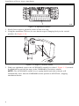
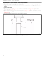
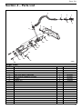
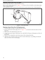
TM
COMPACT
Auger Installation, Operation
and Service Manual
Table of Contents
Section 1 – Installation of Power Auger Attachment ................................... 1–1
Operating Instructions for Power Auger Attachment .................................. 1–7
Removal of Hydraulically Powered Attachments...................................... 1–10
Removal of Power Auger Attachment ...................................................... 1–11
Removal of Power Auger from Drive Motor.............................................. 1–12
Section 2 – Parts List .................................................................................... 1–13
Section 3 – Troubleshooting ........................................................................ 1–14
Section 4 – Service and Maintenance ......................................................... 1–16
Daily Maintenance and Inspection..................................................... 1–16
Monthly Maintenance and Inspection ................................................ 1–16
Annual Maintenance and Inspection ................................................. 1–16
Hydraulic Drive Motor Replacement .................................................. 1–16
Planetary Auger Drive Gear Oil Check .............................................. 1–18
Planetary Auger Drive Gear Oil Replacement ................................... 1–18
Planetary Auger Drive Replacement ................................................. 1–19
i
ii
Section 1 – Installation of Power Auger Attachment
CAUTION
Before installing the Auger or any other powered attachment, be sure to refer to the
“Pre-Start Inspection” and “Machine Start-up” sections of the power units Operator's
Manual.
There are many hydraulically powered attachments available that are very easy to install. To
install any of these attachments:
1. Position the attachment on a level surface.
2. Start the machine engine, lower the loader arm and tilt the mounting plate forwards.
NOTE: Make sure that both of the attachment lock pins (Item 1, Figure 1–1) are in the
“unlocked” position.
1
1
Pins Unlocked
2021
Figure 1–1 Attachment Locks in Unlocked Position
3. Slowly drive towards the attachment and align the top edge of the male mounting plate
(Item 1, Figure 1–2) and the upper lip of the female attachment mounting plate (Item 2,
Figure 1–2).
1
Installation of Power Auger Attachment
4
1
3
2
2235
Figure 1–2 Hydraulically Powered Attachment Installed
NOTE: Make sure to position the attachments hydraulic hoses (Item 4, Figure 1–2) so that
they are not damaged during the installation process. Tuck the upper edge of the male
mounting plate into the upper lip of the female attachment mounting plate.
2
Installation of Power Auger Attachment
4. When the machines mounting plates top edge is seated in the attachment mounting plate,
curl the machines mounting plate backwards slightly to allow the lower edge of the
machines mounting plate to slide into position.
1
2236
Figure 1–3 Hydraulically Powered Attachment Installed
5. Shut the engine off.
6. Rotate the attachment lock pins (Item 1, Figure 1–3, and Item 1, Figure 1–4) into the locked
position securing the attachment to the machine.
1
1
2022
Figure 1–4 Attachment Locks in Locked Position
3
Installation of Power Auger Attachment
7. Start the engine and slowly tilt the attachment upwards and inspect to make sure that the
attachment lock pins are visible through the holes in the bottom of the attachment plate.
When the inspection has been completed, lower the auger assembly to the ground.
8. Shut off the engine.
9. Move any of the main hydraulic controls forward and backward to release any stored
hydraulic pressure.
10. Attach the hydraulic hoses to the quick connects. See Figure 1–5.
11. There are two hydraulic hoses that need to be connected. The quick connect system
prevents you from incorrectly connecting the hydraulic hoses, but both hoses need to be
connected for the attachment to operate.
a. With the engine OFF, move the AUXILIARY control lever (Item 1, Figure 1–5) toward
the hand hold, or the FORWARD position, or move the lever BACKWARD into the
REVERSE detent position. This will release the hydraulic pressure locked in the auxiliary hydraulic lines. Leave the control lever in the REVERSE detent position.
1
2
2074
Figure 1–5 Auxiliary Attachment Controls
4
Installation of Power Auger Attachment
b. Remove the protective covers (Items 2, 6, Figure 1–6) from the attachment quick connectors.
c. Wipe off the end of each of the connectors (Items, 3 and 5, Figure 1–6) to remove any
dirt or debris.
1
4
2
5
3
6
2024
Figure 1–6 Auxiliary Hydraulic Quick Connects
d. Insert the attachments' male coupling (Item 3, Figure 1–6) into the female bulkhead
quick connect coupling (Item 1, Figure 1–6) on the machine and push until the connector locks into position.
e. Repeat the above process to connect the attachments' female quick connect (Item 5,
Figure 1–6) on the other hose to the male bulkhead connector (Item 4, Figure 1–6) on
the machine.
f. Check the security of both connections by gently tugging on the attachment hoses to
make sure that the quick connects are seated properly.
5
Installation of Power Auger Attachment
12. Make sure that the hydraulic hoses are routed so that they will not be in the way or damaged
during machine operation. Figure 1–7 shows how the hoses might be routed to keep them
out of the way during operation and prevent them from being damaged.
2025
Figure 1–7 Attachment Hydraulic Hose Routing
13. The attachment is now ready to use.
CAUTION
Before starting the engine, make sure that the Auxiliary Hydraulic control lever is in the
NEUTRAL position. If this control is left in either the forward or reverse position and the
engine is started, the attachment will begin to function.
6
Installation of Power Auger Attachment
Operating Instructions for Power Auger Attachment
CAUTION
The instructions in this manual refer to a power unit that has an operator presence
control that when released, automatically shuts off the attachment, but allows the engine
to continue to operate. Other operator presence systems may have an electrical interface
designed into the operator's platform. This type of system will shut off the engine if the
operator leaves the control position. Make sure that you know which system is installed
on the power unit to which the accessory will be attached.
1. Move the engine throttle to the full speed setting and set “high-low” switch (Item 2,
Figure 1–8) to the High setting.
2. Raise the attachment off the ground and position it for use.
1
2
2074
Figure 1–8 Auxiliary Attachment Controls
CAUTION
• Have all buried lines such as; gas, electric, water, telephone and cable TV, marked
by the proper authorities.
• Make sure that you are standing on the operator's platform. (Item 1, Figure 1–9)
• DO NOT step off of the platform when the auxiliary attachment's power is
engaged.
• If you release the AUXILIARY hand control/operator presence control, the
attachment will automatically stop all motion.
7
Installation of Power Auger Attachment
1
2132
Figure 1–9 Operator's Platform
3. Slowly lower auger to ground at center of hole to be dug.
4. Using the attachment Tilt lever, be sure that the auger is hanging freely in the vertical
position, See Figure 1–10.
2207
Figure 1–10 Auger in Vertical Position
5. With your right hand, squeeze the AUXILIARY control lever (Item 1, Figure 1–11) towards
the hand hold to activate the auger in the FORWARD (Clockwise) motion.
NOTE: The AUXILIARY control lever is spring loaded and when released, will
automatically move from the FORWARD motion position to NEUTRAL, stopping
attachment motion.
8
Installation of Power Auger Attachment
1
2
2074
Figure 1–11 Auxiliary Attachment Controls
6. Using the Boom Raise & Lower Lever, slowly lower the auger to begin drilling. As needed,
lift auger out of hole. Move machine to a location away from hole & “shake” off excess dirt
using forward and reverse rotation of the auger.
NOTE: To reverse the operation of the attachment, move the auxiliary control lever (Item
1, Figure 1–11) to the REVERSE (toward front of machine) position. The control lever will
remain in the REVERSE position detent until it is moved to the NEUTRAL position.
7. When finished drilling, shut off the engine and de-pressurize hydraulic system by moving
the main hydraulic control forward and backward to release any stored hydraulic pressure.
9
Installation of Power Auger Attachment
Removal of Hydraulically Powered Attachments
CAUTION
After use, the quick couples and hydraulic fluid will be very hot. Wear gloves when
disconnecting the auxiliary hydraulic lines.
To remove a hydraulically powered attachment:
1. Return Auger assembly to storage rack on trailer and shut off the engine.
2. Move the auxiliary hydraulic control lever forward or backward to release any stored
hydraulic pressure.
3. Some of the female couplings will have a lock button preventing accidental disconnection.
To release this type of quick connect, rotate the collar on the female quick connect (Item 1,
Figure 1–12) to align the notch on the collar with the lock button (Item 2, Figure 1–12).
4. Slide the collar backwards on the female quick connect (Item 4, Figure 1–12) until it stops
against the lock button. The male connector will be released. Move the attachment hose
away from the bulkhead fitting.
5. If the female connector does not have the lock pin type collar, just slide the collar
backwards until the male connector is released.
5
3
2
1
4
2030
Figure 1–12 Quick Connect Locking Collar
6. Repeat this procedure on the other hydraulic line.
7. Cover the hose connections with the dust caps (Item 5, Figure 1–12) and store the hydraulic
hoses to prevent damage.
8. Follow the instructions in “Removal of Power Auger Attachment”.
10
Installation of Power Auger Attachment
Removal of Power Auger Attachment
1. Lower the attachment onto a firm, level surface.
2. Shut off the machine engine.
3. Rotate the attachment lock pins to the UNLOCKED position (Item 1, Figure 1–13).
5
3
2
1
4
2021
Figure 1–13 Attachment Locks in Unlocked Position
4. Start the engine and rotate the mounting plate downwards.
5. Back away from the attachment.
NOTE: It may be necessary to lower the loader arm assembly slightly to fully disengage
from the attachment.
11
Installation of Power Auger Attachment
Removal of Power Auger from Drive Motor
1. Lower the Auger into storage rack on the trailer.
2. Slightly raise or lower boom so the shaft is neither suspended nor bearing weight from the
boom.
3. Shut off the engine.
4. Remove nut (Item 4, Figure 1–14) and horizontal bolt (Item 3, Figure 1–14) from drive
shaft. (Item 1 Figure 1–14)
5. Raise boom to disengage drive motor shaft (Item 1, Figure 1–14) from Auger shaft. (Item 2,
Figure 1–14).
6. Reinstall bolt and nut onto drive motor shaft for storage.
2208
Figure 1–14 Auger Drive Shaft
12
Parts List
Section 2 – Parts List
4
3
2
6
7
9
1
5
11
10
8
12
13
14
15
16
10
19
20
18
17
2206
Auger Parts
Item No
1
2
3
4
5
6
7
8
9
10
11
12
13
14
15
16
17
18
19
20
Description
DUST CAP, FEMALE COUPLING
FEMALE QUICK CONNECT FITING
FITTING
HOSE ASSEMBLY
DUST CAP, MALE COUPLING
MALE QUICK CONNECT FITTING
FITTING
O-RING, #10
BOLT
FLAT WASHER
AUGER MOUNTING ARMS
BOLT
HYDRAULIC MOTOR
O-RING SEAL
NUT
PLANETARY AUGER DRIVE
NUT
AUGER MOUNTING WELDMENT
AUGER DRIVE SPACER
BOLT
Quantity
1
1
2
2
1
1
2
2
2
4
1
2
1
1
4
1
2
1
1
4
Part No.
2410354
2416626
2290143
3500132-065.92
2410353
2416627
2293502
2394885
1913390C
230149
3011045
1912940C
2391376
2297834
B045436
2414661
2294406
3011040
3011037
1913379C
13
Troubleshooting
Section 3 – Troubleshooting
WARNING
Hydraulic oil under pressure can penetrate body tissue causing serious injury and
possible death. When troubleshooting a hydraulic system for leaks, always use cardboard
or wood as a detector. DO NOT USE YOUR BARE HANDS. If you are injected with
hydraulic oil or any other fluids, immediately seek treatment by a doctor trained in the
treatment of penetrating fluid injuries.
Cause
Remedy
Auger does not turn
Problem
a. Auxiliary hydraulic lines not
connected.
b. Power unit has more that one
set of auxiliary hydraulic lines.
c. High/Low switch not in proper
setting.
d. Engine not at rated speed.
e. Auxiliary control lever not in the
proper position.
f. Power unit is low on hydraulic
fluid.
g. Auger drive motor is leaking
hydraulic fluid.
h. Planetary auger drive may
have failed.
Engine does not start with auger
attached.
a. Auxiliary control lever in activation position.
b. Operator not standing on operator platform.
c. Electric operator presence control system not functioning.
Auger rotates, but not smoothly or
stops and starts.
a. Soil may contain rocks or other
items that are preventing
smooth operation.
b. Power unit is low on hydraulic
fluid.
c. Auger hydraulic drive motor is
failing.
d. Planetary auger drive may
have failed.
a. Auxiliary hydraulic lines are
reversed.
a. Connect auxiliary hydraulic
lines.
b. Connect auger hydraulic lines
to the correct auxiliary hydraulic lines.
c. Set High/Low switch to the
High position.
d. Move throttle to maximum
RPM setting.
e. Hold Auxiliary control lever in
the activation position.
f. Refer to power units Operator's
Manual
g. Replace hydraulic auger drive
motor.
h. Separate hydraulic drive motor
from planetary auger drive.
Start power units engine and
activate the auger drive motor.
If the auger drive motors drive
shaft rotates, replace the planetary
a. Move control lever to Neutral
position.
b. Stand on operator platform at
all times when using auxiliary
attachments.
c. Refer to power units Operator's
Manual.
a. Raise auger from hole to clear
contact with the obstruction.
b. Refer to power units Operator's
Manual.
c. Replace hydraulic drive motor.
d. Replace planetary auger drive.
Auger rotates in reverse direction
when auxiliary control is activated.
14
a. Reverse hydraulic lines.
CAUTION - make sure to shut
off the engine and release
pressure in the hydraulic lines
before removing the hydraulic
lines from the quick connects.
a.
Troubleshooting
Problem
Hydraulic drive motor is turning
but the auger does not move
Hydraulic fluid is leaking from
auger drive motor.
Engine starts but does not continue to run when using auxiliary
attachment.
Poor auger performance, does not
penetrate soil easily.
Cause
Remedy
a. Auger connection bolt not
installed.
b. Planetary auger drive has
failed.
a. Hydraulic fitting loose.
b. Internal hydraulic motor seals
leaking.
a. Operator steps off operator
platform, operator presence
system shuts engine off.
b. Too much downward force is
being applied to attachment,
stalling engine.
c. Power unit low on fuel.
a. Worn outside teeth. The outside tooth on each auger blade
must be square.
a. Install and secure connection
bolt.
b. Replace planetary auger drive.
a. Tighten hydraulic fittings.
b. Replace hydraulic drive motor.
a. Remain on operator's platform
with using any auxiliary attachment.
b. Raise attachment slightly.
c. Refuel power unit.
a. Replace auger tooth
15
Service and Maintenance
Section 4 – Service and Maintenance
WARNING
Hydraulic oil under pressure can penetrate body tissue causing serious injury and
possible death. When troubleshooting a hydraulic system for leaks, always use cardboard
or wood as a detector. DO NOT USE YOUR BARE HANDS. If you are injected with
hydraulic oil or any other fluids, immediately seek treatment by a doctor trained in the
treatment of penetrating fluid injuries.
Daily Maintenance and Inspection
1. Inspect all hoses and connections for damage or wear. Replace any item that is showing
signs of damage.
2. Check outer auger teeth. Replace if the tooth is rounded off and not square.
Monthly Maintenance and Inspection
1. Check oil level in planetary auger drive. See Planetary Auger Drive Gear Oil Check and
Replacement later in this section.
Annual Maintenance and Inspection
1. Drain lubricant from auger drive.
a. Position auger drive over a container.
b. Remove drain plug and allow all fluid to drain out of auger drive.
Hydraulic Drive Motor Replacement
If the hydraulic drive motor has failed, it needs to be replaced. To replace the hydraulic motor:
1. Mark both hydraulic fittings, hoses, and hydraulic motor ports so that when the unit is reassembled the hydraulic lines are installed on the correct ports.
2. Remove both hydraulic lines (Item 1, Figure 1–15) from the hydraulic motor fittings.
3. Remove both 90° fittings (Item 2, Figure 1–15) and O-rings (Item 3, Figure 18) from the
hydraulic motor and set aside for reinstallation.
NOTE: Inspect the O-rings for signs of damage or wear. If any is noted, replace the
O-rings.
4. Remove the two hydraulic motor mounting bolts (Item 1, Figure 1–15).
16
Service and Maintenance
5. Remove the hydraulic motor (Item 5, Figure 1–15) from the top of the final gear drive (Item
7, Figure 1–15).
NOTE: Inspect the large O-ring (Item 6, Figure 1–15) for signs of wear or damage. If any
is noted, replace the O-ring.
6. Install new hydraulic drive motor by reversing steps 2 thru 5.
NOTE: When installing the O-ring seals, lubricate the O-ring using a small amount of
hydraulic fluid before reinstalling.
2209
Figure 1–15 Hydraulic Drive Motor Removal
17
Service and Maintenance
Planetary Auger Drive Gear Oil Check
Position auger assembly in a perpendicular position.
Remove the oil drain plug (Item 1, Figure 1–16). Proper oil level should be at the bottom edge
of the oil plug drain hole.
Add standard gear lube, SAE 80/130 until the level is at the bottom of the oil drain plug hole.
1
2211
Figure 1–16 Oil Drain Plugs
Planetary Auger Drive Gear Oil Replacement
1. Position auger assembly in a perpendicular position.
2. Remove the both oil drain plugs (Item 1, Figure 1–16), located on the front and rear of the
gear case.
3. Allow gear oil to drain from the gear case.
4. Using a gooseneck funnel, fill the gear case with SAE 80/130 gear oil through one of the oil
drain ports.
5. Proper oil level should be at the bottom edge of the oil plug drain hole.
6. When the gear oil begins to drip out of the second oil drain port, stop filling and reinstall
and secure both of the oil drain plugs.
18
Service and Maintenance
Planetary Auger Drive Replacement
If the planetary auger drive has failed, it needs to be replaced. To replace the auger drive:
1. Separate the hydraulic drive motor (Item 1, Figure 1–17) and O-ring (Item 2, Figure 1–17)
from the planetary auger drive (Item 4, Figure 1–17). See Hydraulic Motor Replacement
earlier in this manual.
2. Remove the four bolts (Item 7, Figure 1–17) and nuts (Item 3, Figure 1–17), releasing the
auger final drive from the auger mounting weldment (Item 5, Figure 1–17).
NOTE: The auger drive spacer (Item 6, Figure 1–17) will fall free. Keep this part for
reassembly.
3. Install new auger final drive by reversing steps 1 and 2 above.
2210
Figure 1–17 Replacing Auger Final Drive
19
Service and Maintenance
20
Compact Power Inc.
P.O. Box 40 – Fort Mill, SC 29716
Phone: 800-476-9673 – Fax: 803-548-2762
Web Site: http://www.cpiequipment.com/
Part Number XXX-XXX