1
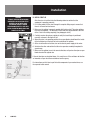
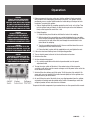
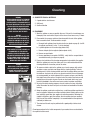
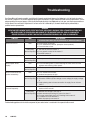
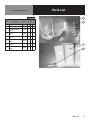
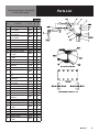
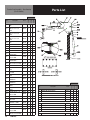
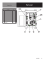
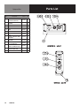
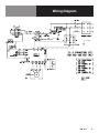
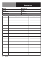
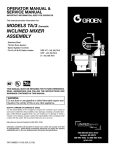
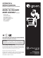
OPERATOR &
SERVICE MANUAL
IMPORTANT INFORMATION, KEEP FOR OPERATOR
This manual provides information for:
MODEL TA/3 INCLINED
MIXER ASSEMBLY Domestic
· Stainless Steel
· Tilt-Out Drive System
· Speed Agitator Controls
·
For 40, 60 & 80 Gallon Kettles:
DEE 4/T - (40, 60) TA/3
DHT - (40, 60) TA/3
D - (40, 60) TA/3
THIS MANUAL MUST BE RETAINED FOR FUTURE REFERENCE.
READ, UNDERSTAND AND FOLLOW THE INSTRUCTIONS AND
WARNINGS CONTAINED IN THIS MANUAL.
WARNING
Do not store or use gasoline or other flammable vapors
and liquids in the vicinity of this or any other appliance.
NOTIFY CARRIER OF DAMAGE AT ONCE
It is the responsibility of the consignee to inspect the container upon receipt of
same and to determine the possibility of any damage, including concealed damage. Unified Brands suggests that if you are suspicious of damage to make a
notation on the delivery receipt. It will be the responsibility of the consignee to file
a claim with the carrier. We recommend that you do so at once.
Manufacture Service/Questions 888-994-7636.
Information contained in this document is known to be current and accurate at the time
of printing/creation. Unified Brands recommends referencing our product line websites,
unifiedbrands.net, for the most updated product information and specifications.
PART NUMBER 141909, REV. C (03/15)
1055 Mendell Davis Drive
Jackson, MS 39272
888-994-7636, fax 888-864-7636
unifiedbrands.net
IMPORTANT - READ FIRST - IMPORTANT
CAUTION: BE SURE ALL OPERATORS READ, UNDERSTAND AND FOLLOW THE OPERATING INSTRUCTIONS,
CAUTIONS, AND SAFETY INSTRUCTIONS CONTAINED IN THIS MANUAL.
WARNING: THIS UNIT IS INTENDED FOR USE IN THE COMMERCIAL HEATING, COOKING AND HOLDING OF
WATER AND FOOD PRODUCTS, PER THE INSTRUCTIONS CONTAINED IN THIS MANUAL. ANY OTHER
USE COULD RESULT IN SERIOUS PERSONAL INJURY OR DAMAGE TO THE EQUIPMENT.
WARNING:
THE KETTLE MUST BE INSTALLED BY PERSONNEL QUALIFIED TO WORK WITH ELECTRICITY.
IMPROPER INSTALLATION CAN RESULT IN INJURY TO PERSONNEL AND/OR DAMAGE TO
EQUIPMENT.
DANGER:
ELECTRICALLY GROUND THE UNIT AT THE TERMINAL PROVIDED. FAILURE TO GROUND UNIT
COULD RESULT IN ELECTROCUTION AND DEATH.
WARNING:
AVOID ALL DIRECT CONTACT WITH HOT EQUIPMENT SURFACES. DIRECT SKIN CONTACT COULD
RESULT IN SEVERE BURNS.
WARNING: AVOID ALL DIRECT CONTACT WITH HOT FOOD OR WATER IN THE KETTLE. DIRECT CONTACT COULD
RESULT IN SEVERE BURNS.
CAUTION:
DO NOT OVER FILL THE KETTLE WHEN COOKING, HOLDING OR CLEANING. KEEP LIQUIDS A
MINIMUM OF 2-3” (5-8 CM) BELOW THE KETTLE BODY RIM TO ALLOW CLEARANCE FOR STIRRING,
BOILING AND SAFE PRODUCT TRANSFER.
WARNING:
TAKE SPECIAL CARE TO AVOID CONTACT WITH HOT KETTLE BODY OR HOT PRODUCT WHEN
ADDING INGREDIENTS, STIRRING OR TRANSFERRING PRODUCT TO ANOTHER CONTAINER.
WARNING:
DO NOT STAND ON OR APPLY UNNECESSARY WEIGHT OR PRESSURE ON THE KETTLE FRONT OR
POURING LIP. THIS COULD RESULT IN OVERLOAD AND FAILURE OF THE TILT MECHANISM, AND
POSSIBLE SERIOUS INJURY AND BURNS TO THE OPERATOR AND OTHERS.
WARNING: WHEN TILTING KETTLE FOR PRODUCT TRANSFER:
1) WEAR PROTECTIVE OVEN MITT AND PROTECTIVE APRON.
2) USE CONTAINER DEEP ENOUGH TO CONTAIN AND MINIMIZE PRODUCT SPLASHING.
3) PLACE CONTAINER ON STABLE, FLAT SURFACE, AS CLOSE TO KETTLE AS POSSIBLE.
4) STAND TO LEFT OR RIGHT SIDE OF KETTLE WHILE POURING. DO NOT STAND DIRECTLY IN
POUR PATH OF HOT CONTENTS.
5) POUR SLOWLY, MAINTAIN CONTROL OF KETTLE, AND RETURN KETTLE BODY TO UPRIGHT
POSITION AFTER CONTAINER IS FILLED OR TRANSFER IS COMPLETE.
6) DO NOT OVER-FILL CONTAINER. AVOID DIRECT SKIN CONTACT WITH HOT CONTAINER AND ITS
CONTENTS.
CAUTION: KEEP FLOORS IN FRONT OF KETTLE WORK AREA CLEAN AND DRY. IF SPILLS OCCUR, CLEAN
IMMEDIATELY, TO AVOID SLIPS OR FALLS.
WARNING: FAILURE TO CHECK PRESSURE RELIEF VALVE OPERATION PERIODICALLY COULD RESULT IN
PERSONAL INJURY AND/OR DAMAGE TO EQUIPMENT.
WARNING: WHEN TESTING, AVOID ANY EXPOSURE TO THE STEAM BLOWING OUT OF THE PRESSURE RELIEF
VALVE. DIRECT CONTACT COULD RESULT IN SEVERE BURNS.
WARNING: TO AVOID INJURY, READ AND FOLLOW ALL PRECAUTIONS STATED ON THE LABEL OF THE WATER
TREATMENT COMPOUND.
WARNING: BEFORE REPLACING ANY PARTS, DISCONNECT THE UNIT FROM THE ELECTRIC POWER SUPPLY.
WARNING: TURN OFF POWER AT THE CIRCUIT BREAKER PRIOR TO INSTALLATION OR SERVICE.
2OM-TA/3
IMPORTANT - READ FIRST - IMPORTANT
WARNING: THE MIXER MUST BE INSTALLED BY PERSONNEL WHO ARE QUALIFIED TO WORK WITH
ELECTRICITY, IMPROPER INSTALLATION CAN RESULT IN INJURY TO PERSONNEL AND/OR DAMAGE
TO EQUIPMENT.
WARNING: ANY MECHANICAL OR ELECTRICAL CHANGE MUST BE APPROVED BY THE GROEN FOOD SERVICE
ENGINEERING DEPARTMENT.
WARNING: TURN OFF AGITATOR BEFORE ADDING INGREDIENTS OR INSPECTING KETTLE CONTENTS. DO NOT
WEAR LOOSE CLOTHING OR JEWELRY AROUND OPERATING MIXER KETTLE. KEEP WELL CLEAR OF
ROTATING MIXER ARMS AND PADDLES AT ALL TIMES.
WARNING: THE UNIT IS EQUIPPED WITH AN AUTOMATIC CUTOFF SWITCH. IF POWER IS ON WHEN A TILTED
MIXER IS LOWERED INTO THE OPERATING POSITION, THE MIXER WILL AUTOMATICALLY START.
CAUTION: STARTING WITH THE MIXER SET AT HIGH SPEED MAY CAUSE MATERIAL TO SPILL OUT OF THE
KETTLE ON TWO SPEED AND VARIABLE SPEED UNITS.
CAUTION: UNDER HEAVY LOAD DO NOT RUN THE MIXER CONTINUOUSLY AT SLOWER THAN 5% OF FULL
SPEED. SLOWER OPERATION COULD DAMAGE THE SPEED CONTROL.
WARNING: BEFORE CLEANING ANY PART OF THE MIXER, OTHER THAN THE AGITATOR, DISCONNECT THE
ELECTRICAL SUPPLY AT THE CIRCUIT BREAKER OR FUSE BOX TO AVOID POSSIBLE ELECTRICAL
SHOCK.
WARNING: KEEP WATER AND SOLUTIONS OUT OF THE CONTROLS, ELECTRICAL WIRING, AND DRIVE
MECHANISM. NEVER SPRAY OR HOSE THE MIXER.
CAUTION: WHEN YOU INSTALL THE SCRAPER BLADES, MAKE SURE THE SCRAPER IS CURVED. A REVERSED
SCRAPER WILL NOT SCRAPE AND CAN CAUSE SERIOUS DAMAGE.
WARNING: AVOID CONTACT WITH CLEANING PRODUCTS IN ACCORDANCE WITH SUPPLIER AND
MANUFACTURER RECOMMENDATIONS. MANY CLEANERS ARE HARMFUL TO THE SKIN, EYES,
MUCOUS MEMBRANES AND CLOTHING. READ THE WARNINGS AND FOLLOW DIRECTIONS ON THE
CLEANER LABEL.
WARNING: USE OF ANY REPLACEMENT PARTS OTHER THAN THOSE SUPPLIED BY GROEN OR THEIR
AUTHORIZED DISTRIBUTOR VOIDS ALL WARRANTIES AND CAN CAUSE BODILY INJURY TO THE
OPERATOR AND DAMAGE TO THE EQUIPMENT.
WARNING: SERVICE PERFORMED BY OTHER THAN FACTORY AUTHORIZED PERSONNEL WILL VOID ALL
WARRANTIES.
WARNING: BEFORE REPLACING ANY PARTS, SHUT OFF ALL ELECTRIC POWER SUPPLIES TO THE COOKER/
MIXER.
WARNING: USE ONLY GROEN-SUPPLIED PARTS. SUBSTITUTION OF UNAUTHORIZED OR GENERIC PARTS CAN
RESULT IN BODILY INJURY TO THE OPERATOR AND DAMAGE TO THE EQUIPMENT.
WARNING:
DO NOT PLACE HANDS, TOOLS, OR HOSES IN KETTLE WHILE AGITATOR IS MOVING.
WARNING:
AGITATOR AREA MUST BE CLEAR OF OBSTRUCTION BEFORE OPERATION. TO RUN AGITATOR:
1) ENSURE KETTLE IS FULLY UPRIGHT
2) ENSURE MIXER HEAD IS FULLY DOWN AND LATCHED
3) SET THE SPEED DIAL TO DESIRED SPEED
4) TURN THE START SWITCH TO ON
TO STOP AGITATOR:
1) PRESS THE RED STOP BUTTON OR TURN THE SWITCH TO OFF
OM-TA/3
3
Table of Contents
Important Operator Warnings ....................................................page 2-3
References.................................................................................... page 4
Equipment Description.................................................................. page 5
Installation .................................................................................. page 5-6
Operation ...................................................................................... page 7
Cleaning ....................................................................................... page 8
Maintenance................................................................................. page 9
Troubleshooting............................................................................ page 10
Parts Lists .............................................................................. page 11-16
Wiring Diagram ............................................................................ page 17
Service Log .................................................................................. page 18
References
NATIONAL FIRE PROTECTION ASSOCIATION
60 Battery March Park
Quincy, Massachusetts 02269
NFPA/70 The National Electrical Code
4OM-TA/3
Equipment Description
The Groen TA/3 assembly is an electrically powered mixer with dual counter rotating
agitators, which is incorporated into Groen kettles of 40 to 80 gallon capacity. The
main agitator is anchor type and of tubular stainless steel and fitted with scraper
fingers. Both the scraper fingers and the agitator assembly are easily removed.
The secondary, counter rotating agitator is constructed of stainless steel and is easily
removeable. The mixer has a variable speed drive with electrical speed control.
For a description of the kettle component of your cooker/mixer, see the separate kettle
manual.
Installation
WARNING
TURN OFF POWER AT THE CIRCUIT
BREAKER PRIOR TO INSTALLATION.
THE MIXER MUST BE INSTALLED BY
PERSONNEL WHO ARE QUALIFIED TO
WORK WITH ELECTRICITY. IMPROPER
INSTALLATION CAN RESULT IN INJURY TO
PERSONNEL AND/OR DAMAGE TO
EQUIPMENT.
ANY MECHANICAL OR ELECTRICAL
CHANGE MUST BE APPROVED BY THE
GROEN FOOD SERVICE ENGINEERING
DEPARTMENT.
WARNING
TO PREVENT POSSIBLE ELECTRIC SHOCK,
GROUND THE UNIT AT THE TERMINAL
PROVIDED.
Your Groen mixer has been test operated at the factory and is furnished with all
internal wiring. It is complete and ready for final connection. A wiring diagram is
furnished at the rear of this manual.
A. INSTALLATION
1. Set the cooker/mixer in place and level it. If the mixer is a tilting model, confirm
that there is enough rear or side clearance, depending on model, and overhead
clearance to tilt the mixer safely through its entire tilting range. Provide enough
clearance to permit access for service as well. Cooker/Mixers are provided with
flanged feet and/or mounting plates.
2. Provide the proper electric power supply as specified on the electrical information
plate attached to the mixer. Observe local codes and/or The National Electrical
Code in accordance with ANSI/NFPA 70 - latest edition. The installation must
conform to the code that has the more strict requirements.
3. Your mixer requires a permanent connection with the electrical service. Use
waterproof conduit and waterproof connectors for this connection. Install the
conduit fittings on the side or bottom of the equipment box, not on the top.
4. Any electrical service for the kettle will require a separate connection. See the
specific kettle manual.
5. Use the following check list to confirm that the installation is correct.
¨ Unit level (reference to kettle rim)
¨ Adequate clearance for tilting
¨ Access for service
¨ Unit fastened down
¨ Mixer power supply conforms to information plate and code
¨ Electrical conduit and connections are waterproof
¨ Mixer grounded
For instructions on installing the kettle component of your cooker/mixer, see the
separate kettle manual.
OM-TA/3
5
Installation
WARNING
TURN OFF AGITATOR BEFORE ADDING
INGREDIENTS OR INSPECTING KETTLE
CONTENTS. DO NOT WEAR LOOSE
CLOTHING OR JEWELRY AROUND
OPERATING MIXER KETTLE. KEEP WELL
CLEAR OF ROTATING MIXER ARMS AND
PADDLES AT ALL TIMES.
Slip-on Coupling
B. INITIAL START-UP
After the mixer is installed, take the following actions to confirm that the
equipment is operating correctly.
1. For a tilting model, tilt the mixer through its complete tilting range to ensure that
there is no hazard or interference.
2. Make sure the agitator is properly coupled with its drive shaft. The mixer agitators
have slip-on couplings. The drive pin of each shaft must be positioned at the end
of the J-slot in the mating coupling. (See photograph at left)
3. Carefully examine the primary agitator to verify that each finger is positioned
correctly as shown in the figure at left.
4. When the mixer is in operating position, the scraper blades should touch the inside
of the kettle during at least part of each revolution of the agitator.
5. At the circuit breaker or fuse box, turn on the electric power supply to the mixer.
6. Switch on the drive and confirm that the mixer operates smoothly throughout its
speed range.
7. Make sure the agitator turns in the correct direction, so it pushes the nylon scraper
blades ahead of the agitator bar.
If the unit functions as described above, it is ready for use. If the unit does not function
as intended, call your local Groen authorized service agency.
For instructions on initial start-up of the kettle component of your cooker/mixer, see
the separate kettle manual.
6OM-TA/3
Operation
WARNING
TURN OFF AGITATOR BEFORE ADDING
INGREDIENTS OR INSPECTING KETTLE
CONTENTS. DO NOT WEAR LOOSE CLOTHING
OR JEWELRY AROUND OPERATING MIXER
KETTLE. KEEP WELL CLEAR OF ROTATING
MIXER ARMS AND PADDLES AT ALL TIMES.
WARNING
THE UNIT IS EQUIPPED WITH AN
AUTOMATIC TILT CUTOFF SWITCH. IF
POWER IS ON WHEN A TILTED MIXER IS
LOWERED INTO OPERATING POSITION,
THE MIXER WILL AUTOMATICALLY START.
CAUTION
STARTING WITH THE MIXER SET AT HIGH
SPEED MAY CAUSE MATERIAL TO SPILL OUT
OF THE KETTLE ON VARIABLE SPEED UNITS.
CAUTION
UNDER HEAVY LOAD DO NOT RUN THE
MIXER CONTINUOUSLY AT SLOWER THAN
5% OF FULL SPEED. SLOWER OPERATION
COULD DAMAGE THE SPEED CONTROL.
1. Before you operate the mixer, make sure that the agitator is firmly connected
with the drive shaft and properly positioned in the kettle. The agitator must be
positioned so every scraper blade touches the kettle during at least part of each
revolution. To connect the agitator:
a. Slip-on Coupling: Slide the coupling up onto the shaft as far as it will go. Then
turn the agitator and pull it down, so that the drive pin on the shaft becomes
firmly seated against the end of the J-slot.
b. Bolted Coupling:
1. Guide the two pins of the drive shaft into the holes in the coupling.
2. With the lobe of the cam pointing up, and while holding the two cam bolts,
insert the bolts through the larger holes in the side of the coupling. The bolts
must pass the flat part of the shaft, and through the smaller holes in the
other side of the coupling.
3. Turn the cam bolts toward the shaft 1/8 turn or until the lobe of the cam is
snug against the flat side of the shaft.
4. Fasten the bolts in place with the supplied hex nuts, and tighten the nuts.
2. If the mixer has been tilted up, lower it into operating position.
3. Turn on electric power to the unit at the circuit breaker or fuse box.
4. Switch on the drive.
5. Set the desired mixing speed.
a. On a variable speed drive with electrical speed control, turn the speed
adjustment knob.
6. To stop the mixer, switch off the drive. If the cooker/mixer will be cleaned or
serviced, or will not be used for a week or longer, cut off all power to the unit at the
circuit breaker or fuse box.
7. Switch off the drive, before you tilt the mixer. To tilt the mixer, first unlatch it. For
some units, you may need to tilt the kettle forward slightly to let the agitator clear
the kettle wall as you tilt the mixer.
8. As you tilt the mixer out of the kettle, clean any clinging product from the agitator,
so product will not drip onto the outside of the kettle or surroundings, and so the
weight of product will not make the mixer fall down.
To operate the kettle component of your cooker/mixer, see the separate kettle manual.
OM-TA/3
7
Cleaning
WARNING
BEFORE CLEANING ANY PART OF THE MIXER,
OTHER THAN THE AGITATOR, SHUT OFF ALL
ELECTRIC POWER TO THE COOKER/MIXER AT
THE CIRCUIT BREAKER OR FUSE BOX, TO AVOID
POSSIBLE ELECTRIC SHOCK. KEEP WATER
AND SOLUTIONS OUT OF THE CONTROLS,
ELECTRICAL WIRING, AND DRIVE MECHANISM.
NEVER SPRAY OR HOSE THE MIXER.
CAUTION
WHEN YOU CONNECT THE SCRAPER WITH
THE YOKE, MAKE SURE THE SCRAPER IS
CURVED THE SAME WAY AS THE KETTLE.
A REVERSED SCRAPER WILL NOT SCRAPE
AND CAN CAUSE SERIOUS DAMAGE.
WARNING
AVOID CONTACT WITH ANY CLEANER, AS
RECOMMENDED BY THE SUPPLIER.
CAREFULLY READ THE WARNINGS AND
FOLLOW THE DIRECTIONS ON THE LABEL
OF THE CLEANER. MANY CLEANERS ARE
HARMFUL TO THE SKIN, EYES, MUCOUS
MEMBRANES, AND CLOTHING.
CAUTION
NEVER LEAVE A SANITIZER IN CONTACT
WITH THE SURFACE OF STAINLESS STEEL
LONGER THAN 20 MINUTES. LONGER
CONTACT CAN CAUSE CORROSION.
A. SUGGESTED TOOLS & MATERIALS
1. A good stainless steel cleaner.
2. Stiff brush.
3. Sanitizer Solution
B. PROCEDURE
1. Wash the agitator as soon as possible after use. If the unit is in continuous use,
thoroughly clean and sanitize all parts of the mixer at least once every 12 hours
2. Disassemble the scrapers and clean them along with the rest of the agitator,
then reassemble them. To disassemble a scraper:
a. Decouple both agitators from the drive shafts (see photo on page 6). Just lift
the agitator and rotate it in the “J” slot to decouple.
b. Lay both agitators on flat surface (top photo at left)
c. Remove hairpin clip from agitator (bottom photo at left)
d. Remove scraper blades.
e. Reverse procedure to assemble. CAUTION - verify that the scraper blade is
assembled correctly (see figure on page 6).
3. Prepare a hot solution of the cleaning compound as instructed by the supplier.
Wash the agitator parts and rinse them well. Use a cloth moistened with the
cleaning solution to clean other parts of the mixer.
4. To remove materials stuck to the agitator, use a brush, sponge, cloth, plastic
or rubber scraper, or plastic wool along with the cleaning solution. To make
washing easier, let the cleaning solution soak into the residue. When you clean
the stainless steel parts, do not use any abrasive material (like metal sponges
or scouring powder) or metal implement (like a spoon, scraper, or wire brush)
that might scratch the surface. Scratches make the surface hard to clean and
provide places for bacteria to grow. Do not use steel wool, which may leave
particles imbedded in the surface and cause eventual corrosion and pitting.
5. As part of the daily cleaning program, clean all surfaces that may have been
soiled. Remember to check such parts as the back and underside of the drive
housing.
6. When the agitator needs to be sanitized, use a sanitizing solution equivalent to
one that supplies 100 parts per million available chlorine. Obtain advice on the
best sanitizing agent from your supplier of sanitation products. Following the
supplier’s directions, apply the sanitizer after the agitator has been washed,
then rinse off the sanitizer completely. It is recommended that the agitator be
sanitized just before use.
7. The exterior of the unit may be polished with a good quality stainless steel
cleaner.
Cleaning procedures for the kettle component of your cooker/mixer are described in
the separate kettle manual.
8OM-TA/3
Maintenance
WARNING
USE OF ANY REPLACEMENT PARTS
OTHER THAN THOSE SUPPLIED BY GROEN
OR THEIR AUTHORIZED DISTRIBUTOR
VOIDS ALL WARRANTIES AND CAN CAUSE
BODILY INJURY TO THE OPERATOR AND
DAMAGE TO THE EQUIPMENT.
SERVICE PERFORMED BY OTHER THAN
FACTORY AUTHORIZED PERSONNEL WILL
VOID ALL WARRANTIES.
WARNING
BEFORE REPLACING ANY PARTS, SHUT
OFF ALL ELECTRIC POWER SUPPLIES TO
THE COOKER/MIXER.
A. PERIODIC SERVICE
1. The interior of control and drive housings should be kept clean and dry.
2. Electrical wiring should be kept securely connected and in good condition.
3. Regular service of the mixer should include cleaning the motor and checking the
reducer gearcase. Check oil level at 3000 hours of operation or every 6 months.
Change oil completely every 3 years or every 15,000 hours. Lubricant type is GG
Artic SHC 23” Food grade lubricant (Mobil product).
4. Every six (6) months lubricate all grease fittings on the transfer case with a USDA
approved food grade grease/lubricant. Wipe off excess lubricant.
B. COMPONENT REPLACEMENT
All internal wiring is marked as shown on the schematic drawings in this manual. Be
sure that new components are wired in the same manner as the old components.
C. SERVICE RECORDS
A Service Log is provided At the rear of this manual. Each time service is performed
on this equipment, enter the date on which the work was done, what was done, and
who did it. Keep this log with the equipment.
Service procedures for the kettle component of the cooker/mixer are described in the
separate kettle manual.
OM-TA/3
9
Troubleshooting
Your Groen Mixer will operate smoothly and efficiently if properly maintained. However, the following is a list of checks to make in
the event of a problem. If the actions suggested do not solve the problem, call your authorized Groen Service Representative. For the
phone number of the nearest agency, check the Unified Brands web site at unifiedbrands.net, ask your area Groen representative or
call the Groen Parts and Service Department. If an item on the list is followed by X, the work should only be performed by a
qualified service representative.
WARNING
USE OF ANY REPLACEMENT PARTS OTHER THAN THOSE SUPPLIED BY GROEN OR THEIR AUTHORIZED DISTRIBUTORS
CAN CAUSE INJURY TO THE OPERATOR AND DAMAGE TO THE EQUIPMENT AND WILL VOID ALL WARRANTIES.
SERVICE PERFORMED BY OTHER THAN FACTORY-AUTHORIZED PERSONNEL WILL VOID ALL WARRANTIES.
SYMPTOM
WHO
Motor will not run.
User
WHAT TO CHECK
X indicates items which must be performed by an authorized technician.
a. Power supply to the unit.
b. For a mechanical overload. (example: frozen product)
c. Circuit breaker or fuse.
Authorized
d. That the tilt switch is closed. X
Service Rep Only e. For a ground or short in the motor. X
f. Overload heaters. X
Motor runs slowly.
User
a. For a mechanical overload.
Authorized
b. For open motor field circuit, by checking field current. X
Service Rep Only
Motor speed varies
rapidly.
User
a. For an oscillating load, by disconnecting the mixer drive from the
agitator and checking motor speed.
Authorized
b. Variable speed controller X
Service Rep Only
Motor overheats and/or
sparks excessively.
User
a. For a mechanical overload.
b. Ambient temperature is high.
Authorized
c. Incorrect supply voltage to motor. X
Service Rep Only d. Excessive variation (under voltage or over voltage) in supply voltage.
X
e. Single phasing due to loose connection in supply line or a blown
fuse. X
Circuit breaker or heater
cuts out frequently.
User
a. For air in the jacket. See “Jacket Vacuum” in the “Maintenance”
section of this manual.
Authorized
b. Whether line voltage is too high. X
Service Rep Only c. Motor armature and wiring for ground or short. X
d. For open motor field circuit, by checking field current. X
e. For defective circuit breaker. X
f. Motor improperly connected. X
Troubleshooting guidance for the kettle component of your cooker/mixer is contained in the separate kettle manual.
10OM-TA/3
Parts List
Twin-Agitator Components
40 Gal
60 Gal
80 Gal
QUANTITY
A
FINGER, SCRAPER
006502
14
16
18
B
PIN, CIRCULAR, COTTER
111957
2
2
2
C
AGITATOR, PRIMARY,
40 GAL
009243
1
-
-
D
AGITATOR, SECONDARY,
40 GAL
009686
1
-
-
C
AGITATOR, PRIMARY,
60 GAL
009244
-
1
-
D
AGITATOR, SECONDARY,
60 GAL
009687
-
1
-
C
AGITATOR, PRIMARY,
80 GAL
009245
-
-
1
D
AGITATOR, SECONDARY,
80 GAL
009688
-
-
1
Ref
Description
Part #
C
D
A
B
OM-TA/3
11
Parts List
Transfer Case Assembly – Front Housing
Ref
Description
Part #
40 Gal
60 Gal
80 Gal
QUANTITY
1
FRONT HOUSING, TRANSFER
CASE
009263
1
-
-
1
FRONT HOUSING, TRANSFER
CASE
009250
-
1
1
2
GEAR, PINION (24 TEETH)
009268
1
-
-
2
GEAR, PINION (28 TEETH)
009254
-
1
-
2
GEAR, PINION (32 TEETH)
009255
-
-
1
3
MOUNTING PLATE,
GEARMOTOR
135118
1
-
-
4
PIN, COUPLING, 3/8" DIA X
7/8" LONG
009253
1
1
1
5
SET COLLAR, 1" ID
012012
1
1
1
6
SCREW, MACHINE, HEX
HEAD, 1/4-20 X 1" LONG
005610
4
8
8
7
WASHER, LOCK, 1/4"
005655
4
8
8
8
KEY, 1/4 X 1/4 X 1-1/2"
009249
1
1
1
9
SHAFT, MOTOR DRIVE
135117
1
-
-
9
SHAFT, MOTOR DRIVE
132026
-
1
1
10
SCREW, MACHINE, HEX HEAD,
7/16-14 X 1-1/2" LONG
006029
1
-
-
11
SCREW, MACHINE, SOCKET
CAP, 5/16-18 X 1-1/2" LONG
115302
4
-
-
12
WASHER, LOCK, 5/16
005656
4
-
-
13
RING, EXTERNAL
009223
2
2
2
14
BEARING, CYLINDRICAL
009209
3
3
3
15
HOUSING, ECCENTRIC
009204
1
1
1
16
FITTING, GREASE, STRAIGHT
012100
3
3
3
17
SEAL, SHAFT
001758
2
2
2
18
WASHER, LOCK, 5/16
005656
12
12
12
19
SCREW, MACHINE, HEX
HEAD, 5/16-18 X 1" LONG
005613
12
12
12
20
HOUSING, TOP BEARING
009205
1
1
1
21
COVER PLATE
128379
1
1
1
22
SCREW, ROUND HEAD, #1032 X 3/8" LONG
006009
4
4
4
23
GEAR, SPUR (64 TEETH)
009269
1
-
-
23
GEAR, SPUR (72 TEETH)
009260
-
1
-
23
GEAR, SPUR (80 TEETH)
009261
-
-
1
24
WASHER, THRUST, 1"
009208
1
1
1
25
HOUSING, FRONT BEARING
009203
1
1
1
26
KEY, 1/4 X 1/4 X 2"
009258
1
1
1
27
SHAFT, 1" DIA X 11-1/2"
LONG
009557
1
1
1
28
PIN, COUPLING, 1/2" DIA X
1-3/4" LONG
009305
1
1
1
12OM-TA/3
Parts List
Transfer Case Assembly – Rear Housing
(For DHT & DEE/4 Kettles)
Ref
Description
Part #
40 Gal
60 Gal
QUANTITY
29
REAR HOUSING, TRANSFER CASE
SCREW, MACHINE, HEX HEAD, 1/213 X 1-1/4" LONG
SCREW, MACHINE, HEX HEAD, 1/213 X 2-1/4" LONG
SCREW, MACHINE, HEX HEAD, 1/213 X 1-3/4" LONG
NUT, HEX, 1/2-13 HEAVY DUTY
WASHER, LOCK, 1/2
POWER-AID ASSEMBLY
POWER-AID ASSEMBLY
HANDLE AND LATCH ASSEMBLY
HANDLE AND LATCH ASSEMBLY
SCREW, MACHINE, HEX HEAD, 5/16
X 3/4" LONG
SCREW, MACHINE, HEX HEAD, 5/16
X 1" LONG
WASHER, LOCK, 5/16
PIN, POWER-AID, TOP CONNECTION
PIN, POWER-AID, BOTTOM
CONNECTION
RING, RETAINING, EXTERNAL
COVER PLATE, TOP, REAR TRANSFER
CASE
SCREW, FLAT HEAD, #3/8-16 X 3/4"
LONG
COVER PLATE, BACK, REAR
TRANSFER CASE
SCREW, MACHINE, HEX HEAD, 1/420 X 5/8" LONG
WASHER, LOCK, 1/4"
GASKET, 5/32 X 1/2 X 8" LONG
GASKET, 5/32 X 1/2 X 10-1/8" LONG
SHAFT, 3/4" DIA X 7-5/8" LONG
COVER, TRUNNION, AGITATOR TILT
COVER, INSIDE, TRUNNION,
AGITATOR TILT
WASHER, COVER PLATE GASKET
SEAL, COVER PLATE GASKET
BEARING, ROLLER, 1" ID
SCREW, ROUND HEAD, #10-24 X
3/8" LONG
BASE, PIVOT
BASE, PIVOT
SWITCH, TILT
BRACKET, TILT SWITCH
SCREW, ROUND HEAD, #8-32 X
5/8" LONG
009295
1
1
005623
5
5
005728
2
2
005734
3
3
005705
005735
009718
009719
044392
041015
5
10
1
1
-
5
10
1
1
006014
4
-
005613
-
4
005656
012899
4
2
4
2
012890
2
2
001538
4
4
009608
1
1
013466
2
2
132037
1
1
078546
12
12
005655
005233
002121
009694
006972
12
1
2
1
2
12
1
2
1
2
006973
2
2
006974
006975
009212
2
2
2
2
2
2
006009
6
6
128618
003662
122176
128408
1
1
1
1
1
1
007526
1
1
30
31
32
33
34
35
35
36
36
37
38
39
40
41
42
43
44
45
46
46a
47
48
49
50
51
52
53
54
55
56
56
57
58
59
OM-TA/3
13
Parts List
Transfer Case Assembly – Rear Housing
(For DL Kettles)
60 Gal
80 Gal
60
REAR HOUSING, TRANSFER
CASE
SCREW, MACHINE, HEX
HEAD, 1/2-13 X 1-1/4"
LONG
SCREW, MACHINE, HEX
HEAD, 1/2-13 X 2-1/4"
LONG
SCREW, MACHINE, HEX
HEAD, 1/2-13 X 1-3/4"
LONG
NUT, HEX, 1/2-13 HEAVY
DUTY
WASHER, LOCK, 1/2
POWER-AID ASSEMBLY
POWER-AID ASSEMBLY
POWER-AID ASSEMBLY
COVER PLATE, TOP, REAR
TRANSFER CASE
SCREW, FLAT HEAD, #3/816 X 3/4" LONG
COVER PLATE, BACK, REAR
TRANSFER CASE
SCREW, MACHINE, HEX
HEAD, 1/4-20 X 5/8" LONG
WASHER, LOCK, 1/4"
GASKET, 5/32 X 1/2 X 8"
LONG
GASKET, 5/32 X 1/2 X 101/8" LONG
SHAFT, 3/4" DIA X 7-5/8"
LONG
COVER, TRUNNION,
AGITATOR TILT
COVER, INSIDE, TRUNNION,
AGITATOR TILT
WASHER, COVER PLATE
GASKET
SEAL, COVER PLATE
GASKET
BEARING, ROLLER, 1" ID
SCREW, ROUND HEAD, #1024 X 3/8" LONG
PIN, CONNECTING, POWER-AID
WASHER, PLAIN, 1/2" ID,
0.078" THICK
PIN, COTTER, 1/8"
DIAMETER X 1" LONG
SWITCH, TILT
BRACKET, TILT SWITCH
SCREW, ROUND HEAD, #832 X 5/8" LONG
SCREW, MACHINE, HEX
HEAD, 5/8-11 X 3/4" LONG
009295
1
1
1
005623
5
5
5
005728
2
2
2
005734
3
3
3
005705
5
5
5
005735
009677
012903
009642
10
1
-
10
1
-
10
1
132037
1
1
1
013466
2
2
2
013873
1
1
1
078546
12
12
12
005655
12
12
12
005233
1
1
1
002121
2
2
2
009694
1
1
1
006972
2
2
2
006973
2
2
2
006974
2
2
2
006975
2
2
2
009212
2
2
2
006009
6
6
6
013405
2
2
2
005598
4
4
4
009246
4
4
4
122176
128408
1
1
1
1
1
1
007526
1
1
1
009878
2
2
2
61
62
63
64
65
66
66
66
67
68
69
70
71
72
73
74
75
76
77
78
79
80
81
82
83
84
85
86
87
14OM-TA/3
QUANTITY
Ref
Description
88 HANDLE AND LATCH ASSEMBLY
88 HANDLE AND LATCH ASSEMBLY
88 HANDLE AND LATCH ASSEMBLY
89 SCREW, MACHINE, HEX HEAD, 5/16 X 3/4" LONG
90 SCREW, MACHINE, HEX HEAD, 5/16 X 1" LONG
91 WASHER, LOCK, 5/16
MOTOR AND DRIVE GEAR
MOTOR & DRIVE GEAR ASM, 1.5HP, 208V/360V
MOTOR & DRIVE GEAR ASM, 2.0HP, 208V/360V
MOTOR & DRIVE GEAR ASM, 1.5HP, 240V/480V
MOTOR & DRIVE GEAR ASM, 2.0HP, 240V/480V
HARDWARE
KNOB, BALL, RED
Part #
80 Gal
Part #
60 Gal
Description
40 Gal
Ref
40 Gal
QUANTITY
044392
041015
026685
006014
005613
005656
1
4
4
1
4
4
1
4
4
135822
132099
135578
128979
1
1
-
1
1
1
1
012691
1
1
1
Parts List
Equipment Box
Ref
1
2
3
4
4
5
6
7
8
9
10
Description
CONTACTOR, 12A, 4-POLE
BLOCK, FUSE, 2-POLE
FUSE, 20A, CLASS CC
INVERTER, 2HP, 200/240V
INVERTER 2 HP, 380/460V
LUG, GROUND, 14-16 AWG
SOCKET, RELAY
RELAY, CONTROL
BLOCK, TERMINAL, 3-POLE
TRANSFORMER, 100VA
WIRING KIT, VAR. SPEED
PLATE, CONTACTOR
MOUNTING
Part #
Qty
111072
096809
071489
120436
128975
119829
115359
115358
003888
115356
132383
1
1
2
1
1
1
1
1
1
1
1
128384
1
OM-TA/3
15
Parts List
Equipment Box
Ref
Description
Part #
Qty
-
ASSY, ELECTRICAL CONTROL,
OPERATOR (COMPLETE)
SWITCH, START-STOP,
AGITATOR
SWITCH, SPEED, AGITATOR
SWITCH, EMERGENCY STOP
LEGEND PLATE, START STOP
LEGEND PLATE, BLANK
LEGEND PLATE, EMERGENCY
STOP
BRACKET, CONTROL, HORIZ.
MOUNTING
BRACKET, CONTROL, VERT.
MOUNTING
WIRING HARNESS, CONTROL
ASSY TO EQMT BOX
WIRING HARNESS, TILT
SWITCH TO CONTROL ASSY
WIRING HARNESS, AGITATOR
MOTOR TO EQMT BOX
WIRING DIAGRAM
128458
1
128485
1
115341
115342
1
1
128477
1
128478
1
128479
1
128386
1
128490
1
128482
1
128483
1
128484
1
128491
1
11
12
13
14
15
16
17
18
-
16OM-TA/3
Wiring Diagram
OM-TA/3
17
Service Log
Model No:
Purchased From:
Serial No:
Location:
Date Purchased:
Date Installed:
Purchase Order No:
For Service Call:
Date
18OM-TA/3
Maintenance Performed
Performed By
1055 Mendell Davis Drive • Jackson MS 39272
888-994-7636 • 601-372-3903 • Fax 888-864-7636
unifiedbrands.net
© 2015 Unified Brands. All Rights Reserved. Unified Brands is a wholly-owned subsidiary of Dover Corporation.
PART NUMBER 141909, REV. C (03/15)