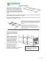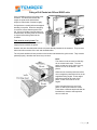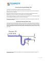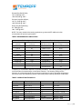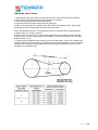
1
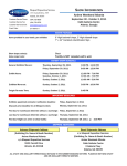
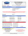
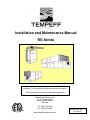
Installation and Maintenance Manual
RG Series
For long term reliability and proper function of Tempeff
equipment, it is essential that these instructions are followed.
These are general instructions, valid where applicable
Tempeff North America Ltd.
12-2130 Notre Dame
Winnipeg, MB Canada
R3H 0K1
Ph: (204) 783-1902
Fax: (204) 633-0496
www.tempeffnorthamerica.com
Bulletin No. IM 2-1
July 2010
Index
Index………………………………………………………….…….Page 1
General and Storage ……………………………………………Page 2
Instructions for lifting with a Crane…………………….……..Page 3
Mounting the individual sections……………………………...Page 3
Suggested framework……………………………………….…..Page 4
Hanging a unit from the roof………………………………..…..Page 5
Fitting Cell Packs into RG and RGSP units…………………..Page 6
Connecting Heating and Cooling Coils…………………….....Page 7
Installing Condensate Drain Traps……………………….……Page 7
Installation Requirements…………..………….………………..Page 8
Before Start-up Instructions………………………….…………..Page 8
Start-up/Commissioning Procedure……..……………………..Page 9
Maintenance Instructions…………….………………………….Page 10
Bearing Installation and Maintenance……..………………….Page 10
Lubrication Charts…………..………….………………..…….….Page 11
Tensioning V-belts………………………………………….…….Page 12
Warranty……...……………………………………………………..Page 13
Page |1
MANUAL
FOR TEMPEFF AIR HANDLING UNIT
WITH DUAL CORE HEAT EXCHANGERS
General
The instructions for assembly, operating and maintenance must be followed carefully in
order to achieve short and long term function and reliability. It is also a prerequisite for the
warranty to apply.
This manual shall be easily accessible to the staff responsible for the operation of this unit.
If the product is modified or changed without consent or instruction from Tempeff the ETL
listing (if applicable) may no longer be valid, and the warranty may no longer be valid.
Due to the custom nature of the product not all cases are covered in this manual. In the cases
where special items are included in the product, specific instructions can be obtained from
the local authorized Tempeff Representative, or by contacting the Tempeff Factory.
INTENDED USE
The unit is intended for comfort heating/cooling use only with no mixing of corrosive or
flammable gases.
Storage
Failing to follow the enclosed instructions may cause damage to the equipment, and void
warranty.
1) When storing both indoor and outdoor units openings and access doors must be
sealed
2) Equipment must be adequately protected from weather until final installation is
complete. Equipment stored outdoors must be heated. NOTE: Factory shrink wrap or
poly is not considered sufficient protection against the weather when stored in an
area exposed to the elements. The contractor is responsible for fully tarping the
equipment to prevent damage from weather or construction damage.
3) During extended periods of storage, it is important to rotate the fan and motor
bearings by hand at least once a month to prevent bearing damage. The bearings
should also be greased at the same frequency. Ensure bearings are not over greased
as it may result in ruptured seals and premature bearing failure once in operation.
4) To ensure equipment stays in as-shipped condition, and to avoid corrosion, inspect
the equipment twice weekly while in storage. If moisture is discovered on the
surface of the equipment immediately heat and ventilate the equipment to prevent
corrosion.
Page |2
Instructions for lifting with a Crane
When using lifting lugs to raise the unit spreader bars
must be used to prevent damage to the equipment. If
lifting lugs are not present each unit must be lifted with
soft straps under the lower framework. Since the
profiles used are slippery, the soft straps must be
secured to keep the straps from sliding off.
The unit is not designed to carry its’ own weight from
the upper framework.
In the smaller units the al-cell packs may be delivered
inside the accumulator chambers. Cell Packs must
be unloaded before lifting and reinstalled after the
unit is in place.
WARNING!
The upper framework and/or
extending parts of the unit
may not be used for lifting.
Mounting the individual sections
Unit shall be placed on a
solid and bare surface
suitable for the present
environment and
installation, such as
elevated for drain
connection if applicable.
Due to the weight of the
cell packs it is necessary
to ensure that all parts of
the unit are well
supported, not only
under the outer
framework but also in
between the outer frame.
Units wider than 1.5 m
supports not wider than
0.8 m (32 inches) from
each other.
A (Diagram 1 & 2) = self
adhesive gasketting shall
be used where the units
connect to each other.
Suitable high quality
caulking may be used in lieu of gasket. (Page 4)
Diagram 1
Connection Bolt – 5/16” x 5”
Diagram 2
Page |3
Caulk all Surfaces as Shown
Caulk Along Top
Surface of Section
Prior to placing upper
section
Caulking of Top and or Bottom Joints
Alternate Caulking of Split Unit Surfaces in lieu of Using Supplied Gasket
Outdoor units with sections stacked one on top of the other should be caulked prior to placing the
section on the other.
OUTDOOR SPLIT SECTIONS
For each split on an outdoor unit a
split cap is provided to bridge the
roof splits. This cap is an integral
part of the roof structure and must
be installed. Pre-drill pilot holes on
side of cap, then fasten using
common sheet metal screws. A
minimum of 2 screws per side are
required.
Joint Cap
Shipping Split
Gutters
Page |4
Suggested Framework
The unit shall be assembled on a solid and
plain surface. A frame of square steel bars is
recommended. It must be supported at each
end and at each unit connection. Support leg
to slab, or rod from roof shall also be fit at each
end and each unit connection as shown on the
picture.
When designing the frame the weight of the unit must be accounted for. Note that the weight of the
cell packs makes the units heavier than normal AHU’s.
Therefore units with widths greater than 1.5m (4.92 feet) must be supported by two outer bars. Max
width between bars is 800mm (32 inches).
Smaller RG units and all the RGSP units can be mounted
directly on rigid mineral fiber insulation boards placed on
the floor slab if it is level and if a water drain trap is not
required.
Leveling shall be made using water level or laser
instrument. If the unit requires a water drain trap the
height of the legs shall be calculated accordingly. See
page 7 for details.
Hanging a unit from the roof
If the unit is to be hung from the
roof, it must rest on a framework
supported by rods hanging from
the roof.
Support rods shall be centered
with the connections between
the sections of the unit and the
connection points between the
rods and the frame shall be
located so that the rods don’t
interfere with the opening of the
doors or the connection of ducts.
When designing and building the
supporting frame work (by
others) and rods the weight of
the unit must be taken into
consideration. The cell packs make the units
heavier than traditional air handlers.
Rods connect to the framework
(supplied by others) outside the unit
and center with the unit section
connection point.
Page |5
Fitting of Cell Packs into RG and RGSP units
Care in handling of the Al-cell packs must
be taken. For functional reasons the
cages are quite small and therefore
subject to deformation if treated roughly.
Cell packs are normally delivered wrapped
standing on a pallet. When the wrapping
is removed, ensure that the packs don’t
fall. If they do fall they normally take on a
rhomboid form and they must be reformed
to square before being fitted into the
chamber.
This must be done by hand! The
resistance that needs to be overcome is
largely friction between the plates.
Smaller units are often delivered with the cell packs already installed in the chamber. They must be
taken out before erection of the unit and reinstalled after.
The cell packs shall be slid into position on the beams and between the guide vanes. They must be
packed properly; otherwise the doors may not close.
Note!
The rivets must be oriented so that they
do not contact each other. Turn the
packs so that one set of rivets is on top,
and the next is on the bottom. See
picture.
When the unit contains packs more than
one row high they should be slid in on the
supplied dividing angles. These angles
should be placed at the ends of the
packs, so the cores slide in on the
angles.
Some unit sizes have one set of cell
packs of different size than the others.
These have a different depth and shall be
installed last, closest to the inspection
door on each row.
Page |6
Connecting Cooling and Heating Coils
In all cases, coil manufacturers installation instructions take precedence.
With water coils, ensure the connections are made so that leaving water from the coil is what the
entering air sees (counterflow).
Mounting an anti-freeze protection device on water coils is strongly recommended to prevent
damage to the coil due to freezing. Frost damage is not covered by warranty.
When installing couplings, do not apply undue stress to the connection. Use a backup pipe wrench
to avoid breaking the weld between coil connection and header.
Ensure care is taken when handling and connecting coils. Connections and pipes are fragile, and
can easily be damaged.
Installing Condensate Drain Traps
Units equipped with optional drain connection must have drain traps field provided and installed on
each drain. On both blow-through and draw-through units, the trap depth and the distance between
the trap outlet and the drain pan outlet should be twice the static pressure in the drain pan section
under normal operation for the trap to remain sealed. For example is the pressure is 2” W.C, 2P will
be 4” deep.
Pressure (P)
at the drain
This height will also determine the height H of the mounting framework as detailed on page 4. H
should be 4P, plus 2”.
Page |7
Installation Requirements
1. Service clearances must be maintained on the access side of the unit. Recommended
minimum clearances are equal to the section length if unit is equipped with single door, or
section length/2 if unit is equipped with double door, as clearance must be sufficient to open
doors. Consult dimensional diagram to verify required service clearances.
2. All relevant local and national codes (NEC or CEC) must be adhered to for clearances to
electrical connections. 1m or 36 inches is the minimum from the face of any electrical
enclosure to any wall or obstruction.
3. Installer is responsible for checking all damper bolts to ensure tightness, as during shipping
these bolts may become loose.
4. Installer is also responsible for checking tightness of all electrical terminals and connections,
as these connections may become loose during shipping and result in performance issues.
5. Consult wiring diagram to verify which electrical connections must be made in the field, such
as unit power, and field connections for the damper to be controlled by BMS. All wiring must
be performed in accordance with all applicable codes and ordinances. Warranty is voided if
wiring is not in accordance with these standards.
6. If unit is controlled by BMS, controls contractor must ensure the dampers are first on and
last off (after the blowers have been shut down) to avoid damage to the dampers.
7. If unit is equipped with blowers, ensure that shipping blocks have been removed from
isolation frame.
Before Start-up
1. Ensure that unit is completely and properly installed, and all ductwork is connected. Ensure
that all construction debris has been removed, and that filters are clean.
2. Verify that all electrical connections have been made, and check to ensure that correct
voltage has been applied to the appropriate sections. Check to ensure electrical connections
are tight.
3. Rotate the fans manually to ensure they rotate freely. Check to ensure that belts have been
tightened and sheaves aligned using a straight edge.
4. Verify that all damper blades close properly. Blades should be tight enough that a finger
cannot be pushed through but not so tight that the damper blade causes the housing to
deflect. Excessive tension can cause damage to damper section.
5. Check setscrews and nuts/bolts in damper linkages, bearings and fan wheels (if unit is
equipped with blowers). Note that equipment damage due to loose fasteners is
improper start-up and will not be covered under warranty!
After 48hrs:
a. Ensure unit has been properly locked out. Check tightness of all damper linkage,
bearing, wheel and sheave setscrews.
b. Check belt tension.
6. Verify that all holes in floors are sealed to prevent water leakage.
Page |8
Start-up/Commissioning procedure
When performing start-up and service, thorough safety precautions must always be taken. These
functions must always be performed by trained, experienced personnel. View “Before Start-up”
description before attempting start-up.
1. Verify that there is power to the fan motors
2. Verify that there is power to the unit control cabinet (consult wiring diagram for unit control
cabinet power terminals)
3. Enable supply air fans and exhaust air fans, and check for correct rotation. If incorrect
rotation, correct wiring to ensure fans rotate in proper direction.
4. Check supply and exhaust motor amp draws against rated amp draw on motor rating plate.
5. Test operation of damper motors.
a. Put switch S1 in position 1. Actuator M7 should operate continuously.
b. Put switch S1 in position 2. Actuator M6 should operate continuously.
c. If unit is pneumatic, consult sequence in shop drawing package to verify proper
damper motor testing
d. Put switch S1 back in position 0.
6. Put switch S2 in position 0. Check to see if dampers are in a “+” formation inside of unit,
closing off all air to building. Ensure all blades are firmly closed with no gaps.
7. Put switch S2 in position M. If Ambient air is above 68 deg F (20 deg C), increase
temperature on thermostat GT2 (exhaust t’stat) until it is above ambient temperature. If
expected supply air is above 59 deg F (15 deg C) increase temperature on thermostat GT1
(supply t’stat) until it is above expected temperature. Dampers should now cycle every 60
seconds.
8. Change GT2 back to 68 deg F (20 deg C), and GT1 back to 59 deg F (15 deg C). If the unit
is to be operated as a standalone unit, leave the S2 switch in M mode. If the BMS is to
operate the unit, put the S2 switch in A mode.
9. If the unit is controlled by BMS, contacts are used to control the damper mode. Consult the
wiring diagrams & sequence to verify wiring. Ensure dampers are first on and last off (after
blowers shut down) to avoid damage to dampers.
10. If unit does not operate as expected, consult wiring diagram and begin troubleshooting
wiring with your voltmeter. Ensure all wiring terminations have been tightened.
Page |9
Maintenance
Regular maintenance is necessary to ensure the efficient operation and long life of this unit. This
maintenance should be performed by, or supervised by qualified service personnel. A maintenance
schedule should be prepared for the unit based on its application and location.
Recommended Monthly Maintenance
1. Check for loose connections in the wiring
2. Check the voltage at the unit while it is in operation.
3. Check motor amperage draws against the rating plate values.
4. Inspect all contactors to ensure that they are clean and making good contact.
5. Clean or replace air filters if necessary.
6. Check all damper, linkages and damper actuators, adjust and tighten as required.
7. Check all belts ; adjust or replace as necessary.
8. Check operation of all safety controls.
Recommended Yearly Maintenance
1. Perform the monthly maintenance recommended.
2. Inspect the blower wheels and housing; clean if necessary
3. Inspect all setscrews on blower wheels and pulleys to ensure they are secured to their
respective shafts.
4. Inspect all operating and safety controls; clean and replace if necessary.
5. Inspect heat exchanger cores, clean if necessary.
BEARING INSTALLATION AND MAINTENANCE
NOTE: To prevent premature failure – please ensure greasing instructions below are applied. As
well, tighten bearing set screws, collars, and wheel lugs every four to six months.
ENGINEERING – BALL & ROLLER BEARINGS LUBRICATION
For bearings that are equipped with a hydraulic grease fitting threaded into the housing the
proper amount of lubricant in the bearing is important. Both excessive and inadequate lubrication
may cause failure.
The bearings should be re-lubricated while they are rotating (if it is safe to do so); the grease
should be pumped in slowly until a slight bead forms around the seals. The bead in addition to
acting as an indicator of adequate relubrication provides additional protection against the entry of
foreign matter and helps flush out contaminates in the
bearing.
By the time the slight bead has formed, it will be noticed that the bearing temperature will rise. It
is not uncommon for the temperature to raise as much as 30°F after re-lubrication. If necessary
to re-lubricate while the bearing is idle, refer to the recommended re-lubrication grease chart
tables on the following page for various sizes of the bearings.
LUBRICANT - STANDARD BEARINGS
All bearing units are pre-lubricated at the factory with lithium soap grease, which is compatible
with multi-purpose grease readily available from local suppliers. The lubricant selected for factory
lubrication uses a highly refined mineral oil with a high viscosity index, thickened with lithium soap
to conform to NLGI grade 2 consistency. A suitable additive package is added to protect the
highly polished rolling contact surfaces from corrosion and oxidation of the lubricant. The
lubricant is satisfactory for an operating temperature range of -30°F to +250°F.
Select standard industrial grade greases that conform to the following specifications for optimum
bearing performance:
P a g e | 10
General Duty Ball & Roller;
58-75 SUS @ 210°F
450-750 SUS @ 100°F
Premium Duty Ball & Roller;
68-75.1 SUS @ 210°F
600-750 SUS @ 100°F
Heavy Duty Roller Bearing;
82 SUS @ 210°F
886 SUS @ 100°F
NOTE: For heavy loaded roller bearing applications, grease with EP additives is often
recommended for optimum performance.
TABLE: RECOMMENDED LUBRICATION
Shaft Size
(inches)
Ball Bearings
Grease Charge
(ounces)
Roller Bearing
Shaft Size (inches)
Grease Charge (ounces)
¼ to 3/16
0.03
1-3/16 to 1-1/4
0.1
½ to ¾
0.1
1-3/8 to 1-7/16
0.22
1-1/4 to 1-1/2
1-11/16 to 115/16
0.15
1-1/2 to 1-11/16
0.32
0.2
1-3/4 to 2
0.5
2 to 2-7/16
0.3
2 to 2-3/16
0.55
2-1/2 to 2-15/16
0.5
2-1/4 to 2-1/2
0.65
3 to 3-7/16
0.85
2-11/16 to 3
0.85
3-1/2 to 4
1.5
3-3/16 to 3-1/2
1.25
-
-
3-15/16 to 4
2.5
-
-
4-7/16 to 4-1/2
3.1
Frequency of re-lubrication depends on operating conditions. The bearing operating temperature
is the best index for determining a re-lubrication schedule. The following chart gives the
frequency of re-lubrication based upon continuous operation for various operating temperatures
and can be used as a satisfactory guide for determining when bearings should be re-lubricated.
TABLE: LUBRICATION FREQUENCY
Speed
Temperature
Cleanliness
Greasing Interval
100 RPM
Up to 120 °F
Clean
5 months
500 RPM
Up to 130 °F
Clean
2 months
1000 RPM
Up to 210 °F
Clean
2 weeks
1500 RPM
Over 150 °F
Dirty
Weekly
Any speed
Up to 150 °F
Dirty
1 week to 1 month
Any speed
Over 150 °F
Dirty
Daily to 1 week
Any speed
Any temperature
Very dirty
Daily to 1 week
Any speed
Any temperature
Extreme Conditions
Daily to 1 week
P a g e | 11
TENSIONING V-BELT DRIVES
1. Ideal tension is the lowest tension at which the belt will not slip under peak load conditions.
2. Check tension frequently during the first 24-48 hours of operation.
3. Over-tensioning shortens the belt and bearing life.
4. Keep belts free from foreign material that may cause slip.
5. Make V-drive inspection on a periodic basis. Re-tension when slipping occurs. Never apply
belt dressing as this will damage the belt and cause early failure.
Check and tighten belt tension. The following procedure is recommended for tightening belts:
a. Measure span “X” shown in Figure A.
b. At the center of span length “X”, apply a force perpendicular to the span and large enough to
deflect belt 1/64” for each inch of span length. Example – the required deflection for a 40” span
would be 40/64” or 5/8”.
c. Compare the force applied with the values given in the table below. If the force is between the
minimum and maximum range shown, the drive tension should be satisfactory. A force below the
minimum value indicates an under tightened belt and a force that exceeds the maximum value
indicates an over tightened belt.
P a g e | 12
Product Warranty
Warranty on Tempeff Heat Recovery devices is one (1) year from unit start-up date or 15
months from date of shipment from our factory. Tempeff heat exchanger modules are
warranted against material or manufacturing defects for a period of 10 years.
Our warranty applies for original shipment on all parts and components fabricated by or
installed by us with the exception of air filters, and blower belts.
Within the one year warranty, replacement parts will be shipped collect and charged to
customer account with credit being issued after receipt of, and examination of the
returned parts: freight prepaid to the factory.
This warranty does not include freight, labor, or sales tax that may be incurred by the
purchasers and is subject to the following conditions:
1) The unit shall be installed by a qualified heating or ventilation contractor in
accordance with the provisions of the service manual.
2) The unit shall have been installed in accordance with all national and local codes.
3) The unit shall have been subject to only normal use in service and shall not have
been misused, neglected, altered or otherwise damaged.
4) The unit shall have been operated within its published capacity and with the
prescribed fuel.
5) All automatic controls shall have been operative at all times.
6) The heat exchanger has not been subjected to corrosive environments
7) There is no evidence of tampering or deliberate destruction.
8) Frost damage to coils is not covered by this warranty
No representative of Tempeff or any of its distributors or dealers is authorized to assume
for Tempeff any other obligations or liability in connection with this product, nor alter the
terms of this warranty in any way. This warranty is limited to the express provisions
contained herein and does not extend to liability for labor or travel costs incurred in
replacing defective parts.
Authorization to return any alleged defective parts must be obtained from the factory
before the part is transported and the owner shall prepay the transportation charges for
any alleged defective parts. Tempeff will not accept charges for parts purchased unless
the conditions of this warranty have been satisfied.
The express warranties herein contained are in lieu of other warranties, expressed or
implied, including the warranty of merchantability and of fitness for any particular
purpose. Tempeff shall not be liable for damages, including special, incidental, or
consequential damages arising out of or in connection with the performance of the heat
recovery devices, or its use by the owner. Tempeff liability is limited exclusively to repair
and or replacement of the defective part. Parts can be obtained from Tempeff North
America, 12-2130 Notre Dame, Winnipeg, Manitoba, R3H 0K1, on the basis that credit
will be issued if defective parts returned qualify for replacement pursuant to the terms
and conditions of this warranty.
P a g e | 13