1
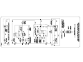
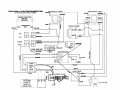
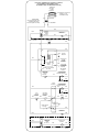
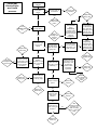
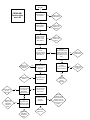
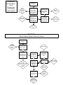
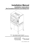
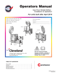
Statement of Responsibilities
This document is for use by experienced and trained Qualified Cleveland Range, LLC Authorized Service
Representatives who are familiar with both the safety procedures, and equipment they service.
Cleveland Range, LLC assumes no liability for any death, injury, equipment damage, or property damage
resulting from use of, improper use of, or failure to use the information contained in this document.
Cleveland Range, LLC has made every effort to provide accurate information in this document, but
cannot guarantee that this document does not contain unintentional errors and omissions.
The information in this document may be subject to technical and technological changes, revisions, or
updates.
Cleveland Range, LLC assumes no liability or responsibility regarding errata, changes, revisions, or
updates.
Qualified Cleveland Range, LLC Authorized Service Representatives are obligated to follow industry
standard safety procedures, including, but not limited to, OSHA regulations, and disconnect / lock out /
tag out procedures for all utilities including steam, and disconnect / lock out / tag out procedures for gas,
electric, and steam powered equipment and / or appliances
All utilities (gas, electric, water and steam) should be turned OFF to the equipment and locked out of
operation according to OSHA approved practices during any servicing of Cleveland Range equipment
Qualified Cleveland Range, LLC Authorized Service Representatives are obligated to maintain up-to-date
knowledge, skills, materials and equipment.
Cleveland Range, LLC
Ph: 1-216-481-4900
Fx: 1-216-481-3782
1333 East 179th St., Cleveland, Ohio, U.S.A. 44110
Visit our Web Site at www.clevelandrange.com
CLEVELAND RANGE
SEQUENCE OF OPERATIONS
Electric Boiler Base
1. Supply voltage is sent to the primary of the Control Transformer.
x 115 VAC is sent from the secondary of the Control Transformer to the on/off rocker
switch.
2. To turn the unit on, depress the red on/off rocker switch.
x 115 VAC is sent to the upper cabinets and terminal block in control box.
x 115 VAC is sent to normally open drain valve closing it.
x 115 VAC is sent to L1 and L2 of the water level board.
3. With the water level board energized and no water in the boiler
x 115 VAC is sent from the WF terminal to the fill solenoid.
x The fill solenoid opens and the boiler fills through the drain valve.
x The water fills to the low probe shorting it to ground
x 115 VAC is sent from the HTR terminal through the normally closed contacts of the
highlimit pressure switch to contacts of the ice cube relay and the amber reset switch,
energizing the amber light.
4. When the momentary amber switch is depressed 115 VAC is sent to the coil of the ice cube
relay closing it.
x The relay latches itself through a jumper to the coil.
x If either the high-pressure switch or the low water cut of switch opens, the latch
circuit opens.
x When the contacts close the amber light will energize and the process may begin
again.
x The relay contacts close sending 115 VAC through the normally closed contacts of the
operating pressure switch to the coil of the contactor(s). .
5. With 115 VAC to the coil of the contactor(s).
x The contactor closes.
x Supply power is sent to the elements.
6. The water in the boiler is heated to steam.
x As steam is generated and pressure builds the air is pushed out through the steamtrap.
x When steam goes through the steam trap and heats it to 192 degrees it closes.
7. Pressure builds in the boiler to the set point of 8-10 PSI (except 36CEM16 or pressure
steamers that are set at 5PSI).
x The operating pressure switch opens and the heat circuit is de-energized.
x When the pressure drops below the set point the heat circuit is energized and the heat
process begins again.
8. Water continues to fill until the high probe is grounded.
x When the high probe is grounded the WF terminal on the water level board is deenergized.
x The fill solenoid closes until the high probe is ungrounded for 05 seconds.
x If the water level drops below the low probe for more than 20 seconds the WF terminal
is energized and the water fill circuit begins again.
9.
When the unit is turned off, by depressing the red rocker switch,
x 115 VAC is removed from the heat circuit.
x 115 VAC is removed from the drain circuit and the normally open drain valve opens
allowing the unit to drain.
x 115 VAC is sent to the 3-minute timer.
x The three-minute timer will energize the fill solenoid for 3 minutes while the steamer
drains.
CLEVELAND RANGE
SEQUENCE OF OPERATIONS
Electric Boiler Base
With Secondary Low Water Cut Off Switch
1. Supply voltage is sent to the primary of the Control Transformer.
x 115 VAC is sent from the secondary of the Control Transformer to the on/off rocker
switch.
2. To turn the unit on, depress the red on/off rocker switch.
x 115 VAC is sent to the upper cabinets and terminal block in control box.
x 115 VAC is sent to normally open drain valve closing it.
x 115 VAC is sent to L1 and L2 of the water level board.
x 115 VAC is sent to the open contacts of the low water cut-off switch.
3. With the water level board energized and no water in the boiler
x 115 VAC is sent from the WF terminal to the fill solenoid.
x The fill solenoid opens and the boiler fills through the drain valve.
x The water fills to the low probe shorting it to ground
x 115 VAC is sent from the HTR terminal through the normally closed contacts of the
operating pressure switch to coil of the contactor(s).
x The rising water also raises the float on the low water cut-off switch closing it.
x 115 VAC is sent through the normally closed contact of the high-pressure switch to the
amber reset switch, energizing the amber light.
4. When the momentary amber switch is depressed 115 VAC is sent to the ice cube relay
closing it.
x The relay latches itself through a jumper to the coil.
x If either the high-pressure switch or the low water cut of switch opens, the latch
circuit opens.
x When the contact close the amber light will energize and the process may begin
again.
x The relay contacts close sending 115 VAC to the coil of the contactor.
5. With 115 VAC to the coil of the contactor(s).
x The contactor closes.
x Supply voltage is sent to the elements.
6. The water in the boiler is heated to steam.
x As steam is generated and pressure builds the air is pushed out through the steamtrap.
x When steam goes through the steam trap and heats it to 192 degrees it closes.
7. Pressure builds in the boiler to the set point of 8-10 PSI (except 36CEM16 or pressure
steamers that are set at 5PSI).
x
x
The operating pressure switch opens and the heat circuit is de-energized.
When the pressure drops below the set point the heat circuit is energized and the heat
process begins again.
8. Water continues to fill until the high probe is grounded.
x When the high probe is grounded the WF terminal on the water level board is deenergized.
x The fill solenoid closes until the high probe is ungrounded for 05 seconds.
x If the water level drops below the high probe for more than 20 seconds the WF
terminal is energized and the water fill circuit begins again.
9.
When the unit is turned off, by depressing the red rocker switch,
x 115 VAC is removed from the heat circuit.
x 115 VAC is removed from the drain circuit and the normally open drain valve opens
allowing the unit to drain.
x 115 VAC is sent to the 3-minute timer.
x The three-minute timer will energize the fill solenoid for 3 minutes while the steamer
drains.
ELECTRIC GENERATOR CONTROL WIRING
CALIFORNIA CODE (ASME CSD-1)
(INTERMITTENT BLOWDOWN OPTION)
FUSEBLOCK
P/N 109374
FUSES
P/N 109380
FU
TO LINE SIDE OF CONTACTOR
PHASES 1 & 3 OR
TO TERMINAL BLOCK
FU
TRANSFORMER
P/N 20535 (208V-480V UNTS)
P/N 20536 (600V UNITS)
P/N 107040 (380V-415V UNITS)
H4
H1 PRIMARY
X1
X2 SECONDARY
GRA
3
BRN
3 MINUTE
INTERVAL
TIMER
P/N 20478
2
WATER VALVE
P/N 22223
BLU
BLU
1
POWER SWITCH
P/N 19993
POWER ON
WHT
BLU
R
WHT
WF
L2
GRN
BOILER
GROUND
COM
BLK
L1
HI
CONTROL
CIRCUIT
BLK WATER LEVEL
PROBE
EXTENSION
P/N 62452
RED
LOW
WATER LEVEL CONTROL
P/N 23198
HTR
YEL
OPERATING
PRESSURE
SWITCH
P/N 19947
LOW WATER
CUTOFF PROBE
EXTENSION
P/N 62453
(REF: PROBE)
P/N 16671
CONTACTOR COILS
AS REQUIRED
P/N 03506 OR 03509
WHT
YEL
A
B
WHT
A
RELAY
P/N 106561
7
BLK
4
B
CONTACTOR COILS
AS REQUIRED
P/N 03506 OR 03509
WHT
RED
A
B
WHT
LOW
WATER
SWITCH
BLK P/N 19995
HIGH LIMIT
PRESSURE
SWITCH
ORN
ORN P/N 19947
A
9
3
PNK
B
RESET
WHT
A
PRP
RESET SWITCH
P/N 19994
PRP
6
PRP
A
B
WHT
DRAIN VALVE
P/N 22221
RED
RED
INTERMITTENT BLOWDOWN OPTION - DRAIN VALVE WIRING
WHT
3
RED
2
RECYCLING
INTERVAL
TIMER
P/N 104716
DRAIN VALVE
P/N 22221
RED
RED
1
104870 E
Boiler won't build
pressure
PROBLEM:
Electric Boiler
won't build
pressure
Is the red light on
in the power
switch?
No
Is there power to
the steamer?
No
Connect power
to steamer.
Replace the
latching relay.
Yes
Yes
See
Steamer won't
fill.
No
Replace the
on/off rocker
switch
No
Yes
With the High
Limit pressure
switch
temporarily
bypassed, does
the Amber light go
off when the reset
switch is
Yes
depressed?
Is there water in
the sight glass?
Yes
Is the Amber light
on in the reset
switch?
Yes
Replace the
water board
Replace
the high limit
pressure
switch
No
No
No
After depressing
the reset switch,
does the Amber
light go off?
Does this boiler
have the optional
Secondary Low
Water Cut Out?
No
With a jumper
from terminal 6 to
9 on the latching
relay, does the
Amber light go out
with the reset
switch depressed?
Yes
With the SLW CO
switch
temporarily
bypassed, does
the Amber light go
off with the reset
switch depressed?
Yes
No
No
Repair
or Replace the
probe circuit.
Is there 120 VAC
between terminals
L2 and HTR on the
Yes
water board with a
jumper between
Low and C?
Replace the
SLWCO switch
Yes
No
Is there 120 VAC
between
terminals L2 and
HTR on the water
board?
Is there 120 VAC
to the coil(s) of the No
contactor(s)?
Yes
Is there 120 VAC
to the coil(s) of the
contactor(s) with
the operating
pressure switch
temporarily
bypassed?
No
Is there 120 VAC
to terminal 6 on
the latching relay?
Yes
Replace the
Reset switch
Does the contactor
pull in?
No
Replace the
contactor
No
Replace the
element.
Replace
the operating
pressure
switch
Yes
Is there an amp
draw at the
element?
Yes
Is there allot of
steam coming out
the drain?
Yes
Replace the
steam trap
Replace the
latching relay
Yes
Yes
Replace the
latching relay
No
No
With
Elements heating
the water, the
Boiler is making
steam. Check for
leaks.
Boiler
won't fill.
Yes
PROBLEM:
Electric boiler
won't fill
Is there power to
the steamer?
No
Supply power
to the steamer.
No
Supply cold
water to the
steamer.
Yes
Is there water to
the steamer?
Yes
Is there 120 VAC
between the L1
and L2 on the
water board?
Replace the
on/off rocker
switch .
No
Yes
Is there
120 VAC between
L2 and W F on the
water board?
No
No
Is there
120 VAC across
the coil of the fill
solenoid?
Is there
debris on the HI
probe extension?
Yes
Yes
Replace the fill
solenoid
No
Is
water leaving the
fill solenoid?
Clean or
replace the
probes
extension.
Yes
Replace wiring
to drain
solenoid.
No
Does
the steamer have
the optional
intermittent
blowdown timer?
No
Is there
120 VAC across
the coil of the
drain valve?
Yes
Yes
Replace the
wiring to the
intermittent
blowdown
timer .
No
Is
there 120 VAC
between terminals
2&3 on the timer?
Is water draining
from the
generator?
Yes
Yes
Replace the
intermittent
blowdown
timer.
Replace the
drain valve.
No
Replace the
water board
Yes
Yes
Replace the
wiring to the fill
solenoid.
Remove
the wire from the HI
terminal on the water
board. Is there 120
VAC between L2 and
WF?
No
If water
is leaving the fill
solenoid and not
draining from the
generator where is it
going? check for
leaks..
No
Replace the
wire to the Hi
probe.
PROBLEM:
Electric Boiler
Over
Pressurizes
(15# Safety
valve opens)
Boiler over
pressurizes
Replace
operating
pressure
switch
No
Does operating
pressure switch
open at proper
setting (check
service manual for
that steamer)?
Yes
Does the 15#
safety valve open
with little or no
pressure on the
gauge after it has
been replaced?
Yes
Does the contactor
continue to pull in
with operating
pressure switch
open?
Yes
Replace
contacto.r
Yes
Replace the
weeper valve.
No
Replace the
safety valve.
No
Does the pressure
in the gauge
continue to rise
with no voltage to
contactor coil?
No
Delime the
boiler.
PROBLEM:
Electric Boiler Stops Producing Steam
Boiler stops
steaming
Replace
operating
pressure
switch.
No
Does the amber
light in the reset
switch come on?
Delime boiler
Yes
Is the temperature
sensitive dot
(surrounded by a
yellow circle) on
the water board
white?
Yes
Yes
No
Replace
the water board. It has
reached a temperature of
over 180
degrees.
Does boiler have
the optional
Secondary Low
Water Cut Out?
No
No
Yes
Will Boiler stop
making steam
with SLW CO
temporarily
bypassed?
Yes
No
Replace
Secondary Low
Water Cut Out
switch.
Is high pressure
switch opening
prematurely?
No
Replace the
water board
No
Does SLW CO
open and close as
float is moved up
and down?
Are the probes
covered with
scale?
Yes
Install delay
timer for
SLWCO
Yes
Replace high
pressure switch
PROBLEM: Electric Boiler Overfills
Replace 3
minute timer
Boiler over fills
No
Replace the fill
solenoid
No
With the HI probe
emersed in water
is there 120 VAC
between terminals Yes
L2 and W F on the
water board.?
With the wire
removed from
terminal 1on the 3
minute timer, is
there 120 VAC to
the fill solenoid?
With a jumper
across terminals
HI and C on the
waterboard, is
there 120 VAC
between L2 and
WF?
Yes
Yes
No
The probe
circuit is open.
Check continuity of the
probe wire and
probe.
PROBLEM: Transformer continues to fail.
Transformer Fails
start
Leave
fuse in place.
Transformer
could have been
bad.
No
After a 2 amp
inline fuse is
placed on the
secondary, does
the fuse open?
Yes
Check
the resistance of
all the solenoid coils.
Compare to chart.
allow for 10 %
deviation.
Replace ;the
water board