1
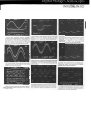
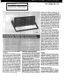
.
~~llJrl;~
"
PM'3310N&
..- ~ PM
. 3323
With compliments
Helmut Singer Elektronik
www.helmut-singer.de [email protected]
fon +49 241 155 315
fax +49 241 152 066
Feldchen 16-24 D-52070 Aachen Germany
appIies to both channeis, Simuhaneously, and
SynchronouSIy.It ofters a full 2 ns resolution for
&ach channel, tor repetitive signals and single
events! And random sampling permits the use of
higher time base speeds for repetitive signals, so
that the full 300 MHz of the instrument can be
used and stored. Each channei is also provided
with a dual, fast peak-detector which permits the
capture of events down to 3 ns, even when slow
time base speeds are used. This is not onIy
useful to catch short glitch-type signals over
Ionger time windows, It also allows the instrument to accurately digltize and display high frequency signals which are modulated in amplitude by a lower frequency, wlthout aliasing. For
the slowest 01 signals, a roll mode is provided.
The roll mode can be triggered, if desired, 10stop
at any significant signal detail.
Trlggerlng
and
Delay
Capabilities
The PM 3323 Cf PM 3320A can be triggered
from a choice of internal and external signal
sources.Pre-trigger
01 up to one lull screen is
JX)Ssible, not only in the direct acquisition modes,
txJt also at the higher time base speeds, thanks
to the instrumenfs random sampling technique.
Extensive post-trigger recording with delays of
up to 1000 screen lengths permits analysis 01
small signal details out cf lang and complex
signals. In addition, the REST ART lunction, which
enables the user to quickly 'zoom in' on a point of
interest, make analysis fast and simple and
provide a better alternative to the traditional
Delayed Sweep arrangement. Trigger level can
be checked in the CRT cisplay lor fast setup, for
all selected trigger sources, whether internaI, or
external.ln addition to normal trigger delay, the
delay can also be used to give an intemaJ time
delay after an external event. Both models also
otter excellent TV bigger capabillties. (See also
PM 8917.\
ExtensiveAcqulsitionand Display
Functlons
The PM 3323 and PM 3320A have extensive
acquisition, calculation and display functions to
capture exactly the signals of interest and quickly
extract Ihe information arId measurements required. 80th models otter an absolute minimax
mode ('envelope' mode) Ihat creates a cumulatlve record of signal amplitudes over the measuring period. Also availabie are stop on difference
and save on difterence modes. These allow
signals outside a predetermined
band to be
captured. after which acquisition either stops
(stop on difference) or continues after saving the
waveform in a register (save on difterence). In
both cases the signals are time and date stamped
10 help reiste intermittent faults to possible external causes. In combination with the other acqui-
Inputsand SignalAcquisition
The PM 3323 arid PM 3320A have the power
Storage
and versatility to cover a wide range of appjicaSignals trom each channel can be stored in
tions',Two signal inputs ~e provided, each with
each of,four 4k memories. This allows tor easy
a ~01C8 of 1 Mn, or .san Input impedance. '!"he
companson of waveforms, or the display of refbullt-ln 50n terminations are protected agalnst
erences. A uniqtle, multipie-single-shot
mode
damage through overtoads by a combination ofWithallows
tor quick and autornatic storage of up to
compliments.doc
sottw,are and thermal protection.
tour dual-channel acquisitions whlch occur rapd
,CaJibrat~
~ltage ~ftset of up t? 1000 x each
succession. All waveforms are kept with all releInput sensltivlty permits the full utillZation of the
vant acquisition parameters, such as sensitivity.
instrument's 10 bit ~ertlcal resolution even when
time base. and delay settings at the moment of
examlnlng small signals present on large DC
recordlng. Areal-time clod( provides automatic
offsets. Even if the magnitude of this DC oftset is
'time stamps'. Full cornpatibility with GPIB/IEEEunknown the PM 3323 or PM 3320A can mak,e
488* and RS-232C enables almost unlimited
the compensation
,automatically
USlng thelr
recording of waveform data on extemal devices.
AUTQ-OFFSET
facll~.
-:0 enab~ a~urate
measurements on nOtsy signals, whlch IS often
~
sition modes such as pre- and post-triggering,
the case
high ba~dth low level signals, Display and Soft Keys
~ averaging mode IS Indi~nsable.
The averThe PM 3323 and PM 3320A have a large 10
offseI arid restart, the PM 3323 and PM 3320A
otter exceptional versatility in capturing and
analyzing exactly the sign~1of interest. A complete measurement center In one unit.
aglng mode reduces the nolSe: drastically, enabllng a clean,~I~ay 10be achleved even ,at the
hlghest sensltivi~es. Further, the PM 3323 s fast
500 MS/s sampilng rate (250 MS/s on PM 3320A)
x 12 cm CRT screen. The center 8 x 10 cm ares
is exclusively used for waveforms. The edges of
the screen the show acquisltlon para~
of
liv.
.innal.
nr
",f
nrAoli
,e".
~;~":~c
PMß320A.&'BM,ß323
,.
,. ~ID~
~
.,~~
,
~
---
--
---
"-"-
r
Cir.;;.:
forms. Thls clear separation of signal traCesand
parameters eases Interpretation of results. All
softkey displays are to the right of the display and
adjacent to the softkeys. A separate numeric
keypad allows dlrect input of pertinent data such
as offset and delay.
Operationand UserFrlendliness
All main functions are directly accessible to the
user, without the need to leam soft-key menus.
This also eliminates the time consuming need to
back up through various levels ot menus to
change instrument settings.And Phillps 'Greenbutton' Autoset provides tor even taster set-ups
by automatically determining the optimum acquisition parameters tor any input signal. This is
a great help in flndlng and viewing unknown
signals.Once captured, wavetorms are immediately dispiayed, and without Interference from
text or menus. All texts are dispiayed aJongthe
screen edges, with only channel ident/tication (A
or B) dlspiayed wlth the relevant trace. The PM
3323 and PM 3320A even show a waming when
aliasing due to undersarnpling isdetected! The
logical front panel layout tollows the traditional
concepts of clearly grouping Input channeis,
time base tunctions and trigger tunctlons. This
Iogical approach makes the use of this advanced
DSO possible righl from the start.
SetUp Memories
Both models have user-programmable setup
feature allows even greater aase ot use, providing automation without a computer. This ensures repeatability of tests and their results.Up to
tully 250 user-detined instrument setups can be
stored tor measurements of user-specific interest. These instrument setups can also be linked
together to form sequences ot lest steps, or can
be recaJled at random.
Versatile MeasurementFunctions
Once a signal has been acquired, a tull range
ot measurement and calculation functions to
extract exactly the information needed trom the
signal are availab1e. Measurements ot voltage
and time dlfferences between the cursors positioned on a single wavetorm are possible. In
addition cornparative measurementsto be made
between !wo wavetorms recorded on channel A
and channel B, or between separate waveforms
stored in any ot the instruments tour memory
registers.Not only absolute and relative time and
VOItage measurements are possible,but also
phase measurements. In each case, all that's
necessary is to position the cursors on the desired part of the signal or signals concemed,
make a simple menu selection ot the required
measurement, and the numeric result is immediatety dlspiayed on-screen. To enhance and
quicken speciflc application measurements the
PM 3323 and PM 3320A also otter tull automatic
cursor posltioning. In this mode the cursors are
automatically positloned with respect to user
deflned reterence levels. The choice ot refer-
encelevelsare:
MIN PEAK the most negative signal value
measured
MAX PEAK the most positive signal value meas-
ured
ABS VOlT an absolute voltage level set by the
user
PROB LOW the voltage level thaI corresponds
with the Iower flat part of a pulse
PROB HIGH the voltage level thaI corresponds
with the upper flat part of a pulse
The !Wo PROB reference levels are derlved
from the amplitude histogram cf the signal being
measured. This ellminates the influence of overshoot, preshoot, and ringing on time measurements derived from these amplitude levels. These
reference levels define the 0 % and 100 % vaJues
values
tor cursor positioning. The cursors can then be
automatically placed at any value between -50 %
and + 150 % relative to these reference levels.
Cursors can also be used as 'Smart-Start cursors'. When the cursors are pIaced over any
signal detail of interest, the activation of 'Restart', automatically reestablishes proper delay
and sampling speed to acquire that detail with
maximum resolution.
Advanced Signal Processing
Modes
Constructlon
The sturdy construction provides for a varlety
ot operating configurations. At just under 18 kg,
it can easily be carried trom one Iocation to another, and the carrying handle doubles as an
adjustable stand. Scopecart PM 8991/04 ofters
further rnobility. In addition, a radtmountable
version tor use in standard 19 inch racks is also
available.
,.7?18PM3323aridPM332OA~
/8. ~
~
GWnf8r.
8ecaUN« fIe 10x 12an. ~
sJzesm fuU8 x 10an dsdcSJ8dIr*» .. . ~ 8xt
/8
intefferingMlhthecfSJWajl8d~
The PM 3323 and PM 3320A offer more than
signal measurements alone. A wide range of
signal-processing modes allow you to expiore
more deeply into your acquired signals. and
perform calculations that reveal hidden data and
relationships.The basic arithmetic tunctions of
add, subtract. multiply and divide are supplemented by signal differentiation and integration.
as weil as amplitude histograms. the appiication
of digital filters and an optional FFT facility tor
signal representation and analysis in the frequency domain.
System Use
The interface option on both models otters JulI
GPIB/IEEE-488 and RS 232C capabilities. All
controls can be set or read. Waveform data can
be taken trom any of the tour memories. or be
sent back to the scope ,tor example when Ioading a template for the 'stop on difference ' mode.
All 250 user defined setup memories can be set
by the controller, as weil as called by the controller. This drastically reduces bus traffic and significantly speeds automatic testing applications.
Hard Copy
Each model is equipped with an analog output
to drive an analog XY recorder. The operator can
seiect any waveforrn in any memory to be drawn
by the recorder. Instruments equipped with the
interface option provlde direct 0U1putto
plotters or printers. A digital plot or pt'int --. -.
any waveforrnis possible.aIong with aiphanumeric data pertinentto that waveforrn.
2. RestaIt
fastzoom.;,«I""
äW. AI ftl8t's
n-.Iy
is 10kJc.- .. QI-. 8IOImd
.. .,.. of
,
~ ,
ttIeRes8rtk8y.A ~ ~
is
"..
. . ~
~
,. #JeluI ~.
,.
» "., Ire ..
of
PM 331b~& PM 3323.
Specifications
Technical Specifications
Uniess
stated
aß specifications
refer 10 both PM
3323 and PM 3320A.
CRT
Philips 180 mm rectangulartube with 16 kV
aa:eleration potential and P31 phosphor (GH).
100 mm x 120 mm useful screen area. 80 mm x
100 mm tor traces.
Readout: Three separate areas reserved for
front panel setting information, register parame-
12.A tJIfw.x.".of Ihe mIftI fadIity -inI8g/'8te.." ".,...
Ihe inIegra/of ltIe signal ~
/he ters on softkeymenus
~
A convwWnt displsy Ior UM in 'energy' Gratfcule: InternaJwith % indications. Illumina~forBDmp/e.
tion continuously variable
Autoset
Sets display. text, verticaJmode, horizontal mOde
and trigger coupling in a predefined position.
Other parameters depending on signaJ so that
available signals-are COrrectly recorded and
displayed.
Signal
Acqulsitlon
Sampllng Type:
Realtime: PM 3323 100 ns/div...360s/div.
PM 3320A 200 ns/div...360s/div.
Equivalent time: PM 3323 5 ns/div...SOns/div.
PM3320A5 ns/dIv...100ns/div.
13;Fuirt..,.ptoces8ngglv...
~t6t1»nsion ~-MaximumSampIe Rate:
shotsburledin noise.77IMe~
unmce
~
Real time: PM 3323 500 MS/s.
~
NlatcanbB 'awraged'/f noiseexIs'-...
PM 3320A 250 MSis.
once~ 8IIda~
cannotbe useQ'.
~ IhePM EquivaJent time: 10 GS/s.
Externeiclock: 50 kS/s.
Vertical Resolution:
10 bits or 0.1% 01 tu" scale
Voltage resolution:
50 I1V
Maximum Horizontal Resolution
Single channel (single shot)
PM 3323 100 ns/div...500 jJ,s/div: 512 sampies/
acquisition: 1 ms/div...360s/div: 4096 sampies/
acquisition
PM 3320A 200 ns/div...500 jJ,s/div: 512~
acquisition; 1 ms/div...360s/div: 4096 samples/
14. The opfonal
FFT hIJCt/on wi#I Nl8dBlNB
Witw»wIng
(18ctanguIar. H8mWIg or Hatr8ng) and bar
/ogSIHhmicscsIng ~
fast ~~
and ~y
~ power speara in .,. ~
dom8n.
or
of
PM 3320A 5 ns/div;..100 ns/div: 512 samples/
acquisition; 200 ns/div...360s/div: 2048 samples/
acquisition
Acqulsltlon Tlme:;Realtime 10.24 x time/division (exclusive delay time). Equivalent time 2s
tor 5 ns/div. (inputsignaJ dependent): 10 ms tor
100 ns/div. (99% probabilitY ot all sampIes being
updated).
Sources: ChA, -ChA, ChB, oChS
Modes: ChA, ChB, ChA and ChB, ChA + ChB,
ChA - ChB, ChB - ChA, -ChA oChS. Average and
MINIMAX possiblein aJl modes.
Samp4e Dlfference Between ChA end ChB:
80th channels are sampled simultaneously
%200 ps.
Acqulsltlon
Processlng:
Absolute minimax. (envelope)
Averaging
Save on difference
Stop on difference
Channels A andB
Input Impedance (High Z): 1 MO in parallel with
14 pF
Input Impedance (500): V.S.W.R. 1.2:1 at 200
MHz
Maximum Input Voltag. (High Z): 300V (DC +
AC peak) at 1 MH,
Maximum Input Voltage (500): 5V DC and
r.m.s.; 50 V AC peak. Protectedagainst selection with unsafe vo/tage on input: connector.
Deflection Coefflcients: 5 mV/div...5V/div. in
1-2.5 sequence. (Continuous control between
steps)
Error Umlt (Variable Calibreted): Overall 2010.
Add ~/o in min./max. mode and in 100 ns/div
fange
DynaInlcRange:10~
DCOftMt
A8ng8 ~.
5 mV/cIv...20mVIdiY..
t5V
5 mV
50 mVIcIv...200mV,*.
tS)V
WrrN
500mV/dY...5V/dY.
tDV
_mV
Shm
~
:t5 dIVI8Ions
Frequency A88P0nse:
acquisitJon
PM 3323 OC...300 MHz (-3 dB)
Single chan"" (repetitive or single
scan)
- sampies/ PM 3320A DC...200 MHz (-3 dB)
PM 3323 5 ns/div...50 ns/div: 512
AC coupled Iower -3 dB point wiIh 500 input 10
acquisition; 100 ns/div...360s/div: 4O96samples/
Hz; AC COUpledlower -3 dB point with high Z
acqulsition
input 1 Hz. Bandwidth limiter reduces bandwidth
PM 3320A 5 na/dIv...100 na/div: 512 samplesl
1020 MHz.
acquisition; 200 na/div...360a/div:4096 samples/
AI.etlme (0.35/Bendwfdth): PM 3323 1.16 ns
acquisition
PM 3320A 1.75 ns
Dual channeI (single shot)
CMAA: 100:1 at 1 MHz; 20:1 at 50 MHz
PM 3323 100 ns/div...500 jJ.s/div:512 samples/
MINIMAX Functlon: Accuracy tor pulse longer
acquisition; 1 ms/div...360s/div: 2048 samples/
than 3 ns is 50%. Reset time 20 ns
acquisition
Average: Continuous average where:
PM 3320A 200 ns/div...500 jJ.s/div:512 samples/
Ne. S8mpIe 0Idv..
acquisition; 1 ms/dlv...360s/div: 2048 samples/
~ Value
- OtdValue
+
acquisition
~
Dual channet (repetitive or single scan)
And constant js: 32 x in roll mode; 2...64 x in other
PM 3323 5 ns/div...50 ns/div: 512 samples/acmodes.
quisition; 100 ns/div...360s/div: 2048 sampies/
acquisition
-
~
Time Base
Modes snd Time Coefflcients:
Aecurrent: 5 ns/div...5s/div
Singleshot:PM 3323 100 ns/div...5s/div
PM 3320A 200 ns/div...5s/div
Single scan: 5 ns/div...5s/div
Multipleshot: PM 3323100 ns/div...5s/dlv
PM 3320A 200 nsldiv...5s/div
Multiple scan: 5 ns/dlv...5s/div
Roll: 50 ms/div...36Ostdiv.
Absolute minJmax.: 5 ns/dV...5s/div.
Stop/save on difference: 5 ns/div...5s/div.
Error Umit:
In equivalent time mode :t 1.00/0
In real time mode :t 0.01%
Save/Stop on DIfference: Time between end of
last comparison and ready tor next: 100-150 ms
dependent on memory resolution
Absolute MlnJMax: Auto resets after 100 scquisitions or after 10s whicheveroccurs last (can
be switched off)
Triggering
Souren: ChA. ChB. Externat, Une and Extemal
events
Ext Input Impedance: 1 M{1 in parallel wiIh
14pF
Ext. Maximum Input Voltage: 3O0V (AC + DC
peak) at 1 MHz
Coupllng:Signaltrlggering;AC. DC.LF rej..HF
rej.. Auto level or TVF. Events triggering; TTL.
ECL or adjustable voltage
Trtggering Sensltlvlty
3OMHz
I 100MHz
i 300MHz
Intemal
0.5<Iv.
1.5dY.
..0 dY
Ext8rn8
so mV
100mV
:m mV
s.Gpe: Positive. negative or dual slope
Level Range:
Channel A and B: .t8 div.
External: :tO.8V
ExternaV10::t8V
Any source in AUTO: related to pop vaJue
FrequencyRange:
Triggercouplingin DC: DC...300MHz
Triggercoupiingin AC: 10 Hz...300MHz
Trigger coupling in LF rej.: 50 kHz...300 MHz
Tngger coupling in HF rej.: DC...50 kHz
Trigger Delay:
Range:
PM 3323 -10...9999 cfivisions(100 ns/div...360s/
dv.); -10...500 divisions (5 ns/dlv... 50 ns/dlv.)
PM3320A -10...9999 divisions (200 ns/dlv...360s/
dlv.); -10...500 divisions (5 ns/div... 100 ns/dlv.)
1...9999events (max. frequency 5 MHz),lntemal
delay after event count
Memory
4 memories of 4k x 10 bit-words each
Display
Sources: Register RO, R1, R2 or R3 in any
combination
Expansion
Horizontal:
In steps 1x:..64x (8x in A vs B).
Continuously between 1x and 2x
Vertlcal: O.2x, 1x and 5x
DIspi8Y Handling:
Smoothed
Dots only
Dot join
All registers can be inverted
Position: .1:5div. horizontally and vertically trom
screen center tor each register and/or individual
trace.
Setting Memory
Memory Size: 251 front panel settings maxi.
mum
Functions: SAVE,INSERTor DELETEtor storage or erasure ot settings.RECALL. NEXT or
PREVIOUS tor recall of programmed settings.
ConfIguration: Front panel settings can be
grouped as main and sub settings in order to
reach up to 10 closed sequences each with an
own number of steps.
All wavefonn calculations can be performed wiU1
results stored in different registers from source
register. Original wavefonn need never be affected.
Add
Subtract
Multipiy
Oivide
Oifferentiate
Integrate
Oelav channel
Amplitude histogram
Digital filter
Breakpointrefated
Measurement Capabilities
dV
dt
RMS
1/dt
Max
Rise/fall
Min
Rise/fall-ECL
Overshoot
Rise/fall-VAR
Preshoot
Frequency
Mean
Period
Absolutevolts
Pulsewidth
VoltsCh-Ch
Dutycycle
Volts Reg-Reg
Phase
Relativetime
Time Ch-Gh
Relativevolts
Time Reg-Reg
Callbratlon Output
Output voltage: 1 Vp squarewave
Frequency:2 kHz
Internallmpedance: 500
Output current: 20 mA
Interface (optlonal)
Calculatlon Functlons
FFT (optionaJ)
Digital Filter:
References for Relative Voitage cursors:
MIN PEAK, MAX PEAK, PROB HIGH, PROB
LOW. GND. ABSoluteVOLTage
to filter order
and TB by (O.72/N+1)*f sampie. where N=filter
order arId f sampie-sampie rate (dependent on
[rB*10ymernory depth).
FFT (option): Range of amplitude display 49.8
Interface board contains IEEE-488 interface, RS
232C interface and a real time clod(.
IEEE-488: Bus driver. E2 (Three-state).
Interface Functions
Sourcehandshake SH1
Complete~
Aa:eptorhandshaka AH1
Comptetecapablly
Talker
TS
BasIctaIIer. SeriaI
pol, TdI Miy ard
~ifMLA.
Listener
l3
Basiclistener,
Ust8noniyn
u~
If MTA.
ServIcerequest
SR1
Compiel8C8P8bi1!y
RemoIeitocaJ
AU
No IocaIIodI.out
ParaMeI
poil
PPO
~ parWleipoil
Devicedear
DC1
~8~1ity
0eYiC8trigger
CO
Nooontroler
Defaultaddreu
8
AS 232C
da. Positivespectrumdispiay resolution2000 Connector: AFlfEMI shielded 25 pole
pointssinglechanneI,1000pointsdualchannel. Bus drivers:
Data circuits
Spacing
'0'
Frequencyresolutionreiatedby TB/10.24.DC +3V;Marj(ing '1' -3V (TxD and RxO Ones)
poin1is mid-memory.
Control clrcults: ON +3V; OFF .3V (ATS. crs,
FFT ~lndo:wl!'9: Aectan9:ular, Hanning or
Hammlng with linear or loganthmic verticaJscaling.
FFT Calculatlon Time: No windowing; linear
display 6 secs; windowing and Iogarithmic dis-
play, 15 sees.
Cursors
Max. Horizontal Resolution: Single channel
mode 1:4096; Dual channel mode 1:2048
Vertical Resolution: 1:1024
Read Out Resolution: 3 digits
Error limit: < 2% of voltage; < 0.2% of time
Range: Visible part 01signal
Readout on screen: V1, V2,dV, T1, T2,dT,1/dT
Positioning : Time, voltage, relative voltage
DSA and DTA lines)
Current Output: 10 mA
Impedance: Output 3000; Input 3 k...7 k
Voltage: Output -7V...+7V; Input -25V...+25V
Interface Functlons
Baud-rate: 75. 110, 150,300.600.1200.2400.
4800, 9600 or 19200 (input and output separately selectable)
Stop-blts: 1 or 2
Parity: odd, even or none
Length: 7 or 8 äts
Transmission
mode: Asynchronous. tull
duplex
Handshake: Software, XON/XOFF; Hardware
DSR/DTA and CTS/ATS
Serlel Poil: ESC 7
,.,
~~~,.,:"D\".A~3320A.MDM:(33l3
-;:C-.'-',
c 4'~.
~.
Lf.J.!~
",
~
_..~ ~'.
Go to Remote: ESC2
Go to Local: ESC 1
Device Clear: ESC4
DevlceTrigger: ESC8
DIgital Plot (option 14Ck18nd
IW1n)
Langu8g8:SelectableHPGLCf PhilipsGL ~
pendenton plottertype
Plotter setect: Phl~ PM 8153/1,PM 8153/6,
PM 8154, PM 8155,
HP 7450, HP 7475A
Pen Miect: Pen 1 for ChA
Pen 2 trxChS
Pen 3 trx RegisterChA
Pen 4 for RegisterChB
Pen 5 tor graticuleaOO
aiphanumerics
Plot arM: Softkeyselectable
Dot M8trlx Printer
Screen Dump: Compatiblewith EpsonFX 80
and HP Thlnkjetll)
Drawtng Ares: 10 cm x 10 cm
Analog Plot OUtput
Maximum Altitude: Operating 4.5 km (15000
ft); Non-operating 12 km (40 000 ft)
Vlbfatlon: Frequerq 5...55 Hz. 15 m.-JteS
aIong eact1 01 the 3 axes. with a maximum
acceleration 01 3 g. Resonance dweil of 10
minutes at each ~
where resonance
oa:urs. or at 33 Hz when no resonance fouIvJ
$hock: Operating and non operating: Max 8:celeration 30 9, 1/2 sine, 11 ms duration, 6
shocks on eact1 &Xis. 3 shocks on each face
giving a total of 18 ~
Bench H8ndHng: MIL-STD-810 method 516.
procedure V
EMI: MIL-STD-461 CIass B. VDE 0871 n VOE
0875.
Safety: The instrument meets the requlrements
of lEG 345 class 1, VDE 0411 dass 1, UL 1244
and GSA 5568.
Induded With In8tn8l*1t:
2, 10:1 passive
probes, Blue contrast filter, Operating Manual.2
rechargeable penlight batteries. repiy card for
Ir.. Service Manual.
Screendu~ or registeroo~ ~.
Output voitage: 1V oorizontal n verb! (:1:3%).
Pen litt: TTL compatible.
Plot time: adjustable between 20 ms...2 sec per
dol
Accessories
Passive Probes
PM 8911/091 500n,10:1 Protle with readoot,
cable length 1.5 m (5 ft)
PU 8912/091 5 kQ, 100:1 Protle wittI readout,
~e
Iength 1.5 m (5 11)
PM 8924/001 1:1 Probe, cabIe length 1.5 m (5 ft)
PU 892412011:1 ProtIe, ~
length 2.5 m (8 ft)
PU 8921(191 10: 1 ProtIe wittI reäut, ~
length 1 m (3 ft)
PM 8929/291 10:1 Protle wlth readout, cable
length 2.5 m (8 ft)
PU 8821/391 10: 1 ProtIe wittI re.tout. cabIe
Iength 1.5 m (5 ft)
PM 8931109120 MO, 100:1 Probe with readout,
cabIe length 1.5 m (5 ft)
PU 95MfO81 Set cf VHF A~
Active
Probes
PM 8940/09n High Vo/taoe Isolation Ampiifier
with reaOOut
PU 8943/OOn650 MHz FET ProtIe
PM 9355/09n AC Current Probe with readout
OtherAccessorI88
PM 8917/OOnVideo Une SeIector
PM 8956A/OO1Aetrofltlable IEEE-488 (GPIB)
Model
and AS 232C interface
General Specifications
PM3323/OOn
300MHzSOO
MS/s
Digital
Storage PU ~1
Ac:cessory Poud1
PU 8991/041 0sci11oecopeCart
Oscilloscope
Power Supply
PM3320A/00n200 MHz250 MS/sDigitalStOI- PM 9051/001 BNC to 4 mm Ban8na Adapter
PM 2122/01 soa Coaxial Switch
Nominal AC Vo4tageRange: 100...240V
age Qscilk)scope
PU 21t5IW ProtIe Switch 400 MHz
Nominal Frequency: 50 Hz...400Hz
NoIe:n~lhelNJW8rcorf10p60n
PM 2230/001 Series Instrument Drivers
PowerConsumptlon:Withoptions170Wnomi- 0 tl
nal
I C f.
t
Software
PU
2240/001 TestTeam Software
Memory Backup for SettIngs end TrKe8: When ordering,seIect basic 'PM" modeI,and
OrderingInformation
P ona on Igura Ions
.
Two rechargeablebatteriesare sUppliedwith
the instrument
substitutethecontigurationoptionnumber"sted
beIowas a suffix.
Retention Time: 8 weeks (recharged when instrument is powered)
PM 332J. 1n AäJs FFT ~
to any configuration
PM 332./3.n Adds 19 inch Rackmount only
Mecha lcal Da
n
ta
Height: 176 mm (6.9 in); 250 mm (9.8 in) with
feetandpouch;4E (7 inch)in 19-inchrackmount
version
WIdth: 419 mm (16.5 in); 465 mm (18.3in) wiIh
haoole
Depth: 570 mm (22.5in); 670 mm(26.4in) with
handleextended
Weight: 18 kg (39.6Ib) excl.accessories
Environmenta' Charactertstlcs
Meets environmentaJ
requirements0# MIL-T288OOCType 111
Class 5. Style D.
Temperature: Operating OOC...+50°C;Storage
-40°C...+ 70°C
Maximum Humldlty: 95% relative humidty
PM332J4." ~
IEEE48&'RS232C1nt8fface
~on only
PM 33218.nAdds Rackrnountand IEEE 4881
RS232CInterfaceoption
EX8npie, ar.'ing ConfIgur8tlon
T0 ~
a 300 MHz.SOOMSis DigitalStorage
OsciIioscopewith rackrnountand FFT,select:
8ask: model
PM 3323/00n
Aackmountonly
PM 3323/3.n
FFT~
PM 3323/.1n
110V Powercord option
PM 3323/ . .3
CompIet8modeInumber
PM 3323/313
PM ~
C;.~';'X;:~
Software
8q\aJ Processing
Fortu. detailsof 811accessorIes.see page44