1
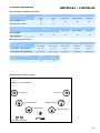
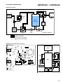
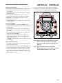
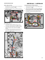
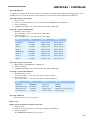
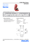
Senseo® Latte Duo HD7855/60 HD7856/60 Philips Consumer Lifestyle Service Manual PRODUCT INFORMATION Safety • This product meets the requirements regarding interference suppression on radio and TV. • After the product has been repaired, it should function properly and has to meet the safety requirements as officially laid down at this moment. TECHNICAL INFORMATION • Voltage : • Frequency : • Power consumption : Boiler : º : º Thermo block • Color setting : • Dimensions (WxDxH) º Appliance º F-Box • Materials º Housing º Spout, collector º Water container º Drip tray • Stand-by power consumption • Brewing pressure • Steam pressure • Water container capacity • Auto shut-off time • Volumes and recipes, see table: Published by Philips Consumer Lifestyle 13/10 Printed in the Netherlands © Copyright reserved 220 - 240 V 50 Hz 2450 W 1450 W 1200 W Deep Black & Misty Dawn : 210 x 315 x 290 mm : 285 x 390 x 334 mm : : : : : : : : : PA, PP, ABS PP PP ABS 0,5 W 1,6 Bar 1,0 Bar 1,0 L 15 min Subject to modification HD7855/60 / HD7856/60 TECHNICAL INFORMATION General Coffee and Milk specifications: Black coffee Milk recipe In-cup volume (in mL) Regular Strong General WEU version 122 60 France specific version 100 60 Cappuccino Latte Macchiato Café Latte 160 220 190 Milk recipe Temperature indication (in °C) Black coffee General WEU 74 Cappuccino Latte Macchiato Café Latte 69 63 67 72 France Specific Measurement specifications: Black coffee Water spec (without pod, in mL) Milk recipe General WEU France Specific Coffee (water) Milk (water) Total (water) 133 ± 10 111 ± 10 72 ± 10 68 ± 10 140 ± 10 2-cups (with 2-cups podholder) 2 x 133 ± 10 2 x 111 ± 10 2 x 72 ± 10 2 x 68 ± 10 2 x 140 ± 10 Temperature indication water (in °C) General WEU France Specific 74 72 1-cup (with 1-cup podholder) Capacitive User interface layout CALC Calc LED & Button Milk only 6. 1. Café Latte 2. Latte Macchiato Strong Coffee 5. 3. Cappuccino 4. Normal Coffee AUTO OFF 1-cup LED 2-cup LED 2-24 HD7855/60 / HD7856/60 TECHNICAL INFORMATION Hydraulic flowchart n Three-way valve m p jj Steam connector g l o Venting valve hh f ii Water Container gg ff e d k Thermo dd block cc i j aa bb Steam pump Overpressure valve a-p aa - jj Brew head Boiler ee Legend: h a b c Water pump Inside the appliance Low pressure tube High pressure tube Low pressure connections High pressure connections PCBA layout and functional schematic AMP3 UI PCBA J2 Black wire AMP7 Boiler Yellow wire AMP2 Blue wire TCO AMP4 Fuse White wire Pump P NTC -t Fuse NTC-B NTC-TB J7 Water level J4 J6 AMP6 J5 Steam pump P WSS PCBA Fuse J3 - UI Brewhead switch NTC L AMP10 -t Fuse Brown wire N Brown wire AMP1 Brown wire from cordset Red wire AMP9 Thermoblock AMP8 AMP5 Brewhead sensor Brown wire Brown wire Water level sensor E 3-24 TECHNICAL INFORMATION HD7855/60 / HD7856/60 Tools Tools required for repair and diagnostics are: • Flathead screwdriver # 0, # 2 • Torx screwdriver (T15) • Cutter • Cable tie tightening tool • Digital Multimeter º Fluke 116 or comparable device with a base accuracy for temperature of 0,05 % or ± 0,3 °C Temperature probe 80PK-22 (80AK-A Thermocouple adapter required) • Scale º KERN EMB 500-1 or comparable device with a base accuracy of 0,05 % or ± 0,5 g • Power meter º Voltcraft EnergyCheck 3000 or comparable device with a base accuracy of 1 % or ± 5W • Stopwatch º Basic model Note: All measurement devices need to be calibrated, certified and traceable to the international standards/laboratories. 4-24 DISASSEMBLY- AND RE-ASSEMBLY ADVISE Remove all loose parts like Driptray, water container and pod-holders. Remove the back cover. • Remove the four Torx screws (A) (T15) from the back cover. • Carefully unhook the back cover from behind the both side covers. • Use a flathead screwdriver to undo both snap hooks on either side of the back cover • The back cover can now be tilted forward. • Two hoses are still connected to the water container socket, they can be removed for easy access. Remove the front cover. • Place the appliance on its backside, to be able to reach the underside. • Use a flathead screwdriver to undo both snap hooks. 2 HD7855/60 / HD7856/60 Remove the side covers. • To be able to remove the side covers the top cover surrounding the lid needs to be removed, to do this two snap hooks need to be undone, they can be reached via the opening of the back cover. • Unlatching the hooks needs some force, once undone you need to open the brewchamber to be able to completely remove the top cover. • Unscrew both screws (B) on top side of the appliance, they were previously covered by the top cover. • Place the appliance on its backside, now you can undo the snap hooks (two on either side) , then you can remove the side panels. 1 With all covers removed you are able to reach all main components: - Pump - Boiler - Steam pump - 3-way valve - Thermo block fuses - Brew head 5-24 DISASSEMBLY- AND RE-ASSEMBLY ADVISE Remove the brewhead. • Unhook the 3-way valve from the Brew chamber back frame and undo the hose from the 3-way valve to the brew chamber. • Unhook the boiler from the boiler support on the Brew chamber bottom. • Unhook the Brewhead detection sensor from its mounting and disconnect the UI cable from the Main PCBA (J3) to the brewhead, and undo its routing through the inner frame. • The Brew head can now be tilted forward and removed from the appliance. Remove the PCBA • To be able to remove or replace the PCBA it is the easiest to open the appliance up until you have the Brew head removed. • Carefully unplug all connectors on the lower right side of the PCBA for the NTC’s, Brew head switch and water level sensor. • Disconnect the Brown and Blue lead from the Cordset on the left side of the PCBA • Undo all fixed leads from their routing through the frame. They are going to: Boiler, Thermo block, Steam pump and Water pump. • The PCBA is held in place by one screw (E) in the center of the PCBA. Open the brew head lid • To be able to open the lid of the brew head, remove the front, back and side covers. • Disconnect the UI cable from the Main PCBA (J3) to the brewhead, and undo its routing through the inner frame. • Undo the hose from the 3-way valve to the brew head. • Use a flathead screwdriver to unhook one side of the hinges of the brew head lid. Carefully feed the hose and cable through the frame. HD7855/60 / HD7856/60 • To open the lid, undo the eight snaphooks holding the lid in place. To be able to remove the lid completely the lever needs to be in the Open position (flipped up). Note: Please make very sure that all wires you have undone will be put back properly and with the same routing as they have originally been designed. Note: Any tie-wrap that has been cut must be replaced by a new one as specified on the Parts list, and tightened with a force of 115 N. 6-24 HD7855/60 / HD7856/60 REPAIR INSTRUCTION Boiler / Brew chamber 1. Brewhead sensor wire must be taped as far away from the boiler wires as possible. (EMC) 2. Boiler wires over the boiler, not behind or in front of the boiler. (Safety) 1 Cordset, Earthwire and Thermoblock 1. Ferrite bead must be in place and ty-wrapped to filter out interference. (EMC) 2. “Clean” Brown and Blue wire must be ty-wrapped to Earth-wire close the Thermo-block. Earth-wire must be as far away from the cord-set as possible. (EMC) 3. Two Black fuse-wires to Thermo-block must run horizontal to the right, running behind the Steampump. (Safety) 3 2 1 2 PCBA – Ty wraps After PCBA replacement: 1. Ty-wrap Black,Yellow and White lead close to the connection of the white lead on the PCBA. (Safety) 2. Ty-wrap Black,Yellow, White, Blue and Red lead close to the connection of the red lead on the PCBA. (Safety) 3. Ty-wrap Black,Yellow, White, Blue, Red and 4x brown close to the connection of the lowest two brown wires on the PCBA. (Safety) 1 2 3 7-24 REPAIR INSTRUCTION Descaling Scale builds up inside the machine during use. It is essential to descale the SENSEO® coffee machine when the CALC light goes on. If the descaling procedure is not performed correctly, scale residue remains behind in the machine. This causes scale to build up more quickly and may cause permanent and irreparable damage to the machine. Use the correct descaling agent Use SENSEO® Descaler (HD7012, HD7011, HD7006) only. It has been developed to ensure better machine performance and operation. Never use a descaling agent base on mineral acids such as Sulphuric acid, Acetic acid (vinegar) or Hydrochloric acid. These descaling agents may damage your SENSEO® coffee machine. For detailed instructions please refer to the Directions for Use, Chapter Descaling. HD7855/60 / HD7856/60 Volume adjustment Note: Volume adjustment may only be carried out in case the repair technician is sure there is no other underlying cause (e.g. leakage, incorrect voltage settings etc.) for the deviation in volume from the factory default. How to adjust the volume output: 1. Make sure the boiler is filled properly, otherwise perform the Flush before first use procedure, according to the instructions in the DFU 2. Switch the appliance on, and wait until the unit is ready. 3. Place either the 1-cup or the 2-cup pod holder in the appliance without a coffee pod. 4. Calibrate a scale with the cup you are going to use for the measurement. 5. Press the Normal coffee button once, to make a normal cup of water. (when finished also poor the contents of water left in the pod holder into the cup) 6. Measure the output and compare to the specifications on Page 2. 7. Determine the deviation from the specification, the deviation can be adjusted in steps of 3,5 mL. The deviation divided by 3,5 will tell you how many steps you need to in-, or decrease. 8. Follow the steps as mentioned under Service modes Manual pump calibration to re-calibrate the pump. 9. Measure the newly programmed volume. 8-24 REPAIR INSTRUCTION HD7855/60 / HD7856/60 Service modes The appliance is equipped with a dedicated service mode. The service mode enables you to carry out some settings and tests. Please note, as the appliance is equipped with a capacitive touch panel as a user interface, special attention is required to be able to enter several service modes. The capacitive buttons need 0,5 seconds to initialize after the mains is connected. During this timeslot the capacitive buttons must not be touched, otherwise you will not be able to enter the service modes. • Manual pump calibration Calibration-step 0: Entry to calibration mode 1. Connect mains; 2. After 0.5 second and before 1.5 second operate Button 2 and Button 5 simultaneously. On/off LED will be switched ON. 3. Release all switches. On/Off LED will be switched OFF. Calibration-step 1A: Decrease calibration value 1. Push (and release) button 2 to decrease the calibration value. The On/Off LED will be ON for 0.5 seconds. 2. Repeat step 1A.1 when required. Calibration-step 1B: Increase calibration value 1. Push (and release) button 5 to increase the calibration value. The On/Off LED will be ON for 0.5 seconds. 2. Repeat step 1B.1 when required. Calibration-step 2: Store calibration value 1. Operate the On/Off button. On/Off LED will blink fast for 1.0 seconds and the calibration value is stored. 2. Release all switches The On/Off and 1-cup LED will be OFF Calibration-step 3: End mode 1. Disconnect mains End test program 9-24 HD7855/60 / HD7856/60 REPAIR INSTRUCTION • Sensor & LED test To validate the assembly and electrical correctness of an appliance, especially during testing and debugging phase, a sensor and LED test is very useful. Please keep in mind that it is not an automated test and only intended as indication. Test-step 0: Entry to test mode 1. Connect mains; 2. After 0.5 second and before 1.5 second operate Button 2, On/Off button and Button 5. 3. Release all switches. 4. All LEDs will be ON for 1.0 seconds and after that switch to OFF again. Test-step 1: Button identification 1. Manually operate a button. The related LED - refer to the table below - will be ON. 2. Release the button. The related LED - refer to the table below - will be OFF. Sensor LED LED on LED off Decal button Decal LED Button pressed Button released Button 1 1-cup LED Button pressed Button released Button 2 1-cup LED Button pressed Button released Button 3 1-cup LED Button pressed Button released On/Off button On/Off LED Button pressed Button released Button 4 2-cup LED Button pressed Button released Button 5 2-cup LED Button pressed Button released Button 6 2-cup LED Button pressed Button released Test-step 2: Entry sensor mode 1. Operate Button 2, On/Off button and Button 5. 2. Release all switches 3. All LEDs will be ON for 1.0 seconds and after that switch to OFF again. Test-step 3: Sensor identification 1. Manually operate a sensor. The related indicator - refer to the table below - will be activated. 2. Release the sensor. The related indicator - refer to the table below - will be deactivated. Sensor LED LED on LED off NTC Boiler On/Off LED NTC error NTC OK NTC Thermo block Decal LED NTC error NTC OK Water level sensor 1-cup LED Water present Water low or no water present Brew head sensor 2-cup LED Brew head closed Brew head open Test-step 4: End test 1. Disconnect mains end test program • Boiler reset Boiler reset-step 0: Entry to boiler reset mode 1. Connect mains. 2. After 0.5 second and before 1.5 second operate Button 3 and Button 4. 3. Release all switches The On/Off LED will blink fast for 0.5 second. 10-24 YES SATISFACTION TEST Combined Measurement Appliance is already RESET Flush with 1 pod holder RESET appliance & Flush with 1 pod holder START Appliance OK 2 cups volume (133 ± 10 ml) Difference : Left / Right < 10 ml OK 1 cup volume (133 ± 10 ml) OK First 1 cup temperature with water (> 74 °C) NO LEAKAGE? YES Water out of spout? (within 5 sec?) YES Is pump working? Heating (1400 W) (2650 W for HD785x) YES Appliance does start? ON - time no more than 5 sec NOK NOK NOK YES NO NOK 1 cup volume (133 ± 10 ml) STOP Flushing Check / repair brew head switch OK NO Fast blinking during start ON / OFF switch? YES YES On / Off knob blinks 1 x per second? NO NO YES On / Off knob blinks 5 x per second? No function NO NO Rapid blinking for 1 sec when cable is plugged in? NO YES CHECK LIST Volume too high / too low Difference : Left / Right > 10 ml Check and / or change NTC Temperature OK? CHECK LIST position leakage Check for (Semi) empty Boiler Check on LEAKAGE NOK OK NOK NOK Check Boiler fuses or TCO Check pump NOK NOK Check WC [FLOAT] / HAL sensor Check Cables or change PCBA MAIN FLOW CHART Replace BOILER Replace PUMP Replace PUMP Replace BOILER & PUMP Repair / replace WC [FLOAT] / HAL sensor Exchange the complete appliance REPAIR INSTRUCTION HD7855/60 / HD7856/60 Functional test diagram for milk-based appliances 11-24 HD7855/60 / HD7856/60 REPAIR INSTRUCTION Additional functional test for milk recipe volume and temperature START Appliance Appliance does start? YES YES RESET appliance & Flush with 1 pod holder Heating (2650 W) Is pump working? YES Water out of spout? (within 5 sec?) YES LEAKAGE? NO 1st Cup COFFEE Volume / temperature OK CAPPUCHINO temperature with water (> 62 °C) Combined Measurement OK CAPPUCHINO volume (140 ± 15 ml) (HD7853 & 54) (150 ± 15 ml) (HD7850 & 52) CHECK LIST Volume too high Volume too low Note: For all “action” boxes marked in yellow please refer to the latest version of the Senseo Repair Process. Note: For new repair engineers it is advisable to start with the complete Senseo Repair Process, your contact in the Global Consumer Care organization can provide this to you. 12-24 HD7855/60 / HD7856/60 PARTS LIST Pos Service code Description Remark 1 4222 25956731 Milk Frothing Unit (MFU) assy Chrome / Misty dawn 110 4222 259 56511 MFU spout cover Chrome 120 4222 240 60792 MFU lock 130 4222 247 71392 Setting chamber 140 4222 247 71341 Steam nozzle assy 150 4222 247 71372 Receptor house 160 Star white MFU bottom cover Misty dawn 2 4222 259 60931 Milk hose assy ME Deep black 3 4222 259 44211 Pad holder assy 1-cup 4 4222 259 44221 Pad holder assy 2-cup 5 4222 247 61280 Collector 6 Coffee spout assy Deep black / Misty dawn 610 4222 247 71672 Coffee spout cover Misty dawn 620 4222 247 71662 Coffee spout Deep black 8 4222 247 72061 Drip tray cover Deep black 9 4222 247 71562 Drip tray Deep black 10 4222 259 59051 Water container (WC) assy Sepia grey 1010 Float spring 1020 Float assy 1030 Valve seal 1040 Valve spring 1050 Valve rod 11 4222 247 71543 Top cover Deep black 12 4222 259 56721 Back cover assy Deep black 1210 WC sealing 1220 Filter 1230 WC socket 13 4222 247 59473 Housing Sensor Water level 14 4222 259 56481 Sensor Water level 15 4222 247 71533 Side panel Left Deep black 16 4222 247 71512 Frame Deep black 17 4222 247 71551 Front panel Deep black 18 4222 247 71522 Side panel Right Deep black 19 4222 259 56581 Sensor BC Lid close 20 4222 247 61601 Housing BC Sensor 21 4222 259 57071 Steam outlet assy 2110 4222 247 07941 O-ring 22 4222 247 72163 BC back frame 23 4222 259 59551 3-way valve (3WV) 24 4222 247 71052 PCB cover 25 4222 259 60321 Programmed Brew chamber (BC) assy Deep black Deep black / Misty dawn 13-24 HD7855/60 / HD7856/60 PARTS LIST Pos Service code Description Remark 2510 4222 259 60971 Programmed Top lid assy printed Black 2520 4222 259 60421 Lever assy Deep black / Misty dawn 2530 4222 247 61310 Push rod 2540 Hose 3WV - BC 2550 4222 240 01410 Slider spring 2560 4222 247 71242 Lid frame 2570 4222 240 05990 Ejector pin 2580 4222 247 06810 BC seal 2590 4222 247 41920 Distribution disk 25100 4222 240 01453 Lid spring 25110 BC bottom Misty dawn Black 25120 4222 259 59081 MFU guidance assy 26 4222 247 61940 TCO cap 27 4222 247 43690 Boiler pin cover 28 4222 259 41620 NTC assy 29 Hose B - 3WV 30 4222 259 52091 Boiler v70 31 4222 247 05134 O-ring (NTC) 32 3210 Dark grey Thermoblock assy 4222 259 59231 230 V 230 V 50 Hz Venting valve (VV) 3220 Hose TP - VV 3221 Hose SV - TB 3222 Hose TB - TP 3223 Hose TP - Steam outlet 3230 4222 247 72081 T-piece (TP) 3240 4222 259 41870 Fuse assy welded 1 piece 3250 4222 259 41750 Thermoblock (TB) 230 V 50 Hz 33 3310 Inner frame assy 4222 259 60301 3320 WSS PCB assy HD7855 / 56 Clamp 3330 4222 247 70981 Boiler support 3340 4222 247 07891 Hose WP - B 3341 Hose TP - WC 3342 Hose SV - TP 3343 Hose TP - VV 3344 Hose SP - SV 3345 Hose inlet SP 3346 4222 247 71473 3347 Hose connector WP Hose inlet WP 3350 4222 247 72081 T-piece (TP) 3360 4222 259 41180 Safety valve (SV) assy 14-24 HD7855/60 / HD7856/60 PARTS LIST Pos Service code Description Remark 3370 4222 259 41230 Steam pump (SP) CEME E151 3371 Damper SP 3380 4222 259 56571 Earth wire assy 3390 4222 259 37240 Pump (WP) 3391 4222 247 04992 Damper WP 3392 4222 240 06771 Spring WP 33100 Inner frame WSS 33110 Inner frame WP 34 4222 247 71503 Base plate 35 4213 247 05256 Foot 100 4222 244 50680 Ty-wrap 101 4222 244 50692 Ty-wrap B 230 V 50 Hz Misty dawn 15-24 EXPLODED VIEW HD7855/60 / HD7856/60 110 120 130 1 140 150 160 2 16-24 HD7855/60 / HD7856/60 EXPLODED VIEW 1010 1020 3 10 1030 1040 1050 4 5 610 6 620 8 9 17-24 EXPLODED VIEW HD7855/60 / HD7856/60 11 A 4x 1210 1220 i 12 1230 a 13 14 Q 18-24 EXPLODED VIEW HD7855/60 / HD7856/60 B B 15 16 17 18 19-24 HD7855/60 / HD7856/60 EXPLODED VIEW 22 p 19 20 f 23 g N jj 2110 21 C 24 20-24 HD7855/60 / HD7856/60 EXPLODED VIEW 2510 2520 2530 g 2540 2550 h D 8x M 100 2560 25 2570 2580 2590 25100 2x 25110 25120 21-24 HD7855/60 / HD7856/60 EXPLODED VIEW M J5 OP J3 N Q J4 J6 E J7 W 26 R S T U V 3310 27 3320 f 28 3330 Y 29 e U P 30 31 d 101 3340 c 22-24 HD7855/60 / HD7856/60 EXPLODED VIEW p m 3341 n 3350 l o 3342 3210 ii 3343 k 3360 3220 cc bb 3344 3221 aa 3370 S 3371 j 3345 hh 32 X gg i jj 3230 33 ff 3222 T 3223 3240 2x ee X Y dd 3250 F 3x Z 3380 3346 c O R 3390 3391 a b 3392 3347 23-24 HD7855/60 / HD7856/60 EXPLODED VIEW 33100 H G 33110 G G Z W V 34 35 2x 24-24