1
288BNV EVOLUTIONR V VARIABLE SPEED HEAT PUMP
189BNV EVOLUTIONR V VARIABLE SPEED AIR CONDITIONER
WITH PURONr REFRIGERANT
Service Manual
TABLE OF CONTENTS
PAGE
UNIT IDENTIFICATION . . . . . . . . . . . . . . . . . . . . . . . . . . . . . . . . . . . . . . . . . . . . . . . . . . . . . . . . . . . . . . . . . . . . . . . . . . . . . . . . . 2
REFRIGERANT PIPING LENGTH LIMITATIONS . . . . . . . . . . . . . . . . . . . . . . . . . . . . . . . . . . . . . . . . . . . . . . . . . . . . . . . . . . . 3
LONG LINE APPLICATIONS . . . . . . . . . . . . . . . . . . . . . . . . . . . . . . . . . . . . . . . . . . . . . . . . . . . . . . . . . . . . . . . . . . . . . . . . . . . . . 3
SAFETY CONSIDERATIONS . . . . . . . . . . . . . . . . . . . . . . . . . . . . . . . . . . . . . . . . . . . . . . . . . . . . . . . . . . . . . . . . . . . . . . . . . . . . . 4
GENERAL INFORMATION . . . . . . . . . . . . . . . . . . . . . . . . . . . . . . . . . . . . . . . . . . . . . . . . . . . . . . . . . . . . . . . . . . . . . . . . . . . . . . 4
ELECTRICAL . . . . . . . . . . . . . . . . . . . . . . . . . . . . . . . . . . . . . . . . . . . . . . . . . . . . . . . . . . . . . . . . . . . . . . . . . . . . . . . . . . . . . . . . . . 5
MAJOR COMPONENTS . . . . . . . . . . . . . . . . . . . . . . . . . . . . . . . . . . . . . . . . . . . . . . . . . . . . . . . . . . . . . . . . . . . . . . . . . . . . . . . 5--7
AOC Board . . . . . . . . . . . . . . . . . . . . . . . . . . . . . . . . . . . . . . . . . . . . . . . . . . . . . . . . . . . . . . . . . . . . . . . . . . . . . . . . . . . . . . . . . . 5
Inverter . . . . . . . . . . . . . . . . . . . . . . . . . . . . . . . . . . . . . . . . . . . . . . . . . . . . . . . . . . . . . . . . . . . . . . . . . . . . . . . . . . . . . . . . . . . . . . 5
Variable Speed Compressor . . . . . . . . . . . . . . . . . . . . . . . . . . . . . . . . . . . . . . . . . . . . . . . . . . . . . . . . . . . . . . . . . . . . . . . . . . . . . . 5
Electronic Expansion Valve (EXP) . . . . . . . . . . . . . . . . . . . . . . . . . . . . . . . . . . . . . . . . . . . . . . . . . . . . . . . . . . . . . . . . . . . . . . . . . 6
Outdoor Fan Motor . . . . . . . . . . . . . . . . . . . . . . . . . . . . . . . . . . . . . . . . . . . . . . . . . . . . . . . . . . . . . . . . . . . . . . . . . . . . . . . . . . . . . 6
Pressure Transducer (SPT) . . . . . . . . . . . . . . . . . . . . . . . . . . . . . . . . . . . . . . . . . . . . . . . . . . . . . . . . . . . . . . . . . . . . . . . . . . . . . . . 6
Pressure Equalizer Valve (PEV) . . . . . . . . . . . . . . . . . . . . . . . . . . . . . . . . . . . . . . . . . . . . . . . . . . . . . . . . . . . . . . . . . . . . . . . . . . . 6
Outdoor Coil Thermistor (OCT) . . . . . . . . . . . . . . . . . . . . . . . . . . . . . . . . . . . . . . . . . . . . . . . . . . . . . . . . . . . . . . . . . . . . . . . . . . . 6
Suction Thermistor (OST) . . . . . . . . . . . . . . . . . . . . . . . . . . . . . . . . . . . . . . . . . . . . . . . . . . . . . . . . . . . . . . . . . . . . . . . . . . . . . . . 7
Discharge Thermistor (ODT) . . . . . . . . . . . . . . . . . . . . . . . . . . . . . . . . . . . . . . . . . . . . . . . . . . . . . . . . . . . . . . . . . . . . . . . . . . . . . 7
Crankcase Heater . . . . . . . . . . . . . . . . . . . . . . . . . . . . . . . . . . . . . . . . . . . . . . . . . . . . . . . . . . . . . . . . . . . . . . . . . . . . . . . . . . . . . . 7
Time--Delays . . . . . . . . . . . . . . . . . . . . . . . . . . . . . . . . . . . . . . . . . . . . . . . . . . . . . . . . . . . . . . . . . . . . . . . . . . . . . . . . . . . . . . . . . 7
COMMUNICATION AND STATUS FUNCTION LIGHTS . . . . . . . . . . . . . . . . . . . . . . . . . . . . . . . . . . . . . . . . . . . . . . . . . . . . . 7
CHECK CHARGE . . . . . . . . . . . . . . . . . . . . . . . . . . . . . . . . . . . . . . . . . . . . . . . . . . . . . . . . . . . . . . . . . . . . . . . . . . . . . . . . . . . . . . . 9
TROUBLESHOOTING . . . . . . . . . . . . . . . . . . . . . . . . . . . . . . . . . . . . . . . . . . . . . . . . . . . . . . . . . . . . . . . . . . . . . . . . . . . . . . . . 9--13
Service Tool . . . . . . . . . . . . . . . . . . . . . . . . . . . . . . . . . . . . . . . . . . . . . . . . . . . . . . . . . . . . . . . . . . . . . . . . . . . . . . . . . . . . . . 14--30
System Communication Failure . . . . . . . . . . . . . . . . . . . . . . . . . . . . . . . . . . . . . . . . . . . . . . . . . . . . . . . . . . . . . . . . . . . . . . . . . . 14
Model Plug . . . . . . . . . . . . . . . . . . . . . . . . . . . . . . . . . . . . . . . . . . . . . . . . . . . . . . . . . . . . . . . . . . . . . . . . . . . . . . . . . . . . . . . . . . 14
Status Codes . . . . . . . . . . . . . . . . . . . . . . . . . . . . . . . . . . . . . . . . . . . . . . . . . . . . . . . . . . . . . . . . . . . . . . . . . . . . . . . . . . . . . . . . . 14
Variable Speed Compressor Winding Resistance . . . . . . . . . . . . . . . . . . . . . . . . . . . . . . . . . . . . . . . . . . . . . . . . . . . . . . . . . . . . . 14
Fan Motor . . . . . . . . . . . . . . . . . . . . . . . . . . . . . . . . . . . . . . . . . . . . . . . . . . . . . . . . . . . . . . . . . . . . . . . . . . . . . . . . . . . . . . . . . . . 15
Control Fault . . . . . . . . . . . . . . . . . . . . . . . . . . . . . . . . . . . . . . . . . . . . . . . . . . . . . . . . . . . . . . . . . . . . . . . . . . . . . . . . . . . . . . . . 15
Brown Out Protection . . . . . . . . . . . . . . . . . . . . . . . . . . . . . . . . . . . . . . . . . . . . . . . . . . . . . . . . . . . . . . . . . . . . . . . . . . . . . . . . . . 15
230v Line (Power Disconnect) Detection . . . . . . . . . . . . . . . . . . . . . . . . . . . . . . . . . . . . . . . . . . . . . . . . . . . . . . . . . . . . . . . . . . . 15
Pressure Switch Protection . . . . . . . . . . . . . . . . . . . . . . . . . . . . . . . . . . . . . . . . . . . . . . . . . . . . . . . . . . . . . . . . . . . . . . . . . . . . . . 15
Temperature Thermistors . . . . . . . . . . . . . . . . . . . . . . . . . . . . . . . . . . . . . . . . . . . . . . . . . . . . . . . . . . . . . . . . . . . . . . . . . . . . . . . 16
Fault Code Action Table . . . . . . . . . . . . . . . . . . . . . . . . . . . . . . . . . . . . . . . . . . . . . . . . . . . . . . . . . . . . . . . . . . . . . . . . . . . . . . . . 18
Variable Speed Drive LED Location and Description . . . . . . . . . . . . . . . . . . . . . . . . . . . . . . . . . . . . . . . . . . . . . . . . . . . . . . . . . . 23
Compressor Power Harness Assembly Replacement . . . . . . . . . . . . . . . . . . . . . . . . . . . . . . . . . . . . . . . . . . . . . . . . . . . . . . . . . . 25
Inverter Assembly with Shield Gasket Installation . . . . . . . . . . . . . . . . . . . . . . . . . . . . . . . . . . . . . . . . . . . . . . . . . . . . . . . . . . . . 27
Compressor Replacement . . . . . . . . . . . . . . . . . . . . . . . . . . . . . . . . . . . . . . . . . . . . . . . . . . . . . . . . . . . . . . . . . . . . . . . . . . . . . . . 30
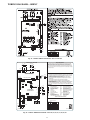
WIRING DIAGRAMS . . . . . . . . . . . . . . . . . . . . . . . . . . . . . . . . . . . . . . . . . . . . . . . . . . . . . . . . . . . . . . . . . . . . . . . . . . . . . . . . . 33--34
REFRIGERATION SYSTEM . . . . . . . . . . . . . . . . . . . . . . . . . . . . . . . . . . . . . . . . . . . . . . . . . . . . . . . . . . . . . . . . . . . . . . . . . . 35--39
Refrigerant . . . . . . . . . . . . . . . . . . . . . . . . . . . . . . . . . . . . . . . . . . . . . . . . . . . . . . . . . . . . . . . . . . . . . . . . . . . . . . . . . . . . . . . . . . 35
Compressor Oil . . . . . . . . . . . . . . . . . . . . . . . . . . . . . . . . . . . . . . . . . . . . . . . . . . . . . . . . . . . . . . . . . . . . . . . . . . . . . . . . . . . . . . . 35
Servicing Systems on Roofs With Synthetic Materials . . . . . . . . . . . . . . . . . . . . . . . . . . . . . . . . . . . . . . . . . . . . . . . . . . . . . . . . . 35
Brazing . . . . . . . . . . . . . . . . . . . . . . . . . . . . . . . . . . . . . . . . . . . . . . . . . . . . . . . . . . . . . . . . . . . . . . . . . . . . . . . . . . . . . . . . . . . . . 35
Service Valves and Pump down . . . . . . . . . . . . . . . . . . . . . . . . . . . . . . . . . . . . . . . . . . . . . . . . . . . . . . . . . . . . . . . . . . . . . . . . . . 35
Liquid Line Filter Drier . . . . . . . . . . . . . . . . . . . . . . . . . . . . . . . . . . . . . . . . . . . . . . . . . . . . . . . . . . . . . . . . . . . . . . . . . . . . . . . . 38
Suction Line Filter Drier . . . . . . . . . . . . . . . . . . . . . . . . . . . . . . . . . . . . . . . . . . . . . . . . . . . . . . . . . . . . . . . . . . . . . . . . . . . . . . . . 38
Thermostatic Expansion Valve (TXV) . . . . . . . . . . . . . . . . . . . . . . . . . . . . . . . . . . . . . . . . . . . . . . . . . . . . . . . . . . . . . . . . . . . . . 38
Accumulator . . . . . . . . . . . . . . . . . . . . . . . . . . . . . . . . . . . . . . . . . . . . . . . . . . . . . . . . . . . . . . . . . . . . . . . . . . . . . . . . . . . . . . . . . 39
REFRIGERATION SYSTEM REPAIR . . . . . . . . . . . . . . . . . . . . . . . . . . . . . . . . . . . . . . . . . . . . . . . . . . . . . . . . . . . . . . . . . . . . . 39
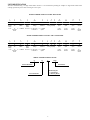
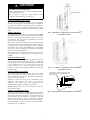
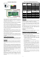
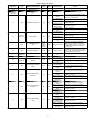
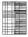
UNIT IDENTIFICATION
The unit is identified using a 16 digit model number structure. It is recommended providing the complete 16 digit model number when
ordering replacement parts to insure receiving the correct parts.
MODEL NUMBER NOMENCLATURE -- HEAT PUMP
1
N
2
N
3
N
4
A
5
A/N
6
N
7
N
8
N
9
N
10
A/N
11
A/N
12
N
14
A
2
8
8
B
N
V
0
3
6
0
0
0
A
Product
Family
2=HP
Tier
SEER
Major
Series
B=Puron
Voltage
Variations
Open
Open
Open
Series
N= 208 ---230 ---1
or 208/230 ---1
V = Variable
Speed
0=Not
Defined
0=Not
Defined
0=Not
Defined
A=
Original
Series
8=
8 = 18 SEER
Evolution
Series
Cooling Capacity
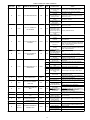
MODEL NUMBER NOMENCLATURE -- AIR CONDITIONER
1
N
2
N
3
N
4
A
5
A/N
6
N
7
N
8
N
9
N
10
A/N
11
A/N
12
N
14
A
1
8
9
B
N
V
0
3
6
0
0
0
A
Product
Family
1=AC
Tier
SEER
Major
Series
B=Puron
Voltage
Variations
Open
Open
Open
Series
N= 208 ---230 ---1
or 208/230 ---1
V = Variable
Speed
0=Not
Defined
0=Not
Defined
0=Not
Defined
A=
Original
Series
8=
9 = 19 SEER
Evolution
Series
Cooling Capacity
SERIAL NUMBER NOMENCLATURE
01
06
E
Week of Manufacture
00001
Serial Number
Manufacturing Site
E = Collierville TN
X = Monterrey Mexico
Year of Manufacture
2
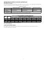
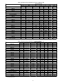
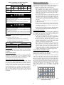
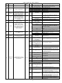
REFRIGERANT PIPING LENGTH LIMITATIONS
Maximum Line Lengths:
The maximum allowable total equivalent length varies depending on the vertical separation. See the tables below for allowable lengths
depending on whether the outdoor unit is on the same level, above or below the outdoor unit.
Maximum Line Lengths
Units on equal level
MAXIMUM ACTUAL LENGTH
ft (m)
100 (30.5)
MAXIMUM EQUIVALENT LENGTH{
ft (m)
100 (30.5)
MAXIMUM VERTICAL SEPARATION ft (m)
N/A
100 (30.5)
100 (30.5)
100 (30.5)
Outdoor unit ABOVE
indoor unit
Outdoor unit BELOW
indoor unit
See Table ’Maximum Total Equivalent Length: Outdoor Unit BELOW Indoor Unit’
{ Total equivalent length accounts for losses due to elbows or fitting. See the Long Line Guideline for details.
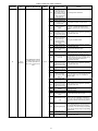
Maximum Total Equivalent Length{ -- Outdoor Unit BELOW Indoor Unit
Size
Liquid Line
Diameter
w/ TXV
1 ---Ton
2 ---Ton
3 ---Ton
4 ---Ton
5 ---Ton
3/8
3/8
3/8
3/8
3/8
0--- 20
(0 --- 6.1)
100*
100*
100*
100*
100*
HP with Puronr Refrigerant --- Maximum Total Equivalent Length{
Vertical Separation ft (m) Outdoor unit BELOW indoor unit;
21--- 30
31--- 40
41--- 50
51--- 60
61--- 70
(6.4 --- 9.1)
(9.4 --- 12.2)
(12.5 --- 15.2)
(15.5 --- 18.3)
(18.6 --- 21.3)
100*
100*
100*
100*
100*
100*
100*
100*
100*
100*
100*
100*
100*
100*
100*
100*
100*
100*
100
100
100*
100*
100*
100
100
71--- 80
(21.6 --- 24.4)
100*
100*
100*
--- ----- ---
* Maximum actual length not to exceed 100 ft (30.5 m)
{ Total equivalent length accounts for losses due to elbows or fitting.
--- --- = outside acceptable range
LONG LINE APPLICATIONS
Unit is approved for up to 100 ft (30.5 m) equivalent length and vertical separations shown above with no additional accessories.
Longer line set applications are not permitted.
3
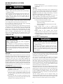
SAFETY CONSIDERATIONS
Installation, service, and repair of these units should be attempted
only by trained service technicians familiar with standard service
instruction and training material.
All equipment should be installed in accordance with accepted
practices and unit Installation Instructions, and in compliance with
all national and local codes. Power should be turned off when
servicing or repairing electrical components. Extreme caution
should be observed when troubleshooting electrical components
with power on. Observe all warning notices posted on equipment
and in instructions or manuals.
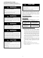
!
WARNING
ELECTRICAL HAZARD -- HIGH VOLTAGE!
Failure to follow this warning could result in personal injury
or death.
Electrical components may hold charge. DO NOT remove
control box cover for 2 minutes after power has been
removed from unit.
PRIOR TO TOUCHING ELECTRICAL COMPONENTS:
Verify zero (0) voltage at inverter connections shown on
inverter cover.
WARNING
!
ELECTRICAL SHOCK HAZARD
Failure to follow this warning could result in personal
injury or death.
Before installing, modifying, or servicing system, main
electrical disconnect switch must be in the OFF position.
There may be more than 1 disconnect switch. Lock out and
tag switch with a suitable warning label.
!
WARNING
EXPLOSION HAZARD
Failure to follow this warning could
result in death, serious personal injury,
and/or property damage.
Never use air or gases containing
oxygen for leak testing or operating
refrigerant compressors. Pressurized
mixtures of air or gases containing
oxygen can lead to an explosion.
!
!
CAUTION
CUT HAZARD
Failure to follow this caution may result in personal injury.
Sheet metal parts may have sharp edges or burrs. Use care and
wear appropriate protective clothing and gloves when
handling parts.
Refrigeration systems contain refrigerant under pressure. Extreme
caution should be observed when handling refrigerants. Wear
safety glasses and gloves to prevent personal injury. During normal
system operations, some components are hot and can cause burns.
Rotating fan blades can cause personal injury. Appropriate safety
considerations are posted throughout this manual where potentially
dangerous techniques are addressed.
If you do not understand any of the warnings, contact your
product distributor for better interpretation of the warnings.
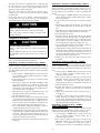
GENERAL INFORMATION
The 288BNV & 189BNV split system heat pump and air
conditioners features a new outdoor cabinet design that uses a
four--sided coil design to minimize the unit footprint and provide
the best heat exchange taking full advantage of the latest variable
speed technology.
The heart of the system is the variable speed rotary compressor
powered through the use of the variable speed drive (VSD) inverter
control. Through the use of Puron refrigerant, compact ECM
outdoor fan motor, VSD and variable speed scroll compressor,
along with the new outdoor cabinet, the unit achieves a Seasonal
Energy Efficiency Ratio (SEER) of up to 19 and up to 11 Heating
Seasonal Performance Factor (HSPF).
To ensure ultimate comfort, these units should be combined with
either the FE fan coil or Variable Speed Gas furnace controlled
with a two wire communication Evolutionr Connext Control
SYSTXBBITC01, SYSTXBBITW01 or SYSTXBBITN01 with
version 11 software or newer. Version 12 software or newer
required for model size 13. This combination will ensure
achievement of comfort with the convenience of fingertip trouble
shooting and diagnostic capability. These units can also use a
standard, 2--stage or single--stage thermostat, for limited
functionality. However, 1--ton models will require the use of an
Evolution Control.
WARNING
UNIT OPERATION AND SAFETY HAZARD
Failure to follow this warning could result in personal
injury or equipment damage.
Puronr (R--410A) systems operate at higher pressures than
standard R--22 systems. Do not use R--22 service equipment
or components on Puronr equipment. Ensure service
equipment is rated for Puronr.
4
ELECTRICAL
!
WARNING
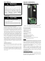
MAJOR COMPONENTS
Application Operational Control Board (AOC)
ELECTRICAL SHOCK HAZARD
Failure to follow this warning could result in personal injury
or death.
Exercise extreme caution when working on any electrical
components. Shut off all power to system prior to
troubleshooting. Some troubleshooting techniques require
power to remain on. In these instances, exercise extreme
caution to avoid danger of electrical shock. ONLY TRAINED
SERVICE
PERSONNEL
SHOULD
PERFORM
ELECTRICAL TROUBLESHOOTING.
Aluminum Wire
!
CAUTION
UNIT OPERATION AND SAFETY HAZARD
Failure to follow this caution may result in equipment
damage or improper operation.
Aluminum wire may be used in the branch circuit (such as
the circuit between the main and unit disconnect), but only
copper wire may be used between the unit disconnect and the
unit.
Whenever aluminum wire is used in branch circuit wiring with this
unit, adhere to the following recommendations.
Connections must be made in accordance with the National
Electrical Code (NEC), using connectors approved for aluminum
wire. The connectors must be UL approved (marked Al/Cu with
the UL symbol) for the application and wire size. The wire size
selected must have a current capacity not less than that of the
copper wire specified, and must not create a voltage drop between
service panel and unit in excess of 2 of unit rated voltage. To
prepare wire before installing connector, all aluminum wire must
be “brush--scratched” and coated with a corrosion inhibitor such as
Pentrox A. When it is suspected that connection will be exposed to
moisture, it is very important to cover entire connection completely
to prevent an electrochemical action that will cause connection to
fail very quickly. Do not reduce effective size of wire, such as
cutting off strands so that wire will fit a connector. Proper size
connectors should be used. Check all factory and field electrical
connections for tightness. This should also be done after unit has
reached operating temperatures, especially if aluminum conductors
are used.
Unit Electrical Power
Power wires from the unit’s disconnect should be routed through
the power wiring hole provided at the bottom of the unit’s control
box.
Connect the ground wire to the ground connection in the control
box and connect the power wiring to the terminal block as shown
on the wiring and Installation Instructions supplied with the unit.
The unit does not require a contactor or outdoor unit transformer in
order to operate.
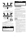
A13361
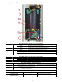
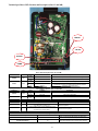
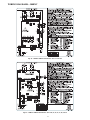
Fig. 1 – AOC (Application Operational Control) Board
The AOC board is located in the lower right hand side of inverter
tray. It’s functions include:
S Compressor speed control
S Outdoor fan motor control
S Reversing valve operation
S Defrost operation
S Crankcase heater operation
S Pressure switch monitoring
S Time Delays
S Pressure Transducer measurements
S PEV control (pressure equalizer valve)
S Temperature measurements
S EXV (Electronic Expansion Valve) operation control
S Inverter communication and control
Inverter
The inverter is located inside the control box. This is an air--cooled
device that communicates with the control board and drives the
compressor and fan motor to the demanded RPM. The inverter is
always powered with line voltage since no contactor is used. The
inverter changes the line voltage to DC volts and then recreates 3
phase sine waves that vary in frequency to drive the compressor
and fan motor at the desired RPM.
NOTE: The unit may be operated with an Evolution Connex
Control or a standard 2--stage HP thermostat. However, 1--ton
models will require the use of an Evolution Control. Evolution
Connex Control will utilize 5 stages of heating and cooling, while
2--stage HP thermostat will only allow 2 discrete stages of heating
and cooling operation.
Variable Speed Compressor
This unit contains a variable speed rotary compressor that has a
wide operating range. It operates on a variable 3 phase sine wave
provided by the inverter. This compressor can only be operated by
the specific inverter supplied with the unit.
5
!
CAUTION
EQUIPMENT DAMAGE HAZARD
Failure to follow this caution may result in equipment damage
and/or improper operation.
Do not attempt to apply line voltage directly to the
compressor. This will destroy the compressor.
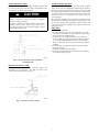
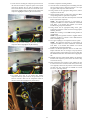
Electronic Expansion Valve (EXV)
This unit uses an electronic expansion valve for refrigerant
metering in the heating mode. The control board drives the EXV to
its proper position based on the operating mode and conditions.
The Evolution Connex Control Service mode allows for manual
opening and closing of the EXV for troubleshooting and pump
down.
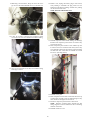
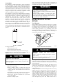
A14302
Outdoor Fan Motor
Fig. 2 – HP Outdoor Coil Thermistor (OCT) Attachment
(On Distributor Tube)
The compact ECM outdoor fan motor is a variable--speed brushless
DC (BLDC) motor that operates at speeds from 400 to 1050 RPM.
The motor is a 3--phase permanent magnet--type motor. Just like
the compressor, this motor speed is determined by the inverter
output frequency and amplitude.
Motor speed is controlled through the inverter board in the outdoor
unit and no electronic module is attached. Motor speed is slowed as
the building load decreases, maintaining the proper condensing
temperature for both cooling and dehumidification. As the building
load increases, the motor will increase speed until it is at maximum
speed at the maximum building load.
At unit start--up, there is a slight delay and thrust motion of the fan
motor/blade in the reverse direction, prior to ramping--up the fan
assembly.
Pressure Transducer (SPT)
A 5 VDC output low pressure transducer that provides a 0--5 VDC
data for interpretation by the control board for a 0 to 200 psig
range of pressure at the suction tube. This interpreted pressure data
is then intelligently used by the AOC control board for low
pressure cut--out, loss of charge management, compressor
protection, oil circulation management, lubrication management
and EXV control.
A14328
Fig. 3 – AC Outdoor Coil Thermistor (OCT) Attachment
(On Distributor Tube)
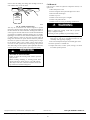
Pressure Equalizer Valve (PEV)
OAT Thermistor must be locked in place with
spherical nib end facing towards the front of
the control box
At the end of every compressor operation (after the 3.5 minute
Time Guard period), the equalizer valve opens for 150 seconds
plus an additional 15 seconds of protection before allowing the
compressor to start ramping up.
The PEV is located next to the suction and discharge of the
compressor. The function of this valve is to prevent the
compressor from starting with a high refrigerant pressure
differential, thus helping the reliability of the compressor.
NOTE: A hissing sound may be heard during the equalization
process. This is normal.
Outdoor Coil Thermistor (OCT)
The outdoor coil thermistor is a 10Kohm resistor used for multiple
system operations. It provides the coil/liquid line temperature to
the heat pump board and user interface. Low ambient operation,
defrost initiation, defrost termination and assistance with OAT
temperature measurement of some of the functions (see Fig.4) .
The sensor must be securely mounted to the tube connecting the
EXV and distributor. See Fig. 2 and Fig. 3 for proper placement.
See Table 5 for proper resistances.
A11142
Fig. 4 – OAT Thermistor Location (Bottom of Control Box)
6
Suction Thermistor (OST)
Crankcase Heater Operation
Suction Thermistor is used for assisting in EXV control and must
be secured on the suction tube and aligned longitudinally to the
vertical surface of the tube axis (see Fig. 5).
This unit has an internal crankcase heater that will be energized
during the off cycle and is intelligently demanded by the system to
prevent the compressor from being the coldest part of the system
thus enhancing the reliability. The crankcase heater will function
as needed any time the outdoor unit is powered. The indoor unit
and UI do not need to be installed for the crankcase heater to
operate properly.
The compressor windings will occasionally be energized during
the OFF cycle (depending on the length of the OFF cycle) to start
the stator heat operation, thus maintaining a sump temperature that
is essential for compressor reliability. The compressor will not run
during this process.
!
CAUTION
UNIT DAMAGE HAZARD
Failure to follow this caution may result in equipment
damage or improper operation.
In order to minimize the ambient influence, make sure the
thermistor curved surface hugs the pipe surface and is
secured tight using the wire tie fished through the original
slot insulating polymer body.
Time Delays
The unit time delays include:
S 3.5 minute time delay after last cycle, initial power up, return
from brown--out condition. To bypass this feature, momentarily
short and release Forced Defrost pins.
S At the end of every compressor ON cycle, there will be 150
seconds of PEV open period for pressure equalization followed
by 15 seconds of PEV Off period before the next compressor
ON cycle. This delay cannot be bypassed as it helps compressor
reliability.
S 15 second delay at termination of defrost before the auxiliary
heat is de--energized.
S See Table 6 for other delay information.
S 10 minute sump warm--up delay. This delay is at the beginning
of each high voltage power up.
A14023
Fig. 5 – Suction Thermistor (OST) Attachment
(On Suction Tube)
Discharge Thermistor (ODT)
Discharge Thermistor is used for protection against over
temperature of the compressor. The ODT is located on the
compressor discharge stub--out (see Fig. 6).
A14024
Fig. 6 – Discharge Thermistor (ODT)
7
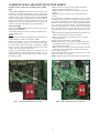
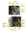
COMMUNICATION AND STATUS FUNCTION LIGHTS
Evolution Connex Control, Green Communications (COMM)
Light
A green LED (COMM light) on the outdoor board (see Fig. 7 and
8) indicates successful communication with the other system
products. The green LED will remain OFF until communication is
established. Once a valid command is received, the green LED will
turn ON continuously. If no communication is received within 2
minutes, the LED will be turned OFF until the next valid
communication. The green LED will be turned off when using a
standard 2--stage non--communicating heat pump thermostat.
Amber Status Light
Amber colored STATUS light indicates operation and error status.
See Table 6 for definitions.
S Two minute time delay to return to standby operation from last
valid communication.
Defrost
This user interface (UI) offers 4 possible defrost interval times: 30,
60 and 90 minutes, or AUTO. The default is AUTO.
Defrost interval times: 30, 60, and 90 minutes or AUTO are
selected by the Evolution Connex Control User Interface if using
UI. The 90 minute selection will default to 60 minutes at ambient
below 37 degrees. The UI setting will supersede the dip switch
settings on the control board if not the same.
If using non--communicating thermostat, defrost intervals are set
using dip switches on outdoor control board (see Fig. 7 and 8).
AUTO defrosts adjusts the defrost interval time based on the last
defrost time as follows:
Fig. 7 – AOC Control Board for 1 and 2 Ton
S When defrost time <5 minutes, the next defrost interval=90
minutes. (outdoor temperature above 37_F)
S When defrost time 5--7 minutes, the next defrost interval=60
minutes.
S When defrost time >7 minutes, the next defrost interval=30
minutes.
The control board accumulates compressor run time. As the
accumulated run time approaches the selected defrost interval time,
the control board monitors the coil temperature sensor for a defrost
demand. If a defrost demand exists, a defrost cycle will be initiated
at the end of the selected time interval. A defrost demand exists
when the coil temperature is at or below 32_F (0_C) for 4 minutes
during the interval. If the coil temperature does not reach 32_F
(0_C) within the interval, the interval timer will be reset and start
over.
S Upon initial power up the first defrost interval is defaulted to 30
minutes. Remaining intervals are at selected times.
S Defrost is only allowed to occur below 50_F (10_C) outdoor
ambient temperature.
The defrost cycle is terminated as described below.
S When OAT is > 25_F (+3.89_C), defrost terminates if outdoor
coil temperature (OCT) > 60_F (+15.6_C). And a minimum of
one (1) minute defrost length.
S When OAT ≦ 25_F (+3.89_C), defrost will terminate if OCT is
>45_F (+4.4_C) and a minimum of 2 minutes defrost length.
S Or 10 minutes has passed.
At the defrost termination, the outdoor fan will turn on 10 seconds
before the reversing valve switching.
NOTE: Compressor speed during defrost will go to defrost speed.
A150034
Fig. 8 – AOC Control Board for 3, 4 and 5 Ton
8
A14021
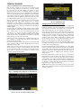
CHECK CHARGE
Charge in CHARGING mode (communicating only)
Unit is factory charged for 15ft (4.57 m) of lineset. If any
refrigerant charge adjustment is required due to the user inputted
line set length, the UI will calculate and display the target
subcooling and the amount of additional charge to be added.
Therefore, the UI is your source of information for charging the
system correctly. Refrigerant charge adjustment amount for adding
or removing 0.6 oz/ft (17.74 g/m) of 3/8 liquid line above or below
15ft (4.57 m) respectively. Perform a final charge check only when
in cooling and OD is between 65_F (18_C) and 100_F (38_C).
The use of a commercial charge metering device (restrictor) such as
Imperial liquid low side charger model 535--C or Watsco
ChargeFaster model CH200 is recommended when adding
refrigerant to an operating system. This prevents potential damage
of liquid slugging of the compressor and allows the subcooling to
stabilize quicker.
Charging using the subcooling method optimizes charge volume
and is preferred if possible. If the outdoor temperature is between
65_F -- 100_F (18.3_C -- 37.8_C) and indoor temperature is 70_F
-- 80_F (21.1_C -- 26.7_C), the option to further adjust charge
using “service valve subcool” will be available in the “charging
mode selection” screen. If temperatures are outside of range, this
option will be greyed out and not selectable.
Initial start--up can be performed using calculated charge only and
once conditions are within range, the ”Service Valve Subcool”
option will become selectable.
Once start is selected the system will operate in a preset mode until
“done” is selected. Wait for required stabilization time then check
subcooling at service valve.
Adjust charge as required to meet target service valve subcooling
shown on screen +/--1 degree. If any adjustment is necessary, add
or remove the charge slowly (no greater than .5 lb per minute) and
allow system to operate for 25 minutes to stabilize, before
declaring a properly charged system.
Fig. 11 – Stabilization Time
Charging Non-- Communicating Systems
Charging Procedure: Force system to operate in high stage
cooling by creating a large differential between room temperature
and set point on thermostat. Use multi--meter to verify that 24
VAC is present between C, Y1 /Y2 terminals at outdoor unit.
Factory charge amount is shown on unit rating plate for high stage.
Target subcooling chart is provided on back of control box door
see Fig. 12 -- 26 for example. To properly check or adjust charge,
condition must be favorable for subcooling charging. Favorable
conditions exists when outdoor temperature is between 65_F
(18_C) and 100_F (38_C), and the indoor temperature is between
70_F (21_C) and 80_F (27_C). Follow the procedure below:
Unit is factory charged for 15ft (4.57 m) of lineset. Adjust charge
by adding or removing 0.6 oz/ft (17.7 g/m) of 3/8 liquid line above
or below 15ft (4.57 m) respectively.
For standard refrigerant line lengths (80ft/24.4 m or less), allow
system to operate in cooling mode at least 25 minutes. If conditions
are favorable, check system charge by subcooling method. If any
adjustment is necessary, adjust charge slowly and allow system to
operate for 25 minutes to stabilize before declaring a properly
charged system.
If the indoor temperature is below 70°F (21.11°C), or the outdoor
temperature is not in the favorable range, adjust charge for line set
length above or below 15ft (4.57 m) and indoor fan coil /furnace
coil per Table 1 and 2. Charge level should then be appropriate for
the system to achieve rated capacity. The charge level should then
be checked at another time when the both indoor and outdoor
temperatures are in a more favorable range.
NOTE: If the line length is beyond 80ft (24.38 m) or greater than
20ft (6.10 m) vertical separation see Long line guideline for special
charging requirement.
A14573
Fig. 9 – Adjusting Charge Using Service Valve Subcool
Fig. 10 – Service Valve Subcool Target Value
A14575
A14574
9
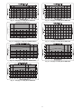
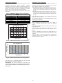
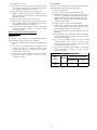
Table 1—Required Charge Adjustment for Indoor Coil Model -- HP
Outdoor Model Size
Furnace or Fan Coil Model Number
/
---
13
24B
240
36
37
48
60
CNPV*18**
---
/
/
/
/
/
/
CAP**18**
---
/
/
/
/
/
/
CNP**24
---
/
/
/
/
/
/
CNPV*19**
---
/
/
/
/
/
/
CAP**24
---
/
/
/
/
/
/
CSPH*24
---
/
/
/
/
/
/
CSPH*30**
/
/
/
/
/
/
/
F(E,V)4(A,B,C)NF002
+0.19
---
---
---
---
/
/
CAP**30
/
---
/
/
/
/
/
CNP**30
/
---
/
/
/
/
/
CNP**36
/
---
---
---
---
/
/
F(E,V)4(A,B,C)N(B,F)003
/
---
---
---
---
/
/
CAP**36
/
---
---
---
---
/
/
CNP**42
/
+.50
---
---
+.75
/
/
CAP**42
/
+.50
---
---
+.75
/
/
CSPH*36
/
/
---
---
+.75
/
/
CSPH*42**
/
/
+.75
+.75
+.75
/
/
CNP**31**
/
/
+.75
+.75
+.75
/
/
CNP**48
/
/
+.75
+.75
+.75
---
/
CSPH*48**
/
/
+.75
+.75
+1.00
---
/
CNP**37
/
/
/
/
/
/
/
CNP**43
/
/
/
/
/
/
/
CAP**48
/
/
/
+.75
+1.00
---
/
CNP**60
/
/
/
/
+1.00
---
-----
CSPH*60
/
/
/
/
+1.00
---
F(E,V)4(A,B,C)N(B,F)005
/
/
+.75
+.75
+1.00
---
/
F(E,V)4(A,B,C)NB006
/
/
/
/
+1.00
+2.2
+1.00
CAP**60
/
/
/
/
/
+2.2
+1.00
/
/
/
/
/
/
/
CNP**61
= Comb. not allowed
= No charge adjust for ID
Table 2—Required Charge Adjustment for Indoor Coil Model -- AC
Furnace or Fan Coil Model Number
Outdoor Model Size
36
37
13
24B
240
48
49
60
CNPV*18**
---
/
/
/
/
/
/
/
CAP**18**
---
/
/
/
/
/
/
/
CNP**24
---
---
---
/
/
/
/
/
CNPV*19**
---
/
/
/
/
/
/
/
CAP**24
---
---
---
/
/
/
/
/
CSPH*24
---
---
---
/
/
/
/
/
CSPH*30**
/
---
---
/
/
/
/
/
F(E,V)4(A,B,C)NF002
+0.19
---
---
---
/
/
/
/
CAP**30
/
---
---
/
/
/
/
/
CNP**30
/
---
---
/
/
/
/
/
CNP**36
/
---
---
---
---
/
/
/
F(E,V)4(A,B,C)N(B,F)003
/
---
---
---
---
/
/
/
CAP**36
/
---
+.50
---
---
/
/
/
CNP**42
/
+.50
+.50
---
+.75
/
/
/
CAP**42
/
+.50
+.50
---
+.75
/
/
/
CSPH*36
/
+.50
+.50
---
+.75
/
/
/
CSPH*42**
/
+.50
+.50
+.75
+.75
/
/
/
CNP**31**
/
+.50
+1.25
+.75
+.75
/
/
/
CNP**48
/
+.50
+1.25
+.75
+.75
---
---
/
CSPH*48**
/
+.625
+1.25
+.75
+1.00
---
---
/
CNP**37
/
+.625
+1.25
+.75
+1.00
---
---
/
CNP**43
/
+.625
+1.25
+.75
+1.00
---
---
/
CAP**48
/
/
/
+.75
+1.00
---
---
/
CNP**60
/
/
/
/
+1.00
---
+0.125
-----
CSPH*60
/
/
/
/
+1.00
---
+0.125
F(E,V)4(A,B,C)N(B,F)005
/
+.625
+1.25
+.75
+1.00
---
+0.125
/
F(E,V)4(A,B,C)NB006
/
/
/
+.75
+1.00
+1.5
+.625
+1.00
CAP**60
/
/
/
/
/
+1.5
+.625
+1.00
/
/
/
/
/
+1.5
+.625
+1.00
CNP**61
/ = Comb. not allowed
--- = No charge adjust for ID
10
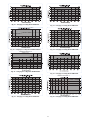
Fig. 12 – Charging in Cooling Mode 288BNV013
Fig. 16 – Charging in Cooling Mode 288BNV037
CHARGING IN COOLING MODE - 24A, 25
Liquid Service Valve Subcooling - For all AHRI listed indoor combinations
7.8
13.5
7.5
13
7.2
12.5
7.0
12
6.7
11.5
6.4
11
6.1
10.5
5.8
10
5.6
SUBCOOLING TEMPERATURE º C
SUBCOOLING TEMPERATURE º F
14
5.3
9.5
5.0
9
65
(36ºC)
70
(39ºC)
75
(42ºC)
80
(44ºC)
85
(47ºC)
90
(50ºC)
95
(53ºC)
100
(56ºC)
105
(58ºC)
Outdoor Ambient Temperature ºF (ºC)
Fig. 17 – Charging in Cooling Mode 288BNV048
Fig. 13 – Charging in Cooling Mode 288BNV0240/25
CHARGING IN COOLING MODE - 24B
Fig. 14 – Charging in Cooling Mode 288BNV024B
Fig. 18 – Charging in Cooling Mode 288BNV060
Fig. 15 – Charging in Cooling Mode 288BNV036
11
Fig. 19 – Charging in Cooling Mode 189BNV013
Fig. 23 – Charging in Cooling Mode 189BNV037
- 24A, 25
Fig. 20 – Charging in Cooling Mode 189BNV0240/25
Fig. 24 – Charging in Cooling Mode 189BNV048
CHARGING IN COOLING MODE - 24B
Fig. 21 – Charging in Cooling Mode 189BNV024B
Fig. 25 – Charging in Cooling Mode 189BNV049
CHARGING IN COOLING MODE - 60
Fig. 22 – Charging in Cooling Mode 189BNV036
Fig. 26 – Charging in Cooling Mode 189BNV060
12
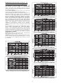
Heating Check Chart Procedure (See Fig.27 - 33)
(Communicating / Non-- communicating Systems)
Heating Check Chart - 24B
In heating mode, the required charging method is by weigh--in. On
new installations or complete recharge, refer to the unit 0 and
indoor fan coil / furnace coil per Table 1 for additional charge
needed. Refrigerant charge adjustment amount for adding or
removing 0.6 oz/ft (17.74 g/m) of 3/8 liquid line above or below
15ft (4.57 m) respectively.
Use the Defrost CHECKOUT mode to remove ice or frost from
coil, if present, prior to checking the heating pressures.
To use the Heating Check Chart, the user interface (UI) must be in
Refrigerant Charging mode selected from the Installation and
Service screen. The Charging Mode Selection screen will show
selections for Weigh--In Charge Method or Heating Check Charge
Method. Select Heating Check Charge Method. The Heating
Check Charge method will only be displayed if the conditions are
right for checking the charge in heating mode. When Heating
Check Charge Method is selected, the system will operate by
running in stage 5 with appropriate outdoor fan speed and indoor
airflow. Upon completion of a countdown period for system
stabilization, check refrigerant pressures for the appropriate
ambient temperatures shown in Fig. 27 through 33 based the OD
unit size.
To use the Heating Check Chart in non--communicating systems,
operate system at Y1+Y2–high stage. These charts indicate
whether a correct relationship exists between system operating
pressure and air temperature entering indoor and outdoor units. If
pressure and temperature do not match on chart, system refrigerant
charge may not be correct. DO NOT USE CHART TO ADJUST
REFRIGERANT CHARGE.
NOTE: High pressure is at vapor service valve. Add 12 psig if
high pressure is taken from liquid service valve.
NOTE: When charging is necessary during heating season, charge
must be weighed in accordance with unit rating plate, ±0.6 oz./ft
(±17.74 g/m). of 3/8--in. liquid--line above or below 15 ft (4.57
m), respectively.
Fig. 29 – Heating Pressure Check Chart 288BNV024B
Fig. 30 – Heating Pressure Check Chart 288BNV036
Fig. 31 – Heating Pressure Check Chart 288BNV037
Fig. 27 – Heating Pressure Check Chart 288BNV013
Heating Check Chart - 24A, 25
400
For use in Heating Charging Mode only - For all AHRI listed indoor combinations
Refrigerant Pressure (psig)
350
2413
80ºF ID (27ºC)
2068
300
250
70ºF ID (21
ºC)
60
1724
C)
ºF ID (16º
1380
200
1034
150
100
Suction Pressure
690
50
0
10
(-12ºC)
3102
2757
Vapor Service
Valve Pressure
Refrigerant Pressure (KPa)
450
Fig. 32 – Heating Pressure Check Chart 288BNV048
Heating Check Chart - 060
345
20
(-7ºC)
30
(-1ºC)
40
(4ºC)
50
(10ºC)
60
(16ºC)
65
(36ºC)
0
Outdoor Ambient Temperature ºF (ºC)
Fig. 28 – Heating Pressure Check Chart 288BNV0240, 25
Fig. 33 – Heating Pressure Check Chart 288BNV060
13
TROUBLESHOOTING
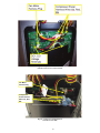
Table 3—Factory Supplied Model Plug Information
Service Tool
Fig. 34 – Service Tool Connection
A150062
When working on the outdoor unit of a split system, the technician
would usually need to repeatedly walk between the indoor wall
control and the unit outside. To save time, the communicating
controls offer a service tool feature.
By wiring the service tool into the AOC board and powering it
with an external adapter, the technician can have a wall control
capable of running the system right at the outdoor unit.
To use a service tool, connect the A and B communication bus
wires from this second communicating control to the terminals
marked A and B on the terminal strip located in the bottom left
corner of the AOC board (see Fig. 34). But instead of connecting
the wires on the service tool to the terminals marked C and D,
connect the C and D wires from the service tool to the 24V and C
on ST1 as shown in Fig. 34.
When the service tool is connected and powered up, the
communicating controls inside the home will ”go to sleep” and let
the service tool take control of the system. In this manner, the
service technician can run the diagnostic checkouts right at the
outdoor unit using the service tool.
After the checkouts are completed and it is no longer necessary to
use the service tool, remove it from the communicating controls
and the indoor communicating controls will regain control in about
two minutes.
Systems Communication Failure
If communication is lost with the User Interface (UI), the control
will flash the appropriate fault code (see Table 6). Check the wiring
to the User Interface and the indoor and outdoor units and power.
Model Plug
Each control board contains a model plug. The correct model plug
must be installed for the system to operate properly (see Table 3).
The model plug is used to identify the type and size of unit to the
control.
On new units, the model and serial numbers are inputted into the
AOC board’s memory at the factory. If a model plug is lost or
missing at initial installation, the unit will operate according to the
information input at the factory and the appropriate error code will
flash temporarily. An RCD replacement AOC board contains no
model and serial information. If the factory control board fails, the
model plug must be transferred from the original board to the
replacement board for the unit to operate.
When installing heat pump with older fan coils, a model plug
change may be required.
NOTE: The model plug takes priority over factory model
information input at the factory. If the model plug is removed after
initial power up, the unit will operate according to the last valid
model plug installed, and flash the appropriate fault code
temporarily.
288BNV
MODEL PLUG
NUMBER
13
240* 25
24B*
36
37
48
60
HK70EZ029
HK70EZ001
HK70EZ009
HK70EZ002
HK70EZ026
HK70EZ003
HK70EZ004
189BNV
MODEL PLUG
NUMBER
PIN RESISTANCE
(K--- ohms)
Pins 1--- 4
Pins 2--- 3
11K
5.1K
5.1K
5.1K
11K
5.1K
5.1K
220K
11K
91K
18K
120K
24K
33K
PIN RESISTANCE
(K--- ohms)
Pins 1--- 4
13
HK70EZ028
11K
240, 25
HK70EZ011
5.1K
24B
HK70EZ010
5.1K
36
HK70EZ012
5.1K
37
HK70EZ025
11K
48
HK70EZ013
5.1K
49
HK70EZ027
11K
60
HK70EZ014
5.1K
* 240 unit height is 38 ---7/16” and 24B unit height is 31 ---5/8”
Pins 2--- 3
180K
150K
120K
180K
91K
220K
150K
270K
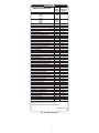
Status Codes
Table 6 shows the status codes flashed by the amber status light.
Most system problems can be diagnosed by reading the status code
as flashed by the amber status light on the control board.
The codes are flashed by a series of short and long flashes of the
status light. The short flashes indicate the first digit in the status
code, followed by long flashes indicating the second digit of the
error code.
The short flash is 0.25 seconds ON and the long flash is 1.0 second
ON. Time between flashes is 0.25 seconds. Time between short
flash and first long flash is 1.0 second. Time between code
repeating is 2.5 seconds with LED OFF.
Codes are easily read from user interface (UI)
EXAMPLE:
3 short flashes followed by 2 long flashes indicates a 32 code.
Table 6 shows this to be low pressure switch open.
Variable Speed Compressor Winding Resistance
This compressor operates with 3--phase variable frequency PWM
variable voltage. For troubleshooting certain fault codes related to
compressor resistances, follow these steps:
1. Disconnect compressor power leads from the inverter MOC
terminals, U (YEL), V (RED), and W (BLK).
2. Measure the resistance between YEL to RED, YEL to BLK,
and RED to BLK and compare to Table 4 values. Each
resistance set should be equal.
3. Measure the resistance to ground for each lead.
4. If the resistances check out, reconnect power leads to
appropriate terminal.
5. If the resistances appear to be abnormal, it will be necessary
to measure the resistance at the compressor fusite terminals.
6. During the removal of the compressor fusite cap, do not remove the RTV sealant. Remove the harness plug, measure
the resistances, and compare to Table 4.
7. Special care will need to be taken with the replacement of
the compressor fusite cap. Make sure the two holes in the
compressor fusite terminal box are still full of RTV sealant
before the cap is reinstalled. The factory RTV can be reused
as long as none of it has been removed during the cap
removal.
8. Reinstall compressor sound blanket making sure discharge
thermistor and compressor power harness are routed as they
were from the factory
14
MODEL 288BNV / 189BNV (OHMs)
WINDING
Between
terminals
240*
13, 24B*
25
36
37, 48
49 (AC),
60
.59
OHM
1.13 OHM
.59
OHM
.59
OHM
.37
OHM
.24 OHM
Between
terminal &
ground
>1 mega OHM
* 240 unit height is 38 ---7/16” and 24B unit height is 31 ---5/8”
!
CAUTION
UNIT DAMAGE HAZARD
Failure to follow this caution may result in equipment damage
and/or improper operation.
Do not use Meggar for measuring the winding resistance.
!
CAUTION
UNIT DAMAGE HAZARD
Failure to follow this caution may result in equipment damage
and/or improper operation.
To maintain water integrity of the compressor fusite terminal
box, the two holes in outer ring need to be full of RTV sealant.
Fan Motor
If verification of proper operation is required for the fan motor
used in this unit, follow these steps:
1. Disconnect fan motor connector from control board.
2. Measure resistance between any 2 of the 3 leads present.
3. Compare measurement to values below
Fan Motor Resistance
Unit Size
Resistance (Ohms)
13, 24B
21.2
240, 25, 36, 37, 48, 49 (AC), 60
11.1
Control Fault
If the outdoor unit control board has failed, the control will flash
the appropriate fault code (see Table 6). The control board should
be replaced.
Brown-- Out Protection
If the line voltage is less than 187V for at least 4 seconds, the
Compressor and OD fan goes to 0 rpm. Compressor and fan
operation are not allowed until voltage is a minimum of 190V. The
control will flash the appropriate fault code (see Table 6).
230V Line (Power Disconnect) Detection
The control board senses the presence of absence of 230V through
inverter feedback. Voltage should present at all times when system
is in service regardless if system is running or standby. If there is
no 230V at the inverter when the indoor unit is powered with a
cooling or heating demand, the appropriate fault code is displayed
on UI (communicating only – see Fig. 38). If system is configured
with conventional heat pump thermostat (non--communicating), no
fault code will be displayed on AOC board, nor will any status
LEDs be lit. Use multimeter to check for the presence of 230V in
this situation.
High Pressure Switch Protection
The outdoor unit is equipped with high pressure switch. If the
control senses the opening of a high pressure switch (open 520+/--5
psig, close 470+/--10 psig @77_F), it will respond as follows:
1. Display the appropriate fault code (see Fig. 38).
2. After a 15 minute delay, if there is a call for cooling or heating and HPS is reset, the PEV opens for 150 seconds to
equalize system pressures. The compressor and fan will then
ramp to the next lower stage of operation until demand is
satisfied. In the next call for heating/cooling system will resume normal operation.
3. If the opened switch closes at any time after the 15 minute
delay, then the PEV opens for 150 seconds to equalize system pressures. The compressor and fan will then ramp to the
next lower stage of operation until demand is satisfied. In
the next call for heating/cooling system will resume normal
operation.
4. If HPS trips 3 consecutive cycles, the unit operation is
locked out for 4 hours.
5. In the event of a high--pressure switch trip or high--pressure
lockout, check the refrigerant charge, outdoor fan operation,
and outdoor coil (in cooling) for airflow restrictions, or indoor airflow in heating.
6. In the event of a low--pressure trip or low--pressure lockout,
check the refrigerant charge and indoor airflow (cooling)
and outdoor fan operation and outdoor coil in heating.
Low Pressure Protection
The outdoor unit is equipped with suction pressure transducer. If
suction pressure drops below 15 psi at any time, or below 33 psi
for 5 minutes, the compressor and fan will stop running and an
error code will be displayed on user interface.
1. If there is still a demand for unit operation after the 15
minute delay and pressure has increased to >43psi (cooling)
and >35psi (heating) , system will resume operation.
2. If there are three (3) consecutive trips because of suction
pressure dropping below 15 psi, the low pressure switch
will lock out operation for 4 hours. Trip counter will be
reset after 15 minutes of successful operation.
3. When a change in demanded stage occurs, suction pressure
will be checked at each stage in between current and
demanded stage. This is to prevent ramping of compressor
speed too quickly and creating a low pressure situation. As
long as suction pressure is >=45psi, the compressor is able
to ramp to next stage. If suction pressure is lower than
required, additional wait time at current stage will occur.
Suction Pressure Transducer (SPT)
If the accuracy of the transducer is questioned, the technician can
check it while it is attached to the AOC board. Connect a gage
manifold to the suction valve gage port fitting.
At the AOC board, with the wire harness receptacle exposing a
portion of the three pins on the AOC board, a DC voltmeter can
read the DC voltage between ground and supply (input) terminal.
Ensure that the input voltage is 5 VDC. Next, read the DC voltage
across the ground and output terminal. Record the output voltage.
The suction pressure that the pressure transducer is reading can be
calculated by taking the output voltage and subtracting 0.5 from it
then taking that difference and multiplying it by 50. Pressure
(psig) = 50.0 x (DCV out -- 0.5). For example, if the measured
voltage is 3.0 VDC: 50 X (3.0 -- 0.5) -- 50 X 2.5 = 125 psig. See
Fig. 35.
6
5
4
Output Voltage (V)
Table 4—Variable Speed Compressor Resistance
(winding resistance at 70_F 20_F)
3
2
1
0
0
25
50
75
100
125
150
175
200
225
Pressure - Sealed Gauge (psi)
Fig. 35 – Suction Pressure Transducer (SPT)
Output Funtion Graph
15
A12035
Temperature Thermistors
Thermistor Sensor Comparison
Thermistors are electronic devices which sense temperature. As the
temperature increases, the resistance decreases.
10Kohm
thermistors are used to sense outdoor air temperature (OAT), coil
temperature (OCT) and the suction line temperature (OST) located
between the reversing valve and the accumulator. A 50Kohm
thermistor is used to sense discharge temperature (ODT).
Refer to Table 5 and Fig. 36 and 37 for resistance values versus
temperature.
The control continuously monitors and compares the outdoor air
temperature sensor and outdoor coil temperature sensor to ensure
proper operating conditions. The comparison is:
S In cooling if the outdoor air sensor indicates 10_F ( 5.6_C)
warmer than the coil sensor (or) the outdoor air sensor indicates
25_F ( 15_C) cooler than the coil sensor, the sensors are out
of range.
S In heating if the outdoor air sensor indicates 35_F ( 19.4_C)
warmer than the coil sensor (or) the outdoor air sensor indicates
10_F ( 5.6_C) cooler than the coil sensor, the sensors are out
of range.
If the sensors are out of range, the control will flash the appropriate
fault code as shown in Table 6.
The thermistor comparisons are not performed during low ambient
cooling or defrost operation.
Table 5—10K/50Kohm Resistance Values vs Temperature
10Kohm
_C (_F)
TEMPERATURE
25.0 (77.0)
0.0 (32.0)
-28.0 (-18.4)
50Kohm
125.0 (257.0)
75.0 (167.0)
25.0 (77.0)
RESISTANCE (ohms)
10.0 + / --- 2.3%
32.6 + / --- 3.2%
85.5 + / --- 3.4%
1.7 + / --- 1.6%
7.40 + / --- 2.0%
50.0 + / --- 2.3%
Failed Thermistor Default Operation
Factory defaults have been provided in the event of failure of
outdoor air thermistor (OAT) and/or outdoor coil thermistor
(OCT).
If the OAT sensor should fail, defrost will be initiated based on coil
temperature and time.
If the OCT sensor should fail, defrost will occur at each time
interval during heating operation, but will terminate after 2
minutes.
If there is a thermistor out--of--range error, defrost will occur at
each time interval during heating operation, but will terminate after
2 minutes.
Count the number of short and long flashes to determine the
appropriate flash code. Fig. 38 and Table 6 gives possible causes
and actions related to each error.
THERMISTOR CURVE
90
RESISTANCE (KOHMS)
80
70
60
50
40
30
20
10
0
0
20
40
60
80
TEMPERATURE (DEG. F)
100
120
A91431
Fig. 36 – 10K Thermistor Resistance Versus Temperature
RESISTANCE (KOHMS)
50K THERMISTOR
450
400
350
300
250
200
150
100
50
0
0
20
40
60
80
100
120
TEMPERATURE (°°F)
A14022
Fig. 37 – 50K Thermistor Resistance Versus Temperature
If the outdoor air or coil thermistor should fail, the control will
flash the appropriate fault code (see Table 6).
IMPORTANT: The outdoor air thermistor, coil thermistor and
suction thermistor should be factory mounted in the final locations.
Check to ensure thermistors are mounted properly (See Fig. 2,
3, 4, 5 and 6).
16
SERVICE
* FLASH
CODE
RESET TIME
(Minimum)
Minutes
(Amber LED)
AMBER LED DESCRIPTION
Standby
Variable
Capacity
Mode
Variable
Speed
Range
Cutback
Communications Loss
Invalid Model
High Pressure Switch Open
Low Pressure Trip
Control Fault
Brownout Event
Lost Inverter Communications
230VAC Dropout-Reset Event
Discharge Temp Sensor Fault
Outdoor Air Temp Sensor Fault
Suction Temp Sensor Fault
Coil Temp Sensor Fault
OAT-OCT Thermistor Out of Range
Suction Pressure Sensor Fault
Suction Thermistor Range Fault
Discharge Temperature Out of Range Event
Fan Inverter Fault
Fan Inverter Temp High
Fan Inverter Over Current - SPD Limiting
D C Voltage Low - SPD Limiting
Outdoor Fan Dropped Out
Stator Heater Fault
10 Minute Stage 2 Warmup Delay
Inverter / Compressor Internal Fault
Compressor Dropped Out
Suction Over Temperature Event
Discharge Temp Out of Range Lockout
Maximum Power Mode-Temp
Fan Inverter Lockout
Maximum Power Mode-Comp Current
Compressor/Inverter Fault
Suction Over Temp Lockout
Low Pressure Lockout for 4 hours
High Pressure Lockout for 4 hours
Fan Inverter Temp Lockout
Fan Inverter Current Lockout
Inverter Temp Lockout
Compressor Inverter Overcurrent Lockout
Inverter VDC-Out Over Voltage Event
Inverter VDC-Out Under Voltage Event
230VAC Under Voltage Event
230VAC Over Voltage Event
High Current Lockout
VDC Under Voltage Lockout
VDC Over Voltage Lockout
High Torque Event
High Torque Lockout
--
ON, no flash
--
1, pause
--
1 (2 sec ON),
longer pause
(1 second OFF)
--
16
25
31
32
45
46
48
49
52
53
54
55
56
57
58
59
61
62
63
65
66
67
68
69
71
72
74
75
76
77
79
82
83
84
85
86
88
89
91
92
93
94
95
96
97
98
99
OFF
N/A
N/A
15
15
N/A
6
6
6
N/A
N/A
N/A
N/A
N/A
15
N/A
15
6
6
6
6
6
6
10
15
6
15
2 Hours
N/A
2 Hours
N/A
15
4 Hours
4 Hours
4 Hours
15
15
2 Hours
15
15
15
15
15
2 Hours
2 Hours
2 Hours
10
2 Hours
N/A
* Short Flashes indicate the first digit in
the status code followed by long flashes
indicating the second digit of the status code.
341475-101 REV. A
Fig. 38 – Fault Code Label
17
Table 6—Fault Code Actions
Flash Code
Type
ON, no flash
1, pause
1 (2 sec ON),
longer pause (1
second OFF)
16
25
AMBER LED DESCRIPTION
Reset
Time
Mode
Possible Causes
Standby
Variable Capacity
Variable Capacity (Range
Cutback)
Fault
System
Malfunction
COMMUNICATIONS LOSS
NA
Both
Loose wire or shorted
leads
Verify communications wiring (ABCD); check
for loose connection, stripped wires, short to
ground or short between wires
Wrong Model Plug Installed
Verify correct model plug installed
Damaged Model Plug
Check model plug for corrosion or breakage;
replace if necessary
Data Bus locked up
by power loss,
brownout or glitch
UI software update
Damaged AOC control
Wrong Model Plug Installed
Damaged Model Plug
INVALID MODEL
NA
Both
15 Min.
(then reduced
stage operation)
Both
High Pressure Event
Missing model plug
on service board
Damaged AOC control
31
Event
HIGH PRESSURE SWITCH
OPEN
32
Event
LOW PRESSURE TRIP
15 Min.
Both
Low Pressure Event
45
System
Malfunction
CONTROL FAULT
NA
Both
Damaged AOC control
46
Event
BROWNOUT EVENT
6 Min.
Both
48
System
Malfunction
LOST INVERTER COMMUNICATIONS
6 Min.
Both
49
Fault
230VAC DROPOUT ---RESET
EVENT
6 Min.
Both
52
53
54
Actions
Fault
Fault
Fault
DISCHARGE TEMP SENSOR FAULT
OUTDOOR AIR TEMP SENSOR FAULT
SUCTION TEMP SENSOR
FAULT
NA
NA
NA
Both
Both
Both
18
low line voltages
Loose or disconnected harness
Possible damage to
VSD
Voltage glitches and
low line voltages
Damaged Inverter
Drive
Sensor Harness not
connected to AOC
control
Broken or loose harness wire
Broken or Damaged
Sensor
Hardware damage to
AOC control
Sensor Harness not
connected to AOC
control
Broken or loose harness wire
Broken or Damaged
Sensor
Hardware damage to
AOC control
Sensor Harness not
connected to AOC
control
Broken or loose harness wire
Suction Thermistor
not properly attached
or in wrong location
Broken or Damaged
Sensor
Hardware damage to
AOC control
Cycle Power to system
Ignore fault in history
Replace AOC control
Verify correct model plug installed
Check model plug for corrosion or breakage;
replace if necessary
Re ---install original model plug
Replace AOC control
System will self ---mitigate by reducing the
stage, persistent conditions will lead to lockout (refer to Error Code 84). 2 hours of accumulated operation without further fault will
reset fault counter
System will self ---mitigate, persistent conditions will lead to lockout (refer to Error Code
83) 2 hours of accumulated operation without
further fault will reset fault counter
Power cycle, Replace AOC control
if persistent contact power provider
Verify good harness connection
change out the Inverter drive
if persistent contact power provider
Change out ODU control before Inverter
Drive; if this does not help then change out
the Inverter drive
Ensure plug is connected to AOC control
Check harness for continuity; resistance
should be in 10 kOhm
Check harness for continuity; resistance
should be in 10 kOhm
Replace AOC control
Ensure plug is connected to AOC control
Check harness for continuity; resistance
should be in 10 kOhm
Check harness for continuity; resistance
should be in 10 kOhm
Replace AOC control
Ensure plug is connected to AOC control
Check harness for continuity; resistance
should be in 10 kOhm
Ensure Sensor is properly attached to the accumulator entry ---tube
Check harness for continuity; resistance
should be in 10 kOhm
Replace AOC control
Table 6—Fault Code Actions (continued)
Flash Code
55
56
57
Type
Fault
Event
Fault
AMBER LED DESCRIPTION
COIL TEMP SENSOR FAULT
OAT ---OCT THERMISTOR
OUT OF RANGE
SUCTION PRESSURE SENSOR FAULT
Reset
Time
NA
NA
15 Min.
Mode
Both
Both
Both
Possible Causes
Sensor Harness not
connected to AOC
control
Broken or loose harness wire
Coil Thermistor not
properly attached or
in wrong location
Broken or Damaged
Sensor
Hardware damage to
AOC control
Coil Thermistor not
properly attached or
in wrong location
Outdoor Ambient
Temperature sensor
improperly installed
(sensor body may be
in contact with sheet
metal)
Sensor Harness not
connected to AOC
control
Broken or loose harness wire
Electrical short destroyed Transducer
electronics
Heat damage during
brazing
58
Fault
SUCTION THERMISTOR
RANGE FAULT
NA
Both
Both
Both
59
Event
DISCHARGE TEMP OUT OF
RANGE EVENT
Both
15 Min.
Cool
Heat
Heat
Suction Thermistor
not properly attached
or in wrong location
Broken or loose harness wire
Outdoor Air Thermistor Issue
Indoor Unit Airflow
too low or off
Outdoor Unit Airflow
too low or off
Reversing Valve Bypass
High Load conditions
Low Charge or Loss
of Charge at low ambient heating conditions
Expansion Valve Orifice too small
OFM failed to start
61
Fault
FAN INVERTER FAULT
6 Min.
Both
62
Fault
FAN INVERTER TEMPERATURE HIGH
6 Min.
Both
63
Fault
FAN INVERTER OVER CURRENT
6 Min.
Both
Sudden supply voltage change
Sudden load change
on fan/motor
65
Fault
DC VOLTS LOW FAULT
6 Min.
Both
Possible nuisance trip
66
Fault
OUTDOOR FAN DROPPED
OUT
6 Min.
Both
67
Fault
STATOR HEATER FAULT
6 Min.
Both
68
Event
10 MINUTE STAGE 2
WARM ---UP DELAY
10 Min.
Both
Possible nuisance trip
Unusual loading of
the fan
Improper airflow
across VSD heat sink
MOC is reporting that
OFM isn’t running
There is a demand for
stator heat but MOC
doesn’t detect it
High voltage power
cycle
Phase imbalance
69
System
Malfunction
INVERTER/COMPRESSOR
INTERNAL FAULT
15 Min.
Both
19
Inverter damage
Flooded start
Incorrect refrigerant
charge
Actions
Ensure plug is connected to AOC control
Check harness for continuity; resistance
should be in 10 kOhm
Ensure Sensor is properly clipped to the distributor entry ---tube
Check harness for continuity; resistance
should be in 10 kOhm
Replace AOC control
Ensure Sensor is properly clipped to the distributor entry ---tube
Properly install OAT sensor
Ensure plug is connected to AOC control
Check harness
Compare transducer reading to gauge reading
at service valve (see transducer measurement
chart); Check system for electrical shorts and
correct; replace transducer
Compare transducer reading to gauge reading
at service valve (see transducer measurement
chart); replace transducer
Ensure plug is properly attached to suction
tube
Check harness for continuity; resistance
should be in 10 kOhm
See Error 53 and\or Error 56
Troubleshoot indoor fan motor and make sure
it is working
Troubleshoot outdoor fan motor and make
sure it is working
Reversing Valve Stuck halfway
Over charge: Check system charge
Undercharged or No charge: check charge
Heating: Trouble shoot EXV (coil, harnesses);
Trouble shoot the TXV
Troubleshoot outdoor fan motor & blade and
make sure they are working
System will try to self ---mitigate
Troubleshoot outdoor fan motor & blade and
make sure they are working
Check for fan outlet blockage due to snow/ice
etc.
Inspect outdoor coil for obstructions
Investigate incoming voltage
Troubleshoot outdoor fan motor & blade and
make sure they are working
System will try to self ---mitigate with speed reducing.
Troubleshoot outdoor fan motor and make
sure it is working
Check compressor winding resistance or mis--wire of compressor leads at terminals U,V,W
No action
Check compressor winding resistance or mis--wire of compressor leads at terminals U,V,W
Replace inverter
Troubleshoot EXV & TXV
Check refrigerant amount
Table 6—Fault Code Actions (continued)
Flash
Code
71
Type
Fault
72
Fault
74
System Malfunction
75
Event
76
System
Malfunction
77
Event
AMBER LED DESCRIPTION
Compressor Dropped Out
Suction Over Temp Event
DISCHARGE TEMP OUT OF
RANGE LOCKOUT (lockout occurs after 59 fault repeats and
stage can no longer be lowered)
MAXIMUM POWER MODE --TEMP (Temporary RPM reduction or stage lowering will result.
Lockout occurs after 75 fault repeats and stage can no longer
be lowered)
FAN INVERTER LOCKOUT (repeated code 61 3X)
Reset
Time
Mode
Both
15 Min.
Both
Cool
Cool
Heat
Both
2 Hours
Both
See fault 59
Outdoor Airflow too low or off
NA
Both
2 Hours
Both
MAXIMUM POWER MODE --CURRENT (Temporary RPM reduction or stage lowering will result. Lockout occurs after 77
fault repeats and stage can no
longer be lowered)
NA
Both
Fault
COMPRESSSS/INVERTER
FAULT
15 Min.
Both
82
System Malfunction
SUCTION OVER TEMP LOCKOUT (lockout occurs after 72
fault repeats 3X)
4 Hours
Both
Cool
Cool
Cool
System Malfunction
LOW PRESSURE LOCKOUT 4
HOURS (lockout occurs after 32
fault repeats 3X)
Actions
Check compressor winding resistance or mis---wire
of compressor leads at terminals U,V,W
Check refrigerant amount
Insulate the vapor line
Troubleshoot TXV
Troubleshoot EXV
troubleshoot reversing valve
6 Min.
79
83
Possible Causes
MOC is reporting that compressor isn’t running
Incorrect refrigerant charge
Uninsulated vapor line
Indoor TXV operation
Outdoor EXV operation
Reversing valve bypass
4 Hours
Blocked Inverter Heat Exchanger (fins)
Application violates guideline
If the fault repeats, possible
inverter damage
Compressor is operating outside the allowed operational
envelope
Incorrect refrigerant charge
Outdoor Airflow too low or off
Incoming power supply voltage
Loose or incorrect wire connections
Compressor stops or fails to
start
Inverter Damage
Compressor Damage
See fault 72
Cooling in Low Ambient region (55 ° F and below) with
”Low Ambient Cooling Control” disabled
Outside Normal Operating
Range (e.g. improper load
calculation, system match issue, outside cooling range
etc)
Service Valve left closed (Liquid or Vapor)
Cool
Undercharged System
Cool
Indoor Airflow too low or off
Cool
Restriction in Filter Drier plus
Long Line Application and filter drier on Indoor Unit
Cool
Restriction due to debris
Cool
Both
Both
Heat
Heat
Heat
Restriction in Circuits or Tubing
Restriction in Filter Drier plus
filter drier on Outdoor Unit
Expansion Orifice Restriction
Outside Normal Operating
Range (e.g. improper load
calculation, system match issue, outside heating range
etc)
Service Valve left closed (Liquid Service Valve)
Heat
Outdoor Airflow too low or off
Heat
Undercharged System
Heat
Reversing Valve Bypass
Heat
Restriction due to debris
20
Same actions for 59
Check ODU coil for clogging (ice or debris) and
clean if necessary; Troubleshoot ODU fan motor and
make sure it is working
Check Inverter fins for debris and clean if necessary
Consult Application Guideline for compliance
Replace inverter
Inverter will reduce speed to a lower stage
Check refrigerant amount
Check ODU coil for clogging (ice or debris) and
clean if necessary; Troubleshoot ODU fan motor and
make sure it is working
Check voltage versus unit rating plate for allowable
range
Check incoming power leads and leads to the compressor plug
System will try to self---mitigate with repeated start
attempts. If it repeats, check wiring.
Replace Inverter
Replace Compressor
Same actions for 72
Enable ”Low Ambient Cooling” via user interface
Consult Application Guidelines
Ensure Service Valves are open
Check system subcooling to determine charge status, if low add charge using Charging Mode (follow
proper charging procedures)
Check Indoor for clogging (ice or debris) and clean
or de---ice if necessary; Troubleshoot Indoor fan motor and make sure it is working; follow Indoor Airflow
troubleshooting instruction
Clean System (refer to application guideline) and
replace filter drier
Clean System (refer to application guideline) and
replace filter drier
Check kinks and straighten or replace circuits
Clean System (refer to application guideline) and
replace filter drier
If short lineset (less than 15 ft) Troubleshoot TXV (see
guide below); replace if necessary
Troubleshoot EXV (see guide below)
Consult Application Guidelines
Ensure Liquid Service Valve is open
Check Outdoor for clogging (ice or debris) and clean
or de---ice if necessary; Troubleshoot Outdoor fan
motor and make sure it is working; follow Outdoor
Airflow troubleshooting instruction
Check charge in cooling (if in Cooling Charge Mode
Ambient Range), if low add charge using Charging
Mode (follow proper charging procedures); if outside
cooling charge mode range, pull out charge, weigh
in using heating charge mode
Reversing Valve Stuck halfway; troubleshoot reversing valve
Clean System (refer to application guideline) and
replace filter drier
Table 6—Fault Code Actions (continued)
Flash Code
Type
AMBER LED DESCRIPTION
Reset
Time
Mode
Both
Both
Both
Both
Both
Both
Both
Cool
84
System
Malfunction
HIGH PRESSURE LOCKOUT
4 HOURS (lockout occurs after 31 fault repeats 3X and
stage can no longer be lowered)
4 Hours
Possible Causes
Outside Normal Operating Range (e.g. improper load calculation, system match issue, outside cooling
range, outside heating range etc)
loose High Pressure
Switch harness leads
Pressure Switch disconnected from ODU
Control Board
Faulty Pressure
Switch
Restriction due to debris leading to Overcharge when charging in Cooling mode
Restriction in EXV
plus Long Line Application leading to
Overcharge when
charging in Cooling
mode
None condensable
leading to high load
Service Valve left
closed (Liquid or Vapor)
Cool
Overcharged System
Cool
Outdoor Airflow too
low or off
Cool
Cool
Cool
Heat
Heat
Heat
Heat
Heat
Restriction in Filter
Drier plus Long Line
Application and filter
drier on Outdoor Unit
Restriction in EXV
plus Overcharge
Restriction in Circuits
or Tubing
Electric Heater plus
Heat pump application: Electric Heater
stuck on
Furnace plus Heat
pump application:
Furnace stuck on
Restriction in Filter
Drier plus Long Line
Application and filter
drier on Indoor Unit
Expansion Orifice Restriction
Heat
Service Valve left
closed (Vapor Service
Valve)
Heat
Indoor Airflow too low
or off
Heat
Overcharged System
Heat
Heat
21
Reversing Valve
Stuck in Cooling
Restriction due to debris
Actions
Consult Application Guidelines
Check HPS harness
Check HPS connection on ODU control
Check Discharge pressure with gauge, if less
than 610 +/ --- 20 psig and switch is open
(measure resistance) then replace pressure
switch
Clean System (refer to application guideline)
and replace filter drier
If long line, troubleshoot EXV
Clean System (refer to application guideline)
and replace filter drier
Ensure Service Valves are open
Check system charge using Cooling Charging
Mode (follow proper charging procedures)
Check Outdoor Coil for clogging (ice or debris) and clean or de ---ice if necessary; Troubleshoot Outdoor fan motor and make sure it
is working; follow Outdoor Airflow troubleshooting instruction
Clean System (refer to application guideline)
and replace filter drier
troubleshoot EXV
Check kinks and straighten or replace circuits
If User Interface is not requesting Electric Heat
check for heater relays, if on troubleshoot
Electric Heater
If not in Defrost and Furnace is running same
time as heat pump, troubleshoot Furnace
Clean System (refer to application guideline)
and replace filter drier
Troubleshoot TXV
Troubleshoot EXV
Ensure Vapor Service Valve is open
Check Indoor for clogging (ice or debris) and
clean or de ---ice if necessary; Troubleshoot
Indoor fan motor and make sure it is working;
follow Indoor Airflow troubleshooting instruction
Check charge in cooling (if in Cooling Charge
Mode Ambient Range), if low add charge using Charging Mode (follow proper charging
procedures); if out side cooling charge mode
range, pull out charge, weigh in using heating
charge mode
troubleshoot reversing valve
Clean System (refer to application guideline)
and replace filter drier
Table 6—Fault Code Actions (continued)
Flash Code
85
86
88
Type
System Malfunction
System Malfunction
System Malfunction
AMBER LED DESCRIPTION
FAN INVERTER TEMP LOCKOUT (lockout occurs after 62
fault repeats 3X)
FAN INVERTER CURRENT
LOCKOUT (lockout occurs after 63 fault repeats 3X)
INVERTER TEMP LOCKOUT
(79 fault repeats 3X)
Reset
Time
15 Min.
15 Min.
2 Hours
Mode
Both
See fault 62
Both
Inverter damage
Both
See fault 63
Both
Inverter damage
Both
Blocked Inverter Heat
Exchanger (fins)
Both
Evaporator Airflow too
low or off
Both
Condenser Airflow too
low or off
Both
Both
Both
89
System Malfunction
COMP INVERTER OVER
CURRENT LOCKOUT
15 Min.
Both
91
Event
INVERTER VDC---OUT OVER
VOLTAGE EVENT
15 Min.
Both
92
Event
INVERTER VDC---OUT UNDER VOLTAGE EVENT
15 Min.
Both
93
Event
230VAC UNDER VOLTAGE
EVENT
15 Min.
Both
94
Event
230VAC OVER VOLTAGE
EVENT
15 Min.
Both
95
96
97
98
99
System Malfunction
System Malfunction
System Malfunction
Event
System Malfunction
HIGH CURRENT LOCKOUT
(lockout occurs after repeated
77 faults and lowest stage is
reached)
VDC UNDER VOLTAGE
LOCKOUT (lockout occurs after repeated 93 faults)
VDC OVER VOLTAGE LOCKOUT (lockout occurs after repeated 94 faults)
HIGH TORQUE EVENT
HIGH TORQUE LOCKOUT
2 Hours
2 Hours
2 Hours
10 Min.
2 hours
Possible Causes
Both
Both
Both
Both
High Load conditions
at cold ambient heating or high ambient
cooling
Compressor damage
Inverter damage
Phase imbalance
Inverter damage
Occurs when bus voltage exceeds 410 VDC
Compressor is suddenly unloaded
Inverter damage
Occurs when bus voltage falls below 220
VDC
Occurs when incoming voltage is less than
197 VAC
Occurs when incoming voltage is more
than 253 VAC
Compressor is operating outside the allowed operational envelope
Incorrect refrigerant
charge
Outdoor Airflow too
low or off
Incoming power supply voltage
Loose or incorrect wire
connections
Compressor internal
damage
Low supply line voltage (< 197 VAC)
Storm weather causing intermittent voltage
dropouts
Loose wire in control
box area
Inverter internal damage
High supply line voltage (> 253 VAC)
Storm weather causing intermittent voltage
spikes
Inverter internal damage
Compressor is operating outside the allowed operational envelope
Both
Mis---wire
Both
Incorrect refrigerant
charge
Both
Outdoor Airflow too
low or off
Cool
Heat
TXV issue
EXV issue
22
Actions
Same actions for 62
Replace inverter
Same actions for 63
Replace inverter
Check Inverter fins for debris and clean if necessary
Check Evaporator (IDU in cooling, ODU in heating) for clogging (ice or debris) and clean if necessary; Troubleshoot Evaporator fan motor and
make sure it is working
Check Condenser (IDU in heating, ODU in cooling) for clogging (ice or debris) and clean if necessary; Troubleshoot Condenser fan motor and
make sure it is working
Over charge: Check system charge
Replace compressor
Replace inverter
Check compressor winding resistance or mis--wire of compressor leads at terminals U,V,W
Replace inverter
Check operation of compressor
Check that the service valves are fully open
Replace inverter
Check for interruption in main power supply
System will try to ride through voltage spikes
and self---recover in trip condition; persistent
over current trips will lead to SM 96
System will try to ride through voltage spikes
and self---recover in trip condition; persistent
over current trips will lead to SM 97
Inverter will reduce speed to a lower stage
Check refrigerant amount
Check ODU coil for clogging (ice or debris) and
clean if necessary; Troubleshoot ODU fan motor
and make sure it is working
Check voltage versus unit rating plate for allowable range
Check incoming power leads and leads to the
compressor plug
Replace compressor
Check supply voltage to ODU; if low contact
utility provider
When adverse weather subsides unit should
self---recover; cycle ODU power if necessary
Loose wire: check for loose wire in ODU
Replace Inverter
Check supply voltage to ODU; if high contact
utility provider
When adverse weather subsides unit should
self---recover; cycle ODU power if necessary
Replace Inverter
Inverter will reduce speed to a lower stage
Check mis---wire of compressor leads at terminals U,V,W
Check refrigerant amount
Check ODU coil for clogging (ice or debris) and
clean if necessary; Troubleshoot ODU fan motor
and make sure it is working
Troubleshoot TXV
Troubleshoot EXV
Variable Speed Drive LED Location and Description (Sizes 240, 25, 36, 37, 48, 49 and 60)
MOC LED Description (Sizes 240, 25, 36, 37, 48, 49 AND 60)
Reference
Color
LD1
Red
LED1
Red
LED3
Amber
LD5
Green
Reference
Color
STATUS
Amber
COMM
Green
Reference
Color
STATUS
Amber
COMM
Green
Status
Steady On
Off
Steady On
Off
Steady On
Off
Blinking
Steady On
Off
Description
MOC powered where DC bus is 40volts or greater
No power, capacitor voltage drained
DCF and board DC high voltage and discharge circuit powered on
No power
MOC board switching power supply to power AOC board on
No Power
Indicates communication from MOC to AOC
Indicates 5 volt connection status OK between AOC and MOC
No Power
AOC LED Descriptions (Sizes 240, 25, 36, 37, 48, 49 AND 60)
Status
Steady On
Blinking
Steady On
Description
AOC status --- standby mode
AOC function/fault status
Communication from AOC to indoor wall control
LED Not Functioning Properly --- Requires AOC Replacement
Suspect AOC board
If Amber STATUS light is not on (neither steady nor blinking), with power to outdoor unit
In Communicating mode, if Green COMM LED is not on
when AB indoor wires are connected to AOC AB connector
and indoor has communications
Failure Description
AOC STATUS is not functioning properly and AOC board
should be replaced.
AOC is not capable of communicating with indoor; AOC
board should be replaced.
Fault Codes requiring AOC Replacement
Fault Code Description
Fault Flash Code
Communications Loss
179
Control Fault
(Internal Board Failure)
45
Failure Description
Loss of communication with outdoor unit AOC board;
AOC or Inverter may need to be replaced
AOC board has failed; AOC board should be replaced.
NOTE: If any of the AOC control board header pins are damaged or are not making good contact, AOC board should be replaced.
23
Variable Speed Drive LED Location and Description (Sizes 13 and 24B)
LED 200
LED 207
STATUS
COMM
MOC LED Description (Sizes 13 and 24B)
Reference
LED200
Color
Status
Steady
On
Off
Steady
On
Red
LED207
Amber
Condition
Description
Normal
Indicates MOC powered where DC bus at 40volts or higher
Abnormal
No power, capacitor voltage drained
Normal
Blinking
Abnormal
Off
Normal
Compressor is running
If compressor stops, it indicates some fault happening;
If compressor is running, it indicates speed is limited or reduced.
Compressor stops and no fault
AOC LED Descriptions (Sizes 13 and 24B)
Reference
Color
STATUS
Amber
COMM
Green
Status
Steady
On
Blinking
Steady
On
Condition
Description
Normal
AOC status---standby mode
Abnormal
AOC function/fault status
Normal
Communication from AOC to indoor wall control
LED Not Functioning Properly --- Requires AOC Replacement
Reference
Color
STATUS
Amber
COMM
Green
Suspect AOC board
If Amber STATUS light is not on (neither steady nor blinking), with power to outdoor unit
In Communicating mode, if Green COMM LED is not on
when AB indoor wires are connected to AOC AB connector
and indoor has communications
Failure Description
AOC STATUS is not functioning properly and AOC board
should be replaced.
AOC is not capable of communicating with indoor; AOC
board should be replaced.
Fault Codes requiring AOC Replacement
Fault Code Description
Fault Flash Code
Communications Loss
179
Control Fault
(Internal Board Failure)
45
Failure Description
Loss of communication with outdoor unit AOC board;
AOC or Inverter may need to be replaced
AOC board has failed; AOC board should be replaced.
NOTE: If any of the AOC control board header pins are damaged or are not making good contact, AOC board should be replaced.
24
COMPRESSOR POWER HARNESS ASSEMBLY REPLACEMENT
(Reference RCD Instruction # 99TA516170)
The following is a recommended procedure for compressor power
harness replacement. Always refer to the unit product installation,
start--up & service instructions for detailed procedures.
!
WARNING
ELECTRICAL SHOCK HAZARD
Failure to follow this warning could result in personal injury
or death.
Turn off and lock out all power to unit before proceeding.
Discharge all capacitors before proceeding
All wiring and electrical connections shall comply with all
local and national electrical codes.
!
WARNING
7. Remove top two screws holding control box and remove
compressor harness (highlighted in yellow below).
ELECTRICAL SHOCK HAZARD
Failure to follow this warning could result in personal injury
or death.
failure to follow this warning could result in personal injury.
Do not operate compressor or provide any electrical power to
the compressor unless the terminal box cover is in place and
secured.
Measurements of amps and volts during running conditions
must be taken at other points in the power supply.
Do not provide any power to the compressor unless suction
and discharge service valves are open.
Replacement Procedure
1. Follow all safety warnings and notices.
2. Precautions must be taken when servicing components
within the control box of this unit. The technician
performing the service must determine that it is safe to work
on or near the inverter. The electrical disconnect that
provides power to the unit must be turned off, locked and
tagged out. This will insure that no damage will occur to the
inverter, controls or other equipment and will prevent injury
if contact is made with the electrical equipment. Wait a
minimum of two minutes before servicing the unit to allow
inverter capacitors to discharge. Follow safety instructions
located on unit control box cover.
3. Remove the control box cover.
4. Disconnect compressor power harness from inverter.
5. Remove service panel to gain access to unit wiring and
compressor compartment.
6. Cut the wire tires securing the compressor power harness to
the control box. Remove compressor power harness (from
control box). Replace wire tie with supplied wire tie; do not
fasten at this time. The second wire tie for the choke on the
compressor is supplied with new harness on the replacement
compressor (highlighted with the yellow circles below).
8. Cut double loop wire tie on suction tube holding
compressor harness, replace with new one provided; do not
fasten at this time. Note how the compressor harness is
routed to suction tube. (Highlighted in yellow below)
25
9. With using a slot screwdriver, lift up the on the side tab to
pry the cover off from the RTV. Be sure not to break the tab.
12. Remove cover, unplug old harness, plug in new harness,
verify bushing is reinstalled and plug leads leave the
terminal box through the bushing; reinstall cover pushing
one side down then the other.
NOTE: DO NOT SCRAP SEALANT
10. It may be necessary to leverage the screwdriver against
cover next to tab so as not to break the tab while loosening.
13. Reinstall compressor sound blanket making sure discharge
thermistor and compressor power harness are routed as they
were from the factory.
14. Route compressor power harness to new double loop wire
tie and then to the wire retainers in tube sheet (route as they
were originally to make sure they will not contact fan blade)
and then route into control box and reinstall two control
box screws. (See image below)
11. Once Cover is loosened on one side, use screwdriver along
freed edge to remove.
15. Reinstall service panel.
16. Route compressor harness choke to left hand side of the top
of control box and push in wire tie. Pull wires tight as they
enter control box and tighten second wire tie.
17. Reconnect compressor power harness to the inverter.
NOTE: Reference enclosed wiring diagrams and unit
wiring diagrams in Owner’s Manual to aid in reattaching
electrical connections.
18. Reinstall control box cover.
26
INVERTER ASSEMBLY w SHIELD GASKET REMOVAL AND INSTALLATION
(Reference RCD Instruction # 99TA512018) Also see figures 39 through 42
!
WARNING
ELECTRICAL SHOCK HAZARD
Failure to follow this warning could result in personal injury
or death.
Turn off the electrical supplies to the unit before performing
any maintenance or service. Follow the operating instructions
on the label attached to the unit
!
CAUTION
ELECTRICAL OPERATION HAZARD
Failure to follow this caution may result in unit damage or
improper operation.
Label all wires prior to disconnection when servicing controls.
Wiring errors can cause improper and dangerous operation.
IMPORTANT: DO NOT USE POWER TOOLS TO
TIGHTEN THE INVERTER INPUT SCREW TERMINALS
Removing Inverter:
1. Remove power to the unit. Wait a minimum of two minutes
before servicing the unit to allow inverter capacitors to
discharge. Follow safety instructions located on unit control
box cover.
2. Precautions must be taken when servicing components
within the control box of this unit. The technician
performing the service must determine that it is safe to work
on or near the inverter. The electrical disconnect that
provides power to the unit must be turned off, locked and
tagged out. This will insure that no damage will occur to the
inverter, controls or other equipment and will prevent injury
if contact is made with the electrical equipment.
3. Remove the control box cover.
4. The inverter capacitors are covered with a protective shield.
The shield should not be removed from the inverter.
5. Before servicing the inverter, verify the inverter voltage is
zero. Measure the DC voltage at the DC + VOLTAGE and
DC -- VOLTAGE terminals on the inverter adjacent to the
capacitors to ensure that they have totally discharged.
The voltage at these terminals must be 0 (zero) before
servicing (see following figures).
6. After verifying the voltage has dissipated to zero,
disconnect wiring from the inverter.
7. Disconnect three compressor power wires. Note wire color
order – Yellow, Red, and Black.
8. Disconnect fan motor power harness plug.
9. Disconnect reversing valve / PEV plug. (See Figure Below)
10. Disconnect high pressure switch plug.
11. Disconnect EXV plug.
12. Disconnect suction pressure transducer plug.
13. Disconnect suction thermistor plug.
14. Disconnect discharge thermistor plug.
15. Disconnect OAT/OCT plug.
16. Disconnect control wiring (ABCD or thermostat
connections)
17. Disconnect two input power wires. Note wire color order –
Black and Yellow.
18. Disconnect inverter ground lead. Note wire color – Green
w/ Yellow Stripe.
19. Remove 12 mounting screws and pull out inverter with
cover intact.
Installing New Inverter:
20. Install inverter into control box. Attach (12) mounting
screws.
21. Re--connect inverter ground lead. Note wire color – Green
w/ Yellow Stripe.
22. Re--connect two input power wires. Note wire color order-Black and Yellow.
23. Re--connect control wiring (ABCD or thermostat
connections)
24. Re--connect OAT/OCT plug.
25. Re--connect discharge thermistor plug.
26. Re--connect suction thermistor plug.
27. Re--connect suction pressure transducer plug.
28. Re--connect EXV plug.
29. Re--connect high pressure switch plug.
30. Re--connect reversing valve / PEV plug.
31. Re--connect fan motor power harness plug.
32. Re--connect three compressor power wires. Note wire color
order-- Yellow, Red and Black.
33. Replace the control box cover.
34. Apply power to the unit.
27
Fig. 39 – Compressor and Fan Harness
(Unit sizes 240, 25, 36, 37, 48, 49 and 60)
Fan Motor
Harness Plug
Compressor
Power Harness
Wires Yel, Red,
Blk
Fig. 40 – Compressor and Fan Harness
(Unit sizes 13 and 24B)
28
Fig. 41 – Wire Harness Connections
(Unit sizes 240, 25, 36, 37, 48, 49 and 60)
Reversing
Valve PLUG
EXV PLUG
Discharge
Thermistor
PLUG
Inverter Ground
Wire, GRN / YEL
Stripes
Inverter Input
Power Wires BLK
and YEL
High
Pressure
Switch PLUG
OAT/OCT PLUG
Suction
Thermistor
Thermis
PLUG
ABCD PLUG
Fig. 42 – Wire Harness Connections
(Unit sizes 13 and 24B)
29
Suction
Pressure
Transducer
PLUG
COMPRESSOR REPLACEMENT
(Reference RCD Instruction # 99TA516169)
The following is a recommended procedure for compressor
replacement. Always refer to the unit product installation, start--up
& service instructions for detailed procedures.
!
WARNING
ELECTRICAL SHOCK HAZARD
Failure to follow this warning could result in personal injury
or death.
Turn off and lock out all power to unit before proceeding.
Discharge all capacitors before proceeding
All wiring and electrical connections shall comply with all
local and national electrical codes.
!
WARNING
PERSONAL INJURY HAZARD
failure to follow this warning could result in personal injury.
Follow recognized safety practices and wear safety glasses,
protective clothing, and gloves. Acids formed as a result of
motor burnout can cause burns.
!
WARNING
PERSONAL INJURY HAZARD
!
UNIT DAMAGE HAZARD
Failure to follow this caution may result in equipment damage
or improper operation.
Do not leave system open to atmosphere. compressor oil is
highly susceptible to moisture absorption.
At the time of compressor change out and at regular preventative
maintenance intervals the acid/moisture content of the system
should be checked using an acid/moisture test kit. This can
determine, in a few minutes, whether acid and moisture are present
in the system. No oil sample is required. Contact your local
distributor to purchase this device.
Before Changing the Compressor
Check compressor and associated controls to be sure compressor
replacement is necessary.
Failure Classification
The replacement procedure is dependent on the type of failure.
The following describes the classification process:
MECHANICAL FAILURES
1. No damage to windings
as indicated by electrical check
1.
Windings of compressor
open or grounded
2.
3.
2.
3.
Oil dark with burn odor
Symptoms Blows fuses or
circuit breaker Draws abnormal amount of current
failure to follow this warning could result in personal injury.
do not disassemble bolts, plugs, fittings, etc. until all pressure
has been relieved from compressor.
!
WARNING
PERSONAL INJURY HAZARD
failure to follow this warning could result in personal injury.
Do not operate compressor or provide any electrical power to
the compressor unless the terminal box cover is in place and
secured. Measurements of amps and volts during running
conditions must be taken at other points in the power supply.
Do not provide any power to the compressor unless suction
and discharge service valves are open.
!
CAUTION
UNIT DAMAGE HAZARD
failure to follow this caution may result in equipment damage
or improper operation.
Only suction line filter driers should be used for refrigerant
and oil clean up.
CAUTION
Oil clean and odor free
Symptoms:Excessive
Noise Won’t Pump
Excessively Hot
ELECTRICAL BURNOUT
Replacement Procedure for Mechanical Failure
1. Follow all safety warnings and notices.
2. Precautions must be taken when servicing components
within the control box of this unit. The technician
performing the service must determine that it is safe to work
on or near the inverter. The electrical disconnect that
provides power to the unit must be turned off, locked and
tagged out. This will insure that no damage will occur to the
inverter, controls or other equipment and will prevent injury
if contact is made with the electrical equipment. Wait a
minimum of two minutes before servicing the unit to allow
inverter capacitors to discharge. Follow safety instructions
located on unit control box cover.
3. Remove and recover all refrigerant from system until
pressure gauges read 0 psi. Use all service ports. Never open
a system under a vacuum to atmosphere. Break vacuum
with dry nitrogen holding charge first. Do not exceed 5
psig.
4. Remove the control box cover.
5. Disconnect compressor power harness from inverter.
6. Remove service panel to gain access to unit wiring and
compressor compartment.
Use of non--approved products could limit system life and
void unit warranty.
30
10. Remove compressor mounting hardware.
11. Cut both suction and discharge lines with tubing cutter. Do
not use brazing torch for compressor removal as oil vapor
may ignite when compressor is disconnected.
12. Using caution and the appropriate lifting devices, remove
compressor from the unit.
13. Scratch matching marks on stubs in old compressor. Make
corresponding marks on replacement compressor.
14. Use torch to remove stubs from old compressor and install
them in replacement compressor.
NOTE: Use appropriate protection to avoid damage to
compressor terminal cover and/or terminal box sealant with
torch flame. It is intended that terminal cover remain
installed during compressor installation.
15. Using caution and the appropriate lifting device, place
replacement compressor in unit and secure with appropriate
mounting hardware.
NOTE: Use of existing or new OEM mounting hardware is
recommended.
NOTE: Compressor grommet and sleeve supplied with the
compressor should be evaluated versus OEM hardware
before assembling in unit.
16. Use copper couplings to tie compressor back into system.
NOTE: Use appropriate protection to avoid damage to
compressor terminal cover and/or terminal box sealant with
torch flame. It is intended that terminal cover remain
installed during compressor installation.
17. Remove and discard liquid line strainer and filter drier.
Replace with filter drier one size larger in capacity than the
unit being worked on (use bi--flow) type on heat pump. See
Recommended Filter/Drier Sizes table below for appropriate
size.
18. Reinstall compressor sound blanket making sure discharge
thermistor and compressor power harness are routed as they
were from the factory.
19. Route compressor power harness to new double loop wire
tie and then to the wire retainers in tube sheet (route as they
were originally to make sure they will not contact fan blade)
and then route into control box and reinstall two control
box screws. (See image below)
7. Cut the wire tires securing the compressor power harness to
the control box. Remove compressor power harness (from
control box). Replace wire tie with one supplied; do not
fasten at this time. The second wire tie for the choke on the
compressor is supplied with new harness on the replacement
compressor (highlighted with the yellow circles below).
8. Remove top two screws holding control box and remove
compressor harness (highlighted in yellow below).
9. Cut double loop wire tie on suction tube holding
compressor harness, replace with new one provided; do not
fasten at this time. Note how the compressor harness is
routed to suction tube (highlighted in yellow below).
31
20. Reinstall service panel.
21. Route compressor harness choke to left hand side of the top
of control box and push in wire tie. Pull wires tight as they
enter control box and tighten second wire tie.
22. Reconnect compressor power harness to the inverter.
NOTE: Reference enclosed wiring diagrams and unit
wiring diagrams in Owner’s Manual to aid in reattaching
electrical connections.
23. Triple evacuate the system below 1,000 microns.
24. Recharge unit, compensating for larger liquid line filter.
Charge compensation for oversize filter drier is listed in the
Recommended Filter/Drier Sizes table below.
25. Check system for normal operation. If unit is a heat pump,
switch from heating to cooling a few times to verify
component operation.
Replacement Procedure for Electrical Burnout
(System Clean--up)
Mild Burnout
Perform steps 1 – 25 as specified in the Replacement Procedure for
Mechanical Failure and then perform steps as follows:
26. Run unit a minimum of 2 hours and replace liquid line filter
drier.
27. Use a test kit to determine whether acceptable acid and
moisture levels have been attained. If system is still
contaminated, repeat step 17. Continue this process until the
test kit indicates “clean” system.
28. Check system for normal operation. If unit is a heat pump,
switch from heating to cooling a few times to verify
component operation.
Severe Burnout
Perform steps 1 – 22 as specified in the Replacement Procedure for
Mechanical Failure and then perform steps as follows:
23. Clean or replace TXV.
24. Drain any trapped oil from the accumulator if used.
25. Add suction line filter drier for appropriate unit size as
indicated in Recommended Filter/Drier Sizes table below.
Mount vertical with pressure taps on both inlet and outlet.
NOTE: On heat pumps, install suction line drier between
compressor and accumulator.
26. Triple evacuate the system below 1,000 microns.
27. Recharge unit, compensating for larger liquid line filter.
Charge compensation for oversize filter drier is listed in
Recommended Filter/Drier Sizes table below.
28. Run 1 hour minimum and change liquid line drier and
suction filter.
29. Run a minimum of 2 or more hours and change liquid filter
drier again. Remove suction line filter from system (do not
replace suction line filter).
30. Use a test kit to determine whether acceptable acid and
moisture levels have been attained. If system is still
contaminated, repeat Step 22. Continue this process until
the test kit indicates “clean” system.
31. Check system for normal operation. If unit is a heat pump,
switch from heating to cooling a few times to verify
component operation.
Recommended Filter/Drier Sizes
32
Unit
Capacity
Quantity
1, 2, 3, 4,
and 5
1
Minimum Required
Effective Desiccant Volume
Liquid CU. IN.
Suction CU.
IN.
6.5
15
WIRING DIAGRAMS -- 189BNV
Fig. 43 – 189BNV WIRING DIAGRAM -- Sizes 13 and 24B
CONNECTION DIAGRAM
OFM
V
W
UNIT OPERATION
This control board contains a 3.5 minute short cycle protector. A 3.5 minute delay will occur between
Compressor off/on cycles. To bypass delay, short forced defrost pins for 1 second then release.
However, there is an additional 2.5 minutes delay upon expiration of the 3.5 minute short cycle delay to
ensure the high and low side pressures are equalized. This is important for long term rotary compressor
reliability. It is a delay that cannot and must not be bypassed. The internal crankcase heater is energized
during off cycle as needed.
COMP
(R) U
(C) W
BLK
U
YEL
RED
(S) V
YEL
RED
BLK
CHOKE
CHOKE
DC+ LD1
RED
YEL
4
1 2
DC FAN
U
BLK
DC-
W
V
MOTOR & COMPRESSOR
CONTROL SECTION
NOTES:
HPS
HPS
BLU
BLU
F L1 L2
BLU/PNK
BLU/PNK
MOTOR CONTROL COMM HEADER
HP CONTROL COMM HEADER
PEV
RVS
FUSE 3 AMP
PL10
120
30
60
1
SW2
60
30
90
BLU BLU
12
PL19
J2
FORCED
DEFROST
STATUS COMM
PEV
PL17
AIR CONDITIONER
CONTROL SECTION
YEL
SPT
1
OST
-LEGENDBLK
+
WHT
RED
BLK
MODEL
YEL
OCT
GRN
LVCH
L2
COMM
COMP
LD1
HPS
LVCH
SYSTEM COMMUNICATION
COMPRESSOR
HIGH VOLTAGE INDICATOR LED
HIGH PRESSURE SWITCH
LOW VOLTAGE CHOKE HARNESS
MODEL PLUG
OUTDOOR AIR THERMISTOR
OUTDOOR COIL THERMISTOR
OUTDOOR DISCHARGE THERMISTOR
OUTDOOR FAN MOTOR
OUTDOOR SUCTION THERMISTOR
PRESSURE EQUALIZER VALVE
SUCTION PRESSURE
TRANSDUCER
STATUS SYSTEM FUNCTION LIGHT
DEFROST TIME SELECT
SW2
TERMINAL BLOCK
TB
UTILITY CURTAILMENT
UTIL
24 VOLTS DC
24V
MODEL
OAT
OCT
ODT
OFM
OST
PEV
SPT
* MAY BE FACTORY OR FIELD INSTALLED
BRN
L1
OAT
ODT
1
UTILITY INTERFACE
CHOKE
TB
23
BLK
1
PL15
24V UTIL C R Y1 Y2 W O
21
BLK
ODT
PL18
FACTORY POWER WIRING
FIELD POWER WIRING
FACTORY CONTROL WIRING
FIELD CONTROL WIRING
COMPONENT CONNECTION
JUNCTION
FIELD SPLICE
PLUG CONNECTION
OST
PL16
GRN
SPT
BLK
1
BLK
1. To Be Wired In Accordance With National Electric Code (N.E.C.) And Local Codes.
2. Use Copper Conductors Only. Use Conductors Suitable For At Least 75ºC (167ºF).
3. Two Wire A and B Required For Communication. If Outdoor Unit Improperly
Grounded, Connect Indoor Ground To “C” Terminal.
4. If Any Of The Original Wire, As Supplied, Must Be Replaced, Use The Same Or
Equivalent Wire.
5. Check All Electrical Connections Inside Control Box For Tightness.
6. Do Not Attempt To Operate Unit Until Service Valves Have Been Opened.
7. If Communicating, Must Use With Infinity or Evolution User Interface Listed In
Pre-sale Literature Only.
8. For Non-Communicating Thermostats, 24VAC To Be Provided To R Connection.
9. N.E.C. class 2, 24 V circuit, min. 40 VA required, 60 VA on units installed with LLS.
BLK
BRN
OCT
BLK
MODEL PLUG CHART
MODEL MODEL PIN RESISTANCE (K )
PLUG
SIZE
HK70EZ 1 - 4 (R1) 2 - 3 (R2)
5.1K
011
150K
24
5.1K
011
150K
25
5.1K
012
180K
36
11K
025
091K
37
5.1K
013
220K
48
11K
027
150K
49
5.1K
014
270K
60
OAT
EQUIP GND
208/230 1Ø POWER SUPPLY
340613-101 REV. C
Fig. 44 – 189BNV WIRING DIAGRAM -- Sizes 240, 25, 30, 36, 37, 48, 49, 60
33
WIRING DIAGRAMS -- 288BNV
Fig. 45 – 288BNV WIRING DIAGRAM -- Sizes 13 and 24B
Fig. 46 – 288BNV WIRING DIAGRAM -- Sizes 240, 25, 30, 36, 37, 48, and 60
34
REFRIGERATION SYSTEM
Refrigerant
!
WARNING
UNIT OPERATION AND SAFETY HAZARD
Failure to follow this warning could result in personal injury
or equipment damage.
Puronr refrigerant which has higher pressures than R--22 and
other refrigerants. No other refrigerant may be used in this
system. Gauge set, hoses, and recovery system must be
designed to handle Puronr. If you are unsure consult the
equipment manufacturer.
In an air conditioning and heat pump system, refrigerant transfers
heat from one replace to another. The condenser is the outdoor coil
in the cooling mode and the evaporator is the indoor coil.
In a heat pump, the condenser is the indoor coil in the heating
mode and the evaporator is the outdoor coil.
In the typical air conditioning mode, compressed hot gas leaves the
compressor and enters the condensing coil. As gas passes through
the condenser coil, it rejects heat and condenses into liquid. The
liquid leaves condensing unit through liquid line and enters
metering device at evaporator coil. As it passes through metering
device, it becomes a gas--liquid mixture. As it passes through
indoor coil, it absorbs heat and the refrigerant moves to the
compressor and is again compressed to hot gas, and cycle repeats.
4. Perform required service.
5. Remove and dispose of any oil contaminated material per
local codes.
Brazing
This section on brazing is not intended to teach a technician how to
braze. There are books and classes which teach and refine brazing
techniques. The basic points below are listed only as a reminder.
Definition: The joining and sealing of metals using a nonferrous
metal having a melting point over 800_F/426.6_C.
Flux: A cleaning solution applied to tubing or wire before it is
brazed. Flux improves the strength of the brazed connection.
When brazing is required in the refrigeration system, certain basics
should be remembered. The following are a few of the basic rules.
1. Clean joints make the best joints. To clean:
Remove all oxidation from surfaces to a shiny
finish before brazing.
Remove all flux residue with brush and water while
material is still hot.
2. Silver brazing alloy is used on copper--to--brass,
copper--to--steel, or copper--to--copper. Flux is required
when using silver brazing alloy. Do not use low temperature
solder.
3. Fluxes should be used carefully. Avoid excessive
application and do not allow fluxes to enter into the system.
4. Brazing temperature of copper is proper when it is heated to
a minimum temperature of 800_F and it is a dull red color
in appearance.
Compressor Oil
!
CAUTION
Service Valves and Pumpdown
!
UNIT DAMAGE HAZARD
Failure to follow this caution may result in equipment
damage or improper operation.
PERSONAL INJURY AND UNIT DAMAGE HAZARD
Failure to follow this warning could result in personal injury
or equipment damage.
The compressor in a Puronr system uses a Polyol Ester
(POE) oil. This oil is extremely hygroscopic, meaning it
absorbs water readily. POE oils can absorb 15 times as much
water as other oils designed for HCFC and CFC refrigerants.
Take all necessary precautions to avoid exposure of the oil to
the atmosphere.
Servicing Systems on Roofs With Synthetic
Materials
POE (Polyol Ester) compressor lubricants are known to cause long
term damage to some synthetic roofing materials. Exposure, even if
immediately cleaned up, may cause embrittlement (leading to
cracking) to occur in one year or more. When performing any
service which may risk exposure of compressor oil to the roof, take
appropriate precautions to protect roofing. Procedures which risk
oil leakage include but are not limited to compressor replacement,
repairing refrigerants leaks, replacing refrigerant components such
as filter drier, pressure switch, metering device, coil, accumulator,
or reversing valve.
Synthetic Roof Precautionary Procedure
1. Cover extended roof working area with an impermeable
polyethylene (plastic) drop cloth or tarp. Cover an
approximate 10 x 10 ft area.
2. Cover area in front of the unit service panel with a terry
cloth shop towel to absorb lubricant spills and prevent
run--offs, and protect drop cloth from tears caused by tools
or components.
3. Place terry cloth shop towel inside unit immediately under
component(s) to be serviced and prevent lubricant run--offs
through the louvered openings in the base pan.
WARNING
Never attempt to make repairs to existing service valves. Unit
operates under high pressure. Damaged seats and o--rings
should not be replaced. Replacement of entire service valve is
required. Service valve must be replaced by properly trained
service technician.
Service valves provide a means for holding original factory charge
in outdoor unit prior to hookup to indoor coil. They also contain
gauge ports for measuring system pressures and provide shutoff
convenience for certain types of repairs.
The service valve is a front--seating valve, which has a service port
that contains a Schrader fitting. The service port is always
pressurized after the valve is moved off the front--seat position.
The service valves in the outdoor unit come from the factory
front--seated. This means that the refrigerant charge is isolated from
the line--set connection ports. The interconnecting tubing (line set)
can be brazed to the service valves using industry accepted
methods and materials. Consult local codes.
Before brazing the line set to the valve, the belled ends of the sweat
connections on the service valves must be cleaned so that no brass
plating remains on either the inside or outside of the bell joint. To
prevent damage to the valve and/or cap “O” ring, use a wet cloth
or other acceptable heat--sinking material on the valve before
brazing. To prevent damage to the unit, use a metal barrier between
brazing area and unit.
After the brazing operation and the refrigerant tubing and
evaporator coil have been evacuated, the valve stem can be turned
counterclockwise until back--seats, which releases refrigerant into
tubing and evaporator coil. The system can now be operated.
35
The service valve--stem cap is tightened to 20 2 ft/lb torque and
the service--port caps to 9 2 ft/lb torque. The seating surface of
the valve stem has a knife--set edge against which the caps are
tightened to attain a metal--to--metal seal.
The service valve cannot be field repaired; therefore, only a
complete valve or valve stem and service--port caps are available
for replacement.
If the service valve is to be replaced, a metal barrier must be
inserted between the valve and the unit to prevent damaging the
unit exterior from the heat of the brazing operations.
!
CAUTION
PERSONAL INJURY HAZARD
Failure to follow this caution may result in personal injury.
Wear safety glasses, protective clothing, and gloves when
handling refrigerant.
Pumpdown & Evacuation
!
CAUTION
ENVIRONMENTAL HAZARD
Failure to follow this caution may result in environmental
damage.
Federal regulations require that you do not vent refrigerant to
the atmosphere. Recover during system repair or final unit
disposal.
If this system requires either a Pump Down or Evacuation for any
reason, the procedures below must be followed:
Pump Down - Evolution Communicating - 288BNV
Because this system is inverter controlled, compressor, suction
pressure transducer and EXV, conventional procedure cannot be
used to “pump down” and isolate the refrigerant into the outdoor
unit. The UI (User Interface) has provisions to assist in performing
this function.
1. Connect gauges to 288BNV liquid and vapor service valve
ports to monitor operating pressures during and at completion of the procedure.
2. In the advanced menu of the UI, go to Checkout > Heat
Pump> Pumpdown
3. Select mode to pump down in (COOL or HEAT), COOL
mode allows refrigerant to be isolated in outdoor unit.
HEAT mode allows the refrigerant to be isolated in indoor
coil and lineset. Set desired time period. Default time period for the procedure is 120 minutes.
4. Select Start on UI to begin the pump--down process. Unit
will begin running in selected mode after a brief delay.
5. Close the liquid service valve.
6. The unit will run in selected mode with the low pressure
protection set to indicate pump--down is complete when the
suction pressure drops below 10 psig. Compressor protections are still active to prevent damage to the compressor or
inverter (high pressure, high current, high torque, etc.) .
7. Once system indicates pump--down complete or failure to
complete shutdown, close vapor service valve.
8. A small quantity of charge will remain in isolated section of
system dependent on ambient temperature and overall system charge. This charge must be manually recovered. A
recovery system will be required to remove final quantity of
refrigerant from indoor coil and line set.
9. Remove power from indoor and heat pump unit prior to servicing unit.
Pump Down - Evolution Communicating - 189BNV
Because this system is inverter controlled, compressor, suction
pressure transducer, conventional procedure cannot be used to
“pump down” and isolate the refrigerant into the outdoor unit. The
UI (User Interface) has provisions to assist in performing this
function.
1. Connect gauges to 189BNV liquid and vapor service valve
ports to monitor operating pressures during and at completion of the procedure.
2. In the advanced menu of the UI, go to Checkout > Pumpdown
3. Select mode to pump down in (COOL). Set desired time
period. Default time period for the procedure is 120 minutes.
4. Select Start on UI to begin the pump--down process. Unit
will begin running in selected mode after a brief delay.
5. Close the liquid service valve.
6. The unit will run in selected mode with the low pressure
protection set to indicate pump--down is complete when the
suction pressure drops below 10 psig. Compressor protections are still active to prevent damage to the compressor or
inverter (high pressure, high current, high torque, etc.) .
7. Once system indicates pump--down complete or failure to
complete shutdown, close vapor service valve.
8. A small quantity of charge will remain in isolated section of
system dependent on ambient temperature and overall system charge. This charge must be manually recovered. A
recovery system will be required to remove final quantity of
refrigerant from indoor coil and line set.
9. Remove power from indoor and outdoor unit prior to servicing unit.
Pump Down – Using 2-- stg HP Tstat - 288BNV
(Non-- Communicating)
Because this system has an inverter controlled compressor, suction
pressure transducer and EXV, conventional procedure cannot be
used to “pump down” and isolate the refrigerant into the outdoor
unit.
1. Connect gauges to 288BNV liquid and vapor service valve
ports to monitor operating pressures during and at
completion of the procedure.
2. Force system to operate in high stage by creating a large
differential between room temperature and set point on
thermostat. Use multi--meter to verify that 24 VAC is
present between C and Y1 and Y2 terminals at outdoor unit.
3. Close the liquid service valve.
4. The unit will continue to run until high or low pressure
switches open. Close vapor service valve once compressor
shuts down.
5. Remove power from indoor and heat pump unit prior to
servicing unit.
6. A quantity of charge will remain in isolated section of
system dependent on ambient temperature and overall
system charge. This charge must be manually recovered. A
recovery system will be required to remove final quantity of
refrigerant from indoor coil and line set.
Pump Down – Using 2-- stg Tstat - 189BNV
(Non-- Communicating)
Because this system has an inverter controlled compressor, suction
pressure transducer, conventional procedure cannot be used to
“pump down” and isolate the refrigerant into the outdoor unit.
1. Connect gauges to 189BNV liquid and vapor service valve
ports to monitor operating pressures during and at
completion of the procedure.
2. Force system to operate in high stage by creating a large
differential between room temperature and set point on
thermostat. Use multi--meter to verify that 24 VAC is
present between C and Y1 and Y2 terminals at outdoor unit.
36
3. Close the liquid service valve.
4. The unit will continue to run until high or low pressure
switches open. Close vapor service valve once compressor
shuts down.
5. Remove power from indoor and outdoor unit prior to
servicing unit.
6. A quantity of charge will remain in isolated section of
system dependent on ambient temperature and overall
system charge. This charge must be manually recovered. A
recovery system will be required to remove final quantity of
refrigerant from indoor coil and line set.
Evacuation and recovery of refrigerant from 288BNV
Because this system has an EXV for the heating expansion device,
additional steps may be taken to open the EXV for fastest
refrigerant recovery and evacuation. If the EXV is not open when
pulling a vacuum or recovering refrigerant from the heat pump
unit, extended evacuation time may be required and/or inadequate
vacuum obtained. The UI (User Interface) has provisions to open
the EXV for refrigerant recovery and/or evacuation.
1. Connect gauges to 288BNV liquid and vapor service valve
ports to monitor operating pressures during and at completion of the procedure. Attach recovery system or vacuum
pump to gauge set as needed for the service procedure. The
service valves must be open to evacuate the unit through the
line set service ports. The suction capillary service port is a
direct connection to the suction port of the compressor and
may also be used.
2. In the advanced menu of the UI, go to Checkout > Heat
Pump > Evacuation.
3. Set desired time period. Default time period for the procedure is 120 minutes.
4. Select START on UI to open the valve.
5. Begin evacuation or refrigerant recovery as required for the
procedure after UI indicates the EXV is open. Power may
be removed from heat pump after the UI indicates “READY
TO EVACUATE.”
6. Remove power from indoor and heat pump unit prior to servicing unit. The EXV will retain the open position.
NOTE: See service training materials for troubleshooting the EXV
using EXV CHECK mode.
Evacuation and recovery of refrigerant from 288BNV
when using non-- communicating thermostat
Refrigerant recovery and evacuation can be performed without a
UI (User Interface) but will take more time. If EXV is not forced
open the recovery and evacuation must rely on check valve as a
bypass.
1. Connect gauges to 288BNV liquid and vapor service valve
ports to monitor operating pressures during and at
completion of the procedure. Attach recovery system or
vacuum pump to gauge set as needed for the service
procedure. The service valves must be open to evacuate the
unit through the line set service ports. The suction capillary
service port is a direct connection to the suction port of the
compressor and may also be used.
2. Begin evacuation or refrigerant. Allow extra time for
refrigerant recovery and establishing a thorough evacuation.
Evacuation and recovery of refrigerant from 189BNV
1. Connect gauges to 189BNV liquid and vapor service valve
ports to monitor operating pressures during and at completion of the procedure. Attach recovery system or vacuum
pump to gauge set as needed for the service procedure. The
service valves must be open to evacuate the unit through the
line set service ports.
Evacuation and recovery of refrigerant from 189BNV
when using non-- communicating thermostat
1. Connect gauges to 189BNV liquid and vapor service valve
ports to monitor operating pressures during and at
completion of the procedure. Attach recovery system or
vacuum pump to gauge set as needed for the service
procedure. The service valves must be open to evacuate the
unit through the line set service ports.
Reversing Valve
In heat pumps, changeover between heating and cooling modes is
accomplished with a valve that reverses flow of refrigerant in
system. This reversing valve device is easy to troubleshoot and
replace. The reversing valve solenoid can be checked with power
off with an ohmmeter. Check for continuity and shorting to
ground. With control circuit (24v) power on, check for correct
voltage at solenoid coil. Check for overheated solenoid.
With unit operating, other items can be checked, such as frost or
condensate water on refrigerant lines.
The sound made by a reversing valve as it begins or ends defrost is
a “whooshing” sound, as the valve reverses and pressures in system
equalize. An experienced service technician detects this sound and
uses it as a valuable troubleshooting tool.
Using a remote measuring device, check inlet and outlet line
temperatures. DO NOT touch lines. If reversing valve is operating
normally, inlet and outlet temperatures on appropriate lines should
be close to each other. Any difference would be due to heat loss or
gain across valve body. Temperatures are best checked with a
remote reading electronic--type thermometer with multiple probes.
Route thermocouple leads to inside of coil area through service
valve mounting plate area underneath coil. Fig. 47 and Fig. 48
show test points (TP) on reversing valve for recording
temperatures. Insulate points for more accurate reading.
If valve is defective:
1. Shut off all power to unit and remove charge from system.
2. Remove solenoid coil from valve body. Remove valve by
cutting it from system with tubing cutter. Repair person
should cut in such a way that stubs can be easily re--brazed
back into system. Do not use hacksaw. This introduces
chips into system that cause failure. After defective valve is
removed, wrap it in wet rag and carefully unbraze stubs.
Save stubs for future use. Because defective valve is not
overheated, it can be analyzed for cause of failure when it is
returned.
3. Braze new valve onto used stubs. Keep stubs oriented
correctly. Scratch corresponding matching marks on old
valve and stubs and on new valve body to aid in lining up
new valve properly. When brazing stubs into valve, protect
valve body with wet rag to prevent overheating.
4. Use slip couplings to install new valve with stubs back into
system. Even if stubs are long, wrap valve with a wet rag to
prevent overheating.
5. After valve is brazed in, check for leaks. Evacuate and
charge system. Operate system in both modes several times
to be sure valve functions properly.
37
FROM INDOOR COIL VIA
SERVICE VALVE ON
OUTDOOR COIL
TO OUTDOOR
COIL
TO
ACCUMULATOR
TP--4
TP--3
!
CAUTION
UNIT DAMAGE HAZARD
Failure to follow this caution may result in equipment damage
or improper operation.
To avoid filter drier damage while brazing, filter drier must be
wrapped in a heat--sinking material such as a wet cloth.
TP--2
Install Liquid--line Filter Drier Indoor
Install filter drier as follows:
1.
2.
3.
4.
TP--1
FROM COMPRESSOR
DISCHARGE LINE
Braze 5 in. liquid tube to the indoor coil.
Wrap filter drier with damp cloth.
Braze filter drier to 5 in. long liquid tube from step 1.
Connect and braze liquid refrigerant tube to the filter drier.
Suction Line Filter Drier
A88342
Fig. 47 – Reversing Valve
(Cooling Mode or Defrost Mode, Solenoid Energized)
FROM
OUTDOOR
COIL
TP--4
TO
ACCUMULATOR
TO INDOOR COIL
VIA SERVICE VALVE
ON OUTDOOR COIL
INSULATE
FOR
ACCURATE
READING
TP--3
INSULATE FOR
ACCURATE
READING
Thermostatic Expansion Valve (TXV)
TP--2
TP--1
FROM COMPRESSOR
DISCHARGE LINE
ELECTRONIC
THERMOMETER
A88341
Fig. 48 – Reversing Valve
(Heating Mode, Solenoid De--Energized)
Liquid Line Filter Drier
Filter driers are specifically designed for R--22 or Puronr
refrigerant. Only operate with the appropriate drier using factory
authorized components.
It is recommended that the liquid line drier be installed at the
indoor unit. Placing the drier near the TXV allows additional
protection to the TXV as the liquid line drier also acts as a strainer.
!
The suction line drier is specifically designed to operate with
Puronr, use only factory authorized components. Suction line filter
drier is used in cases where acid might occur, such as burnout. Heat
pump units must have the drier installed between the compressor
and accumulator only. Remove after 10 hours of operation. Never
leave suction line filter drier in a system longer than 72 hours
(actual time).
CAUTION
UNIT DAMAGE HAZARD
Failure to follow this caution may result in equipment damage
or improper operation.
To avoid performance loss and compressor failure, installation
of filter drier in liquid line is required.
All fan coils and furnace coils will have a factory installed
thermostatic expansion valve (TXV). The TXV will be a bi--flow,
hard--shutoff with an external equalizer and a balance port pin. A
hard shut--off TXV does not have a bleed port. Therefore,
minimal equalization takes place after shutdown. TXVs are
specifically designed to operate with Puronr or R--22 refrigerant,
use only factory authorized TXV’s. Do not interchange Puron
and R--22 TXVs.
TXV Operation
The TXV is a metering device that is used in air conditioning and
heat pump systems to adjust to changing load conditions by
maintaining a preset superheat temperature at the outlet of the
evaporator coil. The volume of refrigerant metered through the
valve seat is dependent upon the following:
1. Superheat temperature is sensed by cap tube sensing bulb
on suction tube at outlet of evaporator coil. This
temperature is converted into pressure by refrigerant in the
bulb pushing downward on the diaphragm which opens the
valve via the push rods.
2. The suction pressure at the outlet of the evaporator coil is
transferred via the external equalizer tube to the underside
of the diaphragm. This is needed to account for the indoor
coil pressure drop. Residential coils typically have a high
pressure drop, which requires this valve feature.
3. The pin is spring loaded, which exerts pressure on the
underside of the diaphragm. Therefore, the bulb pressure
works against the spring pressure and evaporator suction
pressure to open the valve.
If the load increases, the temperature increases at the bulb,
which increases the pressure on the top side of the
diaphragm. This opens the valve and increases the flow of
refrigerant. The increased refrigerant flow causes the
leaving evaporator temperature to decrease. This lowers the
pressure on the diaphragm and closes the pin. The
refrigerant flow is effectively stabilized to the load demand
with negligible change in superheat.
38
Accumulator
The accumulator is specifically designed to operate with Puronr
or R22 respectfully; use only factory--authorized components.
Under some light load conditions on indoor coils, liquid refrigerant
is present in suction gas returning to compressor. The accumulator
stores liquid and allows it to boil off into a vapor so it can be safely
returned to compressor. Since a compressor is designed to pump
refrigerant in its gaseous state, introduction of liquid into it could
cause severe damage or total failure of compressor.
The accumulator is a passive device which seldom needs replacing.
Occasionally its internal oil return orifice or bleed hole may
become plugged. Some oil is contained in refrigerant returning to
compressor. It cannot boil off in accumulator with liquid
refrigerant. The bleed hole allows a small amount of oil and
refrigerant to enter the return line where velocity of refrigerant
returns it to compressor. If bleed hole plugs, oil is trapped in
accumulator, and compressor will eventually fail from lack of
lubrication. If bleed hole is plugged, accumulator must be changed.
The accumulator has a fusible element located in the bottom end
bell. (See Fig. 49.) This fusible element will melt at 430_F//221_C
and vent the refrigerant if this temperature is reached either internal
or external to the system. If fuse melts, the accumulator must be
replaced.
Pour and measure oil quantity (if any) from old accumulator. If
more than 20 percent of oil charge is trapped in accumulator, add
new POE oil to compressor to make up for this loss.
WARNING
!
ELECTRICAL SHOCK HAZARD
Failure to follow this warning could result in personal
injury or death.
Before installing, modifying, or servicing system, main
electrical disconnect switch must be in the OFF position.
There may be more than 1 disconnect switch. Lock out and
tag switch with a suitable warning label.
REFRIGERATION SYSTEM
REPAIR
Leak Detection
New installations should be checked for leaks prior to complete
charging. If a system has lost all or most of its charge, system must
be pressurized again to approximately 150 psi minimum and 375
psi maximum. This can be done by adding refrigerant using
normal charging procedures or by pressurizing system with
nitrogen (less expensive than refrigerant). Nitrogen also leaks faster
than refrigerants. Nitrogen cannot, however, be detected by an
electronic leak detector. (See Fig. 50.)
BEEP
BEEP
430° FUSE
ELEMENT
A88410
Fig. 49 – Accumulator
To change accumulator:
1. Shut off all power to unit.
2. Recover all refrigerant from system.
3. Break vacuum with dry nitrogen. Do not exceed 5 psig.
NOTE: Coil may be removed for access to accumulator. Refer to
appropriate sections of Service Manual for instructions.
!
A95422
Fig. 50 – Electronic Leak Detection
!
PERSONAL
HAZARD
4. Remove accumulator from system with tubing cutter.
5. Tape ends of open tubing.
6. Scratch matching marks on tubing studs and old
accumulator. Scratch matching marks on new accumulator.
Unbraze stubs from old accumulator and braze into new
accumulator.
7. Thoroughly rinse any flux residue from joints and paint
with corrosion--resistant coating such as zinc--rich paint.
8. Install factory authorized accumulator into system with
copper slip couplings.
9. Evacuate and charge system.
AND
UNIT
DAMAGE
Due to the high pressure of nitrogen, it should never be
used without a pressure regulator on the tank.
PERSONAL INJURY HAZARD
Wear safety glasses, protective clothing, and gloves when
handling refrigerant.
INJURY
Failure to follow this warning could result in personal
injury or death.
CAUTION
Failure to follow this caution may result in personal injury.
WARNING
Assuming that a system is pressurized with either all refrigerant or
a mixture of nitrogen and refrigerant, leaks in the system can be
found with an electronic leak detector that is capable of detecting
specific refrigerants.
If system has been operating for some time, first check for a leak
visually. Since refrigerant carries a small quantity of oil, traces of
oil at any joint or connection is an indication that refrigerant is
leaking at that point.
A simple and inexpensive method of testing for leaks is to use soap
bubbles. (See Fig. 51.) Any solution of water and soap may be
used. Soap solution is applied to all joints and connections in
system. A small pinhole leak is located by tracing bubbles in soap
solution around leak. If the leak is very small, several minutes may
pass before a bubble will form. Popular commercial leak detection
solutions give better, longer--lasting bubbles and more accurate
results than plain soapy water. The bubble solution must be
39
removed from the tubing and fittings after checking for leaks as
some solutions may corrode the metal.
LEAK
DETECTOR
SOLUTION
Coil Removal
Coils are easy to remove if required for compressor removal, or to
replace coil.
1. Shut off all power to unit.
2. Recover refrigerant from system through service valves.
3. Break vacuum with nitrogen.
4. Remove top cover.
5. Remove screws in base pan to coil grille.
6. Remove coil grille from unit.
7. Remove screws on corner post holding coil tube sheet.
!
A95423
Fig. 51 – Bubble Leak Detection
You may use an electronic leak detector designed for specific
refrigerant to check for leaks. (See Fig. 50.) This unquestionably is
the most efficient and easiest method for checking leaks. There are
various types of electronic leak detectors. Check with manufacturer
of equipment for suitability. Generally speaking, they are portable,
lightweight, and consist of a box with several switches and a probe
or sniffer. Detector is turned on and probe is passed around all
fittings and connections in system. Leak is detected by either the
movement of a pointer on detector dial, a buzzing sound, or a light.
In all instances when a leak is found, system charge must be
recovered and leak repaired before final charging and operation.
After leak testing or leak is repaired, replace liquid line filter drier,
evacuate system, and recharge with correct refrigerant quantity.
!
WARNING
FIRE HAZARD
Failure to follow this warning could result in personal
injury or equipment damage.
Cut tubing to reduce possibility of personal injury and fire.
8. Use midget tubing cutter to cut liquid and vapor lines at
both sides of coil. Cut in convenient location for easy
reassembly with copper slip couplings.
9. Lift coil vertically from basepan and carefully place aside.
10. Reverse procedure to reinstall coil.
11. Replace filter drier, evacuate system, recharge, and check
for normal systems operation.
WARNING
ELECTRICAL SHOCK HAZARD
Failure to follow this warning could result in personal
injury or death.
Before installing, modifying, or servicing system, main
electrical disconnect switch must be in the OFF position.
There may be more than 1 disconnect switch. Lock out and
tag switch with a suitable warning label.
Copyright 2015 Carrier Corp. S 7310 W. Morris St. S Indianapolis, IN 46231
Edition Date: 03/15
Manufacturer reserves the right to change, at any time, specifications and designs without notice and without obligations.
40
Catalog No. SM288NV ---189BNV ---02
Replaces: SM288BNV--- 189BNV--- 01