1
SERVICE INSTRUCTION
DEFROST CONTROL FIXED
TIME INTERVAL S116
06,2000
SI-S116
CONSOLIDATED TECHNOLOGY CORPORATION
P.O. BOX 1537, OLIVE HILL, KY 41 164
PHONE: (606) 286-5366 FAX: (606) 286-2700
***** Safety *****
Heat pumps are appliances in which service, if improperly performed, may result in personal injury or
damage to equipment or property. Follow proper and workmanlike safety procedures. Before
proceeding, carefully read and understand the entire instructions, recognize each component, and
understand its function. More than one design is covered by these instructions. Refer to section 2 to
determine the design you have. Most down flow units will need to be removed for sensor access.
SECTION-1-PARTS LIST
Before you begin changing this control, first
check the kit to make sure that you have the
complete kit. The items should be as follows:
Item d e s c r i ~ t i o n
lhstruction Manual
Defrost Control
Defrost Sensor
Nylcn ?is S:i~p
Presstite x 6"
Wire, Black
Relay, Defrost Heater
Screws
CTC Part No.
SI-S116
2401 5401
2401 6207
2201 56C2
2201 01 06
W1801 OOOX2560
2401 5000
20025007
SECTION-2-UNIT DESIGN
MORE THAN ONE DISCONNECT MAY B E REQUIRED
TO DE-ENERGIZE THE UNIT. TO PREVENT RISK OF
ELECTRICAL SHOCK, OPEN ALL REMOTE
DISCONNECTS BEFORE SERVICING THIS
APPLIANCE.
4-13,
Tt+,'S,'S rJGTAN
IDENTICAL REPLACMENT, THEREFORE, THE
WIRING WILL CHANGE FROM THE ORIGINAL.
NOTE: ,KC.? Ll,V!T CES!C::S
1. Turn off all electrical power to the unit at the home's
main service panel.
2.
Remove the upper front panel and the control box
access cover from the heat pump.
(a) Units prior to date code 96050076 containing a
standard fan relay will not need the additional defrost
heater relay. Refer to wiring diagram on page (5).
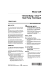
3. Remove and discard the red wire between the
transformer and the old control board, designs A-B
See figure 1 page 3.
(b) Units falling between date codes 96050076 and
98020066 containing a post purge (delay off) fan relay
will need the defrost heater relay added. Refer to wiring
diagram on page (4).
4. For unit design B requiring the additional relay, find a
suitable location and mount the relay with the screws
~rovided.
(c) Units falling after date code 98020066 refer to wiring
diagram in the unit. See figure 2
5. Reach behind the control box and cut the sensor
wires that are molded into the old defrost board
(2 blue and 1 white12 red and 1 white) and pull those
wires out. Disconnect the remaining leads from the
old defrost control. These leads are indicated as
broken lines in figure 1. Remove old control.
6. Mount the new defrost control in the exact location
the old one was removed from.
7. Bring the two leads of the new defrost sensor into
the control box. Connect one of the leads to the 24
volt terminal of the transformer and connect the other
lead to the new defrost control at one of the
terminals labeled 24VAC.
8. Reconnect the leads disconnected in step 5 to the
new control. Note: The old control has two common
terminals whereas the new control has one. The two
commons must be tied together or the reversing
valve common will need to be relocated.
9. Units requiring the additional relay will wire as
follows:
a. remove the brown wire from pin # 3 of the
defrost relay and move it to pin # 3 of the defrost
heater relay.
b. using one of the new wires, connect one end
to pin # 1 of the defrost heater relay and the other
end to the hold terminal of the new defrost control.
c. with another new wire, place one end on pin # 3
of the defrost relay, and the other end of this wire on
coil terminal (A) of the defrost heater relay.
d. place one end of the third and final wire on coil
terminal (B) of the defrost heater relay, and the other
end of this wire on transformer common.
10. Refer to figure (4) for proper location of the defrost
sensor according to unit model # and coil design.
Secure the sensor to the U-Bend with one of the tie
wraps provided. Wrap the sensor with the piece of
presstite provided to prevent the sensor from being
influenced by surrounding air temperatures.
11. Check the new control's run time jumper.
Recommended setting is (60) minutes.
12. Test the defrost control as follows:
a. place a jumper from transformer 24VAC to the
24VAC terminal at the control board to simulate
closed contacts.
b. with the unit running in the heat mode, short
the test pins until a click is heard, remove the short
immediately. Outdoor fan should shut off, reversing
valve should switch, and heater contactor(s) should
engage.
c. turn off the unit and remove the test jumper
from the 24VAC terminals
13. Affix these instructions close to the unit for future
reference.
14. Design A units refer to figure 3 for wire diagram
IF YOU HAVE ANY QUESTIONS
REGUARDING THESE SERVICE
INSTRUCTIONS OR NEED
TECHNICAL ASSISTANCE PLEASE
CALL TOLL FREE 1-800-807-7066
extension 3
I
I
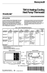
Fiaure 2
INSIDER and VERT-I-PAK B Series
®
®
Service Manual
INVBSVC (03/02)
Table of Contents
Introduction ............................................
Model Number Identification Guide ........
Serial Number Identification Guide .........
General Description ...............................
Refrigerant System Operation ................
Sequence of Operation ..........................
Air Circulation .........................................
Cooling ...................................................
Heating ...................................................
Defrost ...................................................
Emergency Heat ....................................
Electrical Supply .....................................
Supply Circuit .........................................
Supply Voltage .......................................
Control Wiring ........................................
Electrical Ground ....................................
Room Thermostats ................................
Location .................................................
Heat Anticipators ....................................
Setting the Heat Anticipator ....................
Electric Strip Heaters .............................
Indoor Blower – Air Flow ........................
Blower Wheel Inspection ........................
Cooling ...................................................
External Static Pressure .........................
Checking External Static Pressure .........
Checking Approximate Airflow ...............
Electric Heat Strips .................................
Condenser Fan Motors ..........................
Capacitors ..............................................
Capacitor Check With Capacitor Analyzer
Capacitor Connections ...........................
Compressors .........................................
Operating Noise Level ............................
Compressor Contactor ...........................
Anti-cycle Timer .....................................
Defrost ...................................................
2
3
4
4
5
6
7
7
7
7
7
7
8
8
8
8
8
9
9
9
10-11
12
12
12
12
12
12-13
13
13
13
13
13
13
14
14
14
15
15
Defrost Control Operation ......................
Testing Defrost Mode Of Operation ........
Troubleshooting .....................................
High Pressure Switch .............................
Low Pressure Switch ..............................
Compressor Checks ..............................
Locked Rotor Voltage (L.R.V.) Test ........
Single Phase Connections .....................
Determine L.R.V. ...................................
Amperage (L.R.A.) Test..........................
Single Phase Running and L.R.A. Test ..
Internal Overload ....................................
Checking the Internal Overload ..............
Single Phase Resistance Test ................
Procedure for Compressor Replacement
Expansion Valves ...................................
Refrigerant Charging ..............................
Method of Charging ................................
Subcooling Method ................................
Reversing Valve Description/Operation ..
Electrical Circuit and Coil .......................
Testing Coil ............................................
Checking the Reversing Valve ................
Procedure for Changing Reversing Valve
INSIDER Chassis Specifications ............
B-Series Chassis Specification ..............
Wiring Diagram Index ............................
All Standard Air Conditioners Wiring Diagram
Air Conditioners with Water Coil .............
All Standard Heat Pump Wiring Diagram
Frost Free Heat Pump Wiring Diagrams
Time Delay Relay Wiring Diagram .........
Troubleshooting Chart Cooling Mode .....
Troubleshooting Chart Heating Mode .....
Refrigerant System Diagnosis Cooling ..
Refrigerant System Diagnosis Heating ..
15
16-17
17
17
17-18
18
18
18
18
18
18
18
18
19
19
19
19
19-20
20
20
21
21
21
21-22
22
23
24
56
67
78
28-29
30
31
32
33
34
Introduction
This service manual is designed to be used in conjunction with the installation manuals provided with
each air conditioning system component. Air conditioning systems consist of BOTH an evaporator
(indoor section) and a condenser (outdoor section) in one closed system, and a room thermostat.
Electric strip heaters are also considered part of the system.
This service manual was written to assist the professional HVAC service technician to quickly and
accurately diagnose and repair any malfunctions of this product.
IMPORTANT: It will be necessary for you to accurately identify the unit you are
servicing, so you can be certain of a proper diagnosis and repair. (See Unit
Identification.)
The information contained in this manual is intended for use by a qualified service technician who is
familiar with the safety procedures required in installation and repair, and who is equipped with the
proper tools and test instruments.
Installation or repairs made by unqualified persons can result in hazards subjecting the unqualified person
making such repairs to the risk of injury or electrical shock which can be serious or even fatal not only to
them, but also to persons being served by the equipment.
If you install or perform service on equipment, you must assume responsibility for any bodily injury or
property damage which may result to you or others. Friedrich Air Conditioning Company will not be
responsible for any injury or property damage arising from improper installation, service, and/or service
procedures.
3
Model Number Identification Guide
MODEL NUMBER
––––– C D H
P 18 B 05 0 A
C = Standard Efficiency
E = High Efficiency
DESIGN SERIES
FILTER TYPE
0 = Front grille w/filter CDHP models
1 = No grille, drop-in rack w/filter
2 = Left side RA duct w/o filter
3 = Front RA duct w/o filter
D = Down Flow
U = Up Flow
AC = Air Conditioning
H = Heat Pump
ELECTRIC HEATER SIZE
(Nominal KW size)
05 = 5.0 KW
10 = 10.0 KW
15 = 15.0KW
Series P – B
NOMINAL CAPACITY (BTUh)
18 = 18,000 22 = 22,000 24 = 24,000
25 = 25,000 29 = 29,000 35 = 35,000
36 = 36,000 48 = 48,000
VOLTAGE
B = 208/230V - 1Ph - 60 Hz Active Defrost
E = 208/230V - 1 Ph - 60 Hz Passive Defrost
Model Number Identification Guide
MODEL NUMBER ———
V
E
B
24 K 10 RT A
V = Vertical Series
E = Cooling with or without electric heat
H = Heat Pump
ENGINEERING CODE
DEFROST TYPE
RT = Active Defrost
FF = Passive Defrost
DESIGN SERIES
NOMINAL CAPACITY (BTUh)
24= 24,000 30 = 30,000 36 = 36,000
42 = 42,000 48 = 48,000 60 =60,000
ELECTRIC HEATER SIZE
(Nominal KW size)
05 = 5.0 KW
20 = 20,000 KW
10 = 10.0 KW 25 = 25,000 KW
15 = 15.0 KW
VOLTAGE
K = 208/230V - 1Ph. - 60Hz.
Serial Number Identification Guide
SERIAL NUMBER
01
01
00001
PRODUCTION RUN NUMBER
Year Manufactured
4
Month Manufactured
01 = Jan
04 = Apr
02 = Feb
05 = May
03 = Mar
06 = Jun
07 = Jul
08 = Aug
09 =Sep
10 = Oct
11 = Nov
12 = Dec
GENERAL DESCRIPTION
INSIDER and VERT-I-PAK B Series models are self-contained indoor heating and cooling systems. This means that all of
the components for heating and cooling are in a single package.
INSIDER and VERT-I-PAK B Series units are manufactured as air conditioners with electric heat as well as heat pumps.
These units are very similar to their heat pump counterparts with the main difference being in the control box components
and the air conditioners do not have reversing valves. Basically everything else is the same. The cabinets are the same, the
major components are the same, as is their general locations in the cabinet.
B-SERIES VERT-I-PAK® UPFLOW MODELS
INSIDER DOWNFLOW MODELS
5
REFRIGERANT SYSTEM OPERATION
A good understanding of the basic operation of the
refrigeration system is essential for the service technician.
Without this understanding, accurate troubleshooting of
refrigeration system problems will be more difficult and time
consuming, if not (in some cases) entirely impossible. The
refrigeration system uses four basic principles (laws) in its
operation they are as follows:
1.
"Heat always flows from a warmer body to a cooler
body."
2.
"Heat must be added to or removed from a substance
before a change in state can occur."
3.
"Flow is always from a higher pressure area to a
lower pressure area."
4.
"The temperature at which a liquid or gas changes
state is dependent upon the pressure."
The refrigeration cycle begins at the compressor. Starting
the compressor creates a low pressure in the suction line
which draws refrigerant gas (vapor) into the compressor. The
compressor then "compresses" this refrigerant, raising its
pressure and its (heat intensity) temperature.
The refrigerant leaves the compressor through the discharge
line as a HOT high pressure gas (vapor). The refrigerant
enters the condenser coil where it gives up some of its heat.
The condenser fan moving air across the coil's finned surface
facilitates the transfer of heat from the refrigerant to the
relatively cooler outdoor air.
When a sufficient quantity of heat has been removed from
the refrigerant gas (vapor), the refrigerant will "condense"
(i.e. change to a liquid). Once the refrigerant has been
condensed (changed) to a liquid it is cooled even further by
the air that continues to flow across the condenser coil.
The system design determines at exactly what point (in the
condenser) the change of state (i.e. gas to a liquid) takes
place. In all cases, however, the refrigerant must be totally
condensed (changed) to a liquid before leaving the condenser
coil.
6
The refrigerant leaves the condenser coil through the liquid
line as a WARM high pressure liquid. It next will pass through
the refrigerant drier (if so equipped). It is the function of the
drier to trap any moisture present in the system,
contaminants, and LARGE particulate matter.
The liquid refrigerant next enters the metering device. The
metering device is a TXV. The purpose of the metering device
is to "meter" (i.e. control or measure) the quantity of
refrigerant entering the evaporator coil.
Since the evaporator coil is under a lower pressure (due to
the suction created by the compressor) than the liquid line,
the liquid refrigerant leaves the metering device entering the
evaporator coil. As it enters the evaporator coil, a larger
area and lower pressure allows the refrigerant to expand
and lower its temperature (heat intensity.) This expansion
is often referred to as "boiling." Since the units blower is
moving indoor air across the finned surface of the evaporator
coil, the expanding refrigerant absorbs some of that heat.
This results in a lowering of the indoor air temperature, hence
the "cooling" effect.
The expansion and absorbing of heat cause the liquid
refrigerant to evaporate (i.e. change to a gas). Once the
refrigerant has been evaporated, it is heated even further by
the air that continues to flow across the evaporator coil.
The particular system design determines at exactly what
point (in the evaporator) the change of state (i.e. liquid to
gas) takes place. In all cases, the refrigerant must be totally
evaporated (changed) to a gas before leaving the evaporator
coil.
The low pressure (suction) created by the compressor
causes the refrigerant to leave the evaporator through the
suction line as a COOL low pressure vapor. The refrigerant
then returns to the compressor, where the cycle is repeated.
SEQUENCE OF OPERATION
Air Circulation
Defrost
When the thermostat is set with the FAN switch set to ON
and the SYSTEM switch is set to OFF, the heat pump is in
air circulation mode. While the thermostat is set this way a
24 volt signal is on the "G" thermostat terminal, energizing
the blower control, turning on the indoor-air blower. The
blower will run continuously until the setting is changed.
A drop in room temperature will break the 24-volt signal on
the "Y" thermostat terminal de-energizing the compressor
contactor turning off the compressor and outdoor air blower.
It also causes the loss of the 24-volt signal on the "G"
thermostat terminal starting the timer of the post purge
control (60-second delay) to turn off the indoor air blower.
During normal operation in the heating mode, frost & ice
may build up on the outdoor coil. This frost & ice must be
removed periodically for the unit to operate properly. The
INSIDER & VERT-I-PAK units employ either an active or a
passive defrost method to accomplish this. To identify which
method your unit employs, Check the Model Number
Identification Guides located at the beginning of this manual.
Active Defrost
An active defrost cycle is initiated by the defrost control
when the combination of the selected compressor run time
and an outdoor coil temperature of 33 degrees, + or – 3
degrees is reached. When this occurs:
The defrost relay is energized.
● Contacts 4 & 5 open, de-energizing the outdoor blower.
● Contacts 4 & 6 close, energizing the drain line heater,
(if equipped.)
● Contacts 1 & 2 open, de-energizing the reversing valve
solenoid.
● Contacts 1 & 3 close, energizing the defrost heater
relay which energizes the electric heat strip/strips.
When the outdoor coil temperature reaches 53 degrees, +
or – 5. 5 degrees, or 10 minutes passes, the defrost control
will terminate the defrost cycle, reversing the above actions
and returning the unit to normal heat pump mode operation.
Heating
Passive Defrost
With the thermostat set to heating mode (SYSTEM switch
set to HEAT and FAN switch set to AUTO) a drop in the
room temperature will make a 24-volt signal on the "G"
thermostat terminal to the post purge control turning on the
indoor air blower. It also makes a 24-volt signal on the "Y"
thermostat terminal through the high-pressure switch and
low pressure switch energizing the compressor contactor
turning on the compressor and outdoor air blower. The
reversing valve solenoid coil will be energized through the
"B" terminal when the thermostat is set to the heat position.
A passive defrost cycle is initiated when the outdoor coil
temperature falls to 33 degrees, + or – 3 degrees. The
frost-free thermostat is responsible for determining this
temperature. It not only senses the outdoor coil refrigerant
temperature, it senses the outdoor entering air temperature
as well. When this occurs:
Cooling
When thermostat is set for cooling mode (SYSTEM switch
set to COOL and FAN switch set to AUTO) a rise in room
temperature will make a 24-volt signal on the "G" thermostat
terminal to the post purge control turning on the indoor air
blower. It also causes a 24-volt signal on the "Y" thermostat
conductor to the high and low pressure switches energizing
the compressor contactor turning on the compressor and
outdoor air blower.
A further drop in the room temperature will make a 24-volt
signal through the "W" thermostat terminal energizing the
electric heat contactor, bringing on the auxiliary electric heat.
A rise in the room temperature will break the 24-volt signal
on the "W" thermostat terminal de-energizing the electric
heat contactor, turning off the auxiliary electric heat.
A further rise in room temperature will break the 24-volt signal
on the "G" thermostat conductor starting the timer of the
post purge control (60 second delay) to turn off the indoorair blower. It also causes the loss of the 24-volt signal on
the "Y" thermostat conductor de-energizing the compressor
contactor turning off the compressor and outdoor air blower.
●
●
●
●
The frost-free thermostat closes, energizing the frost
free relay coil.
Contacts 4 & 5 open, de-energizing the reversing valve
solenoid.
Contacts 1 & 2 open, de-energizing the compressor
contactor coil.
Contacts 1 & 3 close, energizing the electric heater
contactor coil when the room thermostat calls for heat.
When the room thermostat calls for heating, the unit will
now supply heat only by means of the electric strip heaters.
The compressor will remain locked out until the outdoor coil
temperature rises to 53 degrees, + or –5. 5 degrees. When
the above temperature is reached, the frost-free thermostat
opens, reversing the above actions and returning the unit to
normal heat pump mode operation.
7
Emergency Heat
Supply Circuit
The EM HEAT setting provides for the use of the electric
auxiliary heat in the event of a malfunction of the heat pump
system.
NOTE: For economical reasons, the EM HEAT mode should
only be used when necessary.
With the thermostat set on EM HEAT or EMER, and the
FAN switch set on AUTO, a drop in room temperature causes
the upper mercury switch to make a 24-volt signal on the
"G" thermostat conductor, energizing the indoor blower post
purge control, and turning on the indoor air blower. It also
causes a 24-volt signal on the "W" thermostat terminal
energizing the electric heat contactor (s) turning on the
electric heat.
A rise in room temperature causes the upper mercury switch
to break the 24-volt signal on the "G" thermostat conductor
starting the timer of the post purge control (60-second delay)
to turn off the indoor air blower. It also causes the loss of
the 24-volt signal on the "W" thermostat terminal deenergizing the electric heat contactor (s) turning off the electric
heat.
The system cannot be expected to operate correctly unless
the system is properly connected (wired) to an adequately
sized single branch circuit. Check the installation manual
and/or technical data for your particular unit and/or strip
heaters to determine if the circuit is adequately sized.
WARNING:
Electrical shock hazard.
Turn OFF electric power at fuse box or service panel before
making any electrical connections and ensure a proper
ground connection is made before connecting line voltage.
Failure to do so can result in property damage personal
injury and/or death.
To insure proper operation, supply voltage to the system
should be within five (5) percent (plus or minus) of listed
rating plate voltage. Supply voltage to the unit should be a
nominal 208/230 volts. It must be between 197 volts and
253 volts. Supply voltage to the unit should be checked
WITH THE UNIT IN OPERATION. Voltage readings outside
the specified range can be expected to cause operating
problems. Their cause MUST be investigated and corrected.
Control (Low) Voltage
To insure proper system operation the transformer secondary
output must be maintained at a nominal 24 volts. The control
(low) voltage transformer is equipped with multiple primary
voltage taps. Connecting the primary, (supply) wire to the
tap (i.e., 208 and 240 volts) that most closely matches the
MEASURED supply voltage will insure proper transformer
secondary output is maintained.
Electrical Ground
Grounding of the electrical supply to ALL UNITS IS
REQUIRED for safety reasons.
CONTROL WIRING
LOW VOLTAGE TERMINAL
DESIGNATION
1F59 THERMOSTAT
1F59
THERMOSTAT
Terminals O, L, and E are not used.
8
VOLTAGE TERMINAL BLOCK
Electrical Supply
Supply voltage
Room Thermostats
Room thermostats are available from several different
manufacturers in a wide variety of styles. They range from
the very simple bimetallic type to the complex electronic
set-back type. In all cases, no matter how simple or complex,
they are simply a switch (or series of switches) designed to
turn equipment (or components) "ON" or "OFF" at the desired
conditions.
Thermostat Location
An improperly operating, or poorly located room thermostat
can be the source of perceived equipment problems. A careful
check of the thermostat and wiring must be made to insure
that it is not the source of problems.
Location
The thermostat should not be mounted where it may be
affected by drafts, discharge air from registers (hot or cold),
or heat radiated from the sun or appliances.
The thermostat should be located about 5 Ft. above the
floor in an area of average temperature, with good air
circulation. Close proximity to the return air grille is the best
choice.
Mercury bulb type thermostats MUST be level to control
temperature accurately to the desired set-point. Electronic
digital type thermostats SHOULD be level for aesthetics.
Measuring Current Draw
Heat Anticipators
Heat anticipators are small resistance heaters (wired in
SERIES with the "W" circuit) and built into most
electromechanical thermostats. Their purpose is to prevent
wide swings in room temperature during system operation
in the HEATING mode. Since they are wired in series, the
"W" circuit will open if one burns out preventing heat operation.
The heat anticipator provides a small amount of heat to the
thermostat causing it to cycle (turn off) the heat source just
prior to reaching the set point of the thermostat. This prevents
exceeding the set point.
In order to accomplish this, the heat output from the
anticipator must be the same regardless of the current flowing
through it. Consequently, some thermostats have an
adjustment to compensate for varying current draw in the
thermostat circuits.
The proper setting of heat anticipators then is important to
insure proper temperature control and customer satisfaction.
A Heat anticipator that is set too low will cause the heat
source to cycle prematurely possibly never reaching set
point. A heat anticipator that is set too high will cause the
heat source to cycle too late over shooting the set point.
9
Setting the Heat Anticipator
The best method to obtain the required setting for the heat
anticipator, is to measure the actual current draw in the
control circuit (“W”) using a low range (0-2.0 Amps) Ammeter.
After measuring the current draw, simply set heat anticipator
to match that value.
If a low range ammeter is not available, a "Clamp-on" type
ammeter may be used as follows:
1. Wrap EXACTLY ten (10) turns of wire around the jaws
of a clamp-on type ammeter.
2. Connect one end of the wire to the "W" terminal of the
thermostat subbase, and the other to the "R" terminal.
3. Turn the power on, and wait approximately one minute,
then read meter.
4. Divide the meter reading by 10 to obtain the correct
anticipator setting. If an ammeter is not available, set
the heat anticipator as shown below.
The Anticipation Setting
for the 5 and 10 Kw is 0.3
10
The Honeywell T841A was the primary thermostat provided
and used with the INSIDER heat pump prior to January 1999.
The T841A is a heat pump thermostat with one stage of
cooling and two stages of heat. This thermostat has two
mercury bulbs making accurate leveling a requirement for
proper operation.
The Anticipation Setting
for the 15 KW is 0.6.
In April 2000, the White Rogers 1F59-13 became the primary
thermostat provided and used with the INSIDER and VERTI-PAK B Series heat pump. The 1F59-13 is an electronic
heat pump thermostat providing control without mercury
bulbs. The electronic digital type thermostat should be
leveled for aesthetics.
Table 1 – First Stage Heat and Cool
Anticipation
Reference
Number
10
14
16
30
Approx.
Temperature
Differential
0.8°F
1.1°F
1.3°F
2.4°F
Table 2 – Second Stage and Emergency
Heat
Anticipation
Reference
Number
10
14
16
30
White Rodgers 1F59-13
The White Rodgers thermostat has switches that control
the anticipation setting. The following illustrations and tables
show the location of the switches and setting information.
Approx.
Temperature
Differential
0.3°F
1.4°0F
1.5°F
2.9°F
The CM260 is a basic heat-cool thermostat with a set of
mechanical contacts operated by a bimetal coil. Accurate
leveling is not a requirement for proper operation of this
thermostat. The thermostat controls are described below.
Terminal and Switch Location
Robert Shaw CM 260
Anticipation Selection Switch Settings
CAUTION: Recheck the wiring to be certain
proper terminals are connected before
applying power. Improper wiring or
installation may damage the thermostat.
11
Electric Strip Heaters
Electric heat strips use electrical resistance to produce heat.
They normally use coils of nichrome wire to provide the
resistance. When electrical current flows through the coils,
the resistance of the coil produces a specific amount of
heat. Proper airflow across strip heaters is essential to
insure proper operation, and life expectancy. During operation,
the elements will produce a dull orange glow. Insufficient
airflow will cause elements to overheat (producing a very
bright orange glow) and cycle on limit switch, or possibly
fail.
Heaters are available in several sizes (wattage). Normally,
heaters larger then 10 KW (10 kilowatts) are divided into
increments with one or two increments (i.e. 5 or 10 KW)
controlled by a single relay which energizes a contactor.
Strip heaters may be checked using one of several methods.
During operation ("Calling for Heat"), a clamp-on ammeter
may be used to check the current draw of each individual
increment to verify its operation. At 240 Volts (nominal), a
current draw of approximately 20 Amps should be indicated
for each 5 KW. If no current draw is indicated, the heater is
not operating. This may be due to defective relay or contactor,
an open (broken) element, tripped (open) breaker, etc. These
conditions then, may be checked (with the power "OFF")
using an ohmmeter. They may also be checked (being very
careful) with the power "ON" by using a voltmeter.
External Static Pressure
External Static Pressure can best be defined as the pressure
difference (drop) between the Positive Pressure (discharge)
and the Negative Pressure (intake) sides of the blower.
External Static Pressure is developed by the blower as a
result of resistance to airflow (Friction) in the air distribution
system EXTERNAL to the INSIDER / VERT-I-PAK B Series
cabinet.
Resistance applied externally to the INSIDER and VERT-IPAK B Series (i.e. duct work, coils, filters, etc.) on either
the supply or return side of the system causes an INCREASE
in External Static Pressure accompanied by a REDUCTION
in airflow.
External Static Pressure is affected by two (2) factors.
1. Resistance to Airflow as already explained.
2. Blower Speed. Changing to a higher or lower blower
speed will raise or lower the External Static Pressure
accordingly.
These affects must be understood and taken into
consideration when checking External Static Pressure/Airflow
to insure that the system is operating within design
conditions.
All component parts of strip heater assemblies are field
replaceable. If the entire heater package is removed for
servicing, (i.e. component replacement), extreme care should
be used when reinstalling the heater package that all wiring
is properly connected.
Operating a system with insufficient or excessive airflow
can cause a variety of different operating problems. Among
these are reduced capacity, freezing evaporator coils,
premature compressor and/or heating component failures.
etc.
Indoor Blower – Air Flow
System airflow should always be verified upon completion
of a new installation, or before a change-out, compressor
replacement, or in the case of heat strip failure to insure
that the failure was not caused by improper airflow.
INSIDER and VERT-I-PAK B-Series units use a single-speed
permanent split capacitor motor direct drive. Different size
(HP) motors and/or different diameter blower wheels are used
in different models to obtain the required airflow.
Blower Wheel Inspection
Visually inspect the blower wheel for the accumulation of
dirt or lint since they can cause reduced airflow. Clean the
blower wheel of these accumulations. If accumulation cannot
be removed, it will be necessary to remove the blower
assembly from the unit for proper wheel cleaning.
Cooling
A nominal 400 (350-450 allowable) CFM per ton of airflow is
required to insure proper system operation, capacity, and
efficiency. Factory blower motors should provide the proper
airflow for the size (cooling capacity) of the unit when
connected to a properly sized duct system.
Checking External Static Pressure
The airflow through the unit can be determined by measuring
the external static pressure of the system, and consulting
the blower performance data for the specific INSIDER and
VERT-I-PAK B Series unit.
1. Set up to measure external static pressure at the supply
and return air.
2. Drill holes in the supply duct for pressure taps, pilot
tubes or other accurate pressure sensing devices.
3. Connect these taps to a level inclined manometer or
Magnehelic gauges.
4. Ensure the coil and filter are clean, and that all the
registers are open.
5. Determine the external static pressure with the blower
operating.
12
6. Refer to the Air Flow Data for your system to find the
actual airflow.
Condenser Fan Motors
7. If the actual airflow is either too high or too low, check
the ductwork and make appropriate changes
The INSIDER / VERT-I-PAK B Series units use a single
speed permanent split capacitor motor direct drive. Different
size HP motors and/ or wheels are used on different models
to obtain the required heat transfer.
EXAMPLE: Airflow requirements are calculated as follows:
1 ½ TON SYSTEM ( 18,000 Btu)
Operating to full capacity @ 230 volts with dry coil
measured external static pressure .20
Air Flow = 500 CFM
It is also important to remember that when dealing with
INSIDER and VERT-I-PAK B Series units that the measured
External Static Pressure increases as the resistance is
added externally to the cabinet. Example: duct work, dirty
filters, grilles.
Checking Approximate Airflow
If an inclined manometer or Magnehelic gauge is not available
to check the External Static Pressure, or the blower
performance data is unavailable for your unit, approximate
air flow call be calculated by measuring the temperature
rise, then using the following criteria.
Electric Heat Strips
The approximate CFM actually being delivered can be
calculated by using the following formula:
KILOWATTS X 3413
Temp Rise X 1.08
Many motor capacitors are internally fused. Shorting the
terminals will blow the fuse, ruining the capacitor. A 20,000
ohm 2 watt resistor can be used to discharge capacitors
safely. Remove wires from capacitor and place resistor
across terminals.
Capacitor Check With Capacitor Analyzer
The capacitor analyzer will show whether the capacitor is
"open" or "shorted." It will tell whether the capacitor is within
its microfarads rating and it will show whether the capacitor
is operating at the proper power-factor percentage. The
instrument will automatically discharge the capacitor when
the test switch is released.
WARNING
HAZARD OF SHOCK AND ELECTROCUTION. A
CAPACITOR CAN HOLD A CHARGE FOR LONG
PERIODS OF TIME. A SERVICE TECHNICIAN WHO
TOUCHES THESE TERMINALS CAN BE INJURED.
NEVER DISCHARGE THE CAPACITOR BY SHORTING
ACROSS THE TERMINALS WITH A SCREWDRIVER.
Capacitor Connections
DO NOT simply use the Kilowatt Rating of the heater (i.e.
5.0, 10.0, 15.0 etc.) as this will result in a less-than-correct
airflow calculation. Kilowatts may be calculated by
multiplying the measured voltage to the unit (heater) times
the measured current draw of all heaters (ONLY) in operation
to obtain watts. Kilowatts are than obtained by dividing by
1000.
EXAMPLE: Measured voltage to unit (heaters) is 230
volts. Measured Current Draw of strip heaters is 20.0
amps.
230 X 20.0 = 4600
4600/1000 = 4.6 Kilowatts
4.6 x 3413 = 15700
Supply Air
Return Air
Temperature Rise
Capacitors
95°F
75°F
20°
The starting winding of a motor can be damaged by a shorted
and grounded running capacitor. This damage usually can
be avoided by proper connection of the running capacitor
terminals. From the supply line on a typical 230 volt circuit,
a 115 volt potential exists from the "R" terminal to ground
through a possible short in the capacitor. However, from the
"S" or start terminal, a much higher potential, possibly as
high as 400 volts, exists because of the counter EMF
generated in the start winding. Therefore, the possibility of
capacitor failure is much greater when the identified terminal
is connected to the “S" or start terminal. The identified
terminal should always be connected to the supply line, or
"R" terminal, never to the "S" terminal.
When connected properly, a shorted or grounded
running-capacitor will result in a direct short to ground from
the "R" terminal and will blow the line fuse. The motor
protector will protect the main winding from excessive
temperature.
20 X 1.08 = 21.6
15700 = 727 CFM
21.6
13
Compressors
The type of compressor used is the SCROLL compressor.
The Scroll compressor may easily be distinguished from a
a reciprocating compressor by its relatively tall, and relatively
small diameter round case. Although the methods of testing
and/or checkout of both types of compressors is essentially
the same, the Scroll compressor differs from the reciprocating
type compressor in several ways.
First, the Scroll compressor uses a pair of Scrolls (one
stationary, one "orbiting") to compress and pump refrigerant
through the system, instead of the piston and valve
arrangement found in a reciprocating compressor. This
design makes the Scroll compressor able to tolerate a certain
amount of liquid refrigerant better than a reciprocating
compressor. Consequently, crankcase heaters are not
normally required on most scroll equipped models.
Electrical Shock Hazard.
Disconnect power at fuse box or service panel
before performing any service on the unit.
Failure to follow this warning can result in property
damage, personal injury, and/or death.
The contactor coil is energized on a call for COOLING AND
HEATING from the room thermostat. If the contactor is not
being energized (Pulled-In) it may be checked as follows:
A check across the two (2) coil terminals of the contactor
should indicate 24 Volts during a call for COOLING and
HEATING. If 24 volts IS indicated, and the contactor does
not pull-In, the contactor is faulty (either a bad coil or
mechanically stuck).
Coil
Coil
Scroll Compressor
Typical Double Pole Contactor
Operating Noise Level
The operating noise characteristics of a scroll compressor
also differ considerably from that of a reciprocating
compressor. If you are unfamiliar with the operating noise
characteristics of a scroll compressor, you should be
absolutely certain that there is a problem with the
compressor prior to replacing it. For example, a scroll
compressor which is running in reverse rotation (see anticycle timer section on page 15) will apparently make an
excessive amount of noise.
Compressor Contactor
The compressor contactor is a "Normally Open" Double Pole
(Relay) which when energized closes to complete the line
voltage circuit to the compressor and outdoor fan motor.
14
If 24 volts is NOT indicated, check any optional controls
(i.e. High Pressure or Low Pressure Switches) which may
be wired in series with the compressor contactor. Next check
across "Y" and "C" of the units Low voltage (Control) circuit
during a call for COOLING or HEATING. This should also
indicate 24 volts. If not, there may be problems with the
thermostat, control wiring, or the Low (control) voltage
transformer.
Problems with the transformer can quickly be ruled out by
jumpering between "R" & "G" of the units low (control) voltage
circuit (or switching the FAN switch on the thermostat
subbase from AUTO to "ON.")
Once the transformer has been determined to be good, a
jumper placed between "R" and "Y" of the INDOOR units
low (control) voltage circuit should cause the contactor coil
to be energized. If so, the problem is in the thermostat or
thermostat wiring. If not, the problem is in the wiring between
the Low (Control) voltage terminal block and the contactor.
When operating the heat pump in 1st Stage Heating,
refrigerant flow (discharge gas) is being directed (by the
reversing valve) to the INDOOR coil, making it the
CONDENSER. Consequently, the OUTDOOR coil is then
acting as the EVAPORATOR.
Operating an evaporator coil in low outdoor ambient
temperatures (such as would be present when heating is
required) will cause the EVAPORATOR (outdoor coil) to
develop frost. Left unchecked, the frost would continue to
build to the point of totally blocking the coil, severely reducing
heat transfer, and consequently; the heating capacity of the
unit.
Anti-cycle Timer
Anti-cycle Timer
(Scroll Compressor Models)
Some older models are equipped with an electronic AntiCycle timer. This timer is required to prevent the possibility
of the scroll compressor running in reverse rotation due to a
momentary power interruption. The anti-cycle timer is
essentially a "delay on break" timer which prevents the
compressor contactor from reenergizing for a period of 5
minutes if the power to it is interrupted. This delay provides
sufficient time for the compressor to come to a complete
stop before being reenergized, preventing the compressor
from starting in reverse rotation. If defective, however, it will
not complete the circuit to the compressor contactor. The
anti-cycle timer is not used on new INSIDER / Vert-Pak "B"
units. The IF59-13 thermostat has a built in anti cycle
feature.
Defrost
Typical
Defrost Control Board
To insure that this does not happen, some means of
"Defrosting" the unit is required. All INSIDER and VERT-IPAK B units use either an active defrost or passive defrost
design. Check the Model Number Guide to identify which
design you are working with.
Typical Defrost Sensor
15
Defrost Control Operation (Active Defrost)
An Electromechanical Defrost (Coil Temperature) Sensor
is used with all of the various defrost controls. This sensor
is a "Normally Open" switch wired in series with either the
"R" terminal or the "C" terminal.
The sensor closes when (coil) temperature conditions have
been met. When closed, the sensor completes a circuit to
components within the control (board) itself which then
begins "Accumulating" (keeping track of) compressor run
time. Consequently, if the sensor NEVER closes, the unit
will NEVER Defrost.
Defrost intervals (frequency) are field selectable (30, 60, or
90 Minutes). The frequency may be changed by moving
(positioning) the jumper (or shunt) to a different terminal.,
i.e. 30 minutes, 60 minutes, and 90 minutes. Defrost
intervals should be set to the LONGEST interval that will
still allow the coil to completely defrost during one defrost
cycle.
With the desired defrost interval selected, the control will
initiate a defrost cycle whenever it "ACCUMULATES" this
amount of compressor run time. The defrost (coil temp.)
sensor MUST remain closed during this accumulation
Period. If the defrost sensor opens at any time during the
accumulation period (such as may happen during an "OFF"
cycle in mild weather), the "ACCUMULATED" time will be
lost (i.e. counter is reset to zero).
An automatic defrost capability is provided in the system
that will defrost the outdoor air coil when needed. The defrost
cycle is controlled by an ICM-300 time-temperature control.
(As described on Page 7, Defrost.)
After the selected compressor run time is accumulated and
a coil temperature of 33° ± 3° degrees F is reached, the
Defrost Control initiates a defrost cycle by energizing the
Defrost Relay.
The normally closed Defrost Relay contacts 4-5 open turning
off the outdoor blower motor.
Relay contacts 1-2 open de-energizing the Reversing Valve
Solenoid.
The normally open Defrost Relay contacts 1-3 close,
energizing the Defrost Heater Relay, turning on the electric
heat.
After 10 minutes or a rise in coil temperature to 55 degrees
F, the defrost cycle will terminate.
When the defrost cycle is terminated the above actions are
reversed.
The control will then begin accumulating time when (if) the
sensor closes during the next run ("ON") cycle.
Once initiated, a defrost cycle may be terminated one of
two (2) different ways.
16
1. The first, or "Normal" termination is based on coil
temperature. When the defrost sensor reaches its
opening temperature (indicating a fully defrosted coil) it
will open, deselecting the circuits that caused the unit
to change over into the defrost mode of operation.
This causes the second stage heat to be deenergized,
the outdoor fan to be reenergized, and the reversing
valve to shift back into the HEATING position.
2. The second type of termination for a defrost is a "TIMED"
(forced) termination. In the event that the defrost sensor
DOES NOT open within 10 minutes the control will
terminate the defrost cycle and return to normal 1st
stage heating operation.
Some of the reasons which might cause the sensor
NOT to open during a normal defrost cycle are, defrost
interval set TOO LONG, refrigerant circuit problems (i.e.
under charge, restriction, etc.) or a sensor which is
mechanically stuck closed.
Testing Defrost Mode Of Operation (Active
Defrost
The basic procedure for testing ALL of the defrost controls
used in this series is nearly identical, with relatively few
variations/exceptions (as noted).
As previously stated, the defrost (Coil Temperature) sensor
MUST be closed BEFORE ANY UNIT can initiate a defrost
cycle. A closed defrost sensor can be simulated by
"jumpering" across the defrost sensor.
The exact terminal identification(s) and/or locations the defrost
(coil temp.) sensor is wired across may vary. Check the
wiring diagram for your particular unit to determine WHERE
to place the jumper.
Once the defrost sensor is closed the "Timing" function of
the board will begin, (Temperature first, THEN time) and a
defrost cycle will be initiated when the selected interval time
(i.e. 30, 60, or 90 minutes) has been reached.
Since it is undesirable to wait this amount of time to check
control operation an "ACCELERATOR" has been designed
into these controls to significantly reduce the defrost interval
time FOR TESTING PURPOSES ONLY.
Controls are equipped with a pair of terminals identified as
"TEST" (or TST) which when "jumpered" will accelerate the
selected defrost interval time.
The method of jumpering the test pins varies slightly however,
based on the particular control.
With the TEST ("TST") pins jumpered, (and if the defrost
sensor remains closed) the unit will go into the Defrost mode
of operation every 7, 14, or 21 seconds (depending upon
interval selected and/or type of (control). The unit will then
remain in defrost until the accelerated "TIMED" (forced)
termination period (2-3 seconds depending upon control) is
reached as long as the "jumper" remains in place, and the
defrost sensor remains closed (or jumped, out). EXTENDED
OPERATION IN THIS MODE IS NOT RECOMMENDED.
During defrost the reversing valve solenoid will be deenergized,
the outdoor fan motor will be de energized and indoor
supplemental (second stage) heat will normally be
energized. The identification of the terminal (on the control
board) used to accomplish these function varies, however,
with the particular control.
When the frost-free thermostat senses a rise in the
temperature of the outdoor coil to 53 degrees, + or – 5. 5
degrees, the passive defrost cycle is complete. The
compressor will now be able to run to provide heat to the
space.
Testing Defrost Operation (Passive Defrost)
By referring to the wiring diagram for your particular unit you
should be able to determine where (what terminal to check
to verify if the control is performing the necessary switching
functions. If the control performs the necessary switching
functions, the problem is NOT in the defrost control, it is
EXTERNAL to the control.
An electromechanical defrost (coil temperature) sensor is
used on ALL units. This sensor is a "NORMALLY OPEN"
electrical switch wired in series with the defrost control board.
Depending upon the particular model and/or control used, it
may be wired in series with either the "R" circuit or the "C"
circuit to the board.
The sensor CLOSES when its temperature drops below a
predetermined level, completing the circuit to the defrost
board to begin "ACCUMULATING" compressor run time. The
sensor OPENS during defrost at another predetermined level
to TERMINATE the defrost cycle. The sensor can also OPEN
during an "OFF" cycle in warmer outdoor ambient conditions,
which will RESET (zero out) any time that has been
accumulated on the defrost control board.
If the defrost sensor does NOT open and close, it must be
replaced. (The sensor is designed to close at 33° ± 3°
degrees F and open at 53°F ± 5°.) When replacing the
defrost sensor BE ABSOLUTELY CERTAIN to reinstall the
replacement sensor in the EXACT LOCATION of the removed
sensor. Failure to do so may create problems with improper
defrosting of the unit.
Passive Defrost
Units, which employ the Passive method for defrosting the
outdoor coil, depend upon the rising of the temperature of
the outdoor coil to do so. No heat is supplied by the unit to
remove the frost & ice.
When the frost-free thermostat senses a temperature of 33
degrees, + or – 3 degrees, the compressor is locked-out.
The outdoor fan continues to run, allowing outdoor air to
help speed the defrosting process. Keep in mind, however
that the colder the outdoor temperature is, the longer it will
take for frost and ice to melt from the outdoor coil.
The Frost-Free Thermostat is mounted to the outdoor coil.
It is a saddle type sensor, using a snap-type strap to secure
it to a return bend on the outdoor coil. The thermostat switch
contacts are normally open, and will close on a fall in
temperature.
Two leads are permanently connected to the thermostat.
One lead connects to the coil of the frost-free relay. On
earlier model units, the other lead connects to "R" on the
low voltage transformer. Later model units have this lead
connected to terminal # 4 on the frost-free relay.
Disconnect power to the unit. Keep in mind that more that
one disconnect may be required. Install a jumper between
the two leads of the frost-free thermostat. Restore power to
the unit.
The compressor should be locked-out. The electric strip
heaters should be energized if; the room thermostat is calling
for heating. Cycle the room thermostat to insure that the
electric strip heaters do come on and off with the action of
the thermostat. The compressor should not run during this
test. When complete, disconnect power to the unit and
remove the jumper.
If you encounter a unit where frost or ice is present on the
outdoor coil and the compressor is still running, perform
this simple test. Should the compressor lockout with the
jumper installed, replace the frost-free thermostat.
High Pressure Switch
INSIDER and VERT-I-PAK B Series units are equipped with
a high-pressure switch. The purpose of the high-pressure
switch is to prevent damage to the compressor, which may
occur as a result of operating under high discharge pressure
conditions. Some possible causes of high discharge include
condenser fan motor failure, excessive refrigerant charge,
air and non-condensables in refrigerant circuit, etc.
The high-pressure switch is a "Normally closed" pressure
operated switch (automatic reset) wired in series with the
compressor contactor. The switch will remain closed,
completing the circuit to the compressor contactor until the
discharge pressure rises above (a nominal) 450 +/- 10 psig.
At this point the switch will open, breaking the circuit to the
compressor contactor. The switch then will remain open
until the pressure drops to (a nominal) 300 +/- 20 psig, at
which time it will close again, (auto reset) completing the
circuit to the compressor contactor.
17
Low Pressure Switch
The low-pressure switch is a "Normally Open" pressure
operated switch (Automatic Reset) wired in series with the
compressor contactor. The switch closes at (a Nominal) 15
+/- 5 psig of pressure in the refrigerant system completing
the circuit to the compressor contactor. The switch will remain
closed until the system pressure drops below (a Nominal) 3
psig, at which time it will open, breaking the circuit to the
compressor contactor.
Select the proper amperage scale and clamp the meter
probe around the wire to the "C" terminal of the compressor.
Turn on the unit and read the running amperage on the meter.
If the compressor does not start, the reading will indicate
the locked rotor amperage (L.R.A.).
Internal Overload
Locked rotor voltage (L.R.V.) is the actual voltage available
at the compressor under a stalled condition.
The compressor is equipped with an internal overload which
senses both motor amperage and winding temperature. High
motor temperature or amperage heats the overload causing
it to open, breaking the common circuit within the
compressor. Heat generated within the compressor shell,
usually due to recycling of the motor, is slow to dissipate. It
may take anywhere from a few minutes to several hours for
the overload to reset.
Single Phase Connections
Checking the Internal Overload
Compressor Checks
Locked Rotor Voltage (L.R.V.) Test
Disconnect power from unit. Using a voltmeter, attach one
lead of the meter to the run "R" terminal on the compressor
and the other lead to the common "C" terminal of the
compressor. Restore power to unit.
CAUTION
Make sure that the ends of the lead do not touch the
compressor shell since this will cause a short circuit.
Determine L.R.V.
Start the compressor with the voltmeter attached; then stop
the unit. Attempt to restart the compressor within a couple
of seconds and immediately read the voltage on the meter.
The compressor under these conditions will not start and
will usually kick out on overload within a few seconds since
the pressures in the system will not have had time to
equalize. Voltage should be at or above minimum voltage of
197 VAC, as specified on the rating plate. If less than
minimum, check for cause of inadequate power supply; i.e.,
incorrect wire size, loose electrical connections, etc. The
compressor time delay relay will have to be bypassed for
this test. Do not leave the time delay bypassed when the
test is completed.
Amperage (L.R.V.) Test
The running amperage of the compressor is the most
important of these readings. A running amperage higher
than that indicated in the performance data indicates that a
problem exists mechanically or electrically.
Single Phase Running and L.R.A. Test
NOTE: Consult the specification and performance section
for running amperage. The L.R.A. can also be found on the
rating plate.
18
A reading of infinity (∞) between any two terminals MAY
indicate an open winding. If, however, a reading of infinity
(∞) is obtained between C & R and C & S, accompanied by
a resistance reading between S & R, an open internal
overload is indicated. Should you obtain this indication,
allow the compressor to cool (May take up to 24 hours)
then recheck before condemning the compressor. If an open
internal overload is indicated, the source of its opening must
be determined and corrected. Failure to do so will cause
repeat problems with an open overload and/or premature
compressor failure. Some possible causes of an open
internal overload include insufficient refrigerant charge,
restriction in the refrigerant circuit, and excessive current
draw.
Single Phase Resistance Test
Remove the leads from the compressor terminals and set
the ohmmeter on the lowest scale (R x 1).
Touch the leads of the ohmmeter from terminals common to
start ("C" to "S"). Next, touch the leads of the ohmmeter
from terminals common to run ("C" to "R").
Add values "C" to "S" and "C" to "R" together and check
resistance from start to run terminals ("S" to "R"). Resistance
"S" to "R" should equal the total of "C" to "S" and "C" to "R."
In a single phase PSC compressor motor, the highest value
will be from the start to the run connections (“S” to "R"). The
next highest resistance is from the start to the common
connections ("S" to "C"). The lowest resistance is from the
run to common. ("C" to "R".) Before replacing a compressor,
check to be sure it is defective.
Check the complete electrical system to the compressor
and compressor internal electrical system, check to be
certain that compressor is not out on internal overload.
Complete evaluation of the system must be made whenever
you suspect the compressor is defective. If the compressor
has been operating for sometime, a careful examination must
be made to determine why the compressor failed.
Recommended procedure for compressor
replacement
NOTE: Be sure power source is off, then disconnect all
wiring from the compressor.
1. Be certain to perform all necessary electrical and
refrigeration tests to be sure the compressor is actually
defective before replacing.
2. Recover all refrigerant from the system. PROPER
HANDLING OF RECOVERED REFRIGERANT
ACCORDING TO EPA REGULATIONS IS REQUIRED.
Do not use gauge manifold for this purpose if there has
been a burnout. You will contaminate your manifold and
hoses.
3. After all refrigerant has been recovered, disconnect
suction and discharge lines from the compressor and
remove compressor. Be certain to have both suction
and discharge access tubes open to atmosphere.
4. Carefully pour a small amount of oil from the suction
stub of the defective compressor into a clean container.
5. Using an acid test kit (one shot or conventional kit), test
the oil for acid content according to the instructions with
the kit.
6. If any evidence of a burnout is found, no matter how
slight, the system will need to be cleaned up following
proper procedures.
7. Install the replacement compressor.
8. Pressurize with a combination of R-22 and nitrogen and
leak test all connections with an electronic or Halide
leak detector. Recover refrigerant and repair any leaks
found. Repeat Step 8 to insure no more leaks are
present.
9. Evacuate the system with a good vacuum pump capable
of a final vacuum of 300 microns or less. The system
should be evacuated through both liquid line and suction
line gauge ports. While the unit is being evacuated, seal
all openings on the defective compressor. Compressor
manufacturers will void warranties on units received not
properly sealed. Do not distort the manufacturers tube
connections.
10. Recharge the system with the correct amount of
refrigerant. The proper refrigerant charge will be found on
the unit rating plate. The use of an accurate measuring
device, such as a charging cylinder, electronic scales or
similar device is necessary.
Expansion Valves
INSIDER and VERT-I-PAK /B Series Systems use a balance
port thermostatic expansion valve for the metering device.
The expansion valve is designed to maintain a constant
Superheat in the coil it is controlling regardless of loading
conditions.
It accomplishes this by OPENING (allowing more refrigerant
flow to the coil) or CLOSING (allowing less refrigerant to
flow to the coil). The extent to which the valve opens or
closes is based on the temperature sensed by the
temperature sensing bulb. ThIs that the sensing bulb MUST
be in good contact with the suction line to insure proper
operation. Expansion valves used in the evaporator coils of
INSIDER/ VERT-I-PAK B Series units are NONADJUSTABLE
expansion valves. Their Superheat setting CANNOT be
changed. When replacing expansion valves, a factory
authorized TXV must be used.
Refrigerant Charging
Proper refrigerant charge is essential to proper unit operation.
Operating a unit with an improper refrigerant charge will result
in reduced performance (capacity) and/or efficiency.
Accordingly, the use of proper charging methods during
servicing will insure that the unit is functioning as designed
and that its compressor will not be damaged.
Method Of Charging
The acceptable method for charging INSIDER / VERT-I-PAK
B Series is the Weighed in Charge Method. The weighed in
charge method is applicable to all units. It is the preferred
method to use, as it is the most accurate. The weighed in
method should always be used whenever a charge is removed
from a unit such as for a leak repair, compressor replacement,
or when there is no refrigerant charge left in the unit.
INSIDER and VERT-I-PAK B Series units are equipped with
a low-pressure switch (some older units did not include a
low-pressure switch) connected to the units suction line or
suction service valve. The purpose of this switch is to prevent
19
damage to the compressor caused by operating with
insufficient suction pressure. Low suction pressure may be
caused by insufficient refrigerant charge, refrigerant
restriction, low airflow etc. Operating the unit with insufficient
suction pressure can cause a variety of problems within the
unit. Among these are overheating of the compressor
windings, the freezing of the evaporator coil.
7. If calculated subcooling is HIGHER than the allowable
range, gradually REMOVE (recover) refrigerant (vapor)
from suction side of system.
To charge by this method, requires the following steps:
8. If calculated Subcooling is LOWER than the allowable
range, gradually ADD refrigerant (vapor) to the suction
side of system.
1. Recover Refrigerant in accordance with EPA regulations.
2. Make necessary repairs to system.
3. Evacuate system to 300 microns or less.
Recheck Subcooling periodically (while removing
refrigerant), and discontinue removing refrigerant when
allowable range has been reached.
The TXV is not adjustable. If allowable subcooling
cannot be obtained by adding or removing refrigerant,
the TXV is suspect.
4. Weigh in refrigerant with the property quantity of R-22
refrigerant.
5. Start unit, and verify performance.
Because INSIDER®/VERT-I-PAK ®/B Series units have
expansion valves (TVX), the subcooling method is an
acceptable method for charging.
Subcooling Method
The Subcooling method is applicable to units equipped with
THERMOSTATIC EXPANSION VALVE controlled
evaporators. Charging by the subcooling method is
accomplished with the unit RUNNING. It requires the use of
ACCURATE refrigeration gauges, electronic dry bulb
thermometer, and a pressure/temperature chart (if your
refrigeration gauges do not have temperature conversion
scales on their face).
The Subcooling method can be used when a partial charge
remains in the unit and it is not desirable to remove the
entire charge. To charge by the Subcooling method the
requires the following steps:
1. Connect refrigerant gauges to service access ports, start
unit and allow to run for several minutes until system
pressures stabilize.
2. While waiting for pressures to stabilize, measure Outdoor
Dry Bulb temperature, (must be between 65°F and 115°F).
3. Measure (and record) liquid line temperature as close to
condenser coil OUTLET as practical.
4. Using the R-22 temperature conversion scale on the High
Side gauge (if so equipped) or a pressure/temperature
chart, convert liquid pressure to (saturation) temperature.
5. Subtract measured liquid temperature from the converted
(saturation) temperature; the result is Subcooling.
6. Compare calculated subcooling with allowable range (8°F
to 12°F) of subcooling.
20
Non Adjustable TXV
Reversing Valve Description/Operation
The Reversing Valve controls the direction of refrigerant flow
to the indoor and outdoor coils. It consists of a pressureoperated main valve, and a pilot valve actuated by a solenoid
plunger. The solenoid is energized during the heating cycle
only. The reversing valve used in INSIDER® / VERT-I-PAK®
B Series systems are 2-position, 4-way valves. The single
tube on one side of the main valve body is the high-pressure
inlet to the valve from the compressor. The center tube on
the opposite side is connected to the Low pressure (suction)
side of the system. The other two are connected to the
indoor and outdoor coils. Small capillary tubes connect
each end of the main valve cylinder to the "A" and "B" ports
of the pilot valve. A third capillary is a common return line
from these ports to the suction tube on the main valve body.
Four-way reversing valves also have a capillary tube from
the compressor discharge tube to the pilot valve.
The piston assembly in the main valve can only be shifted
by the pressure differential between the high and low sides
of the system. The pilot section of the valve opens and closes
ports for the small capillary tubes to the main valve to cause
it to shift.
NOTE: System operating pressures must be near
normal before valve can shift.
CAUTION
Never energize the coil when it is
removed from the valve as a coil burnout
will result.
Procedure For Changing Reversing Valve:
1. Recover refrigerant from system. PROPER HANDLING
OF RECOVERED REFRIGERANT ACCORDING TO
EPA REGULATIONS IS REQUIRED.
Electrical Circuit and Coil
2. Remove solenoid coil from reversing valve. If coil is to be
reused, protect from heat while changing valve.
(Reversing valve coil is energized in the heating cycle only).
3. Unbraze all lines from reversing valve.
1. Set controls for heating; valve should shift.
4. Clean all excess braze from all tubing so that they will
slip into fittings on new valve.
2. Check for line voltage at the defrost relay, terminal #2
and the common terminal post purge relay. If line voltage
is not present check the power supply.
5. Remove solenoid coil from new valve.
Testing Coil
1. Turn off high voltage electrical power to unit.
2. Unplug the electrical leads from the reversing valve coil.
3. Check for electrical continuity through the coil. If you
do not have continuity replace the coil.
4. Check from each lead of coil to the copper liquid line as
it leaves the unit or the ground lug. There should be no
continuity between either of the coil leads and ground;
if there is, coil is grounded and must be replaced.
5. If coil tests okay, reconnect the electrical leads.
6. Make sure coil has been assembled correctly.
Checking Reversing Valve
NOTE: You must have normal operating pressures before
the reversing valve can shift.
REVERSING VALVE IN HEATING MODE
Check for proper refrigerant charge. Sluggish or sticky
reversing valves can sometimes be remedied by reversing
the valve several time with the airflow restricted to increase
system pressure.
To raise head pressure during the cooling season the airflow
through the outdoor coil can be restricted. During heating
the indoor air can be restricted by blocking the return air.
Dented or damaged valve body or capillary tubes can prevent
the main slide in the valve body from shifting.
If you determine this is the problem, replace the reversing
valve.
21
6. Protect new valve body from heat while brazing with
plastic heat sink (ThermoTrap) or wrap valve body with
wet rag.
7. Fit all lines into new valve and braze lines into new valve.
8. Pressurize system with a combination of R-22 and
nitrogen and check for leaks, using a suitable leak
detector. Recover refrigerant per EPA guidelines.
9. Once the system is leak free, install solenoid coil on
new valve and charge the sealed system by weighing in
the proper amount and type of refrigerant as shown on
rating plate. You can also charge the system using the
subcooling method as explained on Page 20.
REVERSING VALVE IN COOLING MODE
INSIDER CHASSIS SPECIFICATIONS
MODEL
P E R F O R M A N C E
Cooling Capacity (Btu/h)
CDHP18
CDHP25
CDHP29
CDHP35
CDHB42
CDHB48
D A T A :
18,000
25,0000
30,000
34,000
43,000
48,000
Heating Capacity (Btu/h)
SEER
18,000
10.0
25,000
10.0
27,400
10.0
32,400
9.7
40,000
9.8
47,000
9.7
Outdoor Blower (CFM)
Outdoor Blower (HP)
Outdoor Blower (ESP)
1,200
1/3
.15
1,200
1/3
.15
1,590
1/2
.15
1,590
1/2
.15
1,900
3/4
.25
1,900
3/4
.25
Indoor Blower (CFM)
Indoor Blower (HP)
650
1/6
850
1/4
900
1/4
1050
1/3
1400
1/2
1400
1/2
Indoor Blower (ESP)
Heater Size (KW)
High Temp. COP
.20
5 or 10
3.3
.20
5 or 10
3.2
.20
10 or 15
2.8
.20
10 or 15
2.9
.50
10 or 15
2.0
.50
15 or 20
2.0
2.1
2.0
1.8
1.9
2.0
2.0
Voltage/Hertz/Phase
Minimum Ampacity - Heat Pump Only
Minimum Ampacity - 10 KW Aux. Heat
208-230/60/1
13.8
52.0
208-230/60/1
17.3
52.0
208-230/60/1
23.4
52.0
208-230/60/1
27.9
52.0
208-230/60/1
33
52.0
208-230/60/1
40.5
52.0
Minimum Ampacity - 15 KW Aux. Heat
Power Connection
N/A
Hard Wired
N/A
Hard Wired
26.0/52.0
Hard Wired
26.0/52.0
Hard Wired
26.0/52.0
Hard Wired
26.0/52.0
Hard Wired
20
25
20
25
20
25
20
25
30
28
30
28
69 1/2
320
69 1/2
320
69 1/2
330
69 1/2
340
71
380
71
400
Low Temp. COP
E L E C T R I C A L
D A T A :
P H Y S I C A L
D A T A :
Unit Width (In.)
Unit Depth (In.)
Unit Height (In.)
Shipping Weight (Lbs.)
Rated in accordance with ARI standard 240 and Department of Energy test standards. Ratings are net values based on 230 volt operation.
Auxiliary electric resistance heat is not included. Ratings are based on:
Cooling Standard:
Hi-Temp Heating Standard:
Lo-Temp Heating Standard:
80°F db, 67°F wb indoor entering air temperature95°F db air entering the outdoor coil.
70°F db indoor entering air temperature47°F db, 43°F wb air entering the outdoor coil.
70°F db indoor entering air temperature17°F db, 15°F wb air entering the outdoor coil.
For 208-230/60/1 units the maximum operating voltage is 253, the minimum operating voltage is 197.
Models CDHP18 and CHDP25 are available with 5KW or 10KW auxiliary electric resistance heat. Models CDHP29, CDHP35 and CDHP42 are
available with either 10KW or 15 KW auxiliary electric resistance heat. Model CDHB48 is available with either 15KW or 20 KW auxiliary electric
resistance heat. 5KW and 10 KW heat systems use one (1) circuit breaker, 15KW and 20 KW heat systems use two (2) circuit breakers.
Due to continuing research in new energy saving technology, specifications are subject to change without notice.
22
B-SERIES CHASSIS SPECIFICATIONS
M O D E L S :
V(E,H)B18K05
C O O L I N G
Cooling Cap.
Cooling Power (W)
SEER
Cooling SHR
E L E C T R I C
Heater Size (KW)
Heating Cap. (Btu/h)
Heating Power (W)
Heating Current (A)
H E A T
P U M
Heating Cap. (Btu/h)
Heating Power (W)
Heating Current (A)
COP
E L E C T R I C
Voltage (V)
LRA - Comp. (A)
Min. Ckt. Amps (A)
Power Connection
P H Y S I C A L
Unit Width (in.)
Unit Depth (in.)
Unit Height (in.)
Shipping Weight (lbs.)
A I R F L O W
Indoor CFM
Fresh Air CFM
Indoor Motor
Indoor Motor Amps
Outdoor Motor
Outdoor Motor Amps
M O D E L S :
C O O L I N G
Cooling Cap.
Cooling Power (W)
SEER
Cooling SHR
E L E C T R I C
Heater Size (KW)
Heating Cap. (Btu/h)
Heating Power (W)
Heating Current (A)
H E A T
P U M
Heating Cap. (Btu/h)
Heating Power (W)
Heating Current (A)
COP
E L E C T R I C
Voltage (V)
LRA - Comp. (A)
Min. Ckt. Amps (A)
Power Connection
P H Y S I C A L
Unit Width (in.)
Unit Depth (in.)
Unit Height (in.)
Shipping Weight (lbs.)
A I R F L O W
Indoor CFM
Fresh Air CFM
Indoor Motor
Indoor Motor Amps
Outdoor Motor
Outdoor Motor Amps
V(E,H)B18K10
D A T A :
17000
17000
1700
1700
10.0
10.0
0.78
0.78
A L
H E A T
D A T A :
5.0
10.0
17050
34100
5000
10000
20.8
41.6
P
D A T A :
17000
17000
1650
1650
7.3
7.3
3.0
3.0
A L
D A T A :
230/208
230/208
42.5
42.5
(14)26
(14)52
Hard Wire
Hard Wire
D A T A :
30.00
30.00
21.00
21.00
68.00
68.00
320
320
D A T A :
640
640
65
65
1/3
1/3
1.0
1.0
1/3
1/3
1.4
1.4
V(E,H)B42K10
V(E,H)B42K15
D A T A :
43000
43000
4500
4500
9.8
9.8
0.72
0.72
A L
H E A T
D A T A :
10.0
15.0
34100
51150
10000
15000
41.6
62.4
P
D A T A :
40000
40000
4000
4000
19.0
19.0
3.0
3.0
A L
D A T A :
230/208
230/208
104.0
104.0
(33)52
(33)26,52
Hard Wire
Hard Wire
D A T A :
38.00
38.00
28.00
28.00
68.00
68.00
440
440
D A T A :
1400
1400
70
70
1/2
1/2
3.0
3.0
3/4
3/4
4.7
4.7
V(E,H)B24K05
V(E,H)B24K10
V(E,H)B30K10
V(E,H)B30K15
V(E,H)B36K10
V(E,H)B36K15
22000
2200
10.0
0.75
22000
2200
10.0
0.75
30000
2900
10.0
0.70
30000
2900
10.0
0.70
35000
3500
10.0
0.70
35000
3500
10.0
0.70
5.0
17050
5000
20.8
10.0
34100
10000
41.6
10.0
34100
10000
41.6
15.0
51150
15000
62.4
10.0
34100
10000
41.6
15.0
51150
15000
62.4
22000
2000
9.3
3.2
22000
2000
9.3
3.2
30000
2600
12.0
3.2
30000
2600
12.0
3.2
34000
3300
15.0
3.0
34000
3300
15.0
3.0
230/208
56.0
(16.7)26
Hard Wire
230/208
56.0
(16.7)52
Hard Wire
230/208
72.5
(22.8)52
Hard Wire
230/208
72.5
(22.8)26,52
Hard Wire
230/208
88.0
(27.9)52
Hard Wire
230/208
88.0
(27.9)26,52
Hard Wire
30.00
21.00
68.00
320
30.00
21.00
68.00
320
30.00
21.00
68.00
330
30.00
21.00
68.00
330
30.00
12.00
68.00
340
30.00
12.00
68.00
340
800
65
1/3
1.0
1/3
1.4
800
65
1/3
1.0
1/3
1.4
1000
65
1/3
1.8
1/3
2.2
1000
65
1/3
1.8
1/3
2.2
1050
65
1/3
2.5
1/2
3.0
1050
65
1/3
2.5
1/2
3.0
V(E,H)B48K15
V(E,H)B48K20
48000
5300
9.7
0.69
48000
5300
9.7
0.69
58000
6450
9.8
0.72
58000
6450
9.8
0.72
15.0
51150
15000
62.4
20.0
68200
20000
83.2
20.0
68200
20000
83.4
25.0
85250
25000
104.2
47000
4800
22.0
3.0
47000
4800
22.0
3.0
59000
5636
25.0
3.0
59000
5636
25.0
3.0
230/208
129.0
(40.5)26,52
Hard Wire
230/208
129.0
(40.5)52,52
Hard Wire
230/208
169.0
(49) 52, 52
Hard Wire
230/208
169.0
(49) 26, 52, 52
Hard Wire
38.00
28.00
68.00
460
38.00
28.00
68.00
460
45.00
30.50
77.00
540
45.00
30.50
77.00
540
1400
70
1/2
3.0
3/4
4.7
1400
70
1/2
3.0
3/4
4.7
1800
70
1/2
3.1
1/3 (2)
5.0
1800
70
1/2
3.1
1/3 (2)
5.0
V(E,H)B60K20
V(E,H)B60K25
23
Wiring Diagram Index
Model / Type
24
Page
All Standard Air Conditioners .................................................
26
Air Conditioners with Water Coil ............................................
27
All Standard Heat Pumps ......................................................
28
Frost Free (Passive Defrost) Heat Pumps ..............................
29-30
Time Delay Relay ..................................................................
31
Wiring Diagram: All Standard Air Conditioners With Electric Heat
- - - - - OPTIONAL:
NOT
INCLUDED
ON ALL
UNITS
25
Wiring Diagram: Air Conditioner With Water Coil
- - - - - OPTIONAL: NOT
INCLUDED ON ALL
UNITS
26
Wiring Diagram: All Standard Heat Pumps
- - - - - OPTIONAL: NOT
INCLUDED ON ALL
UNITS
27
- - - - - OPTIONAL: NOT
INCLUDED ON ALL
UNITS
Wiring Diagram: Frost Free Heat Pumps (Passive Defrost)
Early Models
28
Wiring Diagram: Frost Free Heat Pumps (Passive Defrost)
Later Models
29
Wiring Diagram: Time Delay Relay
30
CHECK CIRCUIT BREAKER OR FUSES
THERMOSTAT CALLING FOR COOLING.
WAIT FIVE MINUTES FOR COMPRESSOR
TIME DELAY
NOTHING WILL START - CHECK FOR 24
VOLTS BETWEEN X AND R ON LOW
VOLTAGE TERMINAL BLOCK
INDOOR FAN RUNS BUT COMPRESSOR/
OUTDOOR FAN DOES NOT START
Troubleshooting Chart
Cooling Mode
COMPRESSOR/OUTDOOR FAN RUNS BUT
INDOOR FAN DOES NOT START: CHECK FOR
24 VOLTS BETWEEN X & G ON TERMINAL
BLOCK
YES
YES
NO
CHECK FOR 24 VOLTS BETWEEN X & Y ON
LOW VOLTAGE TERMINAL BLOCK
NO
NO
CHECK VOLTAGE ACROSS
FAN RELAY COIL
CHECK FOR 24 VOLTS ON
TRANSFORMER SECONDARY
YES
YES
NO
CHECK INLET VOLTAGE ACROSS
COMPRESSOR TIME DELAY
FAULT IS IN WIRING
BETWEEN
TRANSFORMER AND
TERMINAL BLOCK
NO
TRANSFORMER IS
BURNED OUT
(REPLACE)
YES
YES
NO
IS THE COMPRESSOR
CONTACTOR PULLED IN?
IF NO VOLTAGE
INDICATED, CHECK
THE "Y" CIRCUIT
IF 24 VOLTS
BETWEEN X & R ON
SUBBASE, FAULT IS IN
WIRING BETWEEN
THERMOSTAT AND
LOW VOLTAGE
TERMINAL STRIP
IF 24 VOLTS
BETWEEN X &
R ON
SUBBASE,
THERMOSTAT
IS RELAY ENERGIZED?
YES
NO
YES
CHECK FOR 240
VOLT PRIMARY-THEN
CHECK
COMPRESSOR
CAPACITOR,
COMPRESSOR,
OUTDOOR FAN
MOTOR LEADS,
OUTDOOR FAN
MOTOR
NO
TIME DELAY IS
DEFECTIVE
(REPLACE)
CONTACTOR IS
DEFECTIVE
(REPLACE)
YES
FAN RELAY IS
DEFECTIVE
FAULT LIES IN
INDOOR FAN MOTOR
OR WIRING/
CONNECTION
Troubleshooting Chart
Cooling Mode
WIRES BETWEEN
CIRCUIT BREAKER AND
TRANSFORMER ARE
DEFECTIVE - CHECK
CONNECTIONS
NO
CHECK OUTLET VOLTAGE
ON TIME DELAY AFTER
WAITING 5 MINUTES
YES
IF NO VOLTAGE IS
INDICATED, FAULT IS
IN WIRING BETWEEN
TERMINAL BLOCK &
RELAY-CHECK COIL
C & G WIRE
YES
CHECK TO SEE IF PRIMARY SIDE
IS AT 240 VOLTS
NO
NO
IF NO VOLTAGE BETWEEN X & Y OR X & G;
FAULT IS THERMOSTAT WIRE OR
THERMOSTAT
31
32
Troubleshooting Chart
Heating Mode
CHECK CIRCUIT BREAKER OR
FUSES
UNIT STARTS BUT SHORT CYCLES AND
GOES INTO COMPRESSOR TIME DELAY.
CHECK INDOOR AIR FILTER AND DUCT
SYSTEM FOR AIR RESTRICTION
THERMOSTAT CALLING FOR HEATING.
WAIT FIVE MINUTES FOR COMPRESSOR
TIME DELAY.
UNIT OPERATES BUT ONLY IN
COOLING MODE
NOTING WILL START - CHECK FOR 24
VOLTS BETWEEN X & R ON LOW
VOLTAGE TERMINAL BLOCK
CHECK FOR 24 VOLTS BETWEEN B
& X ON LOW VOLTAGE TERMINAL
BLOCK
YES
CHECK REVERSING
VALVE COIL FOR 24
VOLTS
NO
YES
THERMOSTAT
WIRE IS
DEFECTIVE
(REPLACE)
YES
THERMOSTAT
IS DEFECTIVE
(REPLACE)
CHECK TO SEE IF PRIMARY
SIDE AT 240 VOLT
NO
YES
TRANSFORMER IS
BURNED OUT
(REPLACE)
CHECK FOR AMP DRAW ON
REVERSING VALVE SOLENOID COIL
YES
CHECK INLET VOLTAGE
ACROSS COMPRESSOR
TIME DELAY
NO
DEFROST RELAY IS
ENERGIZED,
INDICATING
POSSIBLE
DEFROST CONTROL
MALFUNCTION.
TEST AND REPLACE
IF NECESSARY
YES
REVERSING
VALVE IS
DEFECTIVE
(REPLACE)
NO
COIL IS
DEFECTIVE
(REPLACE)
IF NO VOLTAGE IS
INDICATED, FAULT IS IN
Wiring BETWEEN TERMINAL
BLOCK & RELAY - CHECK
COIL C & G TERMINAL
YES
NO
YES
NO
IF NO VOLTAGE
BETWEEN X & R ON
SUBBASE, FAULT IS IN
WIRING BETWEEN
THERMOSTAT AND
LOW VOLTAGE
TERMINAL STRIP
IF NO VOLTAGE
INDICATED, CHECK
"Y" CIRCUIT
IF 24 VOLTS
BETWEEN X
& R ON
SUBBASE,
THERMOSTAT
IS AT FAULT
YES
IS RELAY ENERGIZED?
YES
NO
YES
FAULT LIES IN
INDOOR FAN MOTOR
OR WIRING/
CONNECTION
NO
FAULT IS IN COIL
WIRING. CHECK
THE B AND
COMMON
TERMINALS
FEEDING THE
REVERSING
VALVE SOLENOID
COIL.
NO
YES
CHECK OUTLET
VOLTAGE ON TIME
DELAY AFTER
WAITING 5
IS THE COMPRESSOR
CONTACTOR PULLED IN?
CHECK VOLTAGE ACROSS
FAN RELAY COIL
NO
CHECK FOR 240
VOLT PRIMARY THEN CHECK
COMPRESSOR
CAPACITOR,
COMPRESSOR,
OUTDOOR FAN
MOTOR LEADS,
OUTDOOR FAN
MOTOR
NO
TIME DELAY IS
DEFECTIVE
(REPLACE)
CONTACTOR
IS
DEFECTIVE
(REPLACE
FAN RELAY IS
DEFECTIVE
Troubleshooting Chart
WIRES BETWEEN
CIRCUIT BREAKER &
TRANSFORMER ARE
DEFECTIVE - CHECK
CONNECTIONS
CHECK TERMINALS 1 & 2 ON
DEFROST RELAY FOR CLOSED
CONTACT
FAULT IS IN WIRING
BETWEEN
TRANSFORMER AND
TERMINAL BLOCK
NO
IF NO VOLTAGE BETWEEN X & Y
OR X & G; FAULT IS
THERMOSTAT WIRE OR
YES
YES
NO
NO
YES
FAULT IS IN WIRING BETWEEN
TRANSFORMER AND TERMINAL
BLOCK
CHECK FOR 24 VOLTS
ON TRANSFORMER
SECONDARY
REMOVE THERMOSTAT AND CHECK
CONTINUITY OF WIRE TO B
TERMINAL
COMPRESSOR/OUTDOOR FAN RUNS
BUT INDOOR FAN DOES NOT START.
CHECK FOR 24 VOLTS BETWEEN X & G
ON TERMINAL BLOCK
YES
NO
NO
INDOOR FAN RUNS BUT
COMPRESSOR/OUTDOOR FAN
DOES NOT START
Troubleshooting Chart — Cooling
REFRIGERANT SYSTEM
DIAGNOSIS COOLING
Low Suction Pressure
High Suction Pressure
Low Head Pressure
High Head Pressure
Low Load Conditions
High Load Conditions
Low Load Conditions
High Load Conditions
Low Air Flow Across
Indoor Coil
High Air Flow Across
Indoor Coil
Refrigerant System
Restriction
Low Air Flow Across
Outdoor Coil
Refrigerant System
Restriction
Reversing Valve not
Fully Seated
Reversing Valve not
Fully Seated
Overcharged
Undercharged
Overcharged
Undercharged
Non-Condensable (air)
in System
Moisture in System
Defective Compressor
Defective Compressor
33
Troubleshooting Chart — Heating
REFRIGERANT SYSTEM
DIAGNOSIS HEATING
34
Low Suction Pressure
High Suction Pressure
Low Head Pressure
High Head Pressure
Low Air Flow Across
Outdoor Coil
Outdoor Ambient Too High
for Operation in Heating
Refrigerant System
Restriction
Outdoor Ambient Too High
For Operation In Heating
Refrigerant System
Restriction
Reversing Valve not
Fully Seated
Reversing Valve not
Fully Seated
Low Air Flow Across
Indoor Coil
Undercharged
Overcharged
Undercharged
Overcharged
Moisture in System
Defective Compressor
Defective Compressor
Non-Condensables (air)
in System
Use Factory
Certified Parts . . .
FRIEDRICH AIR CONDITIONING CO
CO..
Post Office Box 1540 • San Antonio, Texas 78295-1540
4200 N. Pan Am Expressway • San Antonio, Texas 78218-5212
(210) 357-4400 • FAX (210) 357-4480
Visit us on the Internet at www.friedrich.com
INVBSVC (03/02)
35