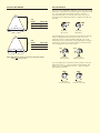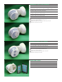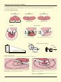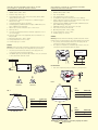
1
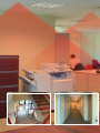
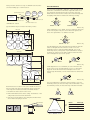
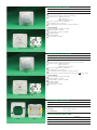
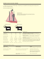
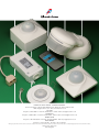
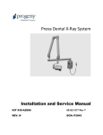
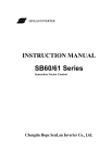
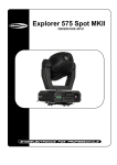
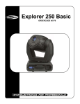
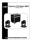
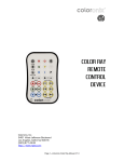
Occupancy sensors
& PIRs
Various locations where motion sensors can be used are general office, stairwell, corridors outdoor applications.
Master & slave
flush ceiling
motion sensors
Crabtree’s range of occupancy sensors are designed
to offer a quick and easy plug n play installation
whilst offering savings to lighting energy
consumption.
It is estimated that 70% of the UK’s lighting
consumption is used in commercial applications.
Studies of several rooms in different commercial
environments installed with occupancy sensors,
show that on average, 41% of lighting costs could be
saved. By using Crabtree’s plug n play solution users
can achieve these savings with a minimal investment,
in time and money.
The versatility of the Crabtree plug n play
installation makes the product ideal for coverage in
all room shapes as well as a single detection zone
having multiple sensor locations.
The master unit has power connected to a power
supply module. Plug n play is then achieved by slave
units connecting to each other via a supplied RJ11
cable in a daisy chain arrangement.
Further to the plug n play Master and Slave system
the range is further complimented by a dedicated
Ceiling and Corridor Sensor. The flush or surface
mounted sensors have the largest known detection
zone in the market, 24 metre diameter when fitted
at optimal height.
The existing Crabtree Minder IP55 PIR range offers
solutions for installations in arduous conditions.
CEILING MASTER MOTION SENSOR
l
PACK QTY
Ceiling Master Motion Sensor
1
6004
Detection circular 360º
8 metre diameter detection zone at 2.4 metre height
● Switching capacity: 1800W Incandescent
1100VA Fluorescent
1100VA Energy Saving Lamp
● Time adjustment 30 sec to 30 min
● Photocell: Lux adjustment 5 to 1000 LUX
● Sensor adjustment 1 metre diameter to 8 metre diameter
● Power box supplied with master motion sensor
● 5 slave motion sensors can be connected in line with 1 master motion sensor
● Master motion sensor comes complete with 30cm RJ12 patch cord
● Plastic shroud supplied to help mask the lens if there are any undesired areas
●
●
6004
Product standards
EN 55015:2006 + A1:2007
● EN 61547:1995 + A1:2000
● EN 61000-3-2:2006
● EN 61000-3-3:1995 + A1:2001 + A2:2005
● EN 60669-2-1:2004 + C1:2007 clause 26
● EN 60669-2-1:2004 + C1:2007
● EN 60669-1:1999 + A1:2002 + A2:2008 exc clause 19.102
101.1.1.2
101.3
●
6004 open showing adjustment dials
CEILING SLAVE MOTION SENSOR
l
PACK QTY
Ceiling Slave Motion Sensor
1
No wiring required
Detection circular 360º
● 8 metre diameter detection zone at 2.4 metre height
● Switching capacity: 1800W Incandescent
1100VA Fluorescent
1100VA Energy Saving Lamp
● Sensor adjustment 1 metre diameter to 8 metre diameter
● 5 slave motion sensors can be connected in line with 1 master motion sensor
● Slave sensor comes complete with 5 metre RJ11 patch cord
● Plastic shroud supplied to help mask the lens if there are any undesired areas
●
●
6005
Product standards
EN 55015:2006 + A1:2007
● EN 61547:1995 + A1:2000
● EN 61000-3-2:2006
● EN 61000-3-3:1995 + A1:2001 + A2:2005
● EN 60669-2-1:2004 + C1:2007 clause 26
● EN 60669-2-1:2004 + C1:2007
● EN 60669-1:1999 + A1:2002 + A2:2008 exc clause 19.102
101.1.1.2
101.3
●
6005 open showing adjustment dial
6005
Each power box can have not only one MASTER sensor but also
can extend flexibly up to 5 SLAVE sensors.
6004
MASTER
SENSOR
30cm RJ12 Patch Cord
6005
SLAVE
SENSOR
ADJUSTMENTS
l
The sensor has an adjustable “TIME ON” control from 30 seconds
minimum to a maximum of 30 minutes. Light will remain on for
the setting time interval after the last movement is detected.
While there is movement from a heat source in the detecting area
the lighting will remain on and the time will keep resetting.
6005
SLAVE
SENSOR
6004
POWER BOX
1
30cm RJ11 Patch Cord
0.2m 1x2 RJ12 Patch Cord
3
5
10
20
30S
5m 1x2 RJ11 Patch Cord
1
3
30S
5
10
20
NOTE: Master x1 – Slave x5
30
PULSE
PULSE
Typical maximum layout of master followed by 5 slaves
Master only
If time adjustment is set to PULSE, the sensor will enter short pulse
mode. In short pulse mode, the sensor will send a signal to the
device. The signal will be 1 sec ON and 9 sec OFF.
18m total
5m
4m
Slave 1
6005
Slave 2
6005
1
5m
Master
6004
4m
5m
Slave 3
6005
Slave 4
6005
5m
20
30
Master only
4m
4m
5m
10
The LUX adjustment controls the light level at which the unit will
switch on the light when movement is sensed. If set to the
maximum position, it will switch during daylight. If set to the
minimum position, it will operate only in total darkness. Ideally it
should be set at dusk or in the light conditions under which the
sensor and lights are expected to operate.
18m total
4m
5
PULSE
4m
Slave 5
6005
3
30S
13m total
4m
30
Slave 1
6005
Slave 2
6005
TEST
TEST
5m
Master
6004
18m total
Master only
5m
Slave 3
6005
Slave 5
6005
4m
Slave 4
6005
If LUX adjustment is set to maximum, the sensor will enter TEST
mode. In TEST mode, the light will turn on for 3 sec when PIR is
triggered. Check the detection area and adjust sensor to the
desired angle. Afterwards, it can be switched back to desired time
setting.
TEST
4m
5m
Master only
4m
The sensor adjustment controls the detection range. If set to the
maximum position, the detection range is about 4m radius. If set to
the minimum position, the detection range is about 0.5m radius.
13m total
Determine the best location for the sensor. Install the sensor at
least 1m away from fluorescent and HVAC ducts, and at least
1.3m away from incandescent fixtures and HVAC diffusers.
S
S
1. Determine the best location for the sensor.
2. Drill a 63mm diameter hole in the ceiling. The thickness of the
ceiling must be between 5mm and 25mm.
3. Insert the power module into the ceiling first and then fix the
sensor with metal spring as shown.
360º
Power Module
2.4m
High
Ceiling 5-25mm
63mm
Ø 8m
NL
HEIGHT
RADIUS (M)
2.3
3.5
2.4
4
3.0
5.5
CEILING MOTION SENSOR
l
PACK QTY
Ceiling Motion Sensor
1
6001
360º Detection range, flush mounting
24 metre diameter detection zone at 3 metre height
● Switching capacity: 1000W Incandescent
500VA Fluorescent
500VA Energy Saving Lamp
● Photocell: Lux adjustment 2 to 1000 LUX
● Time adjustment 10 sec to 20 min
● Sensor adjustment 4 metre diameter to 24 metre diameter
●
●
6001
Product standards
EN 60669-1:1999 + A1:2002 + A2:2008
● EN 60669-2:2004 + A1:2009
● EN 55015:2006 + A1:2007 + A2:2009
● EN 61000-3-2:2006
● EN 61000-3-3:2008
● EN 61547:1995 + A1:2000
●
Rear view of product 6001
CORRIDOR MOTION SENSOR
l
PACK QTY
Corridor Motion Sensor
1
6002
360º Detection range, flush mounting
24 metre in length 6 metre width detection range at 3 metre height
● Switching capacity: 1000W Incandescent
500VA Fluorescent
500VA Energy Saving Lamp
● Photocell: Lux adjustment 2 to 1000 LUX
● Time adjustment 10 sec to 20 min
● Sensor adjustment 4 metre diameter to 24 metre diameter
● Detection range is achieved by aligning the double arrow
along corridor
●
t
6002
t
●
Product standards
EN 60669-1:1999 + A1:2002 + A2:2008
● EN 60669-2:2004 + A1:2009
● EN 55015:2006 + A1:2007 + A2:2009
● EN 61000-3-2:2006
● EN 61000-3-3:2008
● EN 61547:1995 + A1:2000
●
Rear view of product 6002
FLUSH MOUNT BACK BOX
l
PACK QTY
1 Gang 47mm deep dry lining back box
Tile Thickness
6.35 to 15mm
Dimensions
83mm x 83mm x 48mm
Cut out dimension
73mm x 73mm
SURFACE MOUNT BACK BOX
6003
SB632
10
SB632
l
PACK QTY
1 Gang 39mm deep
Dimensions
1
90mm x 90mm x 39mm
6003
DETECTION RANGE
l
6001
Ø 24m
l
The sensor has an adjustable “TIME ON” control from 10 seconds
minimum to a maximum of 20 minutes (approx). Light will remain
on for the setting time interval after the last movement is
detected. While there is movement from a heat source in the
detecting area the lighting will remain on and the time will keep
resetting.
360º
3m
High
ADJUSTMENTS
HEIGHT
RADIUS (M)
2.3
10
2.5
11
3.0
12
TIME
TIME
+
+
Minimum
10 seconds
360º
6002
3m
High
12m
3m
HEIGHT
RADIUS (M)
2.5
11
3.0
12
Maximum
20 minutes
The LUX adjustment controls the light level at which the unit will
switch on the light when movement is sensed. If set to the
maximum position, it will switch during daylight. If set to the
minimum position, it will operate only in total darkness. Ideally it
should be set at dusk or in the light conditions under which the
sensor and lights are expected to operate.
LUX
LUX
12m
3m
t
t
NOTE: 6002 detection range is achieved by aligning the double
arrow
along corridor.
Minimum
dark operation
Maximum
daylight operation
The sensor adjustment controls the detection range. If set to the
Maximum position “+”, detection range is approximately 12m
radius, if set to the Minimum position “–”, detection range is
approximately 2m radius.
SENS
SENS
+
Minimum
2m detected range
+
Maximum
12m detected range
MINDER 90°, 220° & 280° SENSORS
IP55
l
PACK QTY
Passive infrared motion detector which switches consumers through a
timing element when sources of heat move within its range.
Minder 90 Deg PIR sensor, no remote control,
surveillance range 12m frontal, 6m lateral
1
6853
Minder 220 Deg PIR sensor, c /w remote control,
surveillance range 16m frontal & lateral
1
6845
Minder 280 Deg PIR sensor, c /w remote control,
surveillance range 16m frontal & lateral
1
6846
Dimensions
●
●
6845
●
●
●
102mm x 102mm x 182mm
Minder 90° and 220° can be swivelled vertically +90° -40°
Sensor head can be swivelled horizontally +/- 65°
Can be wall or ceiling mounted
Minder 90° and 220° offer rear-field “anti-creep” protection
Maximum Switching current 16AX
6846
MINDER SECURITY 220° SENSOR
IP55
l
PACK QTY
Minder Security 220 Deg PIR sensor, c /w remote
control,surveillance range 16m frontal & lateral
Dimensions
●
●
●
●
●
1
6849
102mm x 102mm x 182mm
Minder 220° can be swivelled vertically +90° -40°
Sensor head can be swivelled horizontally +/- 65°
Can be wall or ceiling mounted
Minder 220° offers rear-field “anti-creep” protection
Maximum Switching current 16AX
6849
ANCILLIARY ITEMS
l
PACK QTY
6887
Corner mounting bracket
6841
6842
1
6887
Manual remote control
1
6841
Service Manual remote control
1
6842
MINDER PASSIVE INFRA RED SENSORS
l
The Minder is a multi-adjustable, passive infrared movement detector. People and animals radiate heat, which
is invisible to the human eye (infrared range). Consequently, the recorded infrared energy pattern changes when
they enter the detection zone
DETECTION RANGE DIAGRAMS
90º
Rearfield detection
6m
6m
220º
Rearfield detection
280º
Rearfield detection
Range up to 16m
Range up to 16m
Range up to 12m
Minder 280
Insatallation sites
Be aware of trees and bushes
Do not install outside lights in detection zone
+-30˚
2.5m
Settings/Restrictions of detection
+90˚
LED
1m
-40˚
16m 220˚ & 280˚
12m 90˚
+-30˚
The various detection levels
To fully cover the surveillance zone, the Fresnel lens splits the zone into several overlapping levels.
Level 2
Level 1
Level 4
Level 3
Levels 1 and 2 cover remote surveillance and ensure seamless detection
when the surveillance zone is entered from the outside.
Level 3 covers close range detection to prevent undetected entry of the
surveillance zone close to the wall.
Level 4 covers the rearfield detection, which is activated when the front
door is opened from the inside.
CEILING FLUSH-MOUNT MASTER & SLAVE
OCCUPANCY SENSOR 6004 & 6005
l
6001/6002 CEILING & CORRIDOR MOUNT
INDOOR MOTION SENSOR
SPECIFICATION:
SPECIFICATION:
1.
2.
3.
1.
2.
3.
4.
5.
4.
5.
6.
7.
8.
9.
10.
11.
12.
13.
POWER: 220V to 240V ~ 50Hz.
Detection range: refer to fig. 1.
Time adjustment: 30 sec, 1min, 3min, 5min, 10min, 20min, 30min
(apply to Master sensor only)
Lux adjustment: ‘Light level’ sensing from 5 to 1000 Lux. (apply to
Master Sensor only)
Sensitivity adjustment: 0.5m to 4m radius.
Switching capacity: 1800W incandescent light / 1100VA fluorescent
light / 1100VA Energy saving lamp
Master sensor can be connected to up to 5 slave sensors.
Warm up: 60 sec.
Test mode: Lux adjustment switch to maximum. Light turns on for 3
sec in each trigger.
Short time pulse mode: Time adjustment switch to minimum. 1 sec
ON, 9 sec OFF.
Operating temperature: -10ºC to +40ºC.
Storage temperature: -25ºC to +70ºC.
Terminal capacity: 2 x 1.5mm2.
WIRING:
Warning: Products should be installed by a qualified electrician. Ensure
that the sensor is fixed securely to the ceiling without any movement.
1. The phase (L) and neutral (N) conductors of the supply cable are
connected according to terminal assignment.
2. The OUTPUT phase (L’) and neutral (N) conductors are to be connected
to the load terminals marked L’ and N.
POWER: 220V to 240V ~ 50Hz.
Fuse: T6.3A, 250VAC.
Time adjustment from 10sec to 20min.
Lux adjustment: ‘Light level’ sensing from 2 Lux to 1000 Lux.
Range of detection from 2m to 12m radius. Detection range can be
adjusted using the supplied shroud stickers
6. Switching capacity: 1000W incandescent light / 500VA fluorescent
light / 500VA Energy saving lamp.
7. 6001/6002 detection range: please refer to the fig.2.
8. Auto mode / Test mode / Timer mode.
9. Operating temperature: -10ºC to +40ºC.
10. Storage temperature: -25ºC to +70ºC.
11. Terminal capacity: 2 x 1.5mm2.
WIRING:
Warning: Products should be installed by a qualified electrician. Ensure
that the sensor is screwed securely to the ceiling without any movement.
1. The phase (L) and neutral (N) conductors of the supply cable are
connected according to terminal assignment.
2. The output (or load) phase (L’) and neutral (N) connectors are to be
connected to the load terminals marked L’ and N.
6001 / 6002
N N
N
N
L
N
L
L L’
L’
N
N
N
L
L’
N
L
L’
L
INSTALLATION:
1.
S
Fuse can be replaced by using a screwdriver to pull up the fuse.
S
N
N
L
L’
FIG. 2
360º
Minimum
Maximum
6001
FIG. 1
3m
High
360º
Ø 24m
2.4m
High
HEIGHT
RADIUS (M)
2.3
3.5
2.4
4
3.0
5.5
HEIGHT
RADIUS (M)
2.3
10
2.5
11
3.0
12
360º
Ø 8m
6002
3m
High
12m
3m
HEIGHT
RADIUS (M)
2.5
11
3.0
12
12m
3m
t
t
NOTE: 6002 detection range is achieved by aligning the double
arrow
along corridor.
l
MINDER PASSIVE INFRA RED SENSORS
l
The Minder is a multi-adjustable, passive infrared movement detector. People and animals radiate heat, which
is invisible to the human eye (infrared range). Consequently, the recorded infrared energy pattern changes when
they enter the detection zone
DETECTION RANGE DIAGRAMS
Rearfield detection
Additional protection for windows and doors up to the wall of the house,
even in case of installation directly above doors and windows, is provided
by the integrated rearfield detection.
Standard Connection
L
N
With Break Switch
LS 16A
L
N
N
LS 16A
N
L
L
TECHNICAL DATA
l
Horizontal range
of detection
90˚
220˚
280˚
Max. frontal range
12m
16m
16m
Max. bilateral range
6m
16m
10m
Water protection
IP55
IP55
IP55
Switch off delay
1-3-5min
10 sec-30min
10 sec-30min
Dusk sensor, in Lux
3/15/Lux
0,5-300/Lux
0,5-300/Lux
Switching Capacity
3680 W/VA
3680 W/VA
3680 W/VA
Max switching Current
16AX
16AX
16AX
Operating Temperature
-25˚C - +55˚C
-25˚C - +55˚C
-25˚C - +55˚C
INSTALLATION
l
The Minder functions optimally when installed lateral to walking direction.
When selecting the installation site, ensure that:
● The minder is not covered by rigid or moveable objects (e.g. roofing elements,
branches of tree, etc.).
● When unit is installed above, or lateral to luminaires, a minimum distance is
always allowed between the unit and the luminaire, in order to prevent
maloperation.
● when the unit is installed below luminaires, it is not heated up as a result of
radiant heat from the luminaire.
When mounted at a height of 2.5m, the detection range is as above mentioned,
though deviations in the mounting height cause changes in the detection range.
In the case of special conditions at the site (e.g. rows of trees, small plot of land,
proximity to road, etc.) the enclosed masking strip can be used to restrict the
detection range by sticking it on the Minder lens.
MINDER FAULT FINDING ANALYSIS
l
NATURE OF FAULT
REASON FOR FAULT
REMEDY
Minder does not operate
Lens covered or dirty
Check power supply, uncover and/or clean lens
Inadvertent operation of Minder
Hot air or smoke e.g. out of kitchens activate Minder
Install Minder at a different location
Lamp is permanently on
Permanent movement in the monitored area
Make sure that no heat source is in the
detection zone and wait until adjusted time
lapse has run down.. For control purposes,
please cover the lens completely.
Minder is bridged to manual operation by
additional switch
Switch to automatic operation
ELECTRIUM SALES LIMITED A SIEMENS COMPANY
Commercial Centre, Lakeside Plaza, Walkmill Lane, Bridgtown, Cannock WS11 0XE.
eMail: [email protected] Web: www.electrium.co.uk
UK SALES
Telephone: 01543 455010 Facsimile: 01543 455011 eMail: [email protected]
TECHNICAL
Telephone: 01543 438310 Facsimile: 01543 438311 eMail: [email protected]
EXPORT SALES
Telephone: +44 1543 455049 Facsimile: +44 1543 455048 eMail: [email protected]
DUBAI OFFICE
Telephone: +971 4 3660053 Facsimile: +971 4 3660676
Although every effort has been made to ensure accuracy in the compilation of the technical detail within this publication, specifications and performance data are constantly changing. Latest details can be obtained from Crabtree.
Publication No. A2073 10/12
Printed in England.