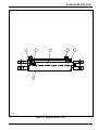
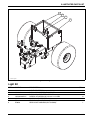
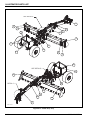
1
Model 1432/1632/1632RS Grader Service and Parts Manual LANDOLL CORPORATION 1900 North Street Marysville, Kansas 66508 (785) 562-5381 800-428-5655 ~ WWW.LANDOLL.COM F-740-1213 12/2013 1-2 F-740-1213 Edition Table of Contents 1 Introduction Understanding Safety Statements . . . . . . . . . . . . . . . . . . . . . . . . . . . . . . . . . . . . . . . . . . . . . . . . 1-2 2 Standard Specifications Specifications . . . . . . . . . . . . . . . . . . . . . . . . . . . . . . . . . . . . . . . . . . . . . . . . . . . . . . . . . . . . . . . . . 2-2 3 Safety Information Introduction . . . . . . . . . . . . . . . . . . . . . . . . . . . . . . . . . . . . . . . . . . . . . . . . . . . . . . . . . . . . . . . . . . 3-1 Owner Assistance . . . . . . . . . . . . . . . . . . . . . . . . . . . . . . . . . . . . . . . . . . . . . . . . . . . . . . . . . . . . . 3-1 Warranty Registration . . . . . . . . . . . . . . . . . . . . . . . . . . . . . . . . . . . . . . . . . . . . . . . . . . . . . . . . . . 3-1 Understanding Safety Statements . . . . . . . . . . . . . . . . . . . . . . . . . . . . . . . . . . . . . . . . . . . . . . . . 3-3 Safety Decals . . . . . . . . . . . . . . . . . . . . . . . . . . . . . . . . . . . . . . . . . . . . . . . . . . . . . . . . . . . . . . . . . Pinching or Crushing Danger . . . . . . . . . . . . . . . . . . . . . . . . . . . . . . . . . . . . . . . . . . . . . . . . Moving Parts . . . . . . . . . . . . . . . . . . . . . . . . . . . . . . . . . . . . . . . . . . . . . . . . . . . . . . . . . . . . . Danger . . . . . . . . . . . . . . . . . . . . . . . . . . . . . . . . . . . . . . . . . . . . . . . . . . . . . . . . . . . . . . . . . . Caution . . . . . . . . . . . . . . . . . . . . . . . . . . . . . . . . . . . . . . . . . . . . . . . . . . . . . . . . . . . . . . . . . Danger, High Pressure . . . . . . . . . . . . . . . . . . . . . . . . . . . . . . . . . . . . . . . . . . . . . . . . . . . . . Horsepower Limits . . . . . . . . . . . . . . . . . . . . . . . . . . . . . . . . . . . . . . . . . . . . . . . . . . . . . . . . . Lubrication . . . . . . . . . . . . . . . . . . . . . . . . . . . . . . . . . . . . . . . . . . . . . . . . . . . . . . . . . . . . . . . Proper Notification . . . . . . . . . . . . . . . . . . . . . . . . . . . . . . . . . . . . . . . . . . . . . . . . . . . . . . . . . 3-7 3-7 3-7 3-7 3-7 3-7 3-7 3-7 3-7 Storage Recommendations . . . . . . . . . . . . . . . . . . . . . . . . . . . . . . . . . . . . . . . . . . . . . . . . . . . . . . 3-7 4 Assembly and Lubrication Assembly and Lubrication Check List . . . . . . . . . . . . . . . . . . . . . . . . . . . . . . . . . . . . . . . . . . . . . 4-1 Lubrication Maintenance . . . . . . . . . . . . . . . . . . . . . . . . . . . . . . . . . . . . . . . . . . . . . . . . . . . . . . . . 4-1 Storage . . . . . . . . . . . . . . . . . . . . . . . . . . . . . . . . . . . . . . . . . . . . . . . . . . . . . . . . . . . . . . . . . . . . . . 4-1 5 Hookup and Operation Tie Strap Designations . . . . . . . . . . . . . . . . . . . . . . . . . . . . . . . . . . . . . . . . . . . . . . . . . . . . . . . . . 5-1 Hookup to the Remote . . . . . . . . . . . . . . . . . . . . . . . . . . . . . . . . . . . . . . . . . . . . . . . . . . . . . . . . . . 5-2 Learning to Operate the Grader . . . . . . . . . . . . . . . . . . . . . . . . . . . . . . . . . . . . . . . . . . . . . . . . . . 5-2 6 Illustrated Parts List General Assembly . . . . . . . . . . . . . . . . . . . . . . . . . . . . . . . . . . . . . . . . . . . . . . . . . . . . . . . . . . . . . 6-1 Grader Assembly . . . . . . . . . . . . . . . . . . . . . . . . . . . . . . . . . . . . . . . . . . . . . . . . . . . . . . . . . . . . . . 6-6 F-740-1213 Edition i Grader Assembly Standard Models . . . . . . . . . . . . . . . . . . . . . . . . . . . . . . . . . . . . . . . . . . . . . . 6-10 Item . . . . . . . . . . . . . . . . . . . . . . . . . . . . . . . . . . . . . . . . . . . . . . . . . . . . . . . . . . . . . . . . . . . . . . . . 6-10 Part No. . . . . . . . . . . . . . . . . . . . . . . . . . . . . . . . . . . . . . . . . . . . . . . . . . . . . . . . . . . . . . . . . . . . . . 6-10 Description . . . . . . . . . . . . . . . . . . . . . . . . . . . . . . . . . . . . . . . . . . . . . . . . . . . . . . . . . . . . . . . . . . 6-10 . . . . . . . . . . . . . . . . . . . . . . . . . . . . . . . . . . . . . . . . . . . . . . . . . . . . . . . . . . . . . . . . . . . . . . . . . . . . 6-10 Hub And Axle Assembly . . . . . . . . . . . . . . . . . . . . . . . . . . . . . . . . . . . . . . . . . . . . . . . . . . . . . . . 6-12 7,000 Lb. Sidewind Jack Assembly . . . . . . . . . . . . . . . . . . . . . . . . . . . . . . . . . . . . . . . . . . . . . . 6-14 Hydraulic Assembly . . . . . . . . . . . . . . . . . . . . . . . . . . . . . . . . . . . . . . . . . . . . . . . . . . . . . . . . . . . 6-18 Hydraulic Cylinder, 4 X 12 . . . . . . . . . . . . . . . . . . . . . . . . . . . . . . . . . . . . . . . . . . . . . . . . . . . . . . 6-20 Hydraulic Cylinder, 4 X 16 . . . . . . . . . . . . . . . . . . . . . . . . . . . . . . . . . . . . . . . . . . . . . . . . . . . . . . 6-22 Hydraulic Cylinder, 5 X 24 . . . . . . . . . . . . . . . . . . . . . . . . . . . . . . . . . . . . . . . . . . . . . . . . . . . . . . 6-24 Light Kit . . . . . . . . . . . . . . . . . . . . . . . . . . . . . . . . . . . . . . . . . . . . . . . . . . . . . . . . . . . . . . . . . . . . . 6-25 Decal Kit . . . . . . . . . . . . . . . . . . . . . . . . . . . . . . . . . . . . . . . . . . . . . . . . . . . . . . . . . . . . . . . . . . . . 6-30 Gauge Wheel Kit (Option) . . . . . . . . . . . . . . . . . . . . . . . . . . . . . . . . . . . . . . . . . . . . . . . . . . . . . . 6-32 Grader Snow/Dirt Kit (Option) . . . . . . . . . . . . . . . . . . . . . . . . . . . . . . . . . . . . . . . . . . . . . . . . . . . 6-34 7 ii Numerical Index F-740-1213 Edition Chapter 1 Introduction The Landoll/Icon Model 1632RS Grader is a quality product designed to give years of trouble free performance. By following each section of this manual, your system will perform as designed for you and your operation CHAPTER 1 gives basic instructions on the use of this manual. CHAPTER 2 gives product specifications. These specifications supply lengths and measures for your equipment. A Standard Bolt Torque Table is provided to give guidelines for bolt torques to be used when servicing this product. CHAPTER 3 contains assembly instructions for your Model 1632RS Grader. When these procedures are correctly followed, your equipment should provide you years of trouble-free operation and service. CHAPTER 4 instructs how to operate your equipment before using it, and describes adjustments needed. It also gives practical advice for the care and maintenance of your Landoll equipment. Drawings in this section locate adjustment points on the equipment. NOTE: IF THE EQUIPMENT IS IMPROPERLY ASSEMBLED OR MAINTAINED, THE WARRANTY IS VOID. IF YOU HAVE ANY QUESTIONS CONTACT: LANDOLL CORPORATION 1900 NORTH STREET MARYSVILLE, KANSAS 66508 or phone: (785) 562-5381 or (800) 428-5655 or FAX: (888) 527-3909 CHAPTER 5 is a troubleshooting guide to aid in diagnosing and solving problems with the equipment. PARTS LIST is a separate manual showing the various assemblies, subassemblies, and systems. Refer to that manual when ordering Landoll replacement parts. Order parts from your Landoll dealer. WARRANTY The Warranty Registration form is included with the product documents. Fill it out and mail it within 15 days of purchase. NOTE: IMPROPER ASSEMBLY, MODIFICATION, OR MAINTENANCE OF YOUR LANDOLL MACHINE CAN VOID YOUR WARRANTY. COMMENTS Address comments or questions regarding this publication to: LANDOLL CORPORATION 1900 NORTH STREET MARYSVILLE, KANSAS 66508 ATTENTION: PUBLICATIONS -DEPT. 55 1-1 INTRODUCTION Understanding Safety Statements You will find various types of safety information on the following pages and on the machine signs (decals) attached to the vehicle. This section explains their meaning. The Safety Alert Symbol means ATTENTION! YOUR SAFETY IS INVOLVED! DANGER Danger means a life-threatening situation exists. Death can occur if safety measures or instructions on this label are not properly followed. WARNING Warning means serious injury or death can occur if safety measures or instructions on this label are not properly followed. CAUTION Caution means serious equipment or other property damage can occur if instructions on this label are not properly followed. NOTE Means that failure to follow these instructions could cause damage to the equipment or cause it to operate improperly. NOTE Make sure you read and understand the information contained in this manual and on the machine signs (decals) before you attempt to operate or maintain this vehicle. The safety statements contained in this manual relate to the operation of the Model 1632RS Grader. 1-2 F-740-1213 Edition Chapter 2 Standard Specifications 1432/1632 GRADER MODEL BLADE WIDTH TRANSPORT WIDTH EST. WEIGHT (LBS.) 1432 14’0” 8’-4” 5,100 1632 16’-0” 8’-4” 5,300 1632RS 16’-0” 8’-4” 5,660 TIRE INFLATION TIRE SIZE 19L x 16.1 12 ply 20.5 x 8.0-10 TIRE MANUFACTURER Firestone or equivalent PLY/LOAD RATING Farm Implement Tread 6600 lbs. @ 30 mph Load Range D/ 1,320 lb. INFLATION PRESSURE (PSI) (MAX.) 36 psi 70 psi SPECIFIC BOLT TORQUES Center Frame Spindle Nuts: Inner Outer Center Frame Wheel Nuts: Wing Frame Wheel Nuts: Disc Gang Shafts 9/16-18 Lug Bolts and Nuts (Heavy Duty Disc) 5/8-18 Lug Bolts and Nuts (Heavy Duty Disc) 50 Ft./Lbs. 300 Ft./Lbs. 450 - 500 Ft./Lbs. 85 - 100 Ft./Lbs. 1,200 Ft./Lbs. 80 - 90 ft. lbs 85 - 100 ft. lbs 2-1 STANDARD SPECIFICATIONS Specifications • Model 1432 • Standard 6” x 7’ cutting edges on 16’ x 32” blade. • Standard folding box ends, to convert to box scraper. • Four way operation to raise/lower, blade tilt side to side, and blade rotation. And rear steer. • Pintle style hitch w/bolt on hammer strap. Rated at 68,800 lbs. • Maximum tractor horsepower is 300 hp. • Shipping Weight 1432 - 5100 lbs. • • • Model 1632.1632RS • Standard 6” x 8’ cutting edges on 16’ x 32” blade. • Standard folding box ends, to convert to box scraper. • Four way operation to raise/lower, blade tilt side to side, and blade rotation. And rear steer. • Pintle style hitch w/bolt on hammer strap. Rated at 68,800 lbs. • Maximum tractor horsepower is 300 hp. • Shipping Weight 1632 - 5300 lbs. • Overall length is 23’. • Overall width with hydraulics attached is 9’-6”. • Transport width with hydraulics unpinned, and in transport position is 8’-4”. • Blade swing left/right is 50°, tilt side to side is 15°, blade clearance at full raised position is 18". And rear steer adds 5’ extension of blade on either side. • Tires are 19 x 16.1, on 8 bolt rims and 8000 lb. spindles (35 psi max. inflation) • Weight box should be filled prior to use. It holds app. 1/2 yd. of concrete (1500#) • Hydraulic cushion valve for blade breakaway, upon solid impact. (set at 2500psi) • Standard light package. • Cylinders are welded industrial — 5 x 24 blade swing — 4 x 12 tilt 1632RS - 5,660 lbs. • Overall length is 23’. • Overall width with hydraulics attached is 9’-6”. • Transport width with hydraulics unpinned, and in transport position is 8’-4”. • Blade swing left/right is 50°, tilt side to side is 15°, blade clearance at full raised position is 18". And rear steer adds 5’ extension of blade on either side. • Tires are 19 x 16.1, on 8 bolt rims and 8000 lb. spindles (35 psi max. inflation) • Weight box should be filled prior to use. It holds app. 1/2 yd. of concrete (1500#) • Hydraulic cushion valve for blade breakaway, upon solid impact. (set at 2500psi) • Standard light package. • Cylinders are welded industrial — 5 x 24 blade swing — 4 x 16 raise/lower — 4 x 12 tilt — 4 x 16 rear steer — 4 x 16 raise/lower • 9 total grease locations. • Requires 4 remotes on the tractor (8 hoses). • Standard angle gauge. • 3000 psi hydraulic hoses. — 4 x 16 rear steer • 9 total grease locations. • Requires 4 remotes on the tractor (8 hoses). • Standard angle gauge. • 3000 psi hydraulic hoses. • 2-2 F-740-1213 Edition STANDARD SPECIFICATIONS LANDOLL CORPORATION GENERAL TORQUE SPECIFICATIONS (REV. 4/97) THIS CHART PROVIDES TIGHTENING TORQUES FOR GENERAL PURPOSE APPLICATIONS WHEN SPECIAL TORQUES ARE NOT SPECIFIED ON PROCESS OR DRAWING. ASSEMBLY TORQUES APPLY TO PLATED NUTS AND CAPSCREWS ASSEMBLED WITHOUT SUPPLEMENTAL LUBRICATION (AS RECEIVED CONDITION). THEY DO NOT APPLY IF SPECIAL GRAPHITE MOLY-DISULFIDE OR OTHER EXTREME PRESSURE LUBRICANTS ARE USED. WHEN FASTENERS ARE DRY (SOLVENT CLEANED), ADD 33% TO AS RECEIVED CONDITION TORQUE. BOLT HEAD IDENTIFICATION MARKS INDICATE GRADE AND MAY VARY FROM MANUFACTURER TO MANUFACTURER. THICK NUTS MUST BE USED ON GRADE 8 CAPSCREWS. USE VALUE IN [ ] IF USING PREVAILING TORQUE NUTS. TORQUE IS SPECIFIED IN FOOT POUNDS UNC Size 1/4-20 5/16-18 3/8-16 7/16-14 1/2-13 9/16-12 5/8-11 3/4-10 7/8-9 1-8 1-1/8-7 1-1/4-7 1-3/8-6 1-1/2-6 1-3/4-5 SAE Grade 2 4 8 15 24 35 55 75 130 125 190 270 380 490 650 736 [5] [10] [19] [30] [43] [62] [94] [162] [156] [237] [337] [475] [612] [812] [920] SAE Grade 5 6 13 23 35 55 80 110 200 320 408 600 840 110 1460 1651 [7] [16] [29] [43] [62] [100] [137] [250] [400] [506] [750] [1050] [1375] [1825] [2063] SAE Grade 8 9 18 35 55 80 110 170 280 460 680 960 1426 1780 2360 2678 [11] [22] [43] [62] [100] [137] [212] [350] [575] [850] [1200] [1782] [2225] [2950] [3347] UNF Size 1/4-28 5/16-24 3/8-24 7/16-20 1/2-20 9/16-18 5/8-18 3/4-16 7/8-14 1-14 1-1/8-12 1-1/4-12 1-3/8-12 1-1/2-12 1-3/4-12 SAE Grade 2 5 9 17 27 40 60 85 150 140 210 300 420 560 730 920 [6] [11] [21] [34] [50] [75] [106] [188] [175] [263] [375] [525] [700] [912] [1150] SAE Grade 5 7 14 25 40 65 90 130 220 360 540 660 920 1260 1640 2063 [9] [17] [31] [50] [81] [112] [162] [275] [450] [675] [825] [1150] [1575] [2050] [2579] SAE Grade 8 10 20 35 60 90 130 180 320 500 760 1080 1500 2010 2660 3347 [12] [25] [44] [75] [112] [162] [225] [400] [625] [950] [1350] [1875] [2512] [3325] [4183] METRIC COARSE THREAD METRIC CLASS 10.9 FASTENERS AND CLASS 10.0 NUTS AND THROUGH HARDENED FLAT WASHERS, PHOSPHATE COATED, ROCKWELL “C” 38-45. USE VALUE IN [ ] IF USING PREVAILING TORQUE NUTS. Standard Torque Nominal Thread Diameter mm 6 7 8 10 12 14 16 18 NewtonMeters 10 16 23 46 80 125 200 275 [14] [22] [32] [60] [101] [155] [240] [330] FootPounds Nominal Thread Diameter mm 7 [10] 20 385 12 [16] 24 670 17 [24] 27 980 34 [47] 30 1330 60 [75] 33 1790 90 [115] 36 2325 150 [180] 39 3010 205 [245] Table 2-1: General Torque Specifications Standard Torque NewtonMeters [450] [775] [1105] [1470] [1950] [2515] [3210] FootPounds 290 500 730 990 1340 1730 2240 [335] [625] [825] [1090] [1450] [1870] [2380] 2-3 STANDARD SPECIFICATIONS LANDOLL CORPORATION HYDRAULIC FITTING TORQUE SPECIFICATIONS 37o JIC, ORS, & ORB (REV. 10/97) THIS CHART PROVIDES TIGHTENING TORQUES FOR HYDRAULIC FITTING APPLICATIONS WHEN SPECIAL TORQUES ARE NOT SPECIFIED ON PROCESS OR DRAWING. ASSEMBLY TORQUES APPLY TO PLATED CARBON STEEL AND STAINLESS STEEL FITTINGS ASSEMBLED WITHOUT SUPPLEMENTAL LUBRICATION (AS RECEIVED CONDITION). THEY DO NOT APPLY IF SPECIAL GRAPHITE MOLY-DISULFIDE OR OTHER EXTREME PRESSURE LUBRICANTS ARE USED. BRASS FITTINGS AND ADAPTERS - 65% OF THE TORQUE VALUE FOR STEEL. STAINLESS STEEL, ALUMINUM AND MONEL - THREADS ARE TO BE LUBRICATED. TORQUE IS SPECIFIED IN FOOT POUNDS PARKER BRAND FITTINGS Dash Size -4 -5 -6 -8 -10 -12 -16 -20 -24 -32 37 Degree JIC 11-13 14-16 20-22 43-47 55-65 80-90 115-125 160-180 185-215 250-290 O-Ring (ORS) 15-17 — 34-36 58-62 100-110 134-146 202-218 248-272 303-327 — O-Ring Boss (ORB) 13-15 21-23 25-29 40-44 57.5-62.5 75-85 109-121 213-237 238-262 310-340 GATES BRAND FITTINGS Dash Size -4 -5 -6 -8 -10 -12 -14 -16 -20 -24 -32 37 Degree JIC 10-11 13-15 17-19 34-38 50-56 70-78 — 94-104 124-138 156-173 219-243 O-Ring (ORS) 10-12 — 18-20 32-40 46-56 65-80 65-80 92-105 125-140 150-180 — O-Ring Boss (ORB) 14-16 — 24-26 37-44 50-60 75-83 — 111-125 133-152 156-184 — AEROQUIP BRAND FITTINGS Dash Size -4 -5 -6 -8 -10 -12 -14 -16 -20 -24 -32 2-4 37 Degree JIC O-Ring (ORS) 11-12 10-12 15-16 — 18-20 18-20 38-42 32-35 57-62 46-50 79-87 65-70 — — 108-113 92-100 127-133 125-140 158-167 150-165 245-258 — Table 2-2: Hydraulic Fitting Torque Specifications O-Ring Boss (ORB) 14-16 18-20 24-26 50-60 72-80 125-135 160-180 200-220 210-280 270-360 — F-740-1213 Edition Chapter 3 Safety Information Introduction Warranty Registration This manual is compiled as a guide for owners and operators of the Pull Type Grader. Read it carefully so as to be able to follow the suggestions made. Please take time to understand the proper maintenance schedule and SAFE operation of your equipment. Be certain to register the grader, by online registration at www.landoll.com within 10 days of purchase or lease, in order to be on file at Landoll and eligible for Warranty. In the event that a new and inexperienced operator is placed in charge of running the equipment, they should read and understand, that part of the manual for proper maintenance and SAFE operation, and to be trained in regard by an experienced operator. Owner Assistance If customer service or repairs are needed, contact your Icon dealer. They have trained personnel, parts and service equipment specially designed for Icon products. Your machine’s parts should only be replaced with Icon parts. Have the Serial Number and complete Model Number available when ordering parts from your Icon dealer (See Figure 3-1.) Take time to read and understand the Warranty for this product. That Warranty is printed in the Owner’s Manual (See Figure 3-2), and a separate copy enclosed in the packet. ICON/Landoll reserves the right to make changes and/or add improvements to it’s products at any time without obligation to previously manufactured equipment. ICON/Landoll recommends a maximum horsepower of the pulling tractor for your grader to be 300 hp. Additional power may shorten the life of your grader and will alter the Warranty. Please take time to complete the following information for your personal reference, should you need to contact your Dealer with questions or parts needs. MODEL_____________________________________ SERIAL #____________________________________ DATE OF PURCHASE__________________________ DEALER NAME________________________________ We at ICON/Landoll wish to thank you for purchasing our product. We have spent considerable time and effort to research, design, test and develop this machine and are confident it will serve you in the use for which it was designed. 1-010006 Figure 3-1: ID Plate 3-1 SAFETY INFORMATION LANDOLL CORPORATION Product Warranty LANDOLL CORPORATION 1600 W. 8th St. Beloit KS 67420 (referred to as LANDOLL in this document) LANDOLL shall Warrant workmanship and materials on the ICON Farm Products for a period of 12 months from the date of original purchase, lease, or rental, from the original Dealer, and in accordance with the following terms and conditions. Should any part or component fail within the Warranty period, and under normal use conditions, LANDOLL shall supply a new part or component for replacement through the original Dealer. Cost of normal ground freight, for that part or component to the Dealer, shall be paid by LANDOLL. Repair and replacement labor cost, from the original Dealer, shall be paid by LANDOLL at a rate negotiated by LANDOLL. No further expense shall be paid by LANDOLL, including but not limited to, loss of time or income. LANDOLL shall not provide Warranty on any part or component that has failed due to abuse, misuse, alteration, improper maintenance, or normal wear. Failure occurring while being pulled by a tractor in excess of engine horsepower, as described in the owners manual and/or posted on the machine, is considered abuse and misuse and shall not receive Warranty. Warranty applies only to normal. intermittent agricultural use, and not commercial or industrial use. In regard to some components manufactured by other companies and sold by LANDOLL, including but not limited to tires, said Warranty shall be provided solely by that manufacturing company. This Warranty applies to products sold in the United States and Canada, and is made expressly in place of all other warranties, expressed or implied. Figure 3-2: Product Warranty 3-2 F-740-1213 Edition SAFETY INFORMATION Understanding Safety Statements You will find various types of safety information on the following pages and on the machine decals (signs) attached to the implement. This section explains their meaning. NOTICE Special notice - read and thoroughly understand. CAUTION Proceed with caution. Failure to heed caution may cause injury to person or damage product. WARNING Proceed with caution. Failure to heed warning will cause injury to person or damage product. DANGER Proceed with extreme caution. Failure to heed notice will cause injury or death to person and/or damage product. NOTE You should read and understand the information contained in this manual and on the machine decals before you attempt to operate or maintain this equipment. • Examine safety decals and be sure you have the correct safety decals for the machine. See Safety Sign and Locations in Safety Section for decal locations See Figures 3-3 through 3-5 Order replacement decals through your Icon dealer. • Keep these signs clean so they can be observed readily. It is important to keep these decals cleaned more frequently than the machine. Wash with soap and water or a cleaning solution as required. • Replace decals that become damaged or lost. Also, be sure that any new machine components installed during repair include decals which are assigned to them by the manufacturer. • When applying decals to the machine, be sure to clean the surface to remove any dirt or residue. Where possible, sign placement should protect the sign from abrasion, damage, or obstruction from mud, dirt, oil etc. DANGER • Keep Riders Off of Machinery • Do not allow anyone to ride on tractor or machine. Riders could be struck by foreign objects or thrown from the machine. • Never allow children to operate equipment. • Keep bystanders away from machine during operation. 3-3 SAFETY INFORMATION SEE DETAIL A SEE DETAIL B SEE DETAIL C 1632rs safety decals Figure 3-3: Safety Decal Locations (1 of 3) 3-4 F-740-1213 Edition SAFETY INFORMATION 4000931 DETAIL A 4000931 1632RS DECALS 2 DETAIL B Figure 3-4: Safety Decal Locations (2 of 3) 3-5 SAFETY INFORMATION 4000625 DETAIL C 1632RS safety decals 3 Figure 3-5: Safety Decal Locations (3 of 3) 3-6 F-740-1213 Edition SAFETY INFORMATION Safety Decals Horsepower Limits See Figures 3-3 through 3-5 for decal locations. 1. Each machine is rated for it’s horsepower limits. 2. If the posted limits are exceeded, damage to the machine may occur, and the Warranty will void. NOTE Replace all missing or damaged safety signs/decals. NOTE Pinching or Crushing Danger 1. Moving parts that are operated by hydraulic pressure can cause serious injury or death. 2. Use extreme caution when working around any moving part. 300 maximum engine h.p. is only applicable if the grader is equipped with the 2nd cylinder. Lubrication 1. Lubrication information is placed near each zerk. 3. Do not allow any person to be on or near the machine while it is in motion. 2. Proper maintenance should be followed to assure the working life of the machine. Moving Parts Proper Notification 1. Be aware of all moving parts of the machine. 1. Contact the proper authorities before you dig. 2. Do not allow anyone to be near, or on the machine while operating any moving part. 2. When digging in a populated area, it is recommended that a call be made to area utilities to establish the local of any buried pipes, lines, or structures. When digging in open areas, research and know the local of any underground structures and objects. Danger 1. Read and understand the operator’s manual before using the machine. 2. Allow no person to operate the machine before reading the manual and being instructed on proper operation. 3. Striking the blades or bits against buried objects can cause damage to the machine, and is considered as abuse to the scraper. Storage Recommendations Caution 1. This machine is designed for off road use only. NOTE If the machine is being stored or not in use for a long period of time, it is recommended that a coating of heavy grease be applied to the exposed chrome cylinder rods. This will help to protect the coating from moisture and rust during this time. Danger, High Pressure 1. High pressure fluid can cause serious damage to hands and eyes. 2. Carefully relieve pressure before attempting any 3. adjustments. 4. Tighten all fittings before applying pressure. NOTE If fluid is sprayed into eyes or injected into skin, see doctor immediately! a CAUTION Be certain to remove the cylinder stops before using the grader. The stops are to be pinned in the holder, located on the rear frame. Failure to remove the stops will result in damage to the stop or cylinder. 3-7 SAFETY INFORMATION 3-8 F-740-1213 Edition Chapter 4 Assembly and Lubrication Assembly and Lubrication Check List 1. Install and pin pivot frame to tongue frame. 2. Pin rear frame to center pivot frame 3. Attach grader hitch and assure proper movement. 4. Install pivot pins, and insert all retaining clips. 5. Install lift/tilt pivot cylinders. Install all cylinder pins and retaining clips. 6. Install box ends and components. Fold and check to assure they function properly. 7. Install axle and wheel components. Visually inspect tires. 8. Route hydraulic lines and tighten. 9. Install safety lighting components, route wiring, and install plug retainer. Cycle and check lighting system with 12 volt system tester. 10. Lubricate all moving components with high temp grease. 11. Fill hydraulic systems with Mobil 424 hydraulic oil using hydraulic pump, activate all moving parts and bleed air from the system. Hold 3000 psi. hydraulic pressure against all cylinders, fittings, and hoses. 12. Check hydraulic components for leaks. Lubrication Maintenance 1. Table 4-1 specifies the number and the period of lubrication points on the 1632RS Grader. Proper maintenance of your machine will, under normal operating conditions, help to keep it operating at or near its peak performance for an extended period of time. Proper maintenance is also a condition of keeping your warranty in good status (See Figure 4-1.) 2. When lubricating the 1632RS, SAE multi-purpose EP grease, or EP grease with 3-5% molybdenum sulfide is recommended. Wipe soil from fittings before greasing. Replace any lost or broken fittings immediately. 3. Regular lubrication will extend service life, particularly in severe operating conditions. Storage 1. The service life of the 1632RS Grader will be extended by proper off-season storage practices. Prior to storing the unit, complete the following procedures: a. Completely clean the unit. b. Inspect the machine for worn or defective parts. Replace as needed. c. Repaint all areas where the original paint is worn off. 13. Recheck that all retainers are installed. 14. Assure the rear steer components function properly. 15. Clean and touch up paint the machine. 16. Attach operators manual and container. 17. Apply the safety, operations, and lube identification decals. Attach plastic envelope with warranty info, and this check list, at the front of the hose holder. 18. For ease of transporting, assure that the blade is level, and in the transport position before leaving shop. d. Grease all exposed metal surfaces of shanks, points and discs. e. Apply a light coating of oil or grease to exposed cylinder rods to prevent them from rusting. f. Lubricate each point of the machine as stated in “Lubrication Maintenance” on page 4-1. 2. Store the unit in a shed or under a tarpaulin to protect it from the weather. The ground tools and tires should rest on boards, or some other object, to keep them out of the soil. 4-1 ASSEMBLY AND LUBRICATION 4 3 5 2 1 1632 rs lubrication chart Figure 4-1: Lubrication Schedule LUBRICATION TABLE ITEM DESCRIPTION NO. OF LUBE POINTS INTERVAL 1 REAR AXLE PIVOT 1 DAILY 2 REAR AXLE SUPPORT PIN 2 DAILY 3 CENTER BLADE PIN 2 DAILY 4 HITCH PIVOT 2 DAILY 5 CENTER PIVOT 1 DAILY Table 4-1: Lubrication Table 4-2 F-607-1213 Edition ASSEMBLY AND LUBRICATION Notes 4-3 ASSEMBLY AND LUBRICATION Page Intentionally Blank 4-4 F-607-1213 Edition Chapter 5 Hookup and Operation The 1432/1632/1632 RS Grader utilizes four hydraulic valves on the tractor, allowing it to function in four different directions. The Grader has the ability to: • raise to a clearance from bit to ground of 30 inches while lowering to a negative cut. • 4000625 tilt from side to side approximately 15 degrees to accomplish slope cuts and ditching. • swing of the blade approximately 50 degrees, left or right, • control of the rear steer, 5’ in either direction. All of these functions can be done on the go, or while the grader is stopped. Tie Strap Designations Color coded tie straps and markers are attached at the tip end of the hoses to identify the four pairs of hydraulic lines to the grader. • Black tie is used on the hoses that raise and lower of the blade. • White tie is used on hoses that swing of the blade. • Yellow tie is used on hoses that tilt of the blade. • Blue tie is used on hoses that shift the rear. tie strap id NOTE Figure 5-1: Tie Strap Designations The decal is located on the tongue of the machine (See Figure 5-1.) 5-1 HOOKUP AND OPERATION Hookup to the Remote Learning to Operate the Grader Hookup of the hydraulic hoses to the remote can be done in any way to suit individual needs. The following method is suggested: Raise/Lower of the blade to #1 valve. Swing of the blade to #2, and tilt to #3, and #4 to control side shift. Be patient for the first few hours of learning to operate the grader. Time and experience will produce expert results. Any type of blade machine has the tendency to create a “washboard” effect if grading is done with too much speed. Slow down and do the job right. The second tendency of any blade machine is to side draft if the blade is cutting deep and enough power is applied. Practice centering the cut on the blade to balance the draft. Operating the Grader at a higher speed may not get the job done quicker, and may provide less than quality results. It is also recommended that the weight box be filled prior to use. This will also aid in preventing side draft, and bounce. Hook up so push of the valve is lower and pull of the valve is to raise the blade. WARNING Before angling the blade, make sure the grader is taken out of transport position. And be certain that the cylinder stops are removed before use. CAUTION When digging in a populated area, it is recommended that a call be made to area utilities to establish the local of any buried pipes, lines, or structures. When digging in open area, research and know the local of any underground structures and objects. Striking the blade and bit against surface or buried objects can cause damage to the grader and is considered as abuse to the machine. NOTICE The grader is designed to be pulled with a maximum of 300hp. Additional horsepower will shorten the life of the grader and will alter the Warranty. Responsible operation and proper maintenance will provide many hours of expert results and a durable machine. CAUTION This machine is not intended for highway use, it should be used off road only. If public roadway travel is necessary, be certain of regulations concerning width, lighting, and safety chain requirements. Operator abuse will not be a warranty item. 5-2 F-740-1213 Edition Illustrated Parts List 5 2 4 1 6 1632rs gen assembly Figure 6-1: General Assembly General Assembly ITEM PAGE NO. DESCRIPTION 1 2 3 4 5 6 7 8 6-2 - 6-6 6-11 - 6-12 6-13 - 6-14 6-15 - 6-24 6-25 - 6-25 6-26 - 6-30 6-31 - 6-32 6-33 - 6-34 GRADER ASSEMBLY HUB AND AXLE ASSEMBLY SIDEWIND JACK ASSEMBLY (NOT SHOWN) HYDRAULIC ASSEMBLIES LIGHT KIT DECAL KIT GAUGE WHEEL KIT (OPTION) (NOT SHOWN) GRADER SNOW/DIRT KIT (OPTION) (NOT SHOWN) QTY. 6-1 ILLUSTRATED PARTS LIST 57 90 89 18 39 34 26 88 90 38 85 40 53 84 86 87 14 33 30 1632rs grader assy p1 Figure 6-2: Grader Assembly (1 of 6) 6-2 F-740-1213 Edition ILLUSTRATED PARTS LIST SEE DETAIL B SEE DETAIL A 10 28 6 5 69 SEE DETAIL C 15 24 47 13 48 62 8 11 1632rs grader assy p2 Figure 6-3: Grader Assembly (2 of 6) 6-3 ILLUSTRATED PARTS LIST 29 75 80 4 37 32 4 61 19 29 80 29 27 7 56 74 23 73 77 79 12 DETAIL A 35 31 20 25 21 DETAIL B 63 65 64 66 67 50 9 10 1632RS grader assy p4 68 DETAILC Figure 6-4: Grader Assembly (3 of 6) 6-4 F-740-1213 Edition ILLUSTRATED PARTS LIST 81 76 71 66 59 78 DETAIL D 72 66 16 60 DETAIL E 58 17 70 54 SEE DETAIL E DETAIL F DETAIL D 42 DETAIL G 66 24 49 84 10 41 52 13 83 82 DETAIL G DETAIL F 1632rs grader assy p3 Figure 6-5: Grader Assembly (4 of 6) 6-5 ILLUSTRATED PARTS LIST Grader Assembly ITEM PART NO. DESCRIPTION 1 2 3 4 5 6 7 8 9 10 11 12 13 14 1-512-010010-11 155971 1-654-010047-07 1-654-010055-09 1-654-010125-20 1-654-010125-22 110-0238 118652 ICO2189 134912 140647 1408090 622-3511-010 ICO2182 ICO2205 172791 4001244 4001245 ICO0361 ICO0477 4001442 4001443 ICO0026 4001503 622-3511-007 622-3511-008 4001271 ICO0223 ICO1096 W915665-4 4000127 4000126 NUT, HEX 5/8-11 GR8 PIN, SPRING CLIP SCREW, HEX HEAD CAP 1/4-20 X 1-1/4 GR5 SCREW, HEX HEAD CAP 1/2-13 X 3 GR5 SCREW, HEX HEAD CAP 1-8 X 7-1/2 GR8 SCREW, HEX HEAD CAP 1-8 X 8-1/2 GR8 NUT, ESNA 3/4-10 NUT, HEX LOCK 1-8 TRANSPORT STRAP PIN, LYNCH 1/4 X 1-1/4 JACK, SIDEWIND 7,000# (SEE PAGE 6-14) CLEVIS PIN .375 X 4 WASHER, FLAT, 1MIL-CARB SAE 1632 MOW BOARD 1432 MOW BOARD BOLT, PLOW 5/8-11 X 2 GR8 TIRE, 19 X 16.1 RIM, 16 X 16.1 HUB AND AXLE ASSEMBLY (SEE PAGE 6-12) CYLINDER PIN, 1” (LIFT) PIN, SAFETY 3/4 X 3 GR8 PIN, BRIDGE 5/32 X 3 REAR SIDE PIPE CLAMP HITCH TONGUE CAST U CLEVIS WASHER, FLAT MIL-CARB 5/8 WASHER, FLAT MIL-CARB 3/4 BUSHING, 4OD-3.5ID SM. FLANGE SIDE PIPE CLAMP PIN, BOX END NUT, NYLOCK 1/2-13 GR5 CUTTING EDGE, 8’ GRADER BLADE CUTTING EDGE, 7’ GRADER BLADE (RIGHT) CUTTING EDGE, 7’ GRADER BLADE (LEFT) STOP, CYLINDER 16” PIVOT PIN, CYLINDER BOX END RIGHT BOX END LEFT 1/8” HAIRPIN MANUAL HOLDER REAR SIDE CLAMP REAR STEER WELDMENT REAR STEER AXLE WELDMENT 1632 DEPTH GAUGE WASHER, FLAT 1” DECAL KIT (SEE PAGE 6-30) BOLT KIT (INCLUDES ITEMS 62-77) HYDRAULIC HOSE KIT (SEE PAGE 6-18) HYDRAULIC FITTINGS KIT (SEE PAGE 6-18) LIGHT KIT (SEE PAGE 6-25) 15 16 17 18 19 20 21 22 23 24 25 26 27 28 29 30 31 32 33 34 35 36 37 38 39 40 41 42 43 44 45 46 6-6 ICO1080 ICO1078 ICO2153 ICO2154 1-557-010403 4000419 ICO0226 ICO2324 ICO2325 ICO1079 1-861-010032-25 2000602 2000616 5001147 5001148 2000620 QTY. 2 25 8 2 1 1 1 2 1 12 1 1 3 1 1 20 2 2 2 2 1 1 1 1 20 1 2 12 2 6 2 2 1 2 1 1 1 1 1 1 1 1 1 1 1 1 1 1 F-740-1213 Edition ILLUSTRATED PARTS LIST Grader Assembly ITEM PART NO. DESCRIPTION 47 48 49 50 51 52 53 54 55 56 57 58 59 60 61 62 63 64 65 66 67 68 69 70 71 72 73 74 75 76 77 78 79 80 81 82 83 84 85 86 87 88 89 90 91 4001501 861-10032-24 2-150-010008 4000096 ICO2189 SCR2160 173240 TR571 179183 1-654-010055-05 ICO2187 172892 ICO2254 ICO2255 ICO0544 141434 126561 500855 1-654-010049-12 103-0625 122962 GRA1599 63D10ER 172827 ICO0372 622-3511-007 ICO0004 ICO1117 120876 172829 1-510-010003-09 172926 1-654-010055-03 622-3511-005 172830 172839 ICO1082 ICO1077 ICO1076 ICO1051 ICO1069 ICO2183 GRA2044 ICO1075 5000 HITCH, RING CAT III WASHER, FLAT ZP/CD 1N BUSHING, 1-1/4 OD X 1 ID X 1 STEEL BUSHING TRANSPORT STRAP WASHER LOAD SHARING PIN TIRE AND WHEEL ASSEMBLY (INCL. ITEMS 16-17, 54) VALVE STEM GRADER SNOW/DIRT SKID ASSEMBLY (SEE PAGE 6-34) BOLT, HEX 1/2 X 2 GR5 1632 WEIGHT BOX NUT, HEX SLOT 2-1/2-4 10YD WEAR WASHER 10YD HITCH RETAINER CLAMP, HYD LINE SAFETY CHAIN, 21000 LB NUT, FLANGE SERRATED, 5/16-18 HYDRAULIC VALVE SCREW, HEX HEAD CAP 5/16-18 X 2-3/4 GR5 NUT, ENSA 5/8-11 SCREW, HEX HEAD CAP 5/8-11 X 4-1/2 GR8 PIN, CYLINDER 1-1/4 NUT, HEX 5/8-11 SCREW, HEX HEAD CAP 5/8-11 X 1-1/2 GR8 REAR AXLE SUPPORT PIN WASHER, FLAT MIL-CARB 5/8 HOSE STAND PIN, SPACER 3/4” SCREW, HEX HEAD CAP 3/4-10 X 6-1/2 GR8 SCREW, HEX HEAD CAP 5/8-11 X 4 GR8 NUT, FLANGE HEAD SERRATED 1/2-13 WASHER, MACHINE 2” SCREW, HEX HEAD CAP 1/2-13 X 1-1/2 GR5 WASHER, FLAT MIL-CARB 1/2 SCREW, HEX HEAD CAP 5/8-11 X 5 GR8 NUT, HEX 1-8 GR8 AGI6C DEPTH GAUGE SPACER UG16 CYLINDER PIN, W/DEPTH GAUGE MOUNT UG16 CYLINDER PIN, W/DEPTH GAUGE SLIDE UG16 CENTER PIVOT FRAME AG16C PIVOT KEEPER 1632 GRADER TONGUE UG16 PIN CENTER BLADE CYLINDER PIVOT ZERK FITTING, 1/8 QTY. 1 3 8 4 1 1 2 1 6 1 1 1 1 2 11 2 6 1 20 4 1 1 1 2 2 4 2 6 2 1 1 1 1 1 1 1 2 8 6-7 ILLUSTRATED PARTS LIST SEE DETAIL H SEE DETAIL I 1632 grader assy p2 Figure 6-6: Grader Assembly 6-8 F-740-1213 Edition ILLUSTRATED PARTS LIST 2 1 5 4 3 DETAIL H 6 7 DETAIL I 1632STD 3 Figure 6-7: Grader Assembly 6-9 ILLUSTRATED PARTS LIST Grader Assembly Standard Models Item 93 31 92 12 35 22 56 6-10 Part No. ICO0090 ICO1080 ICO2186 1408090 1-557-010403 ICO0026 1-654-010055-05 Description PIN, SPACER 9/16” STOP, CYLINDER 16” REAR AXLE SUPPORT CLEVIS PIN .375 X 4 1/8” HAIRPIN REAR SIDE PIPE CLAMP BOLT, HEX 1/2 X 2 GR5 1 1 1 1 1 1 2 F-740-1213 Edition ILLUSTRATED PARTS LIST 1 2 4 11 10 3 12 5 6 8 9 13 7 MICO0361 Figure 6-8: Hub and Axle Assembly 6-11 ILLUSTRATED PARTS LIST Hub And Axle Assembly ITEM PART NO. DESCRIPTION 1 2 3 4 5 6 7 8 9 10 11 12 13 ICO0361 ICO0360 4001062 4001057 4001061 4000582 1-861-010032-25 1-516-010001-20 110-4224 4000585 4001060 4001059 4000580 4001517 HUB AND AXLE ASSEMBLY HD16 AXLE 8,500 # HUB SEAL HUB, 7500# 8 BOLT 75-8 INNER BEARING OUTER BEARING WASHER, FLAT 1” NUT, HEX SLOT 1-14 PIN, COTTER 3/16 X 2 DUST CAP WHEEL STUD BOLT 5/8-18 INNER RACE OUTER RACE WHEEL NUT 6-12 QTY. 2 1 1 1 1 1 1 1 1 1 8 1 1 8 F-740-1213 Edition ILLUSTRATED PARTS LIST 2 3 1 4 5 7 6 m140647 Figure 6-9: 7,000 Lb. Sidewind Jack Assembly 6-13 ILLUSTRATED PARTS LIST 7,000 Lb. Sidewind Jack Assembly ITEM PART NO. DESCRIPTION 1 2 3 4 5 6 7 140647 142189 142190 142191 142192 142193 142194 142195 JACK, SIDEWIND 7000LB 9" HANDLE KIT GEAR KIT BEARING KIT BLACK HANDLE RETAINING CLIP 5/8” PIN AND CHAIN - L 5/8” FEMALE WELD-ON MOUNT 6-14 QTY. 1 1 1 1 1 1 1 F-740-1213 Edition ILLUSTRATED PARTS LIST 12 4 7 11 3 25 12 22 22 24 9 1632rs hydraulics p1 Figure 6-10: Hydraulic Assembly (1 of 3) 6-15 ILLUSTRATED PARTS LIST SEE DETAIL A SEE DETAIL B 1632rs hydraulic hoses p1 Figure 6-11: Hydraulic Assembly (2 of 3) 6-16 F-740-1213 Edition ILLUSTRATED PARTS LIST 13 23 2 14 SEE DETAIL C 23 9 5 22 DETAIL A 1 10 11 8 9 6 9 24 DETAIL B DETAIL C 1632RS hydraulic hoses p3 Figure 6-12: Hydraulic Assembly (3 of 3) 6-17 ILLUSTRATED PARTS LIST Hydraulic Assembly ITEM PART NO. DESCRIPTION 1 2 3 4 5 6 7 8 9 10 11 12 13 14 15 16 17 18 19 20 21 22 23 5001147 5001148 5000858 5000889 5000979 5001150 141826 141827 141828 202702-12-8S 2062-8-8S 40-0669-01 5000859 5000893 179195 179196 5000486 5000595 5000934 4000722 4000723 4000724 4000725 4000857 4000858 24 25 4000859 5000855 HYDRAULIC HOSE KIT HYDRAULIC FITTING KIT HOSE ASSEMBLY 3/8 X 30 HOSE ASSEMBLY 3/8 X 42 HOSE ASSEMBLY 3/8 X 92 HOSE ASSEMBLY 3/8 X 158 ELBOW 90 W/ 1/16 RESTRICTOR ELBOW 90 COUPLER, MALE 3/4-16 ADAPTER ADAPTER, 90 TEE, SWIVEL NUT BRANCH HOSE ASSEMBLY 3/8 X 30 HYDRAULIC TUBE 124” HOSE ASSEMBLY, 3/8 X 78 (RS ONLY) HOSE ASSEMBLY, 3/8 X 85 (RS ONLY) HOSE WRAP 1” (NOT SHOWN) HOSE WRAP 1-1/4” (NOT SHOWN) HOSE WRAP 1/4” (NOT SHOWN) CABLE TIE, 7-1/4” CLEAR CABLE TIE, 8” BLACK (NOT SHOWN) CABLE TIE, 7-1/2” YELLOW (NOT SHOWN) CABLE TIE, 14” BLACK HD (NOT SHOWN) CYLINDER, HYDRAULIC 4 X 12 - 22-1/4” (TILT) (SEE PAGE 6-20) CYLINDER, HYDRAULIC 4 X 16 - 26-1/4” (LIFT) (RS) (SEE PAGE 6-22) CYLINDER, HYDRAULIC 5 X 24 - 36-1/4” (ANGLE) (SEE PAGE 6-24) HYDRAULIC VALVE, CUSHION DRV1HHEE 6-18 QTY. 2 4 4 2 2 4 8 4 7 2 2 6 1 1 AR AR AR 3 12 3 10 REF REF REF REF F-740-1213 Edition ILLUSTRATED PARTS LIST 3 5 2 6 4 1 m4000857 Figure 6-13: Hydraulic Cylinder, 4 x 12 6-19 ILLUSTRATED PARTS LIST Hydraulic Cylinder, 4 X 12 ITEM PART NO. DESCRIPTION 1 2 3 4 5 6 4000857 ----180906 ----180904 --------- HYDRAULIC CYLINDER, 4 X 12 CASE WELDMENT ROD NUT, LOCK THINK CLR 1-1/4-12 UNF HEAD PISTON PLUG, PLASTIC #8 SAE SHIPPING 1 1 1 1 1 2 180905 SEAL KIT 1 6-20 QTY. F-740-1213 Edition ILLUSTRATED PARTS LIST 3 5 2 6 4 1 m4000858 Figure 6-14: Hydraulic Cylinder, 4 x 16 6-21 ILLUSTRATED PARTS LIST Hydraulic Cylinder, 4 X 16 ITEM PART NO. DESCRIPTION 1 2 3 4 5 6 4000858 ----180903 ----180904 --------- HYDRAULIC CYLINDER, 4 X 16 CASE WELDMENT ROD NUT, LOCK THINK CLR 1-1/4-12 UNF HEAD PISTON PLUG, PLASTIC #8 SAE SHIPPING 1 1 1 1 1 2 180905 SEAL KIT 1 6-22 QTY. F-740-1213 Edition ILLUSTRATED PARTS LIST 1 4 7 3 2 5 6 1 m4000859 Figure 6-15: Hydraulic Cylinder, 5 x 24 6-23 ILLUSTRATED PARTS LIST Hydraulic Cylinder, 5 X 24 ITEM PART NO. DESCRIPTION 1 2 3 4 5 6 7 4000859 ----180901 --------180902 --------- HYDRAULIC CYLINDER, 5 X 24 CASE WELDMENT ROD PISTON NUT, LOCK THINK CLR 1-1/2-12 UNF HEAD RING, THREADED PLUG, PLASTIC #8 SAE SHIPPING 1 1 1 1 1 1 2 4000643 SEAL KIT 1 6-24 QTY. F-740-1213 Edition ILLUSTRATED PARTS LIST 1 2 3 4 m1632rs light kit Figure 6-16: Light Kit Light Kit ITEM PART NO. DESCRIPTION 1 2 3 4 5 6 2000620 4001301 4001300 1-654-010047-07 142779 LT0001 LT0056 LIGHT KIT (OPTION) MODULAR LIGHT, RIGHT W/ BRAKE MODULAR LIGHT, LEFT W/ BRAKE SCREW, HEX HEAD CAP 1/4-20 X 1-1/4 GR5 NUT, FLANGE SERRATED 1/4-20 FRONT LIGHT HARNESS (NOT SHOWN) REAR LIGHT HARNESS (NOT SHOWN) QTY. 1 1 8 8 1 1 6-25 ILLUSTRATED PARTS LIST SEE DETAIL A 8 2 3 7 6 3 4 9 2 4 4 1 3 2 11 SEE DETAIL B 10 10 DETAIL C 22 25 24 23 10 5 1632rs decals Figure 6-17: Decal Kit (1 of 4) 6-26 F-740-1213 Edition ILLUSTRATED PARTS LIST 4 13 21 4000931 12 4 DETAIL A 1632RS decals 4 Figure 6-18: Decal Kit (2 of 4) 6-27 ILLUSTRATED PARTS LIST 14 13 4000931 4 12 DETAIL B 1632rs decals 2 Figure 6-19: Decal Kit (3 of 4 6-28 F-740-1213 Edition ILLUSTRATED PARTS LIST 20 19 17 18 16 4000625 27 15 DETAIL C 1632RS decals 3 Figure 6-20: Decal Kit (4 of 4) 6-29 ILLUSTRATED PARTS LIST Decal Kit ITEM 1 2 3 4 5 6 7 8 9 10 11 12 13 14 15 16 17 18 19 20 21 22 23 24 25 26 27 PART NO. DESCRIPTION 2000602 4000335 528933 528938 4000931 4001246 4001502 4001526 179197 4000938 4000702 528934 4001558 4000940 4000372 4001527 4001555 4000625 4001550 4001484 4001516 4001446 4001522 4001445 4000935 156010 1-573-010006 4001426 179198 DECAL KIT DECAL, SLOW MOVING DECAL, RED REFLECT TAPE 2” DECAL, ORANGE RELFECT TAPE 2” DECAL, WARNING HIGH PRESSURE DECAL, PULL TYPE GRADER DECAL, 1632 4” DECAL, 1432 DECAL, RS 2” DECAL, GREASE DAILY DECAL, REFLECT RED TAPE 7” LONG DECAL, YELLOW REFLECT TAPE 2” DECAL, 19 X 16.1 35PSI TIRE PRESSURE DECAL, DANGER PINCHING/CRUSHING DECAL, WARN MOVING PARTS DECAL, CAUTION UNPIN MOWBOARD DECAL, 300 HORSEPOWER RATING DECAL, HYD LINE COLOR CODE DECAL, DANGER NO RIDING DECAL, ALWAYS CONTACT UTILITIES DECAL, OFF ROAD ONLY DECAL, WARNING REMOVE CYL. STOP DECAL, LANDOLL/ICON DECAL, SAFETY STOP DECAL, SAFETY/OPERATIONS/PARTS RIVET, BLIND .156 X 1/2 GRIP PLACARD, NAME DECAL, DEPTH GAUGE DECAL, HOSE IDENTIFICATION QTY. 1 6 6 5 1 1 2 7 2 6 2 2 2 4 2 1 1 2 2 1 1 1 1 2 1 1 1 01 6-30 F-740-1213 Edition ILLUSTRATED PARTS LIST 13 14 11 16 SEE DETAIL B 15 17 10 12 5 2 3 7 8 4 6 SEE DETAIL A 4 18 19 20 21 22 28 6 24 26 23 25 m2000631 DETAIL A 1 27 DETAIL B 9 Figure 6-21: Gauge Wheel Kit (Option) 6-31 ILLUSTRATED PARTS LIST Gauge Wheel Kit (Option) ITEM PART NO. DESCRIPTION QTY. GAUGE WHEEL KIT, LEFT (SHOWN) (OPTION) GAUGE WHEEL KIT, RIGHT (OPTION) HUB ASSEMBLY - 6 BOLT (INCL ITEMS 18-24) PIN, COTTER 5/32 X 1-1/4 SCREW, HEX HEAD CAP 1/2-13 X 2 GR5 SEAL, GREASE 1-5/8 WASHER, SPLIT LOCK 1/2 NUT, HEX SLOTTED 7/8-14 NUT, HEX LOCK 7/16-14 GRB SPINDLE, GAUGE WHEEL TIRE AND WHEEL ASSEMBLY FRONT (INCL ITEMS 25-27) SCREW, HEX HEAD CAP 7/16-14 X 3-1/2 GR5 HITCH PIN, 3/4 X 4 NUT, HEX 1/2-12 GR5 PLATE, 1/2 PLATE, 1/2 MOWBOARD GAUGE WHEEL SUPPORT GAUGE WHEEL STAND LH SIDE GAUGE WHEEL STAND RH SIDE CONE, INNER BEARING CUP, INNER BEARING HUB, 6 BOLT W/ CUPS (INCL. ITEMS 19 & 21) CUP, OUTER BEARING CONE, OUTER BEARING BOLT, WHEEL CAP, DUST TIRE, 20.5 X 8 10/8 PLY WHEEL, 10 X 6 6 BOLT VALVE STEM WASHER, SPINDLE 7/8 * 1 2 3 4 5 6 7 8 9 2000631 2000636 1-406-010010 1-557-010362-40 1-654-010055-05 1-659-010004 1-861-010034-13 100966 101988 141245 141271 10 11 12 13 14 15 16 17 18 19 20 21 22 23 24 25 26 27 28 6-32 141808 4001311 61D8ER 9303018 9303022 ICO2182 ICO2225 ICO2234 ICO2226 1-076-010009 1-076-010012 1-406-010012 1-076-010010 1-076-010007 1-104-010002 1-161-010003 160151 160155 TR416 1-861-010004 1 1 3 1 3 1 1 1 1 * 1 1 3 1 3 1 1 1 1 1 1 3 1 1 REF 1 1 -2 2 2 2 2 12 2 1 1 1 1 1 1 3 1 1 REF 1 -1 2 2 2 2 2 12 2 1 1 1 1 F-740-1213 Edition ILLUSTRATED PARTS LIST 8 4 1 3 6 2 5 9 10 7 m179183 Figure 6-22: Grader Snow/Dirt Kit (Option) 6-33 ILLUSTRATED PARTS LIST Grader Snow/Dirt Kit (Option) ITEM PART NO. DESCRIPTION 1 2 3 4 5 6 7 8 9 10 179183 1-512-010005-09 1-512-010005-19 1-654-010055-05 1-861-010032-14 144264 155971 172580 179184 179187 179190 GRADER SNOW/DIRT KIT (OPTION) NUT, HEX LOCK 1/2-13 GRB NUT, HEX LOCK 1-8 GRB SCREW, HEX HEAD CAP 1/2-13 X 2 GR5 WASHER, FLAT 1/2N BEARING, FLANGE 1” PIN, SPRING CLIP SCREW, HEX HEAD CAP 1-8 X 6 GR8 GRADER SNOW/DIRT SKID WELDMENT GRADER SNOW/DIRT SKID WELDMENT GRADER SNOW/DIRT SKID WELDMENT 6-34 QTY. 4 1 4 8 2 1 1 1 1 1 F-740-1213 Edition Chapter 7 Numerical Index Numerics 100966 . . . . . . . . . . . . . . . . . . . . . . . . . . . . . . . . 6-32 101988 . . . . . . . . . . . . . . . . . . . . . . . . . . . . . . . . 6-32 103-0625 . . . . . . . . . . . . . . . . . . . . . . . . . . . . . . . 6-7 1-076-010007 . . . . . . . . . . . . . . . . . . . . . . . . . . . 6-32 1-076-010009 . . . . . . . . . . . . . . . . . . . . . . . . . . . 6-32 1-076-010010 . . . . . . . . . . . . . . . . . . . . . . . . . . . 6-32 1-076-010012 . . . . . . . . . . . . . . . . . . . . . . . . . . . 6-32 110-0238 . . . . . . . . . . . . . . . . . . . . . . . . . . . . . . . 6-6 1-104-010002 . . . . . . . . . . . . . . . . . . . . . . . . . . . 6-32 110-4224 . . . . . . . . . . . . . . . . . . . . . . . . . . . . . . 6-12 1-161-010003 . . . . . . . . . . . . . . . . . . . . . . . . . . . 6-32 118652 . . . . . . . . . . . . . . . . . . . . . . . . . . . . . . . . . 6-6 120876 . . . . . . . . . . . . . . . . . . . . . . . . . . . . . . . . . 6-7 122962 . . . . . . . . . . . . . . . . . . . . . . . . . . . . . . . . . 6-7 126561 . . . . . . . . . . . . . . . . . . . . . . . . . . . . . . . . . 6-7 134912 . . . . . . . . . . . . . . . . . . . . . . . . . . . . . . . . . 6-6 1-406-010010 . . . . . . . . . . . . . . . . . . . . . . . . . . . 6-32 1-406-010012 . . . . . . . . . . . . . . . . . . . . . . . . . . . 6-32 140647 . . . . . . . . . . . . . . . . . . . . . . . . . . . . 6-6, 6-14 1408090 . . . . . . . . . . . . . . . . . . . . . . . . . . . 6-6, 6-10 141245 . . . . . . . . . . . . . . . . . . . . . . . . . . . . . . . . 6-32 141271 . . . . . . . . . . . . . . . . . . . . . . . . . . . . . . . . 6-32 141434 . . . . . . . . . . . . . . . . . . . . . . . . . . . . . . . . . 6-7 141808 . . . . . . . . . . . . . . . . . . . . . . . . . . . . . . . . 6-32 141826 . . . . . . . . . . . . . . . . . . . . . . . . . . . . . . . . 6-18 141827 . . . . . . . . . . . . . . . . . . . . . . . . . . . . . . . . 6-18 141828 . . . . . . . . . . . . . . . . . . . . . . . . . . . . . . . . 6-18 142190 . . . . . . . . . . . . . . . . . . . . . . . . . . . . . . . 6-14 142191 . . . . . . . . . . . . . . . . . . . . . . . . . . . . . . . 6-14 142192 . . . . . . . . . . . . . . . . . . . . . . . . . . . . . . . 6-14 142193 . . . . . . . . . . . . . . . . . . . . . . . . . . . . . . . 6-14 142194 . . . . . . . . . . . . . . . . . . . . . . . . . . . . . . . 6-14 142195 . . . . . . . . . . . . . . . . . . . . . . . . . . . . . . . 6-14 142776 . . . . . . . . . . . . . . . . . . . . . . . . . . . . . . . 6-25 144264 . . . . . . . . . . . . . . . . . . . . . . . . . . . . . . . 6-34 1-510-010003-09 . . . . . . . . . . . . . . . . . . . . . . . . . 6-7 1-512-010005-09 . . . . . . . . . . . . . . . . . . . . . . . . 6-34 1-512-010005-19 . . . . . . . . . . . . . . . . . . . . . . . . 6-34 1-512-010010-11 . . . . . . . . . . . . . . . . . . . . . . . . . 6-6 1-516-010001-20 . . . . . . . . . . . . . . . . . . . . . . . . 6-12 1-557-010362-40 . . . . . . . . . . . . . . . . . . . . . . . . 6-32 1-557-01043 . . . . . . . . . . . . . . . . . . . . . . . . 6-6, 6-10 155971 . . . . . . . . . . . . . . . . . . . . . . . . . . . . 6-6, 6-34 156010 . . . . . . . . . . . . . . . . . . . . . . . . . . . . . . . 6-30 1-573-010006 . . . . . . . . . . . . . . . . . . . . . . . . . . 6-30 160151 . . . . . . . . . . . . . . . . . . . . . . . . . . . . . . . 6-32 160155 . . . . . . . . . . . . . . . . . . . . . . . . . . . . . . . 6-32 1-654-010047-07 . . . . . . . . . . . . . . . . . . . . . 6-6, 6-25 1-654-010049-12 . . . . . . . . . . . . . . . . . . . . . . . . . 6-7 1-654-010055-03 . . . . . . . . . . . . . . . . . . . . . . . . . 6-7 1-654-010055-05 . . . . . . . . . . . . 6-7, 6-10, 6-32, 6-34 1-654-010055-09 . . . . . . . . . . . . . . . . . . . . . . . . . 6-6 1-654-010125-20 . . . . . . . . . . . . . . . . . . . . . . . . . 6-6 1-654-010125-22 . . . . . . . . . . . . . . . . . . . . . . . . . 6-6 1-659-010004 . . . . . . . . . . . . . . . . . . . . . . . . . . 6-32 172580 . . . . . . . . . . . . . . . . . . . . . . . . . . . . . . . 6-34 142189 . . . . . . . . . . . . . . . . . . . . . . . . . . . . . . . . 6-14 7-1 NUMERICAL INDEX 172791 . . . . . . . . . . . . . . . . . . . . . . . . . . . . . . . . . 6-6 4000580 . . . . . . . . . . . . . . . . . . . . . . . . . . . . . . . 6-12 172827 . . . . . . . . . . . . . . . . . . . . . . . . . . . . . . . . . 6-7 4000582 . . . . . . . . . . . . . . . . . . . . . . . . . . . . . . . 6-12 172829 . . . . . . . . . . . . . . . . . . . . . . . . . . . . . . . . . 6-7 4000585 . . . . . . . . . . . . . . . . . . . . . . . . . . . . . . . 6-12 172830 . . . . . . . . . . . . . . . . . . . . . . . . . . . . . . . . . 6-7 4000625 . . . . . . . . . . . . . . . . . . . . . . . . . . . . . . . 6-30 172892 . . . . . . . . . . . . . . . . . . . . . . . . . . . . . . . . . 6-7 4000702 . . . . . . . . . . . . . . . . . . . . . . . . . . . . . . . 6-30 172926 . . . . . . . . . . . . . . . . . . . . . . . . . . . . . . . . . 6-7 4000722 . . . . . . . . . . . . . . . . . . . . . . . . . . . . . . . 6-18 173240 . . . . . . . . . . . . . . . . . . . . . . . . . . . . . . . . . 6-7 4000723 . . . . . . . . . . . . . . . . . . . . . . . . . . . . . . . 6-18 179183 . . . . . . . . . . . . . . . . . . . . . . . . . . . . 6-7, 6-34 4000724 . . . . . . . . . . . . . . . . . . . . . . . . . . . . . . . 6-18 179184 . . . . . . . . . . . . . . . . . . . . . . . . . . . . . . . . 6-34 4000725 . . . . . . . . . . . . . . . . . . . . . . . . . . . . . . . 6-18 179187 . . . . . . . . . . . . . . . . . . . . . . . . . . . . . . . . 6-34 4000857 . . . . . . . . . . . . . . . . . . . . . . . . . . . 6-18, 6-20 179190 . . . . . . . . . . . . . . . . . . . . . . . . . . . . . . . . 6-34 4000858 . . . . . . . . . . . . . . . . . . . . . . . . . . . 6-18, 6-22 179195 . . . . . . . . . . . . . . . . . . . . . . . . . . . . . . . . 6-18 4000859 . . . . . . . . . . . . . . . . . . . . . . . . . . . 6-18, 6-24 179196 . . . . . . . . . . . . . . . . . . . . . . . . . . . . . . . . 6-18 4000931 . . . . . . . . . . . . . . . . . . . . . . . . . . . . . . . 6-30 179197 . . . . . . . . . . . . . . . . . . . . . . . . . . . . . . . . 6-30 4000935 . . . . . . . . . . . . . . . . . . . . . . . . . . . . . . . 6-30 179198 . . . . . . . . . . . . . . . . . . . . . . . . . . . . . . . . 6-30 4000940 . . . . . . . . . . . . . . . . . . . . . . . . . . . . . . . 6-30 180901 . . . . . . . . . . . . . . . . . . . . . . . . . . . . . . . . 6-24 4001057 . . . . . . . . . . . . . . . . . . . . . . . . . . . . . . . 6-12 180902 . . . . . . . . . . . . . . . . . . . . . . . . . . . . . . . . 6-24 4001059 . . . . . . . . . . . . . . . . . . . . . . . . . . . . . . . 6-12 180903 . . . . . . . . . . . . . . . . . . . . . . . . . . . . . . . . 6-22 4001060 . . . . . . . . . . . . . . . . . . . . . . . . . . . . . . . 6-12 180904 . . . . . . . . . . . . . . . . . . . . . . . . . . . 6-20, 6-22 4001061 . . . . . . . . . . . . . . . . . . . . . . . . . . . . . . . 6-12 180905 . . . . . . . . . . . . . . . . . . . . . . . . . . . 6-20, 6-22 4001062 . . . . . . . . . . . . . . . . . . . . . . . . . . . . . . . 6-12 180906 . . . . . . . . . . . . . . . . . . . . . . . . . . . . . . . . 6-20 4001244 . . . . . . . . . . . . . . . . . . . . . . . . . . . . . . . . 6-6 1-861-010004 . . . . . . . . . . . . . . . . . . . . . . . . . . . 6-32 4001245 . . . . . . . . . . . . . . . . . . . . . . . . . . . . . . . . 6-6 1-861-010032-14 . . . . . . . . . . . . . . . . . . . . . . . . 6-34 4001246 . . . . . . . . . . . . . . . . . . . . . . . . . . . . . . . 6-30 1-861-010032-25 . . . . . . . . . . . . . . . . . . . . 6-6, 6-12 4001271 . . . . . . . . . . . . . . . . . . . . . . . . . . . . . . . . 6-6 1-861-010034-13 . . . . . . . . . . . . . . . . . . . . . . . . 6-32 4001300 . . . . . . . . . . . . . . . . . . . . . . . . . . . . . . . 6-25 2000602 . . . . . . . . . . . . . . . . . . . . . . . . . . . 6-6, 6-30 4001301 . . . . . . . . . . . . . . . . . . . . . . . . . . . . . . . 6-25 2000616 . . . . . . . . . . . . . . . . . . . . . . . . . . . . . . . . 6-6 4001311 . . . . . . . . . . . . . . . . . . . . . . . . . . . . . . . 6-32 2000620 . . . . . . . . . . . . . . . . . . . . . . . . . . . 6-6, 6-25 4001426 . . . . . . . . . . . . . . . . . . . . . . . . . . . . . . . 6-30 2000631 . . . . . . . . . . . . . . . . . . . . . . . . . . . . . . . 6-32 4001442 . . . . . . . . . . . . . . . . . . . . . . . . . . . . . . . . 6-6 2000636 . . . . . . . . . . . . . . . . . . . . . . . . . . . . . . . 6-32 4001443 . . . . . . . . . . . . . . . . . . . . . . . . . . . . . . . . 6-6 202702-12-8S . . . . . . . . . . . . . . . . . . . . . . . . . . . 6-18 4001445 . . . . . . . . . . . . . . . . . . . . . . . . . . . . . . . 6-30 2062-8-8S . . . . . . . . . . . . . . . . . . . . . . . . . . . . . . 6-18 4001446 . . . . . . . . . . . . . . . . . . . . . . . . . . . . . . . 6-30 2-150-010008 . . . . . . . . . . . . . . . . . . . . . . . . . . . . 6-7 4001484 . . . . . . . . . . . . . . . . . . . . . . . . . . . . . . . 6-30 4000096 . . . . . . . . . . . . . . . . . . . . . . . . . . . . . . . . 6-7 4001501 . . . . . . . . . . . . . . . . . . . . . . . . . . . . . . . . 6-7 4000127 . . . . . . . . . . . . . . . . . . . . . . . . . . . . . . . . 6-6 4001502 . . . . . . . . . . . . . . . . . . . . . . . . . . . . . . . 6-30 4000335 . . . . . . . . . . . . . . . . . . . . . . . . . . . . . . . 6-30 4001503 . . . . . . . . . . . . . . . . . . . . . . . . . . . . . . . . 6-6 4000372 . . . . . . . . . . . . . . . . . . . . . . . . . . . . . . . 6-30 4001516 . . . . . . . . . . . . . . . . . . . . . . . . . . . . . . . 6-30 4000419 . . . . . . . . . . . . . . . . . . . . . . . . . . . . . . . . 6-6 4001517 . . . . . . . . . . . . . . . . . . . . . . . . . . . . . . . 6-12 7-2 F-740-1213 Edition NUMERICAL INDEX 4001522 . . . . . . . . . . . . . . . . . . . . . . . . . . . . . . . 6-30 GRA2044 . . . . . . . . . . . . . . . . . . . . . . . . . . . . . . 6-7 4001526 . . . . . . . . . . . . . . . . . . . . . . . . . . . . . . . 6-30 4001527 . . . . . . . . . . . . . . . . . . . . . . . . . . . . . . . 6-30 I 4001550 . . . . . . . . . . . . . . . . . . . . . . . . . . . . . . . 6-30 4001555 . . . . . . . . . . . . . . . . . . . . . . . . . . . . . . . 6-30 ICO0004 . . . . . . . . . . . . . . . . . . . . . . . . . . . . . . . 4001558 . . . . . . . . . . . . . . . . . . . . . . . . . . . . . . . 6-30 ICO0026 . . . . . . . . . . . . . . . . . . . . . . . . . . . 6-6, 6-10 4001938 . . . . . . . . . . . . . . . . . . . . . . . . . . . . . . . 6-30 ICO0090 . . . . . . . . . . . . . . . . . . . . . . . . . . . . . . 6-10 40-0669-01 . . . . . . . . . . . . . . . . . . . . . . . . . . . . . 6-18 ICO0223 . . . . . . . . . . . . . . . . . . . . . . . . . . . . . . . 6-6 5000 . . . . . . . . . . . . . . . . . . . . . . . . . . . . . . . . . . . 6-7 ICO0226 . . . . . . . . . . . . . . . . . . . . . . . . . . . . . . . 6-6 5000486 . . . . . . . . . . . . . . . . . . . . . . . . . . . . . . . 6-18 ICO0360 . . . . . . . . . . . . . . . . . . . . . . . . . . . . . . 6-12 5000595 . . . . . . . . . . . . . . . . . . . . . . . . . . . . . . . 6-18 ICO0361 . . . . . . . . . . . . . . . . . . . . . . . . . . . 6-6, 6-12 5000855 . . . . . . . . . . . . . . . . . . . . . . . . . . . . . . . 6-18 ICO0372 . . . . . . . . . . . . . . . . . . . . . . . . . . . . . . . 6-7 5000858 . . . . . . . . . . . . . . . . . . . . . . . . . . . . . . . 6-18 ICO0477 . . . . . . . . . . . . . . . . . . . . . . . . . . . . . . . 6-6 5000859 . . . . . . . . . . . . . . . . . . . . . . . . . . . . . . . 6-18 ICO0544 . . . . . . . . . . . . . . . . . . . . . . . . . . . . . . . 6-7 5000889 . . . . . . . . . . . . . . . . . . . . . . . . . . . . . . . 6-18 ICO1051 . . . . . . . . . . . . . . . . . . . . . . . . . . . . . . . 6-7 5000893 . . . . . . . . . . . . . . . . . . . . . . . . . . . . . . . 6-18 ICO1069 . . . . . . . . . . . . . . . . . . . . . . . . . . . . . . . 6-7 5000934 . . . . . . . . . . . . . . . . . . . . . . . . . . . . . . . 6-18 ICO1075 . . . . . . . . . . . . . . . . . . . . . . . . . . . . . . . 6-7 5000979 . . . . . . . . . . . . . . . . . . . . . . . . . . . . . . . 6-18 ICO1076 . . . . . . . . . . . . . . . . . . . . . . . . . . . . . . . 6-7 5001147 . . . . . . . . . . . . . . . . . . . . . . . . . . . 6-6, 6-18 ICO1077 . . . . . . . . . . . . . . . . . . . . . . . . . . . . . . . 6-7 5001148 . . . . . . . . . . . . . . . . . . . . . . . . . . . 6-6, 6-18 ICO1078 . . . . . . . . . . . . . . . . . . . . . . . . . . . . . . . 6-6 5001150 . . . . . . . . . . . . . . . . . . . . . . . . . . . . . . . 6-18 ICO1079 . . . . . . . . . . . . . . . . . . . . . . . . . . . . . . . 6-6 500855 . . . . . . . . . . . . . . . . . . . . . . . . . . . . . . . . . 6-7 ICO1080 . . . . . . . . . . . . . . . . . . . . . . . . . . . 6-6, 6-10 528933 . . . . . . . . . . . . . . . . . . . . . . . . . . . . . . . . 6-30 ICO1082 . . . . . . . . . . . . . . . . . . . . . . . . . . . . . . . 6-7 528934 . . . . . . . . . . . . . . . . . . . . . . . . . . . . . . . . 6-30 ICO1096 . . . . . . . . . . . . . . . . . . . . . . . . . . . . . . . 6-6 528938 . . . . . . . . . . . . . . . . . . . . . . . . . . . . . . . . 6-30 ICO1117 . . . . . . . . . . . . . . . . . . . . . . . . . . . . . . . 6-7 61D8ER . . . . . . . . . . . . . . . . . . . . . . . . . . . . . . . 6-32 ICO2153 . . . . . . . . . . . . . . . . . . . . . . . . . . . . . . . 6-6 622-3511-005 . . . . . . . . . . . . . . . . . . . . . . . . . . . . 6-7 ICO2154 . . . . . . . . . . . . . . . . . . . . . . . . . . . . . . . 6-6 622-3511-007 . . . . . . . . . . . . . . . . . . . . . . . . 6-6, 6-7 ICO2182 . . . . . . . . . . . . . . . . . . . . . . . . . . . 6-6, 6-32 622-3511-008 . . . . . . . . . . . . . . . . . . . . . . . . . . . . 6-6 ICO2183 . . . . . . . . . . . . . . . . . . . . . . . . . . . . . . . 6-7 622-3511-010 . . . . . . . . . . . . . . . . . . . . . . . . . . . . 6-6 ICO2186 . . . . . . . . . . . . . . . . . . . . . . . . . . . . . . 6-10 63D10ER . . . . . . . . . . . . . . . . . . . . . . . . . . . . . . . 6-7 ICO2187 . . . . . . . . . . . . . . . . . . . . . . . . . . . . . . . 6-7 861-10032-24 . . . . . . . . . . . . . . . . . . . . . . . . . . . . 6-7 ICO2189 . . . . . . . . . . . . . . . . . . . . . . . . . . . . 6-6, 6-7 9303018 . . . . . . . . . . . . . . . . . . . . . . . . . . . . . . . 6-32 ICO2205 . . . . . . . . . . . . . . . . . . . . . . . . . . . . . . . 6-6 9303022 . . . . . . . . . . . . . . . . . . . . . . . . . . . . . . . 6-32 ICO2225 . . . . . . . . . . . . . . . . . . . . . . . . . . . . . . 6-32 ICO2226 . . . . . . . . . . . . . . . . . . . . . . . . . . . . . . 6-32 ICO2234 . . . . . . . . . . . . . . . . . . . . . . . . . . . . . . 6-32 ICO2254 . . . . . . . . . . . . . . . . . . . . . . . . . . . . . . . 6-7 ICO2255 . . . . . . . . . . . . . . . . . . . . . . . . . . . . . . . 6-7 G GRA1599 . . . . . . . . . . . . . . . . . . . . . . . . . . . . . . . 6-7 6-7 7-3 NUMERICAL INDEX ICO2324 . . . . . . . . . . . . . . . . . . . . . . . . . . . . . . . . 6-6 ICO2325 . . . . . . . . . . . . . . . . . . . . . . . . . . . . . . . . 6-6 L LT0001 . . . . . . . . . . . . . . . . . . . . . . . . . . . . . . . . 6-25 LT0056 . . . . . . . . . . . . . . . . . . . . . . . . . . . . . . . . 6-25 S SCR2160 . . . . . . . . . . . . . . . . . . . . . . . . . . . . . . . 6-7 T TR416 . . . . . . . . . . . . . . . . . . . . . . . . . . . . . . . . . 6-32 TR571 . . . . . . . . . . . . . . . . . . . . . . . . . . . . . . . . . . 6-7 W W915665-4 . . . . . . . . . . . . . . . . . . . . . . . . . . . . . . 6-6 7-4 F-740-1213 Edition Equipment from Landoll Corporation is built to exacting standards ensured by ISO 9001:2008 registration at all Landoll manufacturing facilities. Model 1432/1632/1632RS Grader Service and Parts Manual Re-Order Part Number F-740-1213 LANDOLL CORPORATION 1900 North Street Marysville, Kansas 66508 (785) 562-5381 800-428-5655 ~ WWW.LANDOLL.COM Copyright 2010. Landoll Corporation "All rights reserved, including the right to reproduce this material or portions thereof in any form" F-740-1213 12/2013