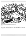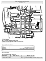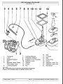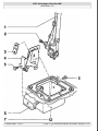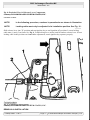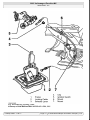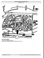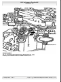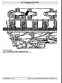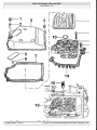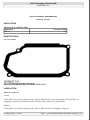
1
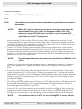
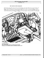
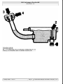
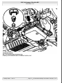
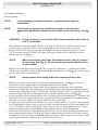
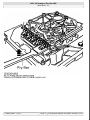
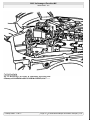
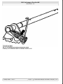
2003 Volkswagen EuroVan MV
SERVICING - A/T
2001-03 AUTOMATIC TRANSMISSIONS
Servicing - Eurovan
APPLICATION
TRANSAXLE APPLICATION
Application
Eurovan
Transaxle Model
01P
IDENTIFICATION
OIL PAN GASKET
Fig. 1: Identifying Oil Pan Gasket (01P)
Courtesy of VOLKSWAGEN UNITED STATES, INC.
LUBRICATION
SERVICE INTERVALS
Transaxle
Check fluid level at 20,000 mile intervals. Fluid is filled for life except on transaxle with code EQJ. No
changing is required. On transaxles with code EQJ, replace fluid every 40,000 miles.
Final Drive
Check fluid level at 40,000 mile intervals. Fluid is filled for life. No changing is required.
4 января 2005 г. 1:05:09
Page 1
© 2004 Mitchell Repair Information Company, LLC.
2003 Volkswagen EuroVan MV
SERVICING - A/T
CHECKING FLUID LEVELS
NOTE:
VW ATF (G 052 162 A2) is Light Yellow in color.
Transaxle
NOTE:
In the following procedures, letters and numbers in parenthesis are shown in
illustrations.
1.
NOTE:
When ATF level is checked, the seal on the level plug must always be
replaced. VAG Scan Tool (1551) and Diagnosis Cable (1551/1) are
required to check ATF fluid level. Scan tool is used to measure ATF
temperature. Follow aftermarket scan tool manufacturer instructions (if
applicable) to check AFT temperature.
Prior to checking ATF level, ensure all fuses are okay. Battery voltage must be at least 11.5 volts.
Ground connections on engine, transaxle and body must be okay. All electrical components must be
switched off. Transaxle ATF temperature must not be above about 86°F (30°C). Vehicle must be on
level surface and selector lever must be in "P" position.
2. Connect VAG 1924 ATF filling system to vehicle. Remove noise insulation tray. Connect vehicle
diagnostic, testing and information system VAS 5051. Select "08 - read measured value blocks" on
the touch screen. Select display group 005 via "Measured value block" and "Change display group
number". The first display zone shows the ATF temperature. The ATF temperature must not be more
than about 86°F (30°C) at the start of test.
3.
NOTE:
The following detailed test procedures are described for VAG Scan Tool
(1551).
Connect VAG Scan Tool (1551) and enter address word "02 Transmission electronics" and advance
until "Select function XX" is indicated on display. Measure ATF temperature in measured value
block.
4. Press keys 0 and 8. (The function "Read measured value block" is selected with 08). Confirm entry
with key Q. Press keys 0 0 5. (005 selects the "Display group number 005"). Confirm entry with key
Q. The first display zone shows the ATF temperature. The ATF temperature must not be more than
about 86°F (30°C) at the start of test. Start engine. Raise and support vehicle. Place drip tray under the
transaxle. Bring ATF to test temperature of 95-113°F (35-45°C). Remove ATF level plug (A) from
the oil pan. See Fig. 2 .
5. The ATF present in the overflow pipe (2) will run out. If ATF drips out of hole, ATF does not need to
be topped off. Install NEW seal (1) to level plug and tighten to 11 ft. lbs. (15 N.m). ATF check is
completed. Ensure sealing plug (3) and cap (4) remain closed. See Fig. 3 . If only the ATF present in
the overflow pipe runs out of hole, top off ATF.
6. To top off ATF, pry off plug securing cap (arrow) with a screwdriver. See Fig. 4 . The securing cap
locking device will be destroyed when doing this, so always replace securing cap. Pull plug out of
filler pipe. On some transaxles, a cap with a spring retainer is installed. This cap can be used again.
7.
NOTE:
An insufficient amount of ATF, as well as filling ATF to excess, affects
4 января 2005 г. 1:05:10
Page 2
© 2004 Mitchell Repair Information Company, LLC.
2003 Volkswagen EuroVan MV
SERVICING - A/T
the function of the transaxle.
Fill transaxle with ATF using VAG 1924 ATF filling system until ATF runs out of level hole. See
Fig. 5 . Install NEW seal (1) to level plug and tighten to 11 ft. lbs. (15 N.m). See Fig. 3 . Install
sealing plug (3) on filler pipe until the spring retainer lock locates, or install plug on filler pipe and
secure with a NEW cap. See Fig. 3 and Fig. 4 . Lock cap in place. The cap secures the sealing plug.
Fig. 2: Removing ATF Level Plug From Oil Pan
Courtesy of VOLKSWAGEN UNITED STATES, INC.
4 января 2005 г. 1:05:10
Page 3
© 2004 Mitchell Repair Information Company, LLC.
2003 Volkswagen EuroVan MV
SERVICING - A/T
Fig. 3: Locating Plug Seal, Overfill Pipe, Sealing Plug & Cap
Courtesy of VOLKSWAGEN UNITED STATES, INC.
4 января 2005 г. 1:05:10
Page 4
© 2004 Mitchell Repair Information Company, LLC.
2003 Volkswagen EuroVan MV
SERVICING - A/T
Fig. 4: Prying Off Plug Securing Cap
Courtesy of VOLKSWAGEN UNITED STATES, INC.
4 января 2005 г. 1:05:10
Page 5
© 2004 Mitchell Repair Information Company, LLC.
2003 Volkswagen EuroVan MV
SERVICING - A/T
Fig. 5: Filling Transaxle Using VAG 1924 ATF Filling System
Courtesy of VOLKSWAGEN UNITED STATES, INC.
Final Drive
Raise and support vehicle. Remove filler plug on side of final drive. See Fig. 6 . Gear oil level should be at
lower edge of hole. If fluid is required, add G 50, SAE 75W-90 synthetic gear oil (G 052 145 S2). Install
filler plug and tighten to 15 ft. lbs. (20 N.m).
4 января 2005 г. 1:05:10
Page 6
© 2004 Mitchell Repair Information Company, LLC.
2003 Volkswagen EuroVan MV
SERVICING - A/T
Fig. 6: Checking Final Drive Fluid Level
Courtesy of VOLKSWAGEN UNITED STATES, INC.
RECOMMENDED FLUIDS
RECOMMENDED FLUIDS
Application
Transaxle
Final Drive
(1)
Fluid Type
VW ATF (G 052 162 A2)
(1)
G 50, SAE 75W-90 (G 052 145 S2)
Synthetic oil.
FLUID CAPACITIES
TRANSAXLE FLUID CAPACITY
Application
Refill - Qts. (L)
4 января 2005 г. 1:05:10
Dry-Fill - Qts. (L)
Page 7
© 2004 Mitchell Repair Information Company, LLC.
2003 Volkswagen EuroVan MV
SERVICING - A/T
01P
3.2 (3.0)
5.6 (5.3)
FINAL DRIVE FLUID CAPACITY
Application
01P
Qts. (L)
.8 (.75)
DRAINING & REFILLING
1. To replace ATF, raise and support vehicle. Place drip tray under the transaxle. Remove ATF level
plug from the oil pan. See Fig. 2 . Remove overflow pipe through the level hole. Drain ATF. Install
overflow pipe. Screw level plug in hand-tight.
2. Fill with appropriate amount of ATF through filler pipe using VAG 1924 ATF filling system. See
FLUID CAPACITIES . See Fig. 5 . Start engine and shift transaxle through all the selector lever
positions with the vehicle stationary. Check and top off ATF level. See CHECKING FLUID
LEVELS . Tighten ATF level plug to 11 ft. lbs. (15 N.m).
ON-VEHICLE REPAIRS
NOTE:
Various components may be serviced without transaxle removal. For
servicing of these components, see appropriate component under
ADJUSTMENTS and/or REMOVAL & INSTALLATION .
ADJUSTMENTS
SELECTOR LEVER CABLE
Checking & Adjusting
NOTE:
In the following procedures, numbers in parenthesis are shown in
illustrations.
1. Remove selector lever cable locking washer (6) from lever/selector shaft. See Fig. 7 . Take selector
lever cable off lever. Move selector lever from "P" to "1" position. Selector lever mechanism and
selector lever cable must move freely. If necessary, replace selector lever cable or service selector
lever mechanism. Always replace selector lever cable locking washer on transaxle support bracket
after disassembling.
2. To adjust cable, place selector lever in "P" position. Loosen adjustment bolt (2) on selector lever in
selector lever housing. See Fig. 8 . Place selector shaft lever in "P" position on transaxle. Locking
lever must engage in park lock wheel, with both front wheels locked. Tighten adjustment bolt on
selector lever in selector lever housing to 15 ft. lbs. (20 N.m).
4 января 2005 г. 1:05:10
Page 8
© 2004 Mitchell Repair Information Company, LLC.
2003 Volkswagen EuroVan MV
SERVICING - A/T
Fig. 7: Exploded View Of Selector Mechanism Components
Courtesy of VOLKSWAGEN UNITED STATES, INC.
4 января 2005 г. 1:05:10
Page 9
© 2004 Mitchell Repair Information Company, LLC.
2003 Volkswagen EuroVan MV
SERVICING - A/T
4 января 2005 г. 1:05:11
Page 10
© 2004 Mitchell Repair Information Company, LLC.
2003 Volkswagen EuroVan MV
SERVICING - A/T
Fig. 8: Exploded View Of Selector Lever Components
Courtesy of VOLKSWAGEN UNITED STATES, INC.
LOCKING CABLE
NOTE:
In the following procedure, numbers in parenthesis are shown in illustration.
NOTE:
Locking cable must only be adjusted in its installation position. See Fig. 10 .
Shift selector lever into "P" position and turn ignition key to end (ignition off) position. Loosen locking
cable nuts (1) and (2) at frame. See Fig. 9 . Push locking lever (arrow) until it touches selector lever. Secure
locking cable in this position on frame. After adjustment, ensure ignition key operates properly.
Fig. 9: Adjusting Locking Cable
Courtesy of VOLKSWAGEN UNITED STATES, INC.
REMOVAL & INSTALLATION
4 января 2005 г. 1:05:11
Page 11
© 2004 Mitchell Repair Information Company, LLC.
2003 Volkswagen EuroVan MV
SERVICING - A/T
LOCKING CABLE
Removal & Installation
NOTE:
In the following procedures, numbers in parenthesis are shown in
illustration.
1.
NOTE:
When battery is disconnected, vehicle computer and memory systems
may lose memory data. Driveability problems may exist until computer
systems have completed a relearn cycle.
CAUTION:
Radio/cassette or radio/CD player is equipped with an anti-theft
protection circuit. Whenever battery is disconnected, radio will go into
anti-theft mode. When battery is reconnected, radio will display CODE,
and will be inoperative until proper code number is entered. Obtain
security code before disconnecting battery.
Place selector lever in "P" position. Obtain radio security code (if equipped). Disconnect negative
battery cable. Remove selector lever handle, trim, cover, cover strips and selector lever console. See
Fig. 7 .
2. Remove locking cable from frame and take off from locking lever ball head. Remove ignition switch
trim. Press locking cable clip (4) out of ignition switch support and remove locking cable (2) from ball
head. See Fig. 10 . Remove footwell vent console. Take out locking cable.
3. To install, reverse removal procedure. Ensure proper routing of locking cable when installing. Adjust
locking cable after installation. See LOCKING CABLE under ADJUSTMENTS.
4 января 2005 г. 1:05:11
Page 12
© 2004 Mitchell Repair Information Company, LLC.
2003 Volkswagen EuroVan MV
SERVICING - A/T
Fig. 10: Removing Locking Cable
Courtesy of VOLKSWAGEN UNITED STATES, INC.
4 января 2005 г. 1:05:11
Page 13
© 2004 Mitchell Repair Information Company, LLC.
2003 Volkswagen EuroVan MV
SERVICING - A/T
VALVE BODY ASSEMBLY
Removal & Installation
NOTE:
In the following procedures, numbers in parenthesis are shown in
illustrations.
NOTE:
Code letters are stamped on a metal tab located on valve body for
component identification. Metal tab must remain on the valve body. See Fig.
17 .
1.
WARNING:
Do not run engine or tow vehicle with oil pan removed or when there is
no ATF in transaxle.
Place container under the transaxle. Remove level plug (1). Remove plug seal from plug. Remove
overflow pipe (2) and allow ATF to drain. See Fig. 18 . Screw overflow pipe in onto stop.
2. Remove oil pan bolts, oil pan, gasket and AFT screen. To remove conductor strip, place Pry Bar
(3373) onto stop under the solenoid valve plug. Pull plug off with pry bar in direction of arrow.
Remove bolt (1). See Fig. 11 .
3.
NOTE:
When removing the valve body, the manual selector valve (1) remains
in valve body. See Fig. 12 . Do not interchange manual selector valves
of valve bodies.
Remove valve body bolts and valve body. Shift selector lever/shaft into "1" position. Pull manual
selector valve out until it is just possible to unhook the operating rod (2). See Fig. 12 . Secure manual
selector valve so that it cannot fall out.
4.
NOTE:
5.
6.
7.
8.
Always replace steel spring and bolt for manual selector valve.
Remove steel spring (arrow) and lever from selector shaft in transaxle. See Fig. 13 . For better
clarification, selector shaft is shown in illustration removed from transaxle.
Install steel spring and bolt to selector shaft. Do not tighten bolt at this time. Note installation
direction of sealing plug. Pull sealing plug out of housing before removing and installing free wheel,
otherwise the sealing plug and the "O" ring will be damaged. Moisten 2 new "O" rings with ATF and
install to sealing plug. Insert sealing plug in hole in transaxle housing (arrow). See Fig. 14 .
Secure operating rod onto manual selector valve by shifting selector lever/shaft into "1" position. Turn
manual selector valve so that shoulder faces operating rod. Guide operating rod with manual selector
valve into valve body. Tighten steel spring and bolt to the selector shaft.
To adjust operating rod for manual selector valve, move selector shaft to "P" position. Push operating
rod (2) with manual selector valve (1) into valve body onto stop (direction of arrow) and tighten bolt
(3) to 35 INCH lbs. (4 N.m). See Fig. 15 . Ensure selector valve is resting against the stop. Counterhold when tightening bolt. Always replace bolt and manual selector valve retaining clip.
Install valve body and bolts. Tighten bolts to 44 INCH lbs. (5 N.m). When installing conductor strip,
route conductor strip as shown. See Fig. 16 . Ensure conductor strip is not kinked or twisted. Before
installing the ATF screen, insert seal in valve body. Firmly press ATF screen onto valve body. Install
oil pan, gasket and bolts. Tighten bolts to 106 INCH lbs. (12 N.m).
4 января 2005 г. 1:05:11
Page 14
© 2004 Mitchell Repair Information Company, LLC.
2003 Volkswagen EuroVan MV
SERVICING - A/T
Fig. 11: Prying Up On Conductor Strip
Courtesy of VOLKSWAGEN UNITED STATES, INC.
4 января 2005 г. 1:05:11
Page 15
© 2004 Mitchell Repair Information Company, LLC.
2003 Volkswagen EuroVan MV
SERVICING - A/T
Fig. 12: Removing Valve Body & Unhooking Operating Rod
Courtesy of VOLKSWAGEN UNITED STATES, INC.
4 января 2005 г. 1:05:11
Page 16
© 2004 Mitchell Repair Information Company, LLC.
2003 Volkswagen EuroVan MV
SERVICING - A/T
Fig. 13: Locating Steel Spring On Selector Shaft
Courtesy of VOLKSWAGEN UNITED STATES, INC.
4 января 2005 г. 1:05:11
Page 17
© 2004 Mitchell Repair Information Company, LLC.
2003 Volkswagen EuroVan MV
SERVICING - A/T
Fig. 14: Inserting Sealing Plug
Courtesy of VOLKSWAGEN UNITED STATES, INC.
4 января 2005 г. 1:05:11
Page 18
© 2004 Mitchell Repair Information Company, LLC.
2003 Volkswagen EuroVan MV
SERVICING - A/T
Fig. 15: Adjusting Operating Rod For Manual Selector Valve
Courtesy of VOLKSWAGEN UNITED STATES, INC.
4 января 2005 г. 1:05:11
Page 19
© 2004 Mitchell Repair Information Company, LLC.
2003 Volkswagen EuroVan MV
SERVICING - A/T
Fig. 16: Installing Conductor Strip
Courtesy of VOLKSWAGEN UNITED STATES, INC.
4 января 2005 г. 1:05:11
Page 20
© 2004 Mitchell Repair Information Company, LLC.
2003 Volkswagen EuroVan MV
SERVICING - A/T
Fig. 17: Locating Valve Body Identification Tab
Courtesy of VOLKSWAGEN UNITED STATES, INC.
4 января 2005 г. 1:05:11
Page 21
© 2004 Mitchell Repair Information Company, LLC.
2003 Volkswagen EuroVan MV
SERVICING - A/T
4 января 2005 г. 1:05:12
Page 22
© 2004 Mitchell Repair Information Company, LLC.
2003 Volkswagen EuroVan MV
SERVICING - A/T
Fig. 18: Exploded View Of Valve Body Components
Courtesy of VOLKSWAGEN UNITED STATES, INC.
TORQUE SPECIFICATIONS
TORQUE SPECIFICATIONS
Application
Final Drive Filler Plug
Selector Lever Cable Adjustment Bolt
Ft. Lbs. (N.m)
15 (20)
15 (20)
INCH Lbs. (N.m)
133 (15)
106 (12)
44 (5)
ATF Level Plug
Oil Pan Bolt
Valve Body Bolt
4 января 2005 г. 1:05:12
Page 23
© 2004 Mitchell Repair Information Company, LLC.