1
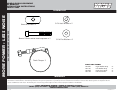
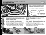
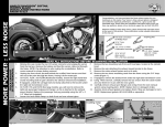
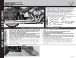
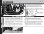
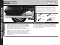
Congratulations, you have purchased the finest exhaust system for your
motorcycle on the market. Your Vance & Hines exhaust system is designed
and crafted for maximum performance, a perfect fit, a great sound and
unbeatable style. Please follow the installation instructions below and if you
have any questions, please call our technical support line at (562) 926-5291.
TOOLS
REQUIRED
Attention installer (if other than owner), please forward this instruction sheet
to the owner of this product. These instructions contain valuable information
to the end user.
STOCK EXHAUST
SYSTEM REMOVAL
MORE POWER : LESS NOISE
HONDA GL1800 GOLDWING
GL MONSTER
INSTALLATION INSTRUCTIONS
PART# 19405
Flat Blade Screwdriver
6mm Allen Wrench
10,12mm, 7/16 wrench
3/8” Ratchet &
extensions
10mm,12mm,
7/16” Deep
READ ALL INSTRUCTIONS BEFORE BEGINNING INSTALLATION
1. Loosen the 2 cap screws on each of the muffler clamps.
5. Remove the black rubber bushing from the bayonets of the
2. Remove the mounting bolt securing the muffler to the
OEM muffler (Figure 1) and save for resuse. NOTE: The
bushings may remain in the slots on the OEM heat shield,
mounting bracket located under the rear bags. NOTE:
if so carefully remove them. The tab on the bushings go in
Muffler should be supported when this bolt is removed
just as on the OEM install.
3. Carefully remove the mufflers from the vehicle.
4. Check condition of the knitted wire mesh exhaust seals
(OEM#18392-MAM-000) and replace if worn or damaged.
NOTE: The exhaust seal may stick to either the header
outlet or the inside of the muffler inlet. In either case,
carefully remove the seal, examine and set aside for re-use
or replacement.
FIGURE 1
Page 1 of 3
H480IN Rev. 1.1
FIGURE 1
FIGURE 2
Remove the 4 rubber bushings
from stock muffler bayonets,
(2 per side)
- Install on V&H heat shields
Stock mounting
boss RH
FIGURE 4
FIGURE 5
Washer/
Lock Washer
Nut Plate
Right Hand Shown - Left Opposite
1
VANCE & HINES EXHAUST
SYSTEM INSTALLATION
MORE POWER : LESS NOISE
8mm Cap Screw
2.
3.
4.
5.
6
7.
8.
Remove the muffler bodies from their packaging. Place each
muffler on a non-abrasive surface such as a blanket or carpet.
Install the black rubber bushings on the new heat shields.
Install T-Bolt band clamp over the inlet tube on each muffler so
the the body of the clamp faces the motorcycle and the nut is
down.
Install exhaust seal onto the OEM header until the seal bottoms
out on the stop.
Carefully install the muffler onto the exhaust header (using care
not to damage exhaust seal), and make sure the rubber bushings
installed on the heat shield engage the slots on the OEM heat
shield.
Install the 8mm capscrew, flat washer and lock washer through
stock mounting location and the muffler mounting bracket, install
the nut plate (flat side to muffler bracket) into the slot on the
muffler bracket. (Figure 2) Do not tighten 8mm capscrew at this
time.
Adjust muffler bodies such that the brackets are in the center of
available adjustment (Front to Rear).
Repeat for other muffler body.
9.
Looking from the rear of the motorcycle, align the muffler bodies
and tighten the T-Bolt band clamps to hold muffler alignment.
NOTE: Assistance may be required to hold alignment while the
T-bolt clamp is tightened.
10. Make sure the nut plate is fully seated in the pocket of the muffler
bracket and tighten the supplied capscrew.
11. If necessary loosen the 10mm bolt and adjust the OEM heat
shield to insure proper alignment. NOTE: Access to this bolt
may require loosening or removal of the covering body panels
(Consult OEM service manual for details).
NOTE: Any residue, oil, or fingerprints will stain the chrome finish.
Do NOT use anything abrasive to clean the pipes as it may remove
the finish. (Exhaust Care info below)
12. Be sure to tighten all hardware before starting motorcycle.
EXHAUST CARE - HELPFUL HINTS TO AVOID DISCOLORATION OF EXHAUST SYSTEM
1.
When installing a new set of pipes, make sure your hands are clean and free of oil. After
installation, thoroughly clean pipes with warm soapy water and a soft cloth. Dry with clean
towel to remove any residue before starting the motorcycle. Do NOT use anything abrasive to
clean pipes.
2.
3.
4.
Avoid long periods of idling as this can cause discoloration.
Intake leaks can cause the engine to run lean and overheat, this could lead to discoloration.
Make sure there are no exhaust leaks at the junction of the exhaust pipes and cylinder head.
We recommend replacing gaskets if they are worn.
PLEASE NOTE: Every effort is made for Vance & Hines Exhaust Systems to provide improved cornering clearance. However, due to design and space limitations on some motorcycle models, ground and
cornering clearance may not be improved and in some cases may be reduced. Be sure to follow proper installation instructions.
Page 2 of 3
H480IN Rev. 1.1
HONDA GL1800 GOLDWING
GL MONSTER
INSTALLATION INSTRUCTIONS
PART# 19405
8mm Nut Plate x 2
ALL PARTS SHOWN ARE ACTUAL SIZE
MORE POWER : LESS NOISE
PACKING LIST
8mm x 55mm socket head capscrew x 2
5/16 Lock Washer x 2
5/16 Flat Washer x 2
T-bolt Clamp x 2
PARTS NOT SHOWN:
H670RC
Right Muffler Body
H671RC
Left Muffler Body
H670HC
Right Heat Shield
H671HC
Left Heat Shield
x1
x1
x1
x1
WARRANTY
Vance & Hines exhaust systems are warranted against defects in material and workmanship for a period of 90 days from the date of purchase from an authorized dealer. This warranty does not cover
discoloration of chrome finishes. This warranty is limited to the repair or replacement of a product proven to be defective from normal use. Vance & Hines exhaust systems are designed to fit and
operate on OEM motor and chassis. This warranty does not cover any product subject to abuse, misuse, improper installation or modification.
13861 ROSECRANS AVENUE / SANTA FE SPRINGS, CA 90670
SALES: (562) 921-7461 / TECHNICAL: (562) 926-5291 / FAX: (562) 802-0110
VANCEANDHINES.COM
Page 3 of 3
H480IN Rev. 1.1