1
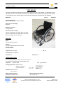
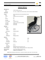
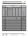
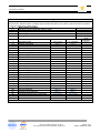
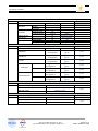
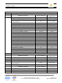
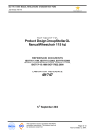
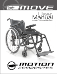
ISO 7176-1:1999 MANUAL WHEELCHAIRS – STANDARD TEST FORM Job Number: 491985-1 TEST REPORT FOR: Product Design Group Inc. Elevation Manual Wheelchair 115 kg, 253 lb REFERENCED DOCUMENTS ISO7176-1:1999, ISO7176-3:2003, ISO7176-5:2008, ISO7176-7:1998, ISO7176-8:1998, ISO7176-13:1989’ ISO7176-15:1996, ISO 7176-22:2000 LABORATORY REFERENCE 491985-1 28th October 2013 NATA Accredited Laboratory No. 2953 This document shall not be reproduced, except in full. Page 1 of 12 Tester’s Initials: RP, WW ISO 7176-1:1999 MANUAL WHEELCHAIRS – STANDARD TEST FORM Job Number: 491985-1 TEST REPORT This report may NOT be reproduced in part without written laboratory authorisation. The NovitaTech Test Laboratory has no control over the selection of test samples. Any extension of the findings of this report to cover production items must be based on the production being truly represented by the sample(s). PRODUCT Job no: 491985-1 Name and Model No: Product Design Group Elevation MWC Serial no(s) of test sample: # 64749 Maximum user mass: 115 kg, 253 lbs Documents used in testing ISO7176-1:1999, ISO7176-3:2003, ISO7176-5:2008, ISO7176-7:1998, ISO7176-8:1998, ISO7176-13:1989’ ISO7176-15:1996, ISO 7176-22:2000 SUPPLIER Name: Product Design Group Inc. Address: Unit 103, 318 East Kent Avenue South Vancouver, BC Canada V5X4N6 Telephone: 604 323 9220 Fax: n/a Contact person: Torr Brown Order No: n/a Order Date: n/a TESTING AUTHORITY NOVITA CHILDREN’S SERVICES - NOVITATECH TEST LABORATORY 171 Days Road., Regency Park, South Australia, 5010 Telephone: (08) 8243 8289 Testing supervisor: Wayne Wurfel Senior Test Technician (Authorised signatory) Fax: (08) 8243 8208 DN: CN = Wayne Wurfel, C = AU, O = NovitaTech, OU = Novitatech Test laboratory Reason: I attest to the accuracy and integrity of this document Checked: Richie Petronio Test Technician Dates of testing period: September, October 2013 Date of issue of this report: th 28 October 2013 NATA Accredited Laboratory No. 2953 This document shall not be reproduced, except in full. Page 2 of 12 Tester’s Initials: RP, WW ISO 7176-1:1999 MANUAL WHEELCHAIRS – STANDARD TEST FORM Job Number: 491985-1 PRODUCT DETAILS Manufacturer: Name Product Design Group Inc. Address Unit 103, 318 East Kent Avenue South, Vancouver BC Canada V5X4N6 Chair type: Frame: Manual wheelchair with seat elevation function. Size Frame Adult Rigid frame with seat elevation Tilt No Recline No Anti-tips Yes Push handles Single bar type Footrests Single 1 piece open loop design Armrests None fitted Headrest None fitted Seating: Backrest Width 400 mm Height 420 mm Description Sling type fabric Seat Width 400 mm Depth 420 mm Description Sling type fabric Wheels: Castor Front Rear Width 35 mm n/a Diameter 125 mm n/a Description Solid tyres n/a Drive Wheel Width 25 mm Diameter 610 mm Description Spoke wheels with pneumatic tyres Other features: Ultra-light weight, elevating seat function, folding backrest Set-up details (to ISO) As per ISO standards requirements Ambient test temperature: 21 ° C Note: Other descriptive dimensions etc. may be included in part 5 and 7 of the test report NATA Accredited Laboratory No. 2953 This document shall not be reproduced, except in full. Page 3 of 12 Tester’s Initials: RP, WW ISO 7176-1:1999 MANUAL WHEELCHAIRS – STANDARD TEST FORM Job Number: 491985-1 Clause in ISO 71761:1999 Result of Verification Test Requirement Wheelchairs - Static stability Depending on the direction of tip, wheelchairs can tip about the point of contact with the ground when the wheels are locked with respect to the frame or about the wheel axle when the wheel locks are not applied. The angle of slope on which the wheelchair will tip about the most unstable axis is measured on a test plane with an adjustable slope by increasing the angle of the test plane until the tipping angle is reached. 2.1 Test for static stability in the forward direction a) For wheelchairs without lockable front wheels, as specified in 2.1.1 & 2.1.3 only Pass Pass b) For wheelchairs with lockable front wheels, as specified in 2.1.1 to 2.1.4 - Adjustable wheelchair component Least stable Most stable Rear wheel position, fore-aft Castor attachment to frame, fore-aft Seat position, fore-aft Seat position, vertical Seat-back position, fore-aft Seat back position, recline Seat position, tilt Elevating leg rest position Forward Back Forward High Forward Upright Upright Up Back Forward Back Low Back Back Back Down 2.1.1 2.1.2 2.1.3 2.1.4 2.2 a) b) 2.2.1 2.2.2 2.2.3 2.2.4 2.3 2.3.1 2.3.2 Wheels unlocked and the wheelchair in the least stable configuration Wheels locked and the wheelchair in the least stable configuration Wheels unlocked and the wheelchair in the most stable configuration Wheels locked and the wheelchair in the most stable configuration Test for static stability in the rearward direction For wheelchairs without lockable rear wheels, as specified in 2.2.1 & 2.2.3 only For wheelchairs with lockable rear wheels, as specified in 2.2.1 & 2.2.4 Pass Pass Pass Pass Pass Pass Adjustable wheelchair component Least stable Most stable Rear wheel position, fore-aft Castor attachment to frame, fore-aft Seat position, fore-aft Seat position, vertical Seat back position, recline Seat position, tilt Seat back position, fore-aft Forward Back Back High Back Back Back Back Forward Forward Low Upright Upright Forward Wheels unlocked and the wheelchair in the least stable configuration Wheels locked and the wheelchair in the least stable configuration Wheels unlocked and the wheelchair in the most stable configuration Wheels locked and the wheelchair in the most stable configuration Test for rearward static stability with rear anti-tip devices Anti-tip device in the least stable configuration Anti-tip device in the most stable configuration NATA Accredited Laboratory No. 2953 This document shall not be reproduced, except in full. Pass Pass Pass Pass Pass Pass Page 4 of 12 Tester’s Initials: RP, WW ISO 7176-1:1999 MANUAL WHEELCHAIRS – STANDARD TEST FORM Job Number: 491985-1 Clause in ISO 7176-1:1999 2.4 Test for static stability in the sideways direction Adjustable wheelchair component 2.4.1 2.4.2 3. Result of Verification Test Requirement Rear wheel position, camber Castor attachment to frame, fore-aft Castor attachment to frame, inside-outside Seat position, fore-aft Seat position, vertical Seat position, tilt Seat back position, recline Least stable Most stable Narrowest track Back Inside Forward High Upright Upright Widest track Forward Outside Back Low Back Back Wheelchair in the least stable configuration Wheelchair in the most stable configuration Results Pass Pass Least stable Most stable Front wheels locked >10.0° Front wheels unlocked >10.0° Rear wheels locked 5.4° Rear Rear wheels unlocked 4.3° Anti-tip devices* >10.0° Left >10.0° Sideways Right >10.0° “Least stable” & “Most stable” refer to the positioning of the anti-tip devices Forward >10.0° >10.0° 7.6° 5.4° >10.0° >10.0° >10.0° ISO 7176-3:2003 Wheelchairs – Determination of effectiveness of brakes. A number of wheelchair braking operations are carried out and the resulting responses of the wheelchair are measured and observed. 2.1 Parking brakes Pass 2.2 Running brakes, normal operation n/a 2.3 Running brakes, operation by reverse command n/a 2.4 Running brakes, emergency operation n/a 2.5 Parking brakes fatigue. Pass 3. Test results For manual chairs: 3.1 Requirement Angle of the plane when movement commences The type of movement Brakes fatigue (60,000 cycles) Facing downhill Facing uphill >10° 7.6° No creep or slipping 60,000 cycles, Pass NATA Accredited Laboratory No. 2953 This document shall not be reproduced, except in full. Page 5 of 12 Tester’s Initials: RP, WW ISO 7176-1:1999 MANUAL WHEELCHAIRS – STANDARD TEST FORM Job Number: 491985-1 Clause in ISO 71761:1999 3.2 For electrically powered wheelchairs: Test plane angle Direction of travel 0° Forwards 0° Reverse 3° 3° 6° 6° 9° 9° Result of Verification Test Requirement Forwards downhill Reverse downhill Forwards downhill Reverse downhill Forwards downhill Reverse downhill Result Min braking dist, M Max speed, m/s Min braking dist, M Max speed, m/s Min braking dist, M Max speed, m/s Min braking dist, M Max speed, m/s Min braking dist, M Max speed, m/s Min braking dist, M Max speed, m/s Min braking dist, M Max speed, m/s Min braking dist, M Max speed, m/s Normal operation Reverse command Emergency power off Comments n/a n/a n/a n/a (MWC) n/a n/a n/a n/a (MWC) n/a n/a n/a n/a (MWC) n/a n/a n/a n/a (MWC) n/a n/a n/a n/a (MWC) n/a n/a n/a n/a (MWC) n/a n/a n/a n/a (MWC) n/a n/a n/a n/a (MWC) ISO 7176-5:2008 Wheelchairs – Determination of dimensions, mass & manoeuvring space 1. Wheelchair classes and occupant mass groups Not be electrically Classes of electrically powered wheelchairs: Group 1 Occupant mass groups: 2. # 1) 2) 3) 4) 5) 6) 7) 8) 9) 10) 11) 12) 13) 14) 15) 16) Group II Measurement of dimensions: Measurement position / component Full overall length Overall width Handgrip height Stowage length Stowage width Stowage height Rising Total mass Mass of heaviest part Pivot width Reversing width Turning diameter Ground clearance Required width of angled corridor Required doorway entry depth Required corridor width for side opening NATA Accredited Laboratory No. 2953 This document shall not be reproduced, except in full. powered wheelchairs A mass between 50 kg and 125 kg Record (mm) 825 mm 650 mm 590 – 865 mm 750 mm 610 mm 450 mm Not measured 12.0 kg n/a 515 radius Not measured 1150 mm 50 mm Not measured 650 mm 875 mm Page 6 of 12 Tester’s Initials: RP, WW ISO 7176-1:1999 MANUAL WHEELCHAIRS – STANDARD TEST FORM Job Number: 491985-1 ISO 7176-7:1998 Wheelchairs – Determination of seating and wheel dimensions An RLG is positioned in the wheelchair seat so as to provide repeatable deformation of the wheelchair and seat structure. Measurements of seating and wheelchair dimensions are made to reference points and planes on the RLG (Reference loader gauge) 2. Measurement procedure: 2.1 Selection of correct RLG size (Adult or child) 2.2 Positioning of the RLG 2.3 Recording of measurements 3. Result of measurements # 1) 2) 3) 4) 5) 6) 7) 8) 9) 10) 11) 12) 13) 14) 15) 16) 17) 18) 19) 20) 21) 22) 23) 24) 25) 26) 27) Dimension Seat plane angle Effective seat depth Seat width Effective seat width Seat surface height, front edge Backrest angle Backrest height Backrest width Headrest in front of backrest Headrest height above seat Footrest to seat Footrest clearance Footrest length Footrest to leg angle Leg to seat surface angle Armrest height Front of armrest to backrest Armrest length Armrest width Armrest angle Distance between armrests Front location of armrest structure Hand-rim diameter Propelling wheel diameter Horizontal displacement of wheel axle Vertical displacement of wheel axle Castor wheel diameter Fixed or min. value Maximum value Not measured 12° (Seated) 415 mm 400 mm 400 mm n/a 48.0° 370 mm 400 mm n/a n/a 425 mm 90 mm 105 mm 415 mm 400 mm 400 mm 450 mm -14.5° 370 mm 400 mm n/a n/a 385 mm 50 mm 105 mm 90° 80° n/a n/a n/a n/a n/a n/a n/a 545 mm 620 mm 1 1 1 1 Stepless 1 1 n/a n/a Not measured 105° n/a n/a n/a n/a n/a n/a n/a 545 mm 620 mm Not measured Not measured Not measured Not measured 125 mm 125 mm NATA Accredited Laboratory No. 2953 This document shall not be reproduced, except in full. No of increments Stepless n/a n/a n/a n/a n/a n/a n/a n/a n/a n/a n/a 1 Page 7 of 12 Tester’s Initials: RP, WW ISO 7176-1:1999 MANUAL WHEELCHAIRS – STANDARD TEST FORM Job Number: 491985-1 ISO 7176-8:1998 Wheelchairs – Requirements and test methods for static, impact & fatigue strengths 1. Static strength tests: Test position Force applied Remarks Downward n/a No armrests n/a Armrests Upward n/a No armrests n/a Downward 1165 N Pass Pass Upwards (each) n/a Footrests n/a n/a Upwards (single) 1010 N Pass Pass Tipping levers n/a No tipping levers n/a Handgrips n/a No handgrips n/a n/a Each (single) n/a n/a Push handles 1995 N Bar type Pass Pass 2 Impact strength tests Test position Test condition 25kg pendulum, 30°, Backrest two applications 10kg pendulum, 45°, Hand-rim two applications 10kg pendulum, 45°, Castor two applications Lateral 10kg pendulum, 45°, two applications Footrests Longitudinal 10kg pendulum, 45°, two applications Frontal 10kg pendulum, 45°, two applications Front structure Offset 10kg pendulum, 45°, two applications 3 4 Remarks 2 applications @ 30° 2 applications @ 30° 2 applications @ 30° 2 applications @ 30° 2 applications @ 30° 2 applications @ 30° 2 applications @ 30° Result Pass Pass Pass Pass Pass Pass Pass Two-drum fatigue test Test condition Speed: 1.0 metre / sec 200,000 cycles Remarks 74 RPM / 1.0 m/sec rotation speed 200,000 cycles Result Kerb drop fatigue test Test condition Height of drop: 50 mm 6,666 cycles Remarks 16 cycles / min 6,666 Cycles Result NATA Accredited Laboratory No. 2953 This document shall not be reproduced, except in full. Pass Pass Page 8 of 12 Tester’s Initials: RP, WW ISO 7176-1:1999 MANUAL WHEELCHAIRS – STANDARD TEST FORM Job Number: 491985-1 ISO 7176-22: 2000 Wheelchairs – Set-up procedures 1. Adjusting the wheelchair 2. Adjustable parameter Type of equipment Air pressure in pneumatic tyres and drive wheels Air pressure in pneumatic tyres, castors Distance between the brake blocks & their contact surfaces Drive wheel axle position, horizontal Drive wheel axle position, vertical Drive wheel camber Drive wheel track width Castor stem housing position, horizontal Castor stem housing position, vertical Castor wheel axle position, vertical Castor wheel track width Castor stem angle, fore-aft plane Castor stem angle, lateral plane Seat depth Backrest height Seat plane angle Backrest angle Leg to seat surface angle Footrest angle Footrest clearance Control device, mounting Control device, electrical settings Other electrical control devices Footrest height Final adjustments TLE067 n/a Value / position / measurement As per marking n/a TLE77 53 N engaged n/a n/a TLE148 TLE048 n/a n/a TLE148 TLE084 TLE148 TLE148 n/a n/a 90° 550 mm Fixed Fixed Fixed 445 mm Adjustable parameter 3. Backrest angle Seat plane angle Castor stem angle Distance between the brake blocks & their contact surfaces Test dummy set-up Adjustable parameter Calculated seat to back angle Dummy size Dummy seat to back angle TLE048 TLE048 Inclinometer Inclinometer Inclinometer Inclinometer n/a n/a n/a n/a TLE048 Fixed Fixed 415 mm 370 mm 12° Seated -14.5-+48° 80° - 105° 4.0° n/a n/a n/a n/a 40 – 90 mm Inclinometer Inclinometer n/a Value / position / measurement 7° 12° Fixed TLE77 53 N engaged Type of equipment Type of equipment Inclinometer TLE133 Inclinometer NATA Accredited Laboratory No. 2953 This document shall not be reproduced, except in full. Value / position / measurement 7° Adult, 115kg 8.5° Page 9 of 12 Tester’s Initials: RP, WW ISO 7176-1:1999 MANUAL WHEELCHAIRS – STANDARD TEST FORM Job Number: 491985-1 ISO 7176-15:1996 Requirements for information disclosure, documentation and labelling. Clause Requirement 5. Result Requirements for disclosure of test information in manufacturer’s specification sheets. Specification sheet must contain the following: a) b) The model designation and/or any other information that will uniquely identify the wheelchair model The mass of the test dummy used in the test Either: i) the performance values listed in Annex A, in the order and using the wording shown c) d) 6. Or: ii) if the part of ISO 7176 specifies a method of disclosure, that method shall have precedence over i) Maximum occupant mass Pass Pass Pass Pass Test report Are performance values resulting from the testing of a specific model of wheelchair to parts of ISO 7176 disclosed as specified in the relevant part of ISO 7176? 7. Pass Pass Documentation General: 7.1 a) b) c) d) e) f) g) 7.2 Is the following information available in the official language of the countries in which the wheelchair is marketed? The specification sheets A description of the intended user (eg mass, indoor / outdoor use etc.) Pass Pass Pass Either: i) details of warranty Pass Or: ii) If no warranty is provided, a statement to that effect Pass Pass A statement as to which features and options are included in specific models Information on how to get repairs and service Information as to whether a service manual is available Pass Pass A user manual User manual: At least 1 copy of the users’ manual to be supplied with the wheelchair Pass Where illustrations are used: 7.3 - Components numbered or named for positive identification - Illustrations numbered or named for positive identification Pass Pass Contents of user manual User manual to contain the following information: a) b) b) i) b) ii) b) iii) b) iv) c) c) i) c) ii) c) iii) Details of the warranty as specified in 7.1d Pass General characteristics as follows: Description of the wheelchair type, accompanied by pictures or drawings of the wheelchair & a non-technical description of how the chair is intended to be used Description of the intended user, including maximum occupant mass The environment in which the wheelchair is intended to be used and any other environmental conditions that might be harmful to the wheelchair, such as temperature and humidity If pneumatic tyres are fitted, the recommended inflation pressure or range in kPa Pass Pass Pass Pass If the wheelchair is marketed for user assembly, shall contain the following information: A list of components Information about tools or equipment needed to assemble the wheelchair Instructions on how to inspect for missing or damaged parts NATA Accredited Laboratory No. 2953 This document shall not be reproduced, except in full. Pass Pass Pass Page 10 of 12 Tester’s Initials: RP, WW ISO 7176-1:1999 MANUAL WHEELCHAIRS – STANDARD TEST FORM Job Number: 491985-1 Clause c) iv) c) v) d) Requirement Instructions for assembly, installation or removal of any parts supplied by the manufacturer Instructions on how to prepare the wheelchair for storage, shipment or travel Instructions for operation of the wheelchair as follows. Complete operating instructions for safe use including: - Instructions for operating the wheelchair on surfaces likely to be encountered by the user d) i) - Instructions for transfer of the user to and from the wheelchair - Illustrations to clarify these instructions d) ii) e) i) Any common misuse of the wheelchair known by the manufacturer that might lead to personal injury or damage to the wheelchair. Maintenance instructions accompanied by annotated illustrations and the following: - Frequency of maintenance - A list of materials necessary, including part numbers and procurement information - Identification of circumstances in which an operation should be undertaken by the manufacturer, distributor or service agent Instructions and methods of cleaning Pass Pass Pass Pass Pass - replacement and testing - Annotated illustrations of the parts (including tyres & batteries) & their locations g) iii) g) iv) g) v) g) vi) g) vii) 8. 8.1 a) b) c) d) e) 8.2 NA Pass NA For parts that the manufacturer intends to be readily replaced, the following: - Instructions for access removal f) g) g) i) g) ii) Pass Pass - order information e) iv) Pass Pass Pass Pass - Any service, maintenance &/or fault -finding for which the manufacturer intends the user to be responsible for. - Information about the types of tools or equip needed for repair and servicing e) ii) e) iii) Result Pass Pass Information on how to perform potentially hazardous maintenance operations, such as battery servicing and tyre inflation Instructions for carrying out performance checks Pass Pass Pass Pass Description of wheelchair repair procedures as follows: Identification of parts that are intended to be repaired by the user Identification of parts that have to be serviced by the manufacturer or an authorised service facility in order to maintain any warranties and serviceability Identification of any parts that can be removed and sent to the manufacturer / distributor or other party for repair. Identification of circumstances in which the manufacturer, distributor or service agent should undertake the repair A list of authorised service facilities Information on whether or not any replacement units are available Packing and shipping instructions where necessary Pass Pass Pass Pass NA Pass Permanent labelling The following information to be marked in a permanent manner on the wheelchair: The name and address of the manufacturer The model designation and serial number The year of manufacture Any driving restrictions Recommended maximum user mass Tyres to be marked with size NATA Accredited Laboratory No. 2953 This document shall not be reproduced, except in full. Pass Pass Pass NA Pass Pass Page 11 of 12 Tester’s Initials: RP, WW ISO 7176-1:1999 MANUAL WHEELCHAIRS – STANDARD TEST FORM Job Number: 491985-1 Information Disclosure: Min Max Overall length with legrest Feature 825 mm 825 mm Seat plane angle Feature Min Max 12.0° n/a Overall width 650 mm 650 mm Effective seat depth 415 mm 415 mm Folded length 750 mm Folded width 610 mm 750 mm Effective seat width 400 mm 400 mm 610 mm Seat surface height at front edge 450 mm n/a Folded height 450 mm 450 mm Backrest angle -14.5° +48.0° Total mass Backrest height 240 mm 370 mm Footrest to seat distance 385 mm 425 mm 80 mm 105 mm 12.0 kg 12.0 kg Mass of heaviest part n/a n/a Static stability downhill >10° >10° Leg to seat angle Static stability uphill 5.4° 7.6° Armrest to seat distance n/a n/a >10° >10° Front location of armrest structure n/a n/a Energy consumption n/a n/a Hand-rim diameter 545 mm 545 mm Dynamic stability uphill n/a n/a Horizontal location of axle n/a n/a Obstacle climbing n/a n/a Minimum turning radius 515 mm 515 mm Minimum braking distance from max speed n/a n/a Maximum speed forward n/a n/a Static stability sideways The sample submitted for this test satisfies the relevant requirements of ISO 7176-1:1999 (except the methods indicated in this report as “not tested” and/or tested with deviations) Yes NOTES 1U95 Uncertainty of measurements where not specified: linear 1mm, angular +- 30', force, mass 1%, temperature 1C, cycles 1 count. This means the true measurement is within the stated tolerances at least ninety five times in one hundred 2 All testing was carried out in a controlled environment laboratory using methods set out in the Standards documents, all deviations and additions to the Standards’ methods are noted in remarks. 3 All instruments either carried valid calibration certificates throughout the test period or were checked against traceable Standards before and after use. 4 The NovitaTech Test Laboratory has no control over the selection of test samples. Any extension of the findings of this report to cover production items must be based on production being truly represented by the sample(s). 5 Any non-conformances are indicated in red. _____________________________ END OF REPORT _______________________________ NATA Accredited Laboratory No. 2953 This document shall not be reproduced, except in full. Page 12 of 12 Tester’s Initials: RP, WW