1
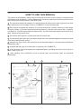
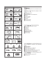
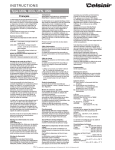
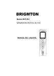
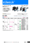
FOREWORD This Supplementary Service Manual has been prepared to introduce new service and data for the FZS600 2000. For complete service information procedures it is necessary to use this Supplementary Service Manual together with the following manual. FZS600 SERVICE MANUAL: 5DM1-AE1 FZS600 2000 SUPPLEMENTARY SERVICE MANUAL 1999 by Yamaha Motor Co., Ltd. First Edition, June 1999 Any reproduction or unauthorized use without the written permission of Yamaha Motor Co., Ltd. is expressly prohibited. EB001000 NOTICE This manual was produced by the Yamaha Motor Company primarily for use by Yamaha dealers and their qualified mechanics. It is not possible to include all the knowledge of a mechanic in one manual, so it is assumed that anyone who uses this book to perform maintenance and repairs on Yamaha scooter has a basic understanding of the mechanical ideas and the procedures of scooter repair. Repairs attempted by anyone without this knowledge are likely to render the scooter unfit for use. Yamaha Motor Company, Ltd. is continually striving to improve all its models. Modifications and significant changes in specifications or procedures will be forwarded to all authorized Yamaha dealers and will appear in future editions of this manual where applicable. NOTE: Designs and specifications are subject to change without notice. IMPORTANT INFORMATION Particularly important information is distinguished in this manual by the following. The Safety Alert Symbol means ATTENTION! BECOME ALERT! YOUR SAFETY IS INVOLVED! WARNING CAUTION: NOTE: Failure to follow WARNING instructions could result in severe injury or death to the motorcycle operator, a bystander or a person inspecting or repairing the motorcycle. A CAUTION indicates special precautions that must be taken to avoid damage to the motorcycle. A NOTE provides key information to make procedures easier or clearer. YP002000 HOW TO USE THIS MANUAL This manual is intended as a handy, easy-to-read reference book for the mechanic. Comprehensive explanations of all installation, removal,disassembly, assembly, repair and inspection procedures are laid out with the individual steps in sequential order. 1 The manual is divided into chapters. An abbreviation and symbol in the upper right corner of each page indicate the current chapter. Refer to “SYMBOLS” on the following page. 2 Each chapter is divided into sections. The current section title is shown at the top of each page, except in Chapter 3 (“Periodic Inspections and Adjustments”), where the sub-section title (-s) appear. (In Chapter 3, “Periodic Inspections and Adjustments”, the sub-section title appears at the top of each page, instead of the section title.) 3 Sub-section titles appear in smaller print than the section title. 4 To help identify parts and clarify procedure steps, there are exploded diagrams at the start of each removal and disassembly section. 5 Numbers are given in the order of the jobs in the exploded diagram. A circled number indicates a disassembly step. 6 Symbols indicate parts to be lubricated or replaced (see “SYMBOLS”). 7 A job instruction chart accompanies the exploded diagram, providing the order of jobs, names of parts, notes in jobs, etc. 8 Jobs requiring more information (such as special tools and technical data) are described sequentially. 2 4 1 8 5 6 7 3 EB003000 1 SYMBOLS 2 GEN INFO SPEC 3 4 CHK ADJ ENG 5 6 CARB COOL 7 8 CHAS ELEC Symbols 10 to 17 indicate the following. 10 9 10 11 12 13 14 15 16 17 TRBL SHTG 11 12 13 14 15 16 17 18 19 20 21 24 22 23 25 The following symbols are not relevant to every vehicle. Symbols 1 to 9 indicate the subject of each chapter. 1 General information 2 Specifications 3 Periodic inspection and adjustment 4 Engine 5 Cooling system 6 Carburetor(-s) 7 Chassis 8 Electrical system 9 Troubleshooting Serviceable with engine mounted Filling fluid Lubricant Special tool Tightening torque Wear limit, clearance Engine speed Electrical data Symbols 18 to 23 in the exploded diagrams indicate the types of lubricants and lubrication points. 18 19 20 21 22 23 Apply engine oil Apply gear oil Apply molybdenum disulfide oil Apply wheel bearing grease Apply lightweight lithium-soap base grease Apply molybdenum disulfide grease Symbols 24 to 25 in the exploded diagrams indicate the following: 24 Apply locking agent (LOCTITE) 25 Use new one CONTENTS GENERAL INFORMATION FEATURES . . . . . . . . . . . . . . . . . . . . . . . . . . . . . . . . . . . . . . . . . . . . . . . . . . . 1 SPEEDOMETER . . . . . . . . . . . . . . . . . . . . . . . . . . . . . . . . . . . . . . . . . . . 1 SPECIFICATIONS GENERAL SPECIFICATIONS . . . . . . . . . . . . . . . . . . . . . . . . . . . . . . . . . . . MAINTENANCE SPECIFICATIONS . . . . . . . . . . . . . . . . . . . . . . . . . . . . . . ENGINE . . . . . . . . . . . . . . . . . . . . . . . . . . . . . . . . . . . . . . . . . . . . . . . . . . . CHASSIS . . . . . . . . . . . . . . . . . . . . . . . . . . . . . . . . . . . . . . . . . . . . . . . . . . CABLE ROUTING . . . . . . . . . . . . . . . . . . . . . . . . . . . . . . . . . . . . . . . . . . . . . 2 3 3 4 7 PERIODIC INSPECTIONS AND ADJUSTMENTS PERIODIC MAINTENANCE/LUBRICATION INTERVALS . . . . . . . . . . . 19 CHASSIS . . . . . . . . . . . . . . . . . . . . . . . . . . . . . . . . . . . . . . . . . . . . . . . . . . . . . 21 ADJUSTING THE FRONT FORK LEGS . . . . . . . . . . . . . . . . . . . . . . . 21 CHASSIS FRONT FORK . . . . . . . . . . . . . . . . . . . . . . . . . . . . . . . . . . . . . . . . . . . . . . . . . 22 CHECKING THE FRONT FORK LEGS . . . . . . . . . . . . . . . . . . . . . . . . 23 ASSEMBLING THE FRONT FORK LEGS . . . . . . . . . . . . . . . . . . . . . . 23 ELECTRICAL SIGNAL SYSTEM . . . . . . . . . . . . . . . . . . . . . . . . . . . . . . . . . . . . . . . . . . . . . . CIRCUIT DIAGRAM . . . . . . . . . . . . . . . . . . . . . . . . . . . . . . . . . . . . . . . . . SIGNAL SYSTEM CHECK . . . . . . . . . . . . . . . . . . . . . . . . . . . . . . . . . . . CLOCK . . . . . . . . . . . . . . . . . . . . . . . . . . . . . . . . . . . . . . . . . . . . . . . . . . . . . . . FZS600 2000 WIRING DIAGRAM 26 26 28 31 FEATURES GEN INFO GENERAL INFORMATION FEATURES SPEEDOMETER 1 2 3 4 Speedometer Odometer / Tripmeter / Clock “SELECT” button “RESET” button This speedometer is equipped with: an odometer two tripmeters a clock Odometer and tripmeter modes When set to “ODO”, the motorcycle’s total mileage is indicated. When set to “TRIP 1” or “TRIP 2”, the motorcycle’s mileage since the tripmeter was last reset is indicated. Use the tripmeters to estimate how far you can ride on a tank of fuel. This information will enable you to plan fuel stops in the future. Selecting a mode Push the “SELECT” button 3 to change between the odometer mode “ODO”, the tripmeter modes “TRIP 1” and “TRIP 2”, and the clock mode in the following order: “ODO” “TRIP 1” “TRIP 2” Clock “ODO” Resetting a meter To reset either tripmeter 1 or 2 to 0.0, select either by pushing the “SELECT” button 3 and push the “RESET” button 4 for at least one second. Clock mode To change the display to the clock mode, push the “SELECT” button 3 . To change the display back to the odometer mode, push the “SELECT” button 3 . To set the clock 1. Push both the “SELECT” button 3 and “RESET” button 4 for at least two seconds. 2. When the hour digits start flashing, push the “RESET” button 4 to set the hours. 3. Push the “SELECT” button 3 to change the minutes. 4. When the minute digits start flashing, push the “RESET” button 4 to set the minutes. 5. Push the “SELECT” button 3 to start the clock. NOTE: After setting the clock, be sure to push the “SELECT” button before turning the main switch to “OFF”, otherwise the clock will not be set. –1– GENERAL SPECIFICATIONS SPEC SPECIFICATIONS GENERAL SPECIFICATIONS Model Model code: Fuel: Type Fuel tank capacity Fuel reserve amount Tire pressure: Maximum load-except motorcycle Loading condition A* front rear Loading condition B* front rear High-speed riding front rear Bulb voltage, wattage quantity: Headlight Marker light Brake/tail light Front turn signal light Rear turn signal light Meter light Indicator light Neutral indicator light High beam indicator light Oil level warning light Turn indicator light Fuel level warning light Engine temperature warning light FZS600 5DM7 5DM8 5DM9 Regular unleaded gasoline 20 L 3.5 L 187 kg 0 90 kg 225 kPa (2.25 kg/cm2, 2.25 bar) 250 kPa (2.5 kg/cm2, 2.5 bar) 90 187 kg 225 kPa (2.25 kg/cm2, 2.25 bar) 290 kPa (2.9 kg/cm2, 2.9 bar) 225 kPa (2.25 kg/cm2, 2.25 bar) 290 kPa (2.9 kg/cm2, 2.9 bar) 12 V 60 W/55 W 1 12 V 5 W 1 12 V 21 W/5 W 2 12 V 21 W 2 12 V 21 W 2 12 V 2 W 3 14 V 1.4 W 1 14 V 1.4 W 1 14 V 1.4 W 1 14 V 1.4 W 2 12 V 2 W 1 LED *Load is the total weight of cargo, rider, passenger and accessories. –2– MAINTENANCE SPECIFICATIONS SPEC MAINTENANCE SPECIFICATIONS ENGINE Item Valve spring: Free length Set length (valve closed) Compressed pressure Tilt limit Direction of winding IN/EX IN/EX IN/EX IN/EX IN/EX Carburetor: I.D. mark Main jet Main air jet Jet needle Needle jet Pilot air jet Pilot outlet Pilot jet Bypass 1 Bypass 2 Bypass 3 Pilot screw Valve seat size Starter jet Starter jet Throttle valve size Fuel level Engine idle speed Intake vacuum (M.J) (M.A.J) (J.N) (N.J) (P.A.J.1) (P.O) (P.J) (B.P.1) (B.P.2) (B.P.3) (P.S) (V.S) (G.S.1) (G.S.2) (TH.V) (F.L) (with special tool) Standard Limit 40.09 mm 34.5 mm 131.4 153.0 N (13.4 15.6 kg) SSS Clockwise 37.5 mm SSS SSS 2.5_/1.8 mm SSS 5DM1 01 (GB) (N) (SF) (DK) (D) (NL) 5DM1 01 (B) (F) (E) (P) (IRL) (GR) 5DM2 11 (D) (F) #115 #80 5D86-3/5 (GB) (N) (SF) (DK) (D) (NL) 5D86-3/5 (B) (F) (E) (P) (IRL) (GR) 5D92-3/5 (D) (F) P-0 #130 0.95 #12.5 0.9 0.8 0.8 2 1.0 0.6 0.8 #110 3.5 mm SSS 1,150 1,250 r/min 30.7 33.3 kPa (230 250 mmHg) SSS SSS –3– SSS SSS SSS SSS SSS SSS SSS SSS SSS SSS SSS SSS SSS SSS SSS SSS SSS SSS SPEC MAINTENANCE SPECIFICATIONS CHASSIS Item Standard Limit Front suspension: Front fork travel Fork spring free length Fitting length Collar length Spring Rate (K1) (K2) Stroke (K1) (K2) Optional spring Oil capacity Oil level Oil grade 120 mm 316.8 mm 309.8 mm 183 mm 7.35 N/mm (0.75 kg/mm) 13.72 N/mm (1.4 kg/mm) 0 70 mm 70 120 mm No 465 cm3 132 mm Fork oil 10W or equivalent 319 mm Drive chain: Type/manufacturer No. of links Chain free play 50VA7/DAIDO 110 30 45 mm TIGHTENING TORQUES CHASSIS Part to be tightened g Thread size M6 1.0 Holder, clutch lever 1 –4– Tightening torque Nm mkg 11 1.1 Remarks MAINTENANCE SPECIFICATIONS SPEC ELECTRICAL Item Standard Limit Ignition system: Ignition timing (B.T.D.C.) Advanced timing (B.T.D.C.) Advance type 10_/1,250 r/min 50_/4,500 r/min Digital type SSS SSS SSS T.C.I.: Pickup coil resistance T.C.I. unit model/manufacturer 189 231 Ω Y-L J4T095/MITSUBISHI SSS SSS Charging system: Type Model/manufacturer Standard output Stator coil resistance A.C. magneto F4T359 /MITSUBISHI 14 V 18 A at 5,000 r/min 0.36 0.44 Ω at 20_C/W-W SSS SSS SSS SSS Starter motor: Model/manufacturer I.D. number Output Armature coil resistance Brush overall length Brush spring pressure Commutator dia. Mica undercut (depth) Mica undercut (width) SM-13/MITSUBA SM-13 0.7 kW 0.0015 0.0025 Ω at 20_C 10 mm 7.64 10.00 N (779 1,020 gf) 28 mm 0.7 mm 0.8 mm SSS SSS SSS SSS 4 mm SSS 27 mm SSS SSS Starter relay: Model/manufacturer Amperage rating Coil winding resistance MS5F-631 /JIDECO 180 A 4.18 4.62 Ω at 20_C SSS SSS SSS Horn: Type Quantity Model manufacturer Maximum amperage Performance Coil winding resistance Plane type 1 pcs YF-12/NIKKO 3.0 A 105 113 db/2 m 1.15 1.25 Ω at 20_C SSS SSS SSS SSS SSS SSS Flasher/hazard relay: Type Model/manufacturer Self cancelling device Hazard flasher device Flasher frequency Wattage Full transistor type FE246BH/DENSO No Yes 75 95 cyl/min 21 W 2 + 3.4 W SSS SSS SSS SSS SSS SSS Thermostat switch: Model/manufacture 4BA/DENSO SSS –5– MAINTENANCE SPECIFICATIONS SPEC Item Standard limit Starting circuit cut-off relay: Model/manufacture Coil winding resistance G8R-30Y-B/OMRON 202.5 247.5 Ω at 20_C SSS SSS Fuel pump relay: Model/manufacture Coil winding resistance G8R-30Y-B/OMRON 202.5 247.5 Ω at 20_C SSS SSS 30 A 20 A 20 A 20 A 10 A 10 A 5A 30 A 20 A 10 A 5A SSS SSS SSS SSS SSS SSS SSS SSS SSS SSS SSS Amperage for individual circuit: Main Headlight Signal Ignition Fan Parking/Hazard Back up Reserve –6– CABLE ROUTING SPEC EB205000 CABLE ROUTING 1 2 3 4 5 6 7 8 9 10 Throttle cable Clutch cable Handlebar switch (left) Starter cable Main switch Main switch lead Brake hose Speed sensor lead Headlight lead Handlebar switch (right) A Use a plastic band to fasten together the handlebar switch lead (L) and the handlebar. B Use a plastic clamp to fasten together the handlebar switch lead (left), clutch cable and starter cable C Pass the speed sensor lead inside of the clamp code. –7– D Pass the brake hose out side of the speed sensor lead, then use a plastic clamp to fasten them. CABLE ROUTING 1 2 3 4 5 6 7 8 9 10 11 Main switch lead Handlebar switch lead (left) Clutch cable Starter cable Rectifier/ regulator Horn lead Box Air guide plate Fan motor lead High tension code Relay assembly 12 13 14 15 16 17 18 19 20 21 22 Flasher leray Battery Starter relay Battery positive (+) lead Seat lock cable Seat lock stay Cross tube AC magneto lead Starter motor lead Air filter drain hose Neutral switch –8– 23 24 25 26 27 28 29 30 31 32 33 SPEC Sidestand switch lead Neutral switch lead Oil level switch lead Radiator Rectifier/ regulator lead Horn Speed sensor lead Brake hose Horn lead Horn bracket Rear fender CABLE ROUTING 34 35 36 37 38 39 40 41 42 43 44 Wire harness Relay Fuse box To front brake switch To battery negative (–) lead To starter relay Starter motor lead Pickup coupler Sidestand switch coupler Oil level / neutral switch coupler AC magneto coupler 45 Oil level / neutral switch lead A Use a plastic clamp to fasten the handlebar switch lead (left), main switch lead, clutch cable and starter cable to the frame. B Pass the fan motor lead through the guide gear, then into the box. C Use a plastic clamp to fasten the horn lead and air guide plate to the frame. –9– SPEC D When installing the plug cap, the high tension code should be facing the inside of the body. E Pass the wire harness, starter motor lead, AC magneto lead, sidestand switch lead and oil / neutral switch lead over the cross tube. F Use a plastic clamp to fasten together the wire harness and the frame. CABLE ROUTING G Use a plastic clamp to fasten together the wire harness and the frame. H Push couplers into the lock stay of the frame after connecting wires. I Use a plastic band to fasten together wireharness, starter motor lead, AC magneto lead, sidestand switch lead and oil level / neutral switch lead, then hold SPEC the clamp to the frame bracket. L Use a steel holder to fasten toPosition the band end to out side gether the AC magneto lead, of chassis. sidestand lead and oil level / neuJ Use a plastic locking tie to fasten tral switch lead. the starter motor lead, AC mag- M Pass the air cleaner drain hose neto lead, sidestand switch lead in front of the rear arm pivot shaft and oil level / neutral switch lead and back of the cross tube. to the frame bracket. Cut off the N Pass the air cleaner drain hose excess end of the tie. through the pipe holder of rear K Pass the air cleaner drain hose shock absorber bracket, then draw through the engine clamp. it out to the left side of the body. –10– CABLE ROUTING O Use a plastic clamp to fasten together the sidestand switch lead and the frame. P Pass the sidestand switch lead through the bottom of the coolant pipe. Q Do not loosen the fan motor lead here. R Pass the clutch cable and starter cable outside of high tension code#1. S Use a steel holder to fasten together the speed sensor lead and outer tube. T Use a plastic clamp to fix the speed sensor lead at 3 points after running the lead along the outside of the brake hose. First. Fasten the bottom end of the speed sensor lead without loosening. Second. Fasten the lead several –11– SPEC times from the bottom end by running along the brake hose. U Pass the hom lead under the horn bracket, then connect it at the back of the horn. V Pass only the starter lead through the bottom of the joint of wire harness. CABLE ROUTING 1 2 3 4 5 6 7 8 9 10 11 12 13 Rear brake switch lead Battery Reservoir tank over flow hose Cross tube Battery negative (–) lead Reservoir tank hose Air filter To fuel tank Fuel tank breather hose Fuel tank drain hose T.P.S. lead Box Speed sensor lead 14 15 16 17 18 19 20 21 22 23 Handlebar switch lead (right) Throttle cable Brake hose Guide wire Headlight lead Main switch lead Reservoir tank Air filter box bracket Swingarm bracket Engine bracket –12– SPEC A Pass the fuel tank drain hose, fuel tank breather hose and reservoir tank over flow pipe between the rear arm and the engine crankcase. B Pass the fuel tank drain hose and fuel tank breather hose between air filter joint #3 and #4. After installing the fuel tank, pull it down toward the air filter joint so that there will be no bend of loosening between them. CABLE ROUTING SPEC C Pass the T.P.S lead as shown, F Pass the throttle cable, with the J Pass the throttle cable under the then install cover to the air filter pull side up, through the center box. case. of the clamp. K Pass the reservoir tank over flow D Use a plastic clamp to fasten to- G Pass the throttle cable through hose and fuel tank drain hose gether the throttle cables, headthe guide wire installed to the through the cable holder. light lead, handlebar switch handle crown. L To coolant reservoir tank. (right) and speed sensor lead. H To front cowling. M Pass the battery negative (–) E Use a plastic locking tie to fasten I Pass the main switch lead under lead inside of the reservoir hose. the handlebar switch (right) and the throttle cables, headlight N Use the plastic clamp to fasten brake hose to the right front fork lead, handlebar switch lead together the rear brake switch inner tube. (right) and speed sensor lead, lead and the frame. then insert it right side of the box. The latch of the clamp must face the outside of the body. –13– CABLE ROUTING O Pass the battery negative lead and rear brake switch lead inside the air filter bracket of the frame. P Pass the reservoir tank over flow pipe between the air filter case and cross tube, and then outside of engine bracket. Q Use a clamp to fasten together the coolant reservoir hose and the bracket rear arm. –14– SPEC CABLE ROUTING 1 2 3 4 5 6 7 8 9 10 11 12 Throttle cable Speed sensor lead Handlebar switch lead (right) Headlight lead Thermostat housing Carburetor heater hose Reservoir tank hose Throttle cable Fuel pump Fuel filter Fuel tank breather hose Fuel tank drain hose 13 14 15 16 17 18 19 20 21 22 23 24 Pipe Fuel hose T.P.S lead Fuel pipe Fuel sender, coupler Battery negative (–) lead Battery Rear brake hose Rear brake reservoir tank Rear brake switch lead Fuse box Seat lock cable –15– 25 26 27 28 29 30 31 32 33 34 35 36 SPEC Ignitor Rear turn signal light lead (right) Taillight lead Rear turn signal light lead (left) Taillight bracket Starter motor lead Starter relay Relay Relay assembly Wire harness Fuel pump lead coupler Ignition coil CABLE ROUTING 37 38 39 40 41 42 43 44 45 46 47 48 Clutch cable Starter cable Ground lead Box Fan motor lead Rectifier/ regulator lead Handlebar switch lead (left) Main switch lead Wire harness 13 To taillight Rear fender Clamp SPEC A Tighten the ground lead and the the coolant reservoir tank, bethermostat housing together tween the reservoir hose and the with a bolt. battery, then are connected at B Pass the reservoir hose left side the right side of the battery. of thermo stat housing. G Pass the rear flasher lead (R) C Do not fasten the high tension through the rear fender. cord #4 with locking tie. H Pass the rear flasher lead (L) D Use a plastic band to fasten the through the rear fender. high tension cord #3, #4. I Pass the wire harness through E Fuel pump lead comes over. the groove of the rear fender. F Pass the rear brake switch lead J Wire harness shouldn’t come and battery negative lead under top of the rear fender rib. –16– CABLE ROUTING K Pass the wire harness inside of P Pass the fuel pump lead between the ignition coil and fuel filthe rear fender rib. ter, then push under. L Pass the wireharness under the Q Use a plastic clamp to fasten tostarter relay. gether the wire harness and M Pass the starter motor lead unstay. der the joint of the harness, then R Pass the carburetor inlet hose unpull upward. der the high tension cord #2, #4. N Set the fuel sender coupler in the S Use a clamp to fasten the clutch cross pipe of the frame. cable and starter cable. O Use a plastic clamp to fasten together the wire harness and T Use a plastic clamp to fasten high tension code #2, and #4. cross pipe of the frame. –17– SPEC U Set the clamp, which is fixed to the wire harness, in T-stud of the frame. V Put the wire harness into the box through the groove at the back, then connect it in the box. CABLE ROUTING W Pass the rectifier / regulator lead, fan motor lead, handlebar switch lead (left), main switch lead, headlight lead, handlebar switch lead (right) and speed sensor lead through front side of the box, then connecte each coupler in the box. X Use a plastic clamp to fasten the wire harness after passing always under the taillight bracket. Y Align the connector position of rear turn signal light leads (left and right), then bend the rear –18– SPEC PERIODIC MAINTENANCE/LUBRICATION INTERVALS CHK ADJ EB3000000 PERIODIC INSPECTIONS AND ADJUSTMENTS PERIODIC MAINTENANCE/LUBRICATION INTERVALS EVERY NO. ITEM CHECKS AND MAINTENANCE JOBS 1 * Fuel line Check fuel hoses for cracks or damage. Replace if necessary. 2 * Fuel filter Check condition. Replace if necessary. Spark plugs Check condition. Clean, regap or replace if necessary. Valves Check valve clearance. Adjust if necessary. Air filter Clean or replace if necessary. Clutch Check operation. Adjust or replace cable. 3 4 * 5 6 INITIAL (1,000 km) 6,000 km or 6 months (whichever comes first) 12,000 km or 12 months (whichever comes first) √ √ √ √ √ √ Every 42,000 km or 42 months (whichever comes first) √ √ √ √ √ 7 * Front brake Check operation, fluid level and vehicle for fluid leakage. (See NOTE) Correct accordingly. Replace brake pads if necessary. √ √ √ 8 * Rear brake Check operation, fluid level and vehicle for fluid leakage. (See NOTE) Correct accordingly. Replace brake pads if necessary. √ √ √ 9 * Wheels Check balance, runout and for damage. Rebalance or replace if necessary. √ √ 10 * Tires √ √ 11 * Wheel bearings Check bearing for looseness or damage. Replace if necessary. √ √ 12 * Swingarm Check swingarm pivoting point for play. Correct if necessary. Lubricate with molybdenum disulfide grease every 24,000 km or 24 months (whichever comes first). √ √ 13 Drive chain Check chain slack. Adjust if necessary. Make sure that the rear wheel is properly aligned. Clean and lubricate. 14 * Steering bearings Check bearing play and steering for roughness. Correct accordingly. Lubricate with lithium soap base grease every 24,000 km or 24 months (whichever comes first). √ √ 15 * Chassis fasteners Make sure that all nuts, bolts and screws are properly tightened. Tighten if necessary. √ √ Check tread depth and for damage. Replace if necessary. Check air pressure. Correct if necessary. –19– Every 1,000 km and after washing the motorcycle or riding in the rain PERIODIC MAINTENANCE/LUBRICATION INTERVALS CHK ADJ EVERY NO. ITEM CHECKS AND MAINTENANCE JOBS INITIAL (1,000 km) 6,000 km or 6 months (whichever comes first) 12,000 km or 12 months (whichever comes first) √ √ √ √ 16 Sidestand / centerstand S Check operation. S Lubricate and repair if necessary. 17 * Sidestand switch S Check operation. S Replace if necessary. 18 * Front fork S Check operation and for oil leakage. S Correct accordingly. √ √ 19 * Rear shock absorber assembly S Check operation and shock absorber for oil leakage. S Replace shock absorber assembly if necessary. √ √ 20 * Rear suspension relay arm and connecting arm pivoting points S Check operation. S Lubricate with molybdenum disulfide grease every 24,000 km or 24 months (whichever comes first). √ √ 21 * Carburetors S Check engine idling speed, synchronization and starter operation. S Adjust if necessary. √ √ √ 22 Engine oil S Check oil level and vehicle for oil leakage. S Correct if necessary. S Change. (Warm engine before draining.) √ √ √ 23 Engine oil filter cartridge S Replace. √ 24 * Cooling system S Check coolant level and vehicle for coolant leakage. S Correct if necessary. S Change coolant every 24,000 km or 24 months (whichever comes first). √ √ √ √ * Since these items require special tools, data and technical skills, they should be serviced by a Yamaha dealer. NOTE: D The air filter needs more frequent service if you are riding in unusually wet or dusty areas. D Hydraulic brake system S When disassembling the master cylinder or caliper, always replace the brake fluid. Check the brake fluid level regularly and fill as required. S Replace the oil seals on the inner parts of the master cylinder and caliper every two years. S Replace the brake hoses every four years or if cracked or damaged. –20– ADJUSTING THE FRONT FORK LEGS CHK ADJ EAS00152 CHASSIS ADJUSTING THE FRONT FORK LEGS The following procedure applies to both of the front fork legs. WARNING Always adjust both front fork legs evenly. Uneven adjustment can result in poor handling and loss of stability. Securely support the motorcycle so that there is no danger of it falling over. CAUTION: Grooves are provided to indicate the adjustment position. Never go beyond the maximum or minimum adjustment positions. 1. Adjust: spring preload a. Turn the adjusting bolt 1 in direction a or b. Direction a Spring preload is increased (suspension is harder). Direction b Spring preload is decreased (suspension is softer). Adjusting positions Standard: 5 Minimum: 7 Maximum: 1 –21– FRONT FORK CHAS CHASSIS FRONT FORK 30 Nm (3.0 mkg) 30 Nm (3.0 mkg) 7 Nm (0.7 mkg) Order Job name/Part name Q’ty Remove the parts in the order listed. Refer to “FRONT WHEEL AND BRAKE DISCS” section. Refer to “FRONT AND REAR BRAKES” section. Removing the front fork Front wheel Front brake calipers 1 2 3 4 5 Front fender Bolt (upper bracket) Cap bolt Bolt (lower bracket) Front fork assembly (left/right) Remarks 1 2 2 2 1/1 –22– Loosen Refer to “REMOVING/ Loosen INSTALLING THE FRONT Loosen FORK LEGS” section. Refer to “REMOVING/INSTALLING THE FRONT FORK LEGS” section. For installation, reverse the removal procedure. FRONT FORK CHAS 23 Nm (2.3 mkg) 30 Nm (3.0 mkg) Order 1 2 3 4 5 6 7 8 9 10 11 12 13 Job name/Part name Disassembling the front fork Cap bolt O-ring Spacer Washer Front fork spring Dust seal Oil seal clip Bolt Gasket Damper rod/rebound spring Inner tube/Inner tube bushing Oil seal Washer Q’ty Remarks Disassembly the parts in the order listed. 1 1 1 1 1 1 1 1 1 1/1 1 1 1 –23– Refer to “ASSEMBLING THE FRONT FORK LEGS” section. Refer to “DISASSEMBLING/ ASSEMBLING THE FRONT FORK LEGS” section. FRONT FORK CHAS 23 Nm (2.3 mkg) 30 Nm (3.0 mkg) Order 14 15 Job name/Part name Outer tube bushing Oil flow stopper Q’ty 1 1/1 –24– Remarks Refer to “ASSEMBLING THE FRONT FORK LEGS” section. For assembly, reverse the disassembly procedure. FRONT FORK CHAS CHECKING THE FRONT FORK LEGS 1. Check: cap bolt O-ring 1 Damage/wear Replace. EB703700 ASSEMBLING THE FRONT FORK LEGS 1. Fill: front fork leg (with the specified amount of the recommended fork oil) Quantity (each front fork leg) 0.465 L Yamaha fork and shock oil 10 W or equivalent. Front fork leg oil level a (from the top of the inner tube, with the inner tube fully compressed and without the fork spring) 132 mm NOTE: While filling the front fork leg, keep it upright. After filling, slowly pump the front fork leg up and down to distribute the fork oil. –25– SIGNAL SYSTEM EB806000 ELECTRICAL SIGNAL SYSTEM CIRCUIT DIAGRAM –26– ELEC SIGNAL SYSTEM 3 4 6 35 40 41 42 43 52 60 Main switch Battery Fuse (main) Flasher relay Turn switch Hazard switch Front turn signal light Rear turn signal light Fuse (signal) Relay 2 –27– ELEC SIGNAL SYSTEM ELEC SIGNAL SYSTEM CHECK EB806023 1. If the turn signal light and/or turn indicator light fails to blink: 1. Bulb and bulb socket NO CONTINUITY S Check the bulb and bulb socket for continuity. Replace the bulb and/or bulb socket. CONTINUITY 2. Turn switch S Disconnect the left handlebar switch couplers from the wire harness. S Set the hazard switch “OFF” S Check for continuity as follows: Brown/White 1 – Chocolate 2 Brown/White 1 – Dark green 3 NO CONTINUITY Replace the left handlebar switch. CONTINUITY 3. Hazard switch S Disconnect the left handlebar switch couplers from the wire harness. S Set the turn switch “Neutral position” S Check for continuity as follows: Brown/White 1 – Chocolate 2 Brown/White 1 – Dark green 3 Chocolate 2 – Dark green 3 NO CONTINUITY Replace the left handlebar switch. CONTINUITY : –28– SIGNAL SYSTEM ELEC : 4. Voltage S Connect the pocket tester (DC 20 V) to the flasher relay coupler. Tester (+) lead Brown terminal 1 Tester (–) lead Frame ground OUT OF SPECIFICATION S Turn the main switch to “ON”. S Check the voltage (12 V) of the “Brown” 1 lead at the flasher relay terminal. MEETS SPECIFICATION The wiring circuit from the main switch to the flasher relay connector is faulty, repair it. 5. Voltage S Connect the pocket tester (DC 20 V) to the flasher relay coupler. Tester (+) lead Brown/White terminal 1 Tester (–) lead Frame ground S Turn the main switch to “ON”. S Turn the turn switch to “L”/“R” or push the hazard switch. S Check the voltage (12 V) on the “Brown/White” 1 lead at the flasher relay terminal. OUT OF SPECIFICATION The flasher relay is faulty, replace it. MEETS SPECIFICATION : –29– ELEC SIGNAL SYSTEM : A 6. Voltage B S Connect the pocket tester (DC 20 V) to the bulb socket connector. A Flasher light B Turn indicator light 1 2 At the flasher light (left): Tester (+) lead Chocolate lead 1 Tester (–) lead Frame ground At the flasher light (right): Tester (+) lead Dark green lead 2 Tester (–) lead Frame ground OUT OF SPECIFICATION S Turn the main switch to “ON”. S Turn the turn switch to “L”/“R” or push the hazard switch. S Check the voltage (12 V) of the “Chocolate” lead or “Dark green” lead on the bulb socket connector. The wiring circuit from the left handlebar switch to the bulb socket connector is faulty, repair it. MEETS SPECIFICATION This circuit is not faulty. –30– CLOCK ELEC CLOCK EAS00805 The clock fails to come on. 1. Voltage Connect the pocket tester (DC 20 V) to the clock coupler. Tester (+) read Brow 1 Tester (–) read Frame ground OUT OF SPECIFICATION Turn the main switch to “ON”. Check the voltage (12 V) on the “Brown” 1 lead at the clock terminal. MEETS SPECIFICATION The wiring circuit from the main switch to the clock coupler is faulty, repair it. 2. Clock OUT OF SPECIFICATION Check that the clock is operating properly. When setting the clock after its power source has been disconnected (e.g., when the battery is removed), first set the clock to 1:00 AM and then to the correct time. The clock is faulty, replace it. MEETS SPECIFICATION This circuit is not faulty. –31– FZS600 2000 WIRING DIAGRAM 1 2 3 4 5 6 7 8 9 10 11 12 13 14 15 16 17 18 19 20 21 22 23 24 25 26 27 28 29 30 COLOR CODE B ...... Br . . . . . Ch . . . . Dg . . . . G ..... Gy . . . . L ...... Black Brown Chocolate Dark green Green Gray Blue P ...... Lg . . . . . O ..... R...... Sb . . . . . W ..... Y ...... Pink Light green Orange Red Sky blue White Yellow B/L . . . . B/R . . . B/W . . . B/Y . . . Br / L . . . Br / W . . G/R . . . Black / Blue Black / Red Black / White Black / Yellow Brown / Blue Brown / White Green / Red G/W . . . G/Y . . . L/B . . . . L/R . . . L/W . . . L/Y . . . . R/B . . . Green / White Green / Yellow Blue / Black Blue / Red Blue / White Blue / Yellow Red / Black R/W . . . R/Y . . . W/B . . . W/G . . . W/R . . . Y/B . . . Y/R . . . Red / White Red / Yellow White / Black White / Green White / Red Yellow / Black Yellow / Red A.C. magneto Rectifier/ regulator Main switch Battery Fuse (back up) Fuse (main) Starter relay Starter motor Starting circuit cut-off relay Fuel pump relay Ignitor unit Ignition coil Spark plug Pick up coil Throttle position sensor Neutral switch Speed sensor Fuel sender Thermo switch (engine temperature) Diode Fuel pump Sidestand switch Speedometer Tachometer Fuel meter Fuel level warning light Engine temperature warning light Neutral indicator light Oil level warning light High beam indicator light 31 32 33 34 35 36 37 38 39 40 41 42 43 44 45 46 47 48 49 50 51 52 53 54 55 56 57 58 59 60 Turn indicator light Meter light Clutch switch Oil level switch Flasher relay Horn Pass switch Dimmer switch Horn switch Turn switch Hazard switch Front turn signal light Rear turn signal light Headlight Tail/ Brake light Auxiliary light Fan motor Thermo switch (fan motor) Fuse (fan motor) Fuse (head light) Rear brake switch Fuse (signal) Front brake switch Light switch Engine stop switch Starter switch Fuse Alarm Fuse (parking) Relay 2