1
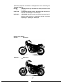
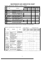
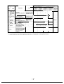
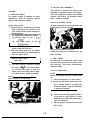
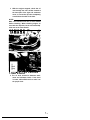
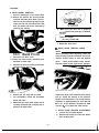
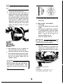
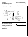
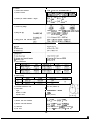
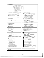
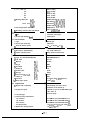
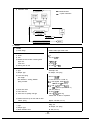
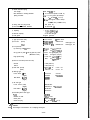
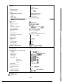
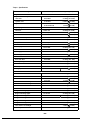
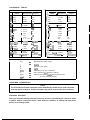
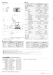
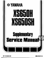
INDEX
This manual has been combined with previous
service manuals to provide complete service
information for: XS650H/SH.
Please read and give special consideration to
the “NOTICE” on the preceding page for your
safety.
XS650H/SH SUPPLEMENT
XS650 MODELS 1978-80
FOREWORD
This Supplementary Service Manual has been prepared to introduce new
service and new data for the XS650H/XS650SH. For complete information
on service procedure, it is necessary to use this Supplementary Service
Manual together with following manuals:
’ XS650E Service Manual (LIT-11616-00-76)
! XS650SE Supplementary Service Manual (LIT-11616-01-08)
’ XS650SF/2F Supplementary Service Manual (LIT-11616-01-65)
XS650G/SG Supplementary Service Manual (LIT-1 1616-01-75)
I
1
SERVICE DEPT.
INTERNATIONAL DIVISION
YAMAHA MOTOR CO., LTD.
NOTE:
This Supplementary Service Manual contains information regarding periodic
maintenance to the emission control system for the XS650H/XS650SH.
Please read this material carefully.
NOTICE
This manual was written by the Yamaha Motor Company primarily for use
by Yamaha dealers and their qualified mechanics. It is not possible to put
an entire mechanic’s education into one manual, so it is assumed that
persons using this book to perform maintenance and repairs on Yamaha
motorcycles have a basic understanding of the mechanical concepts and
procedures inherent to motorcycle repair technology. Without such knowledge, attempted repairs or service to this model may render it unfit for use
and/or unsafe.
This model has been designed and manufactured to perform within certain
specifications in regard to performance and emissions. Proper service with
the correct tools is necessary to ensure that the motorcycle will operate as
designed. If there is any question about a service procedure it is imperative
that you contact a Yamaha dealer before continuing. Before attempting any
service, check with your Yamaha dealer for any service information changes
that apply to this model: This policy is intended to provide the customer
with the most satisfaction from his motorcycle and to conform with federal
environmental quality objectives.
Yamaha Motor Company, Ltd. is continually striving to further improve all
models manufactured by Yamaha. Modifications and significant changes in
specifications or procedures will be forwarded to all Authorized Yamaha
dealers and will, where applicable, appear in future editions of this manual.
I -
Particularly important information is distinguished in this manual by the
following notations:
NOTE :
A NOTE provides key information to make procedures easier
or clearer.
CAUTION:
A CAUTION indicates special procedure that must be followed to avoid damage to the motorcycle.
A WARNING indicates special procedures that must be folWARNING:
lowed to avoid injury to a motorcycle operator or person
inspecting or repairing the motorcycle.
Starting Serial Number
XS650H
H . . . . . . . . . . . . . 4N9-000101
XS650SH
H . . . . . . . . ..__. 4M4-000101
MAINTENANCE AND LUBRICATION CHART
PERIODIC MAINTENANCE EMISSION CONTROL SYSTEM
- 3
c
t
c
B. PICK-UP COIL ASSEMBLY
The method of mounting the pick-up coil
assembly is changed for easier service work.
Thus, the followings “Pick-up coil assembly
removal” and “Pick-up coil assembly reinstallation” should be changed.
*ENGINE
A. IGNITION TIMING
The ignition system is modified for easier
maintenance. Thus, the following “ignition
timing check” should be changed,
Pick-up coil assembly removal
Remove the pick-up coil securing screws and
remove the pick-up coil assembly.
Ignition timing check
1. Ignition timing is checked with a timing
light by observing the position of the
rotor pointer and the marks stamped on
the timing plate.
The timing plate is marked as follows.
“ll” Firing range for No. 1 (L.H.)
“T”
Top Dead Center for No. 1,
fL.H.1 cylinder
2. Connect the timing light to the left
cylinder spark plug lead wire.
3. Start the engine and keep the engine
speed as specified. Use a tachometer to
check the engine speed.
L_
4.
Pick-up coil assembly reinstallation
Install the pick-up coil assembly on to the
stator assembly.
C. FUEL LEVEL
The carburetor is furnished with a drain screw
to provide easy access to service work. Thus,
the following “Fuel level measurement”
should be added.
Specified engine speed:
1,200 r/min
The rotor pointer should be within
the limits of ” fl ” on the timing plate.
If it exceeds the limits or does not
steady, check the timing plate for tightness and/or ignition system for damage.
Fuel level measurement
NOTE:
Before checking the fuel level, note the following:
1. Place the motorcycle on a level surface.
2. Adjust the motorcycle position by placing a suitable stand or a garage jack
under the engine so that the carburetor
is positioned vertically.
NOTE:
Ignition timing is not adjustable.
1.
2.
-5
Connect the level gauge (special tool) or
a vinyl pipe of 6 mm (0.24 in) in inside
diameter to the float bowl nozzle left or
right side carburetor.
Set the gauge as shown and loosen the
drain screw.
Fuel level:
1 f 1 mm (0.04? 0.04 in) above
from the carburetor mixing chamber
body edge.
YL___-A
3. Start the engine and stop it after a few
minutes of run. This procedure is necessary to obtain the correct fuel level.
NOTE:
Make sure the fuel petcock is “ON” or “RES”
oosition.
4.
6. If the fuel level is incorrect, remove the
carburetor assembly from the motorcycle and check the fuel valve(s) and
float assembly(s) for damage.
7. If no damage is found, correct the fuel
level by slightly bending the float arm
tang. Recheck the fuel level.
Note the fuel level and bring the gauge
to the other end of the carburetor line
and repeat step 3 above. Note the fuel
level again and compare it with the
previous gauge reading. They should be
equal. If not, place a suitable size of
wooden piece or the. alike under the
center stand and adjust.
D. ENGINE OIL LEVEL MEASUREMENT
1. Place the motorcycle on the center stand.
Warm up the engine for several minutes.
5. Check the fuel level one by one. The
level should be in the specified range.
NOTE:
Be sure the motorcycle is positioned straight
up when checking the oil level; a slight tilt
toward the side can produce false readings.
-6Y
2
With the engine stopped, check the oil
level through the level window located at
the lower part of the right side crankcase
cover, or screw the dip stick completely
out and then the stick in the hole.
NOTE:
Wait a few minutes until the oil level settles
before checking. When checking engine oil
level with the dip stick, let the unscrewed dip
stick rest on the case threads.
1. Dip stick
2. Maximum level
3. Minimum level
3. The oil level should be between maximum and minimum levels. If the level
is lower, add sufficient oil to raise it to
the proper level.
l-
*CHASSIS
A. REAR WHEEL REMOVAL
1. Place the motorcycle on the center stand.
2. Remove the tension bar and the brake
rod from the brake shoe plate. The tension bar can be removed by removing the
cotter pin and nut from the tension bar
bolt. The brake rod can be removed by
removing the adjuster.
b. Make sure the axle nut is properly
torqued and a new cotter pin is installed.
15.0 m-kg (108.5 ft-lb)
c. Adjust the drive chain.
8. DRIVE CHAIN TENSION CHECK
1. Adjusfer
2. Brake rod
3. Tenrio” bar
3. Disconnect the drive chain.
4. Loosen the chain tension adjusting nuts
and bolts on both sides.
5. Remove the axle nut cotter pin and axle
nut. Discard the old pin.
Remove the axle shaft and the wheel.
For reassembly, follow the procedure
below with care:
a. Make sure the drive chain master link is
correctly installed with rounded end in
direction of chain travel.
6.
7.
NOTE:
Before checking and/or adjusting, rotate rear
wheel through several revolutions and check
tension several times to find the tightest
Check and/or adjust chain tension
point.
with rear wheel in this “tight chain” position.
Inspect the drive chain with the center stand
put up. Check the tension at the position
shown in the illustration. The normal vertical
deflection is approximately 20 - 30 mm (0.8
- 1.2 in). If the deflection exceeds 20 - 30
mm (0.8 - 1.2 in) adjust the chain tension.
C. DRIVE CHAIN TENSION ADJUSTMENT
1. Loosen the rear brake adjuster.
2. Remove the cotter pin of the rear wheel
axle nut with pliers.
NOTE:
The rear wheel axle nut is located on the right
side.
3.
4.
Loosen the rear wheel axle nut.
Loosen the lock nuts on each side. To
tighten chain turn chain puller adjusters
clockwise. To loosen chain turn adjusters counterclockwise and push wheel
forward. Turn each adjuster exactly the
same amount to maintain correct axle
alignment. (There are marks on each
side of the rear arm and on each chain
puller; use them to check for proper
alignment.)
7. In the final step, adjust the play in the
brake pedal.
D. REAR BRAKE ADJUSTMENT
1. Pedal height
a. Loosen the adjuster lock nut (for pedal
height).
b By turning the adjuster bolt clockwise
or counterclockwise, adjust the brake
pedal position so that its top end is
approx. 12 - 18 mm (0.47 - 0.71 in)
below the footrest top end.
C
Secure the adjuster lock nut.
-WARNING:
After adjusting the pedal height, the brake
pedal free play should be adjusted.
1. LO& nut
2. Adj”rter
3. Marks for align
4. near wheel axle nut
5. cotter pin
5.
6.
2. Free play
Turn the adjuster on the brake rod
clockwise or counterclockwise to provide the brake pedal end with a free play
of 20- 30 mm (0.79 - 1.18 in).
After adjusting, be sure to tighten the
lock nuts and the rear wheel axle nut.
Insert the cotter pin into the rear wheel
axle nut and bend the end of the cotter
pin (if the nut notch and the cotter pin
hole do not match, tighten the nut
slightly to match).
-CAUTION:
Excessive chain tension will overload the
engine and other vital parts; keep the tenAlso,
sion within the specified limits.
replace the rear axle cotter pin with a new
one.
1
9
E. REAR BRAKE LINING INSPECTION
The specified thickness of the brake lining is 4
mm (0.16 in). The lining should be replaced
when it wears to less than 2 mm (0.079 in).
To check, see the wear indicator position
while depressing the brake pedal.
*ELECTRICAL
STARTING CIRCUIT CUT-OFF SYSTEM
The starting circuit cut-off system is employed. Hence, the following description.
Description
This model is equipped with a starting circuit
cut-off switch. The starter motor is so design-
ed that it can be started only when the transmission is in Neutral or the clutch is disengag
ed.
Accordingly, the starter motor will not start
when the transmission is shifted into any
position other than neutral, unless the clutch
lever is pulled in
COLOR CODE
Y
Yellow
G
B
Br
Sb,
B
R/W
B/Y
L/B
Function of the Diode in the Relay
When the transmission is in a position other
than Neutral:
Turning on the clutch lever switch (Clutch is
disengaged by pulling the clutch lever) makes
the safety relay to turn on.
In this case, the diode interrupts the flow of
current from the main switch to the neutral
indicator light and to the relay, and thus the
light will not come on.
Green
Black
brown
blue
Red/White
Black,Yeliow
Blue/Black
Operation
a) When the transmission is in Neutral:
Neutral
switch
ON
Clutch lever switch OFF or ON
o When the main switch is turned on
while the transmission is in neutral the
starting circuit cut-off relay circuit is
closed and the relay is actuated.
2 When the “START” button is pressed,
the circuit from the main switch to
the relay - starter switch assembly “START” (button) is closed, and the
starter switch assembly is turned on,
thus causing the starter motor to start.
b) When the clutch lever is released while
the transmission is in position other than
neutral:
Neutral
switch
OFF
Clutch
lever
switch
OFF
- Since the starting circuit cut-off is
kept open, the relay is not actuated,
and it is impossible to turn on the
starter switch assembly by pushing the
“START” button.
As a result, the starter motor does not
run.
c) When the clutch lever is disengaged by
pulling in the clutch lever while the
transmission is in a position other than
neutral:
Neutral
switch
OFF
Clutch
lever
switch
ON
Since the clutch lever switch is on while
the neutral switch is off, the following
circuit - main switch - starting circuit
cut off relay - clutch lever switch is
closed and the relay is actuated.
The subsequent operation is the same as
a).
-lZ-
*SPECIFICATION
A. General
‘XS650SH only
**XS650H only
1. MODEL
1) Model (I.B.M. No.)
XS650SH (4M4/XS650H (4N9)
*CARDINAL RED or NEW YAMAHA BLACK
21 Basic color
**BLACK GOLD
2. DIMENSION
1) Overall length
2.120 mm (83.5 ini
2 ) Overall width
925 mm (36.4 in)
3) Overall height
1,220 mm (48.0 in)
790 mm (31.1 ini
4) Seat height
5) Wheelbase
1,435 mm (56.5 ini
6) Minimum ground clearance
135 mm I 5.3 in)
3. WEIGHT
1) Net weight (Dry)
“208 kg I459 lb)
“205 kg (452 lb)
4. PERFORMANCE
1) Climbing ability
26’
2) Minimum turning radius
~2,500 mm 198.4 in/
B. Engine
1. DESCRIPTION
Air cooled, 4.stroke. SOHC twin.
1) Engine type
parallel forward incline
2) Engine model
*4M4 **4N9
3) Displacement
653 cc (39.85 cu.inl
4) Bore x stroke
75 x 74 mm (2.953 x 2.913 in)
5) Compression ratio
8.7 : 1
6) Starting system
Kick and electric starter
7) Ignition System
Battery ignition (Full transistor ignition)
8) Lubrication system
wet sump
2. CYLINDER HEAD
1) Combustion chamber volume (with N-7Y)
21 Combustion chamber
3) Head gasket thickness
type
42.5 cc (2.59 win)
Dome + Squish
1.2 mm IO.047 in)
3. CYLINDER
L
1) Material
Aluminum alloy with cast iron sleeve
2) Bore size
75.00+~‘* mm i2.9528t~~oo8 in)
3) Taper limit
~0.05 mm (0.002
4) Out of round limit
~ 0.01 mm (0.0004 in)
in)
4. PISTON
1) Piston skirt clearance
~ 0.050 - 0.055 mm 10.0020 - 0.0022 in)
2) Piston oversize
7 5 . 2 5 mm ~15.50 mm 75.75 mm
~2963 in, 12.972 I”/
(2.982 in,
76.00 mm
12.5xX in, ,
20.0-:.005 mm x 61.0_;,3 mm
3) Piston pin outside diameter x length
(0.79_&,2 in x 2.40&,,,, in)
5. PISTON RING
1) Piston ring design
1.2mm (0.047 in,
1.5mm ,0.059 in,
2.*mm IO.110 inl
2) Ring end gap
0.4 mm (0.008 - 0.016 in)
3) Ring groove side clearance (Top)
6. BIG END BEARING
11 Type
$25.$47-8
31 Bearing type
4) Cam dimensions
6) Camshaft deflection limit
i 0.03 mm (0.0012 in)
7) Cam chain
Type
Number of links
~ TSUBAKIMOTO
Sprocket ratio
~36/18 ( 2 . 0 0 0 )
i
BF05M
106L
8. ROCKER ARM AND ROCKET SHAFT
1) Rocker arm inner diameter
15.0+y8 mm (0.591+~oW7 in)
2) Rocker arm shaft diameter
15.07~:~~ m m (0.591~$~“,~ in)
3) Clearance
0.009 - 0.033 mm (0.00035- 0.00130 in1
4) Lift ratio
X : Y = 40 : 48.41 mm (1.575 : 1.906 in)
l4Y
9. VALVE, VALVE SEAT AND VALVE GUIDE
~
1) Valve per cylinder
2 pcs.
2) Valve clearance IIn cold engine)
IN: 0.06 mm (0.0024 in)
EX: 0.15 mm (0.0059 in)
3) Dimensions
Valve head diameter “A”
IN: 41 mm (1.614 in)
EX: 35 mm (1.378 in)
Valve face width “6”
Valve seat width “C”
IN: 2.1 mm (0.083 in)
EX: 2.1 mm (0.083 in)
x
$
IN: 1.3 mm (0.051 in)
D
EX: 1.3 mm (0.051 in)
Valve margin thickness “D”
B
.4\----r
&
IN: 1.3 mm (0.051 in)
EX: 1.3 mm (0.051 in)
Valve stem diameter
IN: 8.0_g,o,5 mm (0.315_&,,0 in)
EX:8.0~~:~42~ mm 10.315I~:~~~ in)
Valve guide diameter
IN: E.O:~:~~“, mm (0.315 :z:gi in)
EX: S.O:$~~~ mm (0.315 z:Ez in)
Valve stem to guide clearance
IN: O.OlO- 0.034 mm (0.00079- 0.00173 in)
EX: 0.035 - 0.059 mm 10.00138 - 0.00232 in)
4) Valve face runout limit
IN & EX: 0.03 mm 10.0012 in) or less
0. VALVE SPRING
1) Free length
INNER (IN/EX): 42 mm (1.654 in)
OUTER(IN/EX): 42.55 mm (1.675 in)
21 Spring rate
INNER (IN/EX): kl = 1.43 kg/mm 180.1 lb/in)
kz = 1.81 kg/mm 1101.4 lb/in)
OUTER(IN/EX): kl = 3.2 kg/mm (179.2 lb/in)
k2 = 4.18 kg/mm (234.1 lb/in)
3) Installed length (Valve closed)
INNER (INIEXI: 35 mm 11.378 in)
OUTER(IN/EX): 37 mm 11.457 in)
41 Installed pressure (Valve closed)
INNER (IN/EX): 10 f 0.7 kg (22.0 f 1.5 lb)
OUTER(IN/EX): 17.7 + 1.25 kg (39.0 f 2.8 lb)
5) Compressed length (Valve open)
INNER (IN/EX): 25.5 mm (1.004 in)
OUTER(IN/EX): 27.5 mm (1.083 in)
6) Compressed pressure (Valve open)
INNER (IN/EX): 27.2 f 1.9 kg (60.0 f 4.2 lb)
OUTERIIN/EX): 57.4 f4.0 kg (126.5 f 8.8 lb)
7) Wire diameter
INNER (IN/EX): 2.9mm (0.114 in)
OUTER(IN/EX): 4.2 mm (0.165 in)
8) Winding O.D.
INNER (IN/EX): 19.4 mm (0.764 in)
OUTERIIN/EX): 32.6 mm (1.283 in)
91 Number of windings
INNER IINIEXI: 6.0 turns
OUTER(IN/EXI: 4.25 turns
I. CRANKSHAFT
1) Crankshaft deflection limit
~0.05 mm (0.002 in)
2) Con-rod large end clearance
(A)
(B)
31 Width of crankshaft
(Cl
66 -0.05 mm (2.598;$?,;; in)
-0.10
(D)
166_;.3 mm 17.323_;,o,2 in)
41 Crank p,n I.D.
0.15 - 0.4 mm (0.0059 - 0.0157 in)
~26I;:;;j m m (1.024:;:;;; in)
26~&?06 x 65:;:; mm
5, Crank piln O.D. x length
2. CONNECTING ROD
1) Big end I.D.
34 +t016 mm ( 1.339+~.0006 in)
21 Small end I.D.
20$::85 mm 10.787:~:~o~ in)
3. CRANK BEARING
1) Type Right end
Others
~030.$78.:9 (Ball bearing)
032.068.17 (Rollar b e a r i n g )
SD-25-40-9
2) Oil seal fvpe
4. CLUTCH
1) Clutch type
! Wet. multiple type
2) Clutch operating mechanism
Inner push type. screw push sfstem
3) Primarv reduction ratio and method
72/27 (2.6661, spar gear
4) Primary reduction gear back lash (4 teeth)
51 Friction plate
Thickness/Quantity
~21.45_E,025
I
m m ~0.8445_~,o~,o in)
I 3 mm (0.118 in)/7 pcs.
2.7 mm (0.106 in)
Wear limit
6) Clutch plate
ThicknerslQuantitv
1.4 mm (0.055 in)/6 PCS.
Warp limit
0.05 mm (0.002 in1
7) Clutch spring
34.6 mm (1.362 in)/6
Free length/Quantity
9) Push rod bending limit
PCS.
0.027 - 0.081 mm (0.0011 - 0.0032 in)
8) Clutch housing radial plav
~ 0.2 mm (0.008 in)
5. TRANSMISSION
11 Tvoe
Constant mesh, 5-speed forward
-16-
2)
Gear ratio: 1st
32113 (2.461)
2nd
27/l 7 (1.588)
3rd
26/20 (1.300)
4th
23/21 (1.095)
5th
22/23 (0.956)
31 Bearing: Main axle
Needle bearing (@20-$30-20)
(Left1
Ball bearing ($25-e 52-20.6)
(Right1
Drive axle (Left1
Ball bearing ($30.$62-23.61
Needle bearing (020.030-161
(Right1
41 Oil seal type Drive axle (Left)
SDD-40-62-9
51 Secondary reduction ratio and method
34117 (Z.OOO)/Chain
T
16. SHIFTING MECHANISM
1 I Type
2) Oil seal type (Change lever)
L
17. KICK STARTER
Cam drum, return type
SDO-14-24-6
Bendix type
1) Type
2) Oil seal type (Kick axle)
_
31 Kick clip friction tension
c 18. INTAKE
SD-25-35-7
1.2 - 1.7 kg (2.6 - 3.7 lb)
1) Air cleaner: Type/Quantity
Dry. foam rubber/2 pcs.
2) Cleaner cleaning interval
Every 6,000 km (5,000 mile)
t19. CARBURETOR
1) Type and manufacturer/Quantity
i
BS34 MIKUNl/2 pcs.
3G l-00
21 I.D. mark
3) Main jet
(M.J.1
#132.5
4) Air jet
1A.J.l
#85
5) Jet needle
(J.N.)
5HX12
61 Needle jet
(N.J.)
Y-O
7) Throttle valve
#135
8) Pilot jet
(Th.V.)
(P.J.1
9l Pilot screw (Turns out)
(P.S.1
Preset
101 starter jet
IG.S.)
11 I Fuel level
(F.L.)
#30
27.3 + 0.5 mm (1.075? 0.020 in)
#42.5
1.200 rlmin
12) Idling engine speed
20. LUBRICATION
Oil exchange: 2.0 lit (2.1 US qt)
1) Engine sump oil quantity
Overhaul: 2.5 lit (2.6 US qt)
2) Oil type and grade
Yamalube 4-cycle oil or SAE 2OW/40 type
31 Oil pump type
Trochoid pump
“SE” motor oil
4) Trochoid pump specifications
L
Top clearance
0.10 - 0.18 mm (0.0039 - 0.0071 in)
Tip clearance
0.03 - 0.09 mm (0.0012 - 0.0035 in)
Side clearance
0.03 - 0.08 mm (0.0012 - 0.0031 in)
Oil pump volume
1.3 litlmin (1.37 qtlminl at 1,000 rlmin
1.0 kg/cm’ (14 psi)
5) Bypass valve setting pressure
- 17-
6) Lubrication chart
- Pressure feed
- -- Splash lubrication
C. Chassis
1. FRAME
1) Frame design
2. STEERfNG
Double cradle, high tensile frame
SYSTEM
1) caster
27O
2) Trail
115 mm (4.53 in)
3) Number and size of balls in steering head
upper race
19 pcs. l/4 in
Lower race
19 pcs. l/4 in
4) Steering lock to lock
42” each (L and R)
3. FRONT SUSPENSION
1) Type
Telescopic fork
2) Damper type
Oil damper, coil spring
3) Front fork spring
Free length
482 mm (18.99 in)
Wire diameter x winding diameter
4 x 24.5 mm IO.157 x 0.965 in)
Spring constant
kl = 0.48 kg/mm 126.88 Iblinll
0 - 100 mm (0 - 3.94 in)
k2 = 0.65 kg/mm 136.40 lb/in)/
loo- 150 mm (3.94 - 5.91 in)
41 Front fork travel
150 mm (5.906 in)
51 Inner tube O.D.
35 mm (1.378 in)
6) Front fork oil quantity and type
169 cc (5.72 oz) each leg
Yamaha fork oil 1Owt or equivalent
7) Distance from the top of inner tube oil level
without spring
Approx. 454 mm (17.9 in)
4. REAR SUSPENSION
1) Type
Swing arm
2) Damper type
Oil damper, coil spring
3) Shock absorber travel
80 mm (3.15 in)
4) Shock absorber spring
Free length
Wire diameter x winding diameter
Spring constant
~ 226 mm 03.90 in)
~ 7.5 x 60.5 mm (0.295 x 2.382 in)
! kl = 1 . 7 1 4 k g / m m (96.0 lb/in)/
0 - 45 mm (0 - 1.77 in)
k2 = 2.244 kg/mm 1125.7 lb/in)/
45 - 80 mm (1.77 - 3.15 in)
5) Swing arm free play (Limit)
6) Pivot shaft - Outside diameter
1 mm (0.04 in)
16 mm IO.63 in1
5. FUEL TANK
~ 11.5lit(3.04USgal)
1) Capacity
2) Reserve capacity
2.3 lit IO.61 US gal)
Regular gasoline
3) Fuel grade
6. WHEEL
1) Type (Front and rear)
~ ‘Cast wheel
** Spoke wheel
2) Tire size
(Front)
~ 3.50S19.4PR
‘Tubeless tire
“Tube-type tire
IRear)
~ 130/90-16 675
*Tubeless tire
**Tube-type tire
3) Tire pressure:
Up to90 kg (198 Ibl load””
~ Front:
~Rear:
90 kg (198 lb) load - 206 kg (453 lb) load”’
(Maximum load)
High speed riding
1.6 kg/cm’ 122 psi)
2.0 kg/cm2 I28 psi1
~Front: 2.0 kg/cm2 (28 p s i )
Rear:
2.3 kg/cm’ (32 psi)
Front: 2.0 kg/cm’ I28 psi)
Rear:
2.3 kg/cm’ I32 psi)
4) Rim run out limit (Front and rear)
Vertical
2 mm (0.08 in)
Lateral
2 mm (0.08 in)
5) Rim Size (Front)
(Rear)
“MT1.85 x 19
“ 1 . 8 5 x 19
“MT3.00 x 16
“ 2 . 7 5 x 16
6) Bearing type
Front wheel
Rear wheel
t Left)
‘6630322
(Right)
‘863032
I Left)
663052
(Right)
663042
“66303
“86303RS
7) Oil seal type
Front wheel (Left)
Rear wheel
SDD-45-56-6
(Right)
‘SD-28-47-7
I Left)
SD-35-62-9
(Right)
SO-27-52-5
*“SD-22-42-7
8) Secondary drive chain type
+
f”
:
f..
:
Tvpe
SOHDS
Number of links
103L + Joint
Chain pitch
15.875 mm (518 in)
Chain free play
20 - 30 mm IO.8 - 1.2 in)
: XS650SH
XS650H
Total weight of accessories. etc.. excepting motorcycle.
-19-
7. BRAKE
1) Front brake
Type
Hydraulic disc type
Disc size (Outside dia. x thickness)
298 x 7.0 mm 11 1.73 x 0.28 in)
Disc wear limit
6.5 mm (0.26 in1
Disc pad thickness
11.0 mm (0.43 inl
Pad wear limit
6.0 mm (0.24 in1
Master cylinder inside dia.
14.0 mm (0.55 ini
Caliper cylinder inside dia.
38.1 mm (1.50 in)
Brake fluid type/Quantity
DOT #3 Brake fluid i38.1 cc Il.29 02)
2) Rear brake
Type
Drum brake (Leading trailing)
Actuating method
Link rod
Brake drum I.D.
180 mm (7.09 ini
Brake shoe dia. x width
180 Y 30 mm 17.09 x 1.18 in)
Lining thickness/wear limit
4 mm12 mm IO.16 1nI0.08 in)
Shoe spring free length
68 mm (2.68 inl
D. Electrical
1. IGNITION SYSTEM
1) Ignition timing (B.T.D.C.)
2) Ignition coil
15”/1,200 rimin
0
2
I
tnqine
roeed
3
,x 101 r,m,n,
Model/Manufacturer
CM12-OS/HITACHI
Spark gap
6 mm (0.24 in) or more at 500 rimin
Primary winding resistance
2.5a * 10% at 20” C (68” F)
Secondary winding resistance
1lkQ + 20% at 2O’C (68” Fl
3) Spark plug
Type
N-7Y (CHAMPION) or BP7ES (N.G.K.)
Spark plug gap
0.7 - 0.8 mm (0.027 - 0.031 in)
2. CHARGING SYSTEM
11 A.C. generator
Charging output
14V 16Ai5.000 rlmin
Rotor coil resistance (Field coil)
5.25a + 10% at 20” C (68” Fl
Stator coil resistance
0.46a f 10% at 203C (68’F)
Brush length
14.5 mm (0.571 in)
Brush wear limit
7.0 mm (0.276 ini
2)
Regulator
I.C. type
Type
Model/Manufacturer
S8515/TOSHIBA
Regulating voltage
14.5 ? 0.3v
3) Battery
Model/Manufacturer/Quantity
YB14L-AZIYUASAII
PC.
12V. 14AH
Capacity
, 1.4A 10 hours
Charging rate
Specific gravity
~_~..~~
1.28 at 20°C 168°F)
..-f--.______
3. STARTER
1 I Starter motor
Type
Manufacturer/Model
output
~Bendix type
1 HITACHliSlOE-35
~ 0.5kw
0.0067R * 10% at 20°C (68” Fl
Armature coil resistance
0.0049 ? 10% at 20°C (68°F)
Field coil resistance
Brush size/Quantitv
~ 16 mm (0.63 in)/2 pcs.
4 mm 10.16 in)
Wear limit
BOO g (28.2 oz)
Spring pressure
Commutator O.D./Wear limit
~ 33 mm (1.30 in)/30 mm Il.18 in)
Mica undercut
0.7 mm 10.028 inl
21 Starter switch
, HITACHI
Manufacturer
Model
Amperage rating
Cut-in voltage
Winding resistance
3) Starter clip friction tension
A10470
,
~
!
(
1OOA
6.5V
3.5R
2.2-2.5kg(4.9-5.5lbl
4. LIGHTING SYSTEM
1) Headlight type
Sealed beam
2) Bulb brightness and wattage/Quantity
12v. 5014ow x 1 PC.
Headlight
Tail/Brake light
,
12V. 3132 CP 18W/27W) x 2 PCS.
Flasher light
12V. 32 CP (27W) x 4 pcs.
License light
12V. 3.8W x 2
Pilot lights: Turn
12v. 3.4w x 1 PC.
P C S.
High beam
12v. 3.4w x 1 PC.
Headlight failure
12v. 3.4w x 1 PC.
Neutral
12v. 3.4w x 1 PC.
Meter lights
12v. 3.4w x 2 PCS.
3) Reserve lighting unit
Model/Manufacturer
i 337-l 1720/KOlTO
4) Horn
Model/Manufacturer
Maximum amperage
“SF-12INIKKO
~ ‘CF.12
j 2.5+0.5A
* : XS650SH o n l y
fl
: XS650H only
-2l-
5) Flasher relay
Type
Model/Manufacturer
Condenser type
Flasher frequency
85 t 10 cycle/min.
Capacity
32 CP (27W) x 2 + 3.4w
061300.04810/NIPPON DENS0
6) Flasher cancelling unit
Model
EVH-AC518
Voltage
DC9V - 16V
7) Fuse
Rating/Quantity:
Main
20A x 1 pc.
Headlight
10A x 1 pc.
Signal
10A x 1 pc.
Ignition
10A x 1 pc.
Torque Specifications
Part to be tightened
Tightening torque
Thread dia. and part name
Engine:
Cylinder head and cylinder
head cover
10 mm nut
8 mm bolt
3.7 m-kg (27.0 ft-lb)
2.1 m-kg (15.0 ft-lb)
Cylinder head
6 mm bolt
0.9 m-kg ( 6.5 ft-lb)
Cylinder head cover side
6 mm crown nut
8 mm crown nut
0.9 m-kg ( 6.5 ft-lb)
1.3 m-kg ( 9.5 ft-lb)
Spark plug
14 mm
2.0 m-kg (14.5 ft-lb)
Generator
12mm nut
3.8 m-kg (27.5 ft-lb)
Stator coil
6 mm pan head screw
0.9 m-kg ( 6.5 ft-lb)
Governer
6 mm bolt
0.8 m-kg ( 6.0 ft-lb)
Valve clearance adjustment nut
8 mm nut
2.7 m-kg (19.5 ft-lb)
18 mm cap
2.1 m-kg (15.0 ft-lb)
Cam chain tensioner
Pump cover
6 mm pan head screw
1.0 m-kg ( 7.2 ft-lb)
Strainer cover
6 mm bolt
1.0 m-kg (7.2 ft-lb)
30 mm bolt
4.2 m-kg (30.5 ft-lb)
6 mm bolt
0.9 m-kg I 6.5 ft-lb)
Drain plug
Oil filter
Delivery pipe
10 mm union bolt
2.1 m-kg (15.0 ft-lb)
Exhaust pipe
8 mm nut
1.3 m-kg ( 9.5 ft-lb)
Crankcase
8 mm bolt/nut
2.1 m-kg (15.0 ft-lb)
Kick crank boss
8 mm bolt
2.0 m-kg (14.5 ft-lb)
Primary drive gear
14 mm nut
9.0 m-kg (65.0 ft-lb)
Clutch boss
18 mm nut
8.0 m-kg (58.0 ft-lb)
Drive sprocket
22 mm nut
6.5 m-kg (47.0 ft-lb)
Change pedal
6 mm bolt
I
1.0 m-kg ( 7.2 ft-lb)
Chassis:
14 mm nut
10.7 m-kg (77.5 ft-lb)
Front fork and axle holder
8 mm nut
1.4 m-kg (10.0 ft-lb)
Handle crown and inner tube
8 mm nut
1.1 m-kg ( 8.0 ft-lb)
Handle crown and steering shaft
8 mm nut
1.1 m-kg ( 8.0 ft-lb)
Handle crown and steering shaft
14 mm bolt
5.4 m-kg (39.0 ft-lb)
Handle crown and handlebar holder
8 mm bolt
1.8 m-kg (13.0 ft-lb)
Under bracket and inner tube
8 mm nut
2.0 m-kg (14.5 ft-lb)
Engine mounting Upper
8 mm nut
1.8 m-kg (13.0 ft-lb)
Engine mounting Upper
10 mm nut
3.0 m-kg (21.5 ft-lb)
Engine mounting Front
10 mm nut
Engine mounting Rear
10 mm nut
4.1 m-kg (29.5 ft-lb)
Engine mounting Rear-Lower
10 mm nut
4.6 m-kg (33.5 ft-lb)
Engine mounting Lower
10 mm nut
9.0 m-kg (65.0 ft-lb)
Front flasher and headlight
8 mm nut
1.0 m-kg ( 7.2 ft-lb)
Front wheel axle
Master cylinder and brake hose
10 mm union bolt
-23-
I
4.6 m-kg (33.5 ft-lb)
2.6 m-kg (19.0 ft-lb)
Thread dia. and part name
Part to be tightened
I
!
Tightening torque
1
2.0 m-kg (14.5 ft-lb)
Brake disc and hub
8 mm bolt
Caliper and support bracket
8 mm bolt
1.8 m-kg (13.0 ft-lb)
Caliper and pad
5 mm bolt
0.3 m-kg
Caliper and bleed screw
8 mm bolt
0.6 m-kg ( 4.5 ft-lb)
10 mm bolt
Front caliper and front fork
3.5 m-kg (25.5 ft-lb)
6 mm bolt
Master cylinder and cylinder bracket
( 2.2 ft-lb)
0.6 m-kg
( 4.5 ft-lb)
Pivot shaft
14 mm nut
6.5 m-kg (47.0 ft-lb)
Rear wheel axle
16 mm nut
15.0 m-kg (108.5 ft-lb)
Tension bar and brake caliper (plate)
8 mm nut
1.8 m-kg (13.0 ft-lb)
Tension bar and rear arm
8 mm nut
3.2 m-kg (23.0 ft-lb)
Rear shock absorber Upper
10 mm bolt
3.0 m-kg (21.5 ft-lb)
Rear shock absorber Lower
10 mm bolt
3.9 m-kg (28.0 ft-lb)
Rear arm and rear arm end
8 mm bolt
1.0 m-kg (7.2 ft-lb)
Front fender
8 mm bolt
1.0 m-kg
Neutral switch
I
12mm
( 7.2 ft-lb)
1.3 m-kg ( 9.5 ft-lb)
General Torque Specifications
tighten multi-fastener assemblies in a crissThis chart specifies torque for standard cross fashion, in progressive stages, until full
fasteners with standard I.S.O. pitch threads. torque is reached. Unless otherwise specified,
Torque specifications for special components torque specifications call for clean, dry
or assemblies are included in the applicable threads.
Components should be at room
sections of this book. To avoid warpage, temperature.
r
Standard tightening torque
A
B
(Nut)
(Bolt)
m-kg
ft-lb
IOmm
6mm
0.6
4.5
12mm
8mm
1.5
11
14 mm
10mm
3.0
22
17mm
12mm
5.5
40
19mm
14 mm
8.5
61
22 mm
16mm
13.0
94
- 2 4 -
CONVERSION TABLES
r
METRIC TO INCH SYSTEM
KNOWN
w
m-kg
2
m-kg
!
MULTIPLIER
cm-kg
0.0723
0.8680
~ 2.205
! 0.03527
!
kg
g
g
I
1 RESULT
!
KNOWN
~ft-lb
i in-lb
, ft-lb
i in-lb
7.233
86.80
cm-kg
INCH TO METRIC SYSTEM
MULTIPLIER
ft-lb
0.13826
m-kg
in-lb
0.01152
m-kg
13.831
ft-lb
1.1521
in-lb
lb
lb
~02
02
:
RESULT
cm-kg
c
0.4535
I
28.352
cm-kg
kg
+
g
km/lit
2 . 3 5 2
mpg
mpg
0.4252
i2
kmlhr
0 . 6 2 1 4
mph
mph
1.609
kmlhr
2
km
0 . 6 2 1 4
I
!
mi
mi
1.609
km
ft
ft
0.3048
m
Yd
0.9141
m
2.54
cm
w
‘”
n:m
~
2
-I
LL
m
cm
1 . 0 9 4
mm
~ 0 . 0 3 9 3 71 in
I
02 (US liq)
~ :::::;
cu.in
3.281
cc fcm3)
$1 cc (cm3)
.,Q lit (liter)
<z
>
/
2.1134
lit (liter)
pt
1.057
lit (liter)
k g / m m
”
z
I
I vd
j in
0 . 3 9 3 7
in
f US
liq)
!
qt (US liq)
,
0.2642
1
i
56.007
/ lb/in
~psi (Ib/in2)
kg/cm2
L
14.2234
c
gal (US liq)
1
Fahrenheit (OFI
Centigrade f°C) 1 9/5f°C) + 32
I
km/lit
in
25.4
mm
02 (US liq)
29.57
cc (cm3
cu.in
16.387
cc
1
fcm3)
pt (US liq)
0.4732
lit (liter)
qt (US liq)
0.9461
lit (liter)
gal (US liq)
3.785
lit tlrter)
0.017855
kg/mm
lb/in
psi
tIb/in2)
Fahrenheit (OF)
1
0.07031
5/91OF) - 32
kg/cm2
Centrgrade (‘C)
DEFINITION OF TERMS:
m-kg
=
Meter-kilogram(s) (usually torque)
g
=
Gram(s)
Kilogram(s) (1,000 grams)
kg
lit
=
liter(s)
km/lit
=
Kilometer(s) per liter (fuel consumption1
cc
=
Cubic centimeter(s) (cm31 (volume or capacityI
kg/mm
;
Kilogram(s) per millimeter u
kg/cm2
=
Kilogram(s) per square centimeter (pressure)
u
spring compression rate)
CONSUMER INFORMATION
Notice
The information presented represents results obtainable by skilled drivers under controlled
road and vehicle conditions, and the information may not be correct under other conditions.
STOPPING DISTANCE
This figure indicates braking performance that can be met or exceeded by the vehicles to which
it applies, without locking the wheels, under different conditions of loading and with partial
failures of the braking system.
-25-
FULL OPERATIONAL
SERVICE BRAKE
(“Partial failure” information is
not applicable and is not included.)
100
0
200
300
(Feet)
STOPPING DISTANCE IN FEET FROM 60 MPH
ACCELERATION AND PASSING ABILITY
This figure indicates passing times and distances that can be met or exceeded by the vehicles to
which it applies, in the situations diagrammed below. The low-speed pass assumes an initial
speed of 20 mph. and a limiting speed of 35 mph. This high-speed pass assumes an initial speed
of 50 mph. and a limiting speed of 80 mph.
INITIAL SPEED: 20 MPH
t---
LIMITING SPEED: 35 MPH
TOTAL PASSING DISTANCE, FEET
TOTAL PASSING TIME, SECONDS ‘1
d----_--__---------@$
LOW-SPEED PASS
l-4djj_-_ ------- +al-4
40ft
40ft
55 ft
CONSTANT 20 MPH
TRUCK
T
INITIAL SPEED: 50 MPH
LIMITING SPEED: 80 MPH
TOTAL PASSING DISTANCE, FEET
TOTAL PASSING TIME, SECONDS
IHIGH-SPEED PASS
55 it
TRUCK
CONSTANT 50 MPH
SUMMARY
Low-speed pass . . . . . . . . . . . . . . . . 353.3
357.0
High-speed pass . . . . . . . . . . . . . . . . 944.0
945.5
-26-
feet:
feet:
feet:
feet:
7.2 seconds
7.3 seconds
9.27 seconds
9.3 seconds
XS650H
XS650SH
XS650H
XS650SH