1
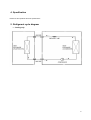
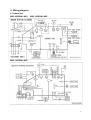
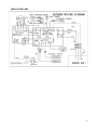
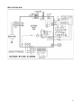
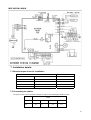
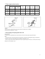
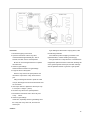
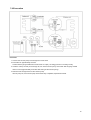
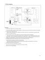
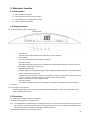
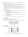
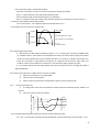
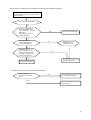
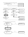
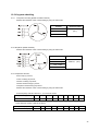
SERVICE MANUAL AIR-CON SILVER SERIES DC INVERTER SPLIT WALL-MOUNTED AC A17EM4C4M09 / A17CI4C4M09 A18EM4C4M12 / A18CI4C4M12 A17EM4C4M18 / A17CI4C4M18 A22EM4C4M24 / A22CI4C4M24 V1.0 Oct, 2009 CONTENTS 1. Precaution .................................................................................................................................................... 1 1.1 Safety Precaution ................................................................................................................................................ 1 1.2 Warning ............................................................................................................................................................... 1 2. Function........................................................................................................................................................ 4 3. Dimension .................................................................................................................................................... 6 3.1 Indoor Unit ........................................................................................................................................................... 6 3.2 Outdoor Unit ........................................................................................................................................................ 7 4. Specification ................................................................................................................................................ 8 5. Refrigerant cycle diagram .......................................................................................................................... 8 6. Wiring diagram............................................................................................................................................. 9 6.1 Indoor Unit ............................................................................................................................................................. 9 6.2 Outdoor Unit......................................................................................................................................................... 10 7. Installation details...................................................................................................................................... 13 7.1 Wrench torque sheet for installation .................................................................................................................. 13 7.2 Connecting the cables ....................................................................................................................................... 13 7.3 Pipe length and the elevation ............................................................................................................................ 14 7.4 Air purging of the piping and indoor unit ............................................................................................................ 14 7.5 Pumping down (Re-installation)......................................................................................................................... 16 7.6 Re-air purging (Re-installation).......................................................................................................................... 17 7.7 Balance refrigerant of the 2-way, 3-way valves ................................................................................................. 18 7.8 Evacuation......................................................................................................................................................... 19 7.9 Gas charging ..................................................................................................................................................... 20 8. Operation characteristics ......................................................................................................................... 21 9. Electronic function .................................................................................................................................... 22 9.1 Abbreviation ...................................................................................................................................................... 22 9.2 Display function ................................................................................................................................................. 22 9.3 Protection .......................................................................................................................................................... 22 9.4 Fan-Only Mode.................................................................................................................................................. 23 9.5 Cooling Mode .................................................................................................................................................... 23 9.6 Drying mode ...................................................................................................................................................... 25 9.7 Auto mode function............................................................................................................................................ 25 9.8 Forced operation function.................................................................................................................................. 25 9.9 Two speeds outdoor fan function....................................................................................................................... 25 9.10 Timer function .................................................................................................................................................. 26 9.11 Sleep function mode ........................................................................................................................................ 26 9.12 Auto-Restart function....................................................................................................................................... 26 9.13 Ionizer/Plasma dust collector function(optional) .............................................................................................. 26 10. Troubleshooting....................................................................................................................................... 26 10.1 Indoor Unit Error Display ................................................................................................................................. 27 10.2 Diagnosis and Solution.................................................................................................................................... 28 10.3 Key parts checking. ......................................................................................................................................... 32 1. Precaution 1.1 Safety Precaution installation stand. and property damage, the following instructions It may cause injury, accident, or damage to the product. Be sure the installation area does not must be followed. deteriorate with age. To prevent injury to the user or other people Incorrect operation due to ignoring instruction will cause harm or damage. Before service unit, be sure to read this service manual at first. If the base collapses, the air conditioner could fall with it, causing property damage, product failure, and personal injury. Do not let the air conditioner run for a long time when the humidity is very high and a door or a window is left open. 1.2 Warning Installation Do not use a defective or underrated circuit breaker. Use this appliance on a dedicated Moisture may condense and wet or damage furniture. Take care to ensure that power cable could not be pulled out or damaged during operation. circuit. There is risk of fire or electric shock. Do not place anything on the power cable. There is risk of fire or electric shock. For electrical work, contact the dealer, seller, There is risk of fire or electric shock. Do not plug or unplug the power supply a qualified electrician, or an Authorized service plug during operation. center. There is risk of fire or electric shock. Do not touch (operation) the product with Do not disassemble or repair the product, there is risk of fire or electric shock. Always ground the product. There is risk of fire or electric shock. Install the panel and the cover of control box securely. There is risk of fire of electric shock. Always install a dedicated circuit and breaker. Improper wiring or installation may cause fore or electric shock. Use the correctly rated breaker of fuse. There is risk of fire or electric shock. Do not modify or extend the power cable. There is risk of fire or electric shock. Do not install, remove, or reinstall the unit by yourself(customer). There is risk of fire, electric shock, explosion, or injury. Be caution when unpacking and installing the product. Sharp edges could cause injury, be especially careful of the case edges and the fins on the condenser and evaporator. For installation, always contact the dealer or an Authorized service center. There is risk of fire, electric shock, explosion, or injury. Do not install the product on a defective wet hands. There is risk of fire or electric shock. Do not place a heater or other appliance near the power cable. There is risk of fire and electric shock. Do not allow water to run into electric parts. It may cause fire, failure of the product, or electric shock. Do not store or use flammable gas or combustible near the product. There is risk of fire or failure of product. Do not use the product in a tightly closed space for a long time. Oxygen deficiency could occur. When flammable gas leaks, turn off the gas and open a window for ventilation before turn the product on. Do not use the telephone or turn switches on or off. There is risk of explosion or fire. If strange sounds, or small or smoke comes from product. Turn the breaker off or disconnect the power supply cable. There is risk of electric shock or fire. Stop operation and close the window in storm or hurricane. If possible, remove the product from the window before the hurricane 1 arrives. There is risk of property damage, failure of product, or electric shock. Do not open the inlet grill of the product It may cause corrosion on the product. Corrosion, particularly on the condenser and evaporator fins, could cause product malfunction or inefficient operation. during operation. (Do not touch the electrostatic filter, if the unit is so equipped.) Operational There is risk of physical injury, electric shock, or product failure. When the product is soaked (flooded or Do not expose the skin directly to cool air submerged), contact an Authorized service center. There is risk of fire or electric shock. Be caution that water could not enter the product. There is risk of fire, electric shock, or product damage. Ventilate the product from time to time when operating it together with a stove, etc. There is risk of fire or electric shock. Turn the main power off when cleaning or maintaining the product. There is risk of electric shock. When the product is not be used for a long time, disconnect the power supply plug or turn off the breaker. There is risk of product damage or failure, or unintended operation. Take care to ensure that nobody could step on or fall onto the outdoor unit. This could result in personal injury and product damage. CAUTION Always check for gas (refrigerant) leakage after installation or repair of product. Low refrigerant levels may cause failure of product. Install the drain hose to ensure that water is drained away properly. A bad connection may cause water leakage. Keep level even when installing the product. To avoid vibration of water leakage. Do not install the product where the noise or hot air from the outdoor unit could damage the neighborhoods. It may cause a problem for your neighbors. Use two or more people to lift and transport the product. Avoid personal injury. Do not install the product where it will be exposed to sea wind (salt spray) directly. for long periods of time. (Do not sit in the draft). This could harm to your health. Do not use the product for special purposes, such as preserving foods, works of art, etc. It is a consumer air conditioner, not a precision refrigerant system. There is risk of damage or loss of property. Do not block the inlet or outlet of air flow. It may cause product failure. Use a soft cloth to clean. Do not use harsh detergents, solvents, etc. There is risk of fire, electric shock, or damage to the plastic parts of the product. Do not touch the metal parts of the product when removing the air filter. They are very sharp. There is risk of personal injury. Do not step on pr put anything on the product. (outdoor units) There is risk of personal injury and failure of product. Always insert the filter securely. Clean the filter every two weeks or more often if necessary. A dirty filter reduces the efficiency of the air conditioner and could cause product malfunction or damage. Do not insert hands or other object through air inlet or outlet while the product is operated. There are sharp and moving parts that could cause personal injury. Do not drink the water drained from the product. It is not sanitary could cause serious health issues. Use a firm stool or ladder when cleaning or maintaining the product. Be careful and avoid personal injury. Replace the all batteries in the remote control with new ones of the same type. Do not mix old and mew batteries or different types of batteries. There is risk of fire or explosion. Do not recharge or disassemble the batteries. Do not dispose of batteries in a fire. They may burn of explode. If the liquid from the batteries gets onto 2 your skin or clothes, wash it well with clean water. Do not use the remote of the batteries The chemical in batteries could cause burns or other health hazards have leaked. 3 2. Function Indoor unit Operation by remote controller Sensing by room temperature Room temperature sensor. Pipe temperature sensor. Room temperature control Maintain the room temperature in accordance with the setting temperature. Anti-freezing control in cooling Prevent the water being frozen on evaporator by sensing the evaporator pipe temperature in cooling mode Ionizer (Optional) Time Delay Safety control Restarting is for approx. 3 minutes.. Indoor fan speed control Plasma (Optional) Turbo wind, high, med, low, breeze. Two-direction air vane Easy clean panel The unit will decide the louver direction according to operation mode. Sleep mode auto control The fan is turn to low speed (cooling/heating). The unit will be turn off at the seventh hour. Self-diag. function Tele Remote control Tele Remote control (Optional) Independent dehumidification The function is usually used in rainy days in springtime or damp areas. Air flow Direction control The louver can be set at the desired position or swing up and down automatically Auto mode The mode can be change by the room temperature. Temp. Compensation Auto-restart function When the power supply is interrupted and then restore, the air conditioners automatically restore the previous function setting. Flexible wiring connection 4 Outdoor unit Power relay control The unit has 3 mins delay between continuously ON/OFF operations. Low ambient kit The unit can operate in cooling mode at low ambient temperature conditions. Low noise air flow system Bird tail propeller fan makes the outdoor unit run more quietly. Hydrophilic aluminum fin The hydrophilic fin can improve the heating efficiency at operation mode. Discharge pipe temperature protect Anti-rust cabinet Made from electrolytic zinc steel sheet and anti-rust coated components. Valve protection cover It protects the valves and prevents water from dripping. 5 3. Dimension 3.1 Indoor Unit Dimension W H D MSC-09CRDN1-NR0 710 250 195 MSC-12CRDN1-NR0 790 265 195 MSC-18CRDN1-NQ0 920 292 225 MSC-24CRDN1-NQ0W 1080 330 228 Mode 6 3.2 Outdoor Unit Dimension W H D L1 L2 L3 Mode 030 700 535 235 458 250 535 110 780 540 250 549 250 540 150 760 590 285 530 315 590 210 845 695 335 560 335 695 7 4. Specification Please see the special file about the specifications. 5. Refrigerant cycle diagram Cooling only 8 6. Wiring diagram 6.1 Indoor Unit MSC-09CRDN1-NR0 MSC-12CRDN1-NR0 MSC-18CRDN1-NQ0 9 MSC-24CRDN1-NQ0W 6.2 Outdoor Unit MOA-09CDN1-NR0 10 MOB-12CDN1-NR0 11 MOC-18CDN1-NQ0 12 MOF-24CDN1-NQ0W 7. Installation details 7.1 Wrench torque sheet for installation Outside diameter Torque mm inch Kgf.m Ф6.35 1/4 1.8 Ф9.53 3/8 4.2 Ф12.7 1/2 5.5 Ф15.9 5/8 6.6 7.2 Connecting the cables The power cord of connect should be selected according to the following specifications sheet. Grade Unit 9K 12K 18K 24K mm2 1.5 1.5 2.5 2.5 13 7.3 Pipe length and the elevation Standard Pipe size Capacity Btu/h Gas Liquid 9k 3/8’’ (Ф9.53) 1/4’’ (Ф6.35) length (m) 5 Max. Max. Additional Elevation Length refrigerant B (m) A (m) (g/m) 20 30 8 12k 1/2’’ (Ф12.7) 1/4’’ (Ф6.35) 5 8 20 30 18k 1/2’’ (Ф12.7) 1/4’’ (Ф6.35) 5 10 25 30 24k 5/8’’ (φ15.9) 3/8’’ (φ9.53) 5 10 25 65 Caution: Capacity is base on standard length and maximum allowance length is base of reliability. Oil trap should be installed per 5-7 meters. 7.4 Air purging of the piping and indoor unit Required tools: Hexagonal wrench; adjustable wrench; torque wrenches, wrench to hold the joints and gas leak detector. Note: The air in the indoor unit and in the piping must be purged. If air remains in the refrigeration piping, it will affect the compressor, reduce the cooling capacity, and could lead to a malfunction of unit. Be sure, using a torque wrench to tighten the service port cap (after using the service port), so that it prevents the gas leakage from the refrigeration cycle. 14 If gas leakage is discovered in step (3) above, take Procedure 1. Recheck the piping connections. 2. Open the valve stem of the 2-way valve counterclockwise approximately 90’, wait 10 seconds, and then set it to closed position. Be sure to use a hexagonal wrench to operate the valve stem. 3. Check for gas leakage. the following measures. If the leaks stop when the piping connections are tightened further, continue working from step (4). If the gas leaks do not stop when the connections are retightened, repair the location of the leak, discharge all of the gas through the service port, and then recharge with the specified amount of gas from a gas cylinder. Check the flare connection for gas leakage 4. Purge the air from the system. Set the 2-way valve to the open position and remove the cap from the 3-way valve’s service port. Using the hexagonal wrench to press the valve core pin, discharge for three seconds and then wait for one minute. 5. Use torque wrench to tighten the service port cap to a torque of 1.8 kgf.m. (18n.m) 6. Set the 3-way valve to the opened position. 7. Mounted the valve stem nuts to the 2-way and 3-way valves. 8. Check for gas leakage. At this time, especially check for gas leakage from the 2-way and 3-way stem nuts, and from the service port. Caution: 15 7.5 Pumping down (Re-installation) Procedure 1. Confirm that both the 2-way and 3-way valves are set to the opened position. Remove the valve stem caps and confirm that the valve stems are in the opened position. Be sure to use a hexagonal wrench to operate the valve stems. 2. Operate the unit for 10 to 15 minutes. 3. Stop operation and wait for 3 minutes, then connect the charge set to the service port of the 3-way valve. Connect the charge hose with the push pin to the gas service port. 5. Air purging of the charge hose. Open the low-pressure valve on the charge set slightly to purge air from the charge hose. 6. Set the 2-way valve to the close position. 7. Operate the air conditioner at the cooling cycle and stop it when the gauge indicates 0.1MPa. 8. Immediately set the 3-way valve to the closed position. Do this quickly so that the gauge ends up indicating 0.3 to 0.5Mpa. Disconnect the charge set, and amount the 2-way and 3-way valve’s stem nuts and service port caps. Use a torque wrench to tighten the service port cap to a torque of 1.8 kgf.m. Be sure to check for gas leakage. 16 7.6 Re-air purging (Re-installation) Procedure: 1. Confirm that both the 2-way and 3-way valves are set to the closed position. 2. Connect the charge set and a charging cylinder to the service port of the 3-way valve. Leave the valve on the charging cylinder closed. 3. Air purging. Open the valves on the charging cylinder and the charge set. Purge the air by loosening the flare nut on the 2-way valve approximately 45’ for 3 seconds then closing it for 1 minute; repeat 3 times. After purging the air, use a torque wrench to tighten the flare nut to on the 2-way valve. 4. Check the gas leakage. Check the flare connections for gas leakage. 5. Discharge the refrigerant. Close the valve on the charging cylinder and discharge the refrigerant until the gauge indicates 0.3 to 0.5 Mpa. 6. Disconnect the charge set and the charging cylinder, and set the 2-way and 3-way valves to the open position. Be sure to use a hexagonal wrench to operate the valve stems. 7. Mount the valve stems nuts and the service port cap. Be sure to use a torque wrench to tighten the service port cap to a torque 18N.m. Be sure to check the gas leakage. 17 7.7 Balance refrigerant of the 2-way, 3-way valves Procedure: 1. Confirm that both the 2-way and 3-way valves are set to the open position. 2. Connect the charge set to the 3-way valve’s service port. Leave the valve on the charge set closed. Connect the charge hose with the push pin to the service port. 3. Open the valves (Low side) on the charge set and discharge the refrigerant until the gauge indicates 0.05 to 0.1Mpa. If there is no air in the refrigeration cycle [the pressure when the air conditioner is not running is higher than 0.1Mpa, discharge the refrigerant until the gauge indicates 0.05 to 0.1 Mpa. If this is the case, it will not be necessary to apply an evacuation. Discharge the refrigeration gradually; if it is discharged too suddenly, the refrigeration oil sill be discharged. 18 7.8 Evacuation Procedure: 1. Connect the vacuum pump to the charge set’s centre hose. 2. Evacuation for approximately one hour. Confirm that the gauge needle has moved toward -0.1 Mpa (-76 cmHg) [vacuum of 4 mmHg or less]. 3. Close the valve (Low side) on the charge set, turn off the vacuum pump, and confirm that the gauge needle does not move (approximately 5 minutes after turning off the vacuum pump). 4. Disconnect the charge hose from the vacuum pump. Vacuum pump oil, if the vacuum pump oil becomes dirty or depleted, replenish as needle. 19 7.9 Gas charging Procedure: 1. Connect the charge hose to the charging cylinder. Connect the charge hose which you disconnected from the vacuum pump to the valve at the bottom of the cylinder. 2. Purge the air from the charge hose. Open the valve at the bottom of the cylinder and press the check valve on the charge set to purge the air (be careful of the liquid refrigerant). 3. Open the valves (Low side) on the charge set and charge the system with liquid refrigerant. If the system cannot be charge with the specified amount of refrigerant, if can be charged with a little at a time (approximately 150g each time0 while operating the air conditioner in the cooling cycle; however, one time is not sufficient, wait approximately 1 minute and then repeat the procedure.(pumping down-pin). 4. Immediately disconnect the charge hose from the 3-way valve’s service port. Stopping partway will allow the refrigerant to be discharged. If the system has been charged with liquid refrigerant while operating the air conditioner, turn off the air conditioner before disconnecting the hose. 5. Mounted the valve stem caps and the service port Use torque wrench to tighten the service port cap to a torque of 18N.m. Be sure to check for gas leakage. 20 8. Operation characteristics Mode Temperature Room temperature Outdoor temperature Cooling operation Drying operation 17℃~ 32℃ 10℃~ 32℃ 18℃~50℃ (-15℃~43℃:For the models with low temperature cooling system) 10℃~ 50℃ CAUTION: 1. If air conditioner is used outside of the above conditions, certain safety protection features may come into operation and cause the unit to function abnormally. 2. Room relative humidity less than 80%. If the air conditioner operates in excess of this figure, the surface of the air conditioner may attract condensation. Please sets the vertical air flow louver to its maximum angle (vertically to the floor), and set HIGH fan mode. 3. Optimum performance will be achieved within this operating temperature. 21 9. Electronic function 9.1 Abbreviation T1: Indoor ambient temperature T2: Pipe temperature of indoor heat exchanger T3: Pipe temperature of outdoor heat exchanger T4: Outdoor ambient temperature 9.2 Display function 9.2.1 Icon explanation on indoor display board. ① Auto indicator This indicator illuminates when the air conditioner is in AUTO operation. ② Timer indicator This indicator illuminates when TIMER is set ON/OFF. ③ PRE.-DEF. Indicator This indicator illuminates when the air conditioner starts defrosting automatically or when the warm air control feature is activated in heating mode. ④ TEMPERATURE indicator Usually it displays the temperature settings. When change the setting temperature, this indicator begins to flash, and stops 20 seconds later. It displays the room temperature when the air conditioner is in FAN only operation, and the range of that is 0~50℃. When the unit stops operation, it returns to original factory settings. Displays the malfunction code or protection code. ⑤ Frequency indicator This indicator appears only when the compressor is in operation and indicates the current operating frequency. 9.2.2 LED display control function. Pressing “LED display” button on remote controller will turn off all displays on indoor unit, while pressing once again, all displays will resume. 9.3 Protection 9.3.1 Three Minutes Delay at restart for compressor. 9.3.2 Temperature protection of compressor top. 9.3.3 If the temperature of compressor top is too high(higher than 115℃ and the Over-load Protector is cut, the units stop. When the Over-load Protector restore and close(lower than 100℃), the compressor will restart( in this case the compressor is restricted by Three Minutes Delay protection. 9.3.4 Temperature protection of compressor exhaust. 22 If the exhaust temp. of compressor is higher than 115℃ and lasts for 5 seconds, the compressor stops and does not resume until the exhaust temp. is lower than 90℃. 9.3.5 Inverter module Protection, Inverter module Protection itself has a protection function against current, voltage and temperature. If these protections happened, the corresponding code will display on indoor unit LED. 9.3.6 Sensor protection at open circuit and breaking disconnection 9.3.7 Fan Speed is out of control. When Indoor Fan Speed is too low (lower than 300RPM for 50 seconds), the unit stops and LED displays failure information and can’t return to normal operation automatically. 9.3.8 Cross Zero signal error warning. If there are 20 alternations of Cross Zero signals are incorrect, the unit stops and LED displays failure information. After resuming, the motor rotates again. The spacing of Cross Zero signal is 6-13ms. 9.3.9 Indoor fan delayed open function 9.3.10 For all modes, when the units are turned on, the indoor fan can operate 10 seconds after the action of louver. 9.3.11 Compressor preheating functions. 1) Preheating permitting condition: If T4(outdoor ambient temperature)<3℃ and the machine connects to power supply newly or if T4<3℃ and compressor has stopped for over 3 hours, the compressor heating cable will work. 2) Preheating mode: A weak current flows through the coil of compressor from the wiring terminal of compressor, then the compressor is heated without operation. 3) Preheating release condition: If T4>5℃ or user turns on the machine and compressor runs, preheating function will stop. 9.4 Fan-Only Mode 9.4.1 Temperature setting function is disabled, and no setting temperature display. 9.4.2 In this mode, the action of louver is the same as in cooling mode. 9.4.3 The action of auto fan in fan-only mode is the same as auto fan in cooling mode with 24℃ setting temperature. ℃ high T1 – 24 3.5 3.0 medium 1.5 1.0 low 9.5 Cooling Mode ΔT=(room temp) – (setting Temp) 9.5.1 The operation frequency of compressor after starting submits to following rule. 3.5 3.0 A B -0.5 -1.0 H When the machine is running and ΔT(=room temp. – setting temp.) changes, the frequency of compressor will 23 rise or descend a grade (7 minutes after starting). After start, if ΔT stays in a zone for 3 minutes, the frequency will change as follow: Zone A : Current frequency rise a grade till the maximum grade. Zone B: Elevate or keep or descend the frequency of compressor. Zone H: Compressor stops after running as the minimum frequency for 60 minutes or ΔT is less than -2℃. 9.5.2 Indoor heat exchanger anti-freezing function. If T2 is lower than 0℃, the compressor stops and resumes when T2>5℃. 9.5.3 Outdoor unit current control in cooling mode. comp. pause outdoor unit current I3COOL freq. descends if curr. rises; I2COOL freq. remains if curr. descends I1COOL running normally 9.5.4 Rating capacity test function 1) Set the indoor unit with remote controller as: high fan, 17℃ in cooling mode, then press “TURBO” button on controller 6 times or more within 10 seconds(make sure indoor unit receives these signals), the machine will turn into rating capacity test mode, the buzzer will make a “di” sound for 2 seconds continuously. Also, indoor fan will change to rating speed, the frequency of compressor will be fixed as rating value. Any condition of above is not satisfied, the machine can not be turned into rating capacity test mode. 2) The machine will quit from the rating capacity test mode if running for 5 hours or changing fan speed or setting temperature. 9.5.5 Turbo function (press the “TURBO” button on remote controller) 9.5.6 1) Elevate current frequency to a higher grade. 2) Indoor fan turns to turbo speed. 3) After running for 30 minutes the machine will turn back to previous setting mode. Indoor fan operation rule. 1) In cooling mode, indoor fan runs all the time and the speed can be selected as high, medium, low and auto. Auto fan in cooling mode acts as follow: ΔT=(room temp) – (setting Temp) 2) ℃ high 4.0 3.0 medium 1.5 1.0 low 9.5.7 Condenser high temperature protection function(in cooling and drying mode) If T3>60℃ for 5 seconds, compressor will stop immediately, and the machine will not resume until T3<52℃. 24 9.6 Drying mode 9.6.1 Indoor fan speed is fixed at breeze grade and can’t be changed. The horizontal angle is the same as in cooling mode. 9.6.2 Room overlow temperature protection In drying mode, if room temperature is lower than 10℃, compressor will stop and not resume until room temperature climbs up to 12℃. 9.6.3 Evaporator anti-freezing protection, condenser high temperature protection and outdoor unit frequency limit are valid, and they are the same as that in cooling mode. 9.6.4 Horizontal louver action is the same as that in cooling mode. 9.7 Auto mode function 9.7.1 This mode can be chosen with remote controller and the setting temperature can be changed between 17~30℃. In auto mode, the machine will choose cooling or fan-only mode according to ΔT(ΔT =T1-Ts). ΔT=T1-Ts Running mode ΔT>1℃ Cooling ΔT≤1℃ Fan-only 9.7.2 Indoor fan will choose auto speed of relevant mode. 9.7.3 If the machine switches mode between heating and cooling, compressor will keep stopping for 15 minutes and then rechoose mode according to ΔT. 9.7.4 If the setting temperature is modified, the machine will rechoose running function. 9.8 Forced operation function 9.8.1 Forced cooling and auto function can carry out with a touch button. In these two modes, the machine can be changed by remote controller to any other mode at any moment. 9.8.2 When the machine is off, pressing the touch button will carry the machine to forced auto mode, after this, if pressing the button once again within 5 seconds, the machine will turn into forced cooling mode. In forced auto, forced cooling or any other operation mode, pressing touch button will turn off the machine. In forced operaton, remote control is available. 9.8.3 In forced operation mode, all general protections is available. 9.8.4 In forced cooling mode, after running for 30 minutes. the machine will turn to normal auto mode which setting temperature is 24℃. 9.8.5 The action of forced auto mode is the same as normal auto mode which temperature is 24℃. 9.9 Two speeds outdoor fan function ℃ 22 high 20 low outdoor fan speed outdoor temperature 9.9.1 Outdoor fan action in cooling & drying mode(including cooling in auto & forced mode). Outdoor fan action in cooling & drying mode (including cooling in auto & forced mode). 25 9.10 Timer function 9.10.1 Timing range is 24 hours, and the minimum resolution is 15 minutes. 9.10.2 Timer on. After turning off, the machine will turn on automatically when reaching the setting time. 9.10.3 Timer off. After turning on, the machine will turn off automatically when reaching the setting time. 9.10.4 Timer on/off. After turning off, the machine will turn on automatically when reaching the setting “on” time, and then turn off automatically when reaching the setting “off” time. 9.10.5 Timer off/on. After turning on, the machine will turn off automatically when reaching the setting “off” time, and then turn on automatically when reaching the setting “on” time. 9.10.6 The tolerance of timer is 1 minute per hour. 9.11 Sleep function mode 9.11.1 Operation time in sleep mode is 7 hours. After 7 hours the machine quits this mode and turns off. 9.11.2 In cooling or auto mode sleep function is available. 9.11.3 Operation process in sleep mode is as follow: 1) After pressing ECONOMIC or SLEEP button on controller, the machine will turn into sleep mode. 2) When cooling, the setting temperature rises 1℃(be lower than 30℃) every one hour, 2 hour later the rising stops and indoor fan is fixed as low speed. 9.11.4 If user uses timer on function in sleep mode, sleep function will pause and not resume until reaches the setting on time. 9.11.5 When user uses timer off function in sleep mode(or sleep function in timer off mode), if the timing time is less than 7 hours, sleep function will be cancelled when reaching the setting time. If the timing time is more than 7 hours, the machine will not stop until reaches the setting off time in sleep mode. 9.12 Auto-Restart function The indoor unit is equipped with auto-restart function, which is carried out through an auto-restart module. In case of a sudden power failure, the module restores the setting conditions before the power failure. The unit will resume the previous operation setting (not including Swing function) automatically after 3 minutes when power returns. 9.13 Ionizer/Plasma dust collector function(optional) The indoor unit is equipped with Ionizer, which is controlled by the CLEAN AIR button on the remote controller when the unit is turned on. Press the CLEAN AIR button to activate the function. Press it again to stop the function. During the time when Ionizer being controlled by remote controller, Ionizer will be turned off automatically, if indoor fan stops running due to malfunctions or anti-cold-wind. When indoor fan restarts after malfunctions being eliminated and anti-cold-wind being released, Ionizer will be available again. 10. Troubleshooting Safety Because of there are capacitors in PCB and relative circuit in outdoor unit, even shut down the power supply, electricity power still are kept in capacitors, do not forget to discharge the electricity power in capacitor. 26 Electrolytic Capacitors (HIGH VOLTAGE! CAUTION!) Bulb (25-40W) 10.1 Indoor Unit Error Display Display LED STATUS E0 EEPROM parameter error E1 Indoor / outdoor units communication protection E2 Zero-crossing signal error E3 Indoor fan speed out of control E5 Open or short circuit of outdoor temperature sensor E6 Open or short circuit of room or evaporator temperature sensor E7 Outdoor fan speed out of control P0 IGBT over-strong current protection P1 Over voltage or too low voltage protection P2 Temperature protection of compressor top. P4 Inverter compressor drive error 27 Note: E4 & P3: Reserved function 10.2 Diagnosis and Solution 10.2.1 E0(EEPROM parameter error) error diagnosis and solution Circuit or software error on indoor PCB Replace indoor PCB 28 102.2 E1(indoor / outdoor units communication protection) error diagnosis and solution Disconnect the power supply, after 1 minute, connect the power supply , turn on the unit with remote controller Does the unit work normally? NO Check the wiring between indoor and outdoor unit. Is the connection of L, N, S and GND good? Is the GND connection on outdoor PCB good? NO Reconnect and retest again Yes Is the LED4(red) on outdoor PCB bright and LED1(yellow) blinking? Replace indoor PCB and repower on. Is the failure cleared? Yes No The power supply for outdoor PCB is fail. Check the wiring on outdoor PCB comparing with wiring plate. Is the connection good? Yes No Replace outdoor e-box. Correct the connection. 10.2.3 E2(zero-crossing signal error) diagnosis and solution Is power supply and connection of connectors good? NO Be sure the power supply is good and correct the connection YES Indoor PCB is defective. Replace the indoor PCB. 29 10.2.4 E3(indoor fan speed out of control) diagnosis and solution Is the indoor fan motor connector and connection good? NO Repair the connector and reconnect YES Indoor PCB is defective. Replace the indoor PCB. YES Is voltage being applied to the fan motor right? NO Replace the indoor fan motor 10.2.5 E5(Open or short circuit of outdoor temperature sensor) diagnosis and solution. Is the outdoor temperature sensor connector and connection good? NO Repair the connector and reconnect YES Replace the sensor and check if E5 display again? YES Replace outdoor e-box 10.2.6 E6(open or short circuit of room or evaporator temperature sensor) diagnosis and solution. Is the indoor temperature and evaporator sensor connector and connection good? NO Repair the connector and reconnect YES Replace the sensor and check if E6 display again? YES Replace the.indoor PCB 10.2.7 P0(IGBT over-strong current protection) diagnosis and solution. Is all connections on PCB and between PCB and compressor good? NO Repair or correct the connector or connection. YES Replace the outdoor PCB and then repower on. Is the failure cleared? NO Check the compressor 30 10.2.8 P1(over voltage or too low voltage protection) diagnosis and solution. Is the power supply good? NO Be sure the power supply is normal when using the units YES Replace the outdoor e-box. 10.2.9 P2(temperature protection of compressor top) diagnosis and solution. NO Does compressor operate? YES Is the connection good? NO Reconnect and retest. YES Is refrigerant circulation volume normal? NO Is protector normal? Replace the protector. YES NO Check the outdoor main PCB. Is there some problem? Charge refrigerant YES Replace the outdoor PCB. Is abnormality the same after gas charging? NO Check refrigerant system (such as clogging of capillary, 10.2.10 P4(inverter compressor drive error) diagnosis and solution. Is the connection of compressor good? Is the wiring se uence right? The voltage range proper? NO Reconnect and retry YES Replace the outdoor E-box. If the problem comes to again, check coil resistance of inverter compressor, is it 0.71ohm? NO Replace inverter compressor 31 10.3 Key parts checking. 10.3.1. Compressor checking (Model: DA108X1C-20FZ3). Measure the resistance value of each winding by using the multi-meter. Position Resistance Value Blue - Red 0.71Ω Blue - Black (20℃) Red - Blue 10.3.2 Step Motor (Model: MP2835). Measure the resistance value of each winding by using the multi-meter. Position Resistance Value Blue - Red Pink - Orange 200Ω±7% (25℃) Pink - Yellow Yellow - Red 10.3.3 Temperature Sensors. Room temp.(T1) sensor, Indoor coil temp.(T2) sensor, Outdoor coil temp.(T3) sensor, Outdoor ambient temp.(T4) sensor, Compressor exhaust temp.(Te) sensor. Measure the resistance value of each winding by using the multi-meter. Some frequently-used R-T data for T1, T2, T3 and T4 sensor: Temperature (℃) 5 10 15 20 25 30 40 50 60 Resistance Value (KΩ) 26.9 20.7 16.1 12.6 10 8 5.2 3.5 2.4 Some frequently-used R-T data for Te sensor: Temperature (℃) 5 15 25 35 60 70 80 90 100 Resistance Value (KΩ) 141.6 88 56.1 36.6 13.8 9.7 6.9 5 3.7 32 KΩ ℃ 33


![ナンバー117 11月1日発送 [PDFファイル/330KB]](http://vs1.manualzilla.com/store/data/006539745_2-e2df90708e57a1d058a404b059037b4c-150x150.png)