1
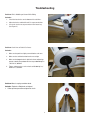
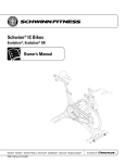
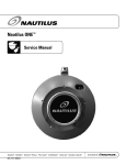
Schwinn A.C.™ Classic, Schwinn A.C.™ Sport,
and Schwinn A.C.™ Performance
Nautilus®
003-3331-051409A
Bowflex®
Schwinn® Fitness
StairMaster®
Universal®
Nautilus Institute®
© 2009 Nautilus, Inc., All rights reserved
™ and ® indicate a trademark or registered trademark. Nautilus, Inc. trademarks include NAUTILUS®, BOWFLEX®, STAIRMASTER®, SCHWINN® and UNIVERSAL® and respective logos.
1-800-NAUTILUS www.nautilus.com.. Other trademarks are the property of their respective owners.
Table of Contents
Important Safety Warnings..........................................................................................................................................................................3
Tools.................................................................................................................................................................................................................4
Serial Number.................................................................................................................................................................................................5
Troubleshooting.............................................................................................................................................................................................5
Console...........................................................................................................................................................................................10
Power Sensor................................................................................................................................................................................12
Speed Sensor.................................................................................................................................................................................13
Parts...............................................................................................................................................................................................................14
Contacts.........................................................................................................................................................................................................17
2
Important Safety Warnings
This icon means a potentially hazardous situation which, if not avoided, could result in death or serious injury. Failure to
follow these precautions can cause damage to the Schwinn® IC Bike series, serious injury to users and bystanders, and can
also compromise the effectiveness of your exercise program.
Before using this equipment, obey the following warnings:
Read and understand the Service Manual before working on the machine.
Failure to obey the instructions and safety warnings could cause injury to the service technician or bystanders.
1.
Damaged machines or machines under repair must be marked as “Out of Service”, set aside and prevented from being
used by customers.
2.
Keep bystanders and children away from the product being serviced at all times.
3.
Make sure that the repair is done in an appropriate work space away from foot traffic and exposure to bystanders.
4.
The adjustments and repairs to Nautilus equipment must only be done by a professional service technician trained to
service Nautilus equipment.
5.
Some components of the equipment can be heavy or awkward. Enlist the service of a second person when you do maintenance steps involving these components. Do not try to do heavy or awkward steps on your own.
6.
Use only genuine Nautilus replacement parts and hardware. Failure to use genuine replacement parts can adversely effect the safety and functionality of the equipment creating a risk to users.
7.
Be sure that all warning stickers and instructional placards applied to the product stay present and in good condition
when doing maintenance or replacing components. If necessary request replacement warning stickers or placards from
3
Tools
We recommend the following tools and lubes to properly assemble, maintain and repair all Schwinn® Indoor Cycling bikes.
Tools
Lubricants
1.
Torque wrench w/ 8mm Hex key socket: used to tighten the
crank bolts of crank arms to the specified torque.
Note: To obtain the recommended lubricates contact Nautilus
Inc. at 1-800-NAUTILUS.
2.
Pedal wrench: Has 15mm and 9/16” wrench to tighten and loosen
pedals. 6mm hex key can be used on pedals with cage and toe
strap that come on the classic bike, but not on the pedals with spd
clips.
1.
Schwinn® Fit-Tech Silicone Spray: recommended for all
moving parts (e.g., handle bar post, seat post & slide, poppins, resistance knob etc.)
2.
3.
ISIS Crank puller: needed to take off right and left crank arms.
Schwinn® Equipment Polish: recommended on a damp cloth
when wiping down the frame after use.
4.
Bottom Bracket tool for removal and installation of ISIS BB. ISIS BB 3.
should be tightened to 600-700 kgf*cm / 44-51 lbs*ft / 60-69Nm on
both right and left sides.
Schwinn® Citrus Chain Wax: recommend to lubricate
the chain through the rear hole in the chain guard as the
flywheel is rotating.
5.
Adjustable wrench: used to tighten or loosen the pop pin
assembly from frame.
6.
17mm wrench: used to adjust the inside axle nuts closest to the
flywheel bearings.
7.
15mm wrench: used to loosen the outside axle nut on each side
of the flywheel bearings.
8.
14mm wrench: used to tighten the nuts of the seat bracket.
9.
5mm hex key and 13mm wrench used to tighten bolts on
stabilizer.
4.
10. The pivot bolt for the brake will use an 8mm hex wrench and a
17mm wrench.
11. 2.5 mm Hex key: used to adjust chain tensioner bolts during
chain tightening, transport wheel nut and bolt and front nut of
the resistance assembly when centering brake pads.
12. 13mm wrench for resistance knob nylon nut.
13. 3mm Hex key: used for the screws of the water bottle cages.
14. Smart Release™ adjusting tool: high quality tool specifically
designed for use with the new adjustable Smart Release™
mechanism. (SR Models only).
15. 3mm Hex key: Install and remove the Console bracket and/
or Speed Sensor. Also attach the console bracket to the
handlebars. #2 philips screwdriver is required to remove
Console battery cover install/remove the console to the
bracket and power sensor to the brake mechanism.
16. 2.5mm Hex key to install/service the Power Sensor.
17. 4mm Hex key: All plastic hardware.
4
Schwinn® Quick Shot: recommended for the threads of
stabilizer bolts and pedals before tightening to crank arms.
Serial Number
Serial Number
Find the serial number on the underside of the machine base. Decode the information in the serial number with the below instructions:
XXXXXX - SKU
VVV - NLS Vendor Code
WKYY - Week/Year
9999 - Machine that made production run
Troubleshooting
Problem: Chain is too loose, tight, or making a grinding sound.
Solution:
1. Use a 15mm wrench or socket to loosen flywheel nuts (A) and
tensioning screws so that when you grab a pedal and try and
move it back and forth, you can feel play in the chain.
2. Use a 3mm Hex wrench to gradually tighten the drive side tensioning screw (B) until you cannot feel any free play.
3. Check for free play with the crank in the 12, 3, 6, and 9 o’clock
positions in case there is a loose or tight spot and make sure
there is no play.
4. Add an additional 1/2 turn on the drive side tensioning screw.
This should help keep the chain tensioned as it is new and
breaks in.
5. Tighten the non-drive side tensioning screw to align and center
the flywheel in the brake assembly.
6. Tighten both flywheel nuts.
A
NOTE: Make sure that the flywheel aligns with the frame.
B
5
Troubleshooting
Problem: Smart Release engages/disengages when pedaling
Solution: Adjust Smart Release
Attention: Only a mechanic trained to work on Schwinn® IC
bicycles should do this procedure. Make adjustments
to the Smart Release™ mechanism only to restore
the mechanism to factory specifications. Never
overtighten.
1.
Begin by riding the bike. This forces the the Smart Release™
mechanism to break free. Pedal up to a moderate speed with
little or no resistance on the flywheel while applying enough
back pressure to the cranks to release the mechanism. Repeat
this several times to ensure that the mechanism is up to
operating temperature and to feel the initial setting.
2.
From the front of the bike, insert the Smart Release™ adjusting
tool into the space between the chain guard and the flywheel.
3.
Rotate the flywheel until the 7mm diameter hole in the Smart
Release™ adjusting plate is visible from the front of the bike.
4.
Tighten the resistance mechanism to prevent the flywheel
from rotating.
5.
Place a 50 lb. dumbell or weight on the right side pedal (chain
guard side) with the crank in the 9 o’clock position.
Note: When properly adjusted, the Smart Release™
mechanism should break free allowing the crank arm
to rotate down under this amount of weight.
6.
Insert the Smart Release™ Adjusting Tool so that the bend in
the tool corresponds to the shape of the flywheel.
7.
Insert the pin of the tool into the hole of the Smart Release™
adjusting plate.
8.
Pull the handle of the tool UP toward the top of the flywheel
to increase the release pressure (higher breakaway force)
and DOWN to decrease the release pressure (lower
breakaway force).
9.
Ride the bike to test that the factory specified resistance has
been achieved.
6
Troubleshooting
Problem: Bike is Wobbling or Uneven While Riding
Solution:
1.
Check the foot levelers on the bottom of the stabilizers.
2.
Adjust the levelers and the bike until it is square on the floor.
3.
Secure the leveler nuts to prevent them from loosening.
(See Figure 5.)
Problem: Crank Arms or Pedals Feel Loose
Solution:
1.
Make sure the pedals are tightly screwed into the crank arms.
2.
Make sure the crank bolts on both crank arms are tight.
3.
Make sure the bottom bracket is tight in the frame and bearings
operate smoothly. Torque bottom bracket cups to 600-700 kgf*cm
/ 44-51 lbs*ft / 60-69Nm.
4.
Tighten and torque the crank arm bolts to 550-600 kgf*cm /
40-44 lbs*ft / 55-60 Nm.
Problem: Metal scraping sound from brake
Solution: Flywheel or Eddy brake misaligned
1.
Follow previous procedure to tighten the chain.
7
Troubleshooting
Problem: Emergency Brake not functioning properly
Solution: Replace full assembly
1.
Loosen the Brake Adjustment Rod (A) clockwise
while loosening the Brake Adjustment Housing (B)
counterclockwise.
2.
As the Brake Adjustment Rod unscrews from the Link Arms (C)
raise the Brake Adjustment Housing and Rod.
3.
Remove the torsion spring and slide out the brake assembly for
replacement.
When reinstalling the Brake Adjustment Rid into the Link
Arms do not overtighten as this will bend the Link Arms.
A
B
C
8
Troubleshooting
Problem: Handlebar or Seat Post is too Tight
Solution:
1.
Clean and lubricate the handlebar/seat post extension tube
and frame sleeves with silicone lube.
2.
If fit remains tight, switch the handlebar or seat post with
one from another bike.
3.
If this does not fix the problem order a new sleeve.
Problem: Stretch Pads - worn out, torn
Solution:
1.
Remove complete pad.
2.
Clean surface of all adhesive material with alcohol or
acetone
3.
Apply replacement pad.
9
Troubleshooting
Console
(Make sure console is updated to the latest firmware version)
Problem: Console does not turn ON.
Solution:
1.
Press any of the three buttons and see if console turns ON.
2.
Change batteries.
3.
Replace Console.
Problem: USB does not work / save data.
Solution:
1.
Check the settings in Service Menu (refer to Owners manual) and make sure USB is enabled.
2.
Change batteries.
3.
Replace Console.
Problem: Cannot start pairing menu when pairing button is pressed.
Solution:
1.
Turn ON the console first by pressing any button. If the console workout timer has not started, press the pairing button to go to
pairing menu (PPP).
2.
Restart the console by taking out the batteries and putting them back in.
3.
Erase EEPROM from Service Menu EP- sub menu.
4.
Replace Console.
Problem: Backlight does not turn ON.
Solution:
1.
Check the backlight option in the Service Menu and make sure it’s not turned OFF.
2.
Replace batteries.
3.
Replace Console.
Problem: Cannot update the firmware . Tried updating the firmware and Console does not turn on or has no display.
Solution:
1.
Replace batteries and retry firmware upgrade.
2.
Use an empty USB stick (1 GB or less), and download the latest firmware version. Firmware version needs to be named as
FB602.hex
3.
Replace the console and try upgrading it.
10
Console (cont.)
Problem: For any error generated in console.
Solution:
1.
Refer to Owners manual for description and solution(s).
2.
If possible, save the Settings in a USB stick by going to Service Mode -> U-- -> U03.
Exporting Console settings to send to Nautilus for troubleshooting help:
s'OTO3ERVICEMODEBY(OLDING!6'%.$34!'%BUTTONFORSECONDS)FWORKOUTHASSTARTEDALREADYSTOPTHE
WORKOUTTURNTHECONSOLEBACKONANDTHENHOLD!6'%.$34!'%BUTTONFORSECONDS
sGo to U-- Menu
sPress backlight
sGo to U03 Menu (Store Data)
sInsert a USB stick
sPress backlight.
sWait a few seconds (backlight will turn OFF once it has finished writing to the USB)
sTake out the USB
sGet out of Service Mode.
sA file “Config.csv” has been saved onto the USB stick
s Send file to: [email protected]
Problem: Console’s display is frozen.
Solution:
1.
Remove the battery to restart console.
2.
If problem persists, replace the console.
Problem: Batteries are being replaced too often.
Solution:
1.
Check the backlight settings, make sure it is not set to ON (ON at all times).
2.
Change backlight settings to stay ON at different rate.
3.
With a DMM check for short on the battery leads on the console.
For all other problems refer to the Owner’s manual.
11
Power Sensor
Problem: Power does not show up on the console (displayed as “---”).
Solution:
1.
Solution 1: The power sensor may be in sleep mode. To wake up the power sensor start pedaling the bike for 10-20s; the
vibrations of the chain and crank movement should be enough to turn on the sensor. If the displayed power still does not show
up tilt the bike over to one side for 5-10s
2.
Solution 2: The power sensor may not be paired with the speed sensor; this will result in transmission of 0 watts at all times
with the console flashing “---” and the power sensor eventually will go back into sleep mode. Follow the pairing procedure
described in the owners manual.
3.
Solution 3: Reset the power sensor by removing and reinstalling the battery.
4.
Solution 4: The battery is dead; replace the battery with a new battery.
5.
Solution 5: The speed sensor may not be detected; in which case the power sensor will go into sleep mode. Ensure that the
speed sensor is functioning correctly.
6.
Solution 6: If the above 5 solutions do not fix the problem, replace the power sensor. Please take note that upon power sensor
replacement the console and speed sensor will need to be re-paired to the new power sensor.
Problem: Displayed power does not increase with brake movement but does change with RPM.
Solution:
1.
The power sensor has more than likely not been full-up calibrated. Follow the full-up calibration procedure in the owner’s manual.
2.
Reset the power sensor by removing and reinstalling the battery.
3.
If the above 2 solutions do not fix the problem, replace the power sensor. Please take note that upon power sensor replacement
the console and speed sensor will need to be re-paired to the new power sensor.
Problem: LEDs do not turn on (or are very dim) when the pairing button is pressed.
Solution:
1.
Reset the power sensor by removing and reinstalling the battery.
2.
The battery is dead; replace the battery with a new battery.
3.
If the above 2 solutions do not fix the problem, replace the power sensor. Please take note that upon power sensor replacement the console and
speed sensor will need to be re-paired to the new power sensor.
12
Troubleshooting
Power Sensor (cont.)
Problem: Displayed power is not accurate.
Solution:
1.
Perform a full-up calibration. Follow the full-up calibration procedure in the owner’s manual.
2.
Perform a 0g calibration. Follow the 0g calibration procedure in the owner’s manual.
3.
If the above 2 solutions do not fix the problem, replace the power sensor. Please take note that upon power sensor replacement the console and
speed sensor will need to be re-paired to the new power sensor.
Problem: Repeated failed pairing with speed sensor.
Solution:
1.
Attempt to pair with a different speed sensor to rule out a bad speed sensor.
2.
If the above solution does not fix the problem, replace the power sensor. Please take note that upon power sensor replacement the console and
speed sensor will need to be re-paired to the new power sensor.
Problem: Rapid power sensor battery drainage.
Solution:
1.
Inspect the rubber gasket between the power sensor and brake carriage for pinch points; exposed battery contacts will cause the battery to
short directly to the brake.
2.
The speed sensor may be stuck in an on state; the power sensor will stay active as long as the speed sensor is active hence reducing battery life
significantly.
3.
If the above 2 solutions do not fix the problem, replace the power sensor. Please take note that upon power sensor replacement the console and
speed sensor will need to be re-paired to the new power sensor.
Speed Sensor
Problem: RPM does not show up on the console.
Solution:
1.
The speed sensor may not be installed correctly. Adjust the sensor such that the flywheel magnet passes <5mm across the speed sensor.
2.
The speed sensor may not be properly paired with the console. Follow the pairing procedure described in the owners manual.
3.
The coin cell battery may be installed backwards. Install the battery in the correct orientation.
4.
The battery is dead; replace the battery with a new battery. Under no circumstances should used batteries be used as a replacement; this will
alter the accuracy of the speed sensor battery monitoring.
5.
If the above 4 solutions do not fix the problem replace the speed sensor. Please take note that upon speed sensor replacement the console and
power sensor (if bike is power enabled) will need to be re-paired to the new speed sensor.
Problem: Speed Sensor will not pair correctly to the Console/Power Sensor
Solution:
1.
The toggle switch may be switched to the cadence setting. Ensure that the toggle switch is in the speed position and re-pair.
2.
The battery is dead; replace the battery with a new battery. Under no circumstances should used batteries be used as a replacement; this will
alter the accuracy of the speed sensor battery monitoring.
3.
If the above 2 solutions do not fix the problem replace the speed sensor. Please take note that upon speed sensor replacement the console and
power sensor (if bike is power enabled) will need to be re-paired to the new speed sensor.
13
Parts
Brake Rod and Knob Replacement
Tools Required:
s
Adjustable wrench
s
3mm hex key for plastic removal
Procedure: Replace the Tension Control Knob
Removal:
1.
Remove one side brake cover.
2.
Turn brake adjustment knob clockwise until brake is fully engaged with the flywheel.
3.
Using an adjustable wrench, unscrew (couter-clockwise) the brake adjustment knob assembly from the frame head tube.
4.
While unscrewing the knob housing from the frame, you will also need to unscrew the brake rod from the brake nut below. The lower portion
of the rod has left hand threads. So while unscrewing the adjustment knob housing from the frame headtube, turn the actual adjustment knob
clockwise until both are un-threaded.
5.
Pull adjustment knob assembly out of frame.
Replacement: Reverse steps of Removal
14
Maintenance
Attention: Any Schwinn® bike that is allowed to operate with torque in excess of the specified values does not qualify for warranty
replacement for the crank arms.
Do NOT torque crank bolts in excess of 480 lbs*ft / 22Nm. Overtightening causees damage to the crank or the bottom bracket
interface.
At the end of each workout:
s
#LEANTHEBIKEWITH3CHWINN® equipment polish and a clean damp cloth.
s
Remove the handlebars from the head tube to allow the handlebar tube and sleeve to dry.
Inspect the Schwinn® Authentic Cycling bike for lose parts, nuts, bolts, etc. Pay special attention to the brake
assembly, seat and handlebar pop-pins. This will prolong the service life of the product.
s
Check the chain for proper adjustment.
s
Lubricate chain.
s
Move the crank arms back and forth. If there is more than 1/4” movement in the chain before the flywheel
turns, tighten the chain (See page 9).
NOTE: Make sure you adjust both sides equally so that the flywheel remains in alignmentwith the frame.
s
#HECKTHECRANKBOLTSWITHATORQUEWRENCH4HETORQUESHOULDNOTEXCEEDIN
LBANDKGF
CM
s
#HECKTHATBOTHPEDALSARESECUREDANDPROPERLYATTACHEDTOTHECRANKARMS
NOTE: Only trained personnel should change the pedals. Unqualified people performing this procedure can
cause threads to cross. Crossed threads do not qualify for warranty replacement.
s
-AKESUREHANDLEBARANDSEATPOPPINSAREFULLYTIGHTENEDANDOPERATINGSMOOTHLY
Use extreme care when servicing the Schwinn® Authentic cycling bike with the chain guard removed. If your fingers or other parts
of the the body come into contact with moving parts inside the bike, amputation or other serious injury may occur. Before starting
any maintenance on the chain drive, familiarlize yourself with all moving parts. Never leave a Schwinn® bike unattended with the
chain guard removed.
NOTICE: Use extreme caution when operating the Eddy brake. High magnatized field can harm credit cards, cell phones, etc.
15
Contacts
EUROPE, MIDDLE EAST & AFRICA
NORTH AMERICA
CUSTOMER SERVICE
Tel: (800) 605-3369
E-mail: [email protected]
INTERNATIONAL CUSTOMER SERVICE
Nautilus International GmbH
Albin-Köbis-Str. 4
51147 Köln
4EL
&AX
E-mail: [email protected]
CORPORATE HEADQUARTERS
Nautilus, Inc.
World Headquarters
16400 SE Nautilus Drive
Vancouver, Washington, USA 98683
Phone: (800) NAUTILUS (800) 628-8458
GERMANY and AUSTRIA
Nautilus International GmbH
Albin-Köbis-Str. 4
51147 Köln
4EL
&AX
ASIA PACIFIC & LATIN AMERICA
CUSTOMER SERVICE
Tel: (360) 859-5180
Fax: (360) 859-5197
E-mail: [email protected]
ITALY
Nautilus Italy S.r.l., Via della Mercanzia, 103
40050 Funo di Argelato - Bologna
4EL
&AX
SWITZERLAND
Nautilus Switzerland SA
Rue Jean-Prouvé 6
CH-1762 Givisiez
4EL
&AX
UNITED KINGDOM
Nautilus UK Ltd
4 Vincent Avenue
Crownhill, Milton Keynes, Bucks, MK8 0AB
4EL
&AX
Serial Number
Date of Purchase
16
© 2009 Nautilus, Inc., All rights reserved
™ and ® indicate a trademark or registered trademark. Nautilus, Inc. (www.nautilus.com) trademarks include NAUTILUS®, BOWFLEX®, STAIRMASTER®, SCHWINN® and UNIVERSAL® and
respective logos. Other trademarks are the property of their respective owners.
Nautilus®
Bowflex®
Schwinn® Fitness
StairMaster®
Universal®
Nautilus Institute®