1
Service Manual
Megafuge 1.0R / 2.0R / 2.0RS
Cat.-No.: 75003061, 75003062, 75003082, 75003085, 75003083
12003061
Section
Title
Doc.-No
Page
1
1.1
1.2
1.3
1.4
1.5
1.6
OPERATING INSTRUCTIONS
Technical Data
Installation
Rotor Exchange
Rotor Loading
Programming Instructions
Maintenance and Care
2
2.1
2.2
2.3
2.4
2.5
2.6
2.7
SERVICE
Servicing Schedule
Trouble Shooting
Test Points on Main Board
Adjustment of Imbalance Switch
Cleaning of Instrument Parts
Model Specific Details
Electrical Safety Check
M12r_u_2
M12r_u_2
M12r_u_2
M12r_u_2
M12r_u_2
M12r_u_2
M12r_u_2
2-1+2
2-3...6
2-7+8
2-9
2-10
2-10
2-11
3
3.1
3.2
3.3
3.4
3.5
FUNCTIONAL DESCRIPTION
Block Functions
Functions of Main Board
Key and Indication Board
Speed Detection Board
Cooling Unit with Capillary Injection
M12r_u_3
M12r_u_3
M12r_u_3
M12r_u_3
M12r_u_3
3-1
3-2+3
3-4
3-4
3-5+6
4.1
4.2
4.3
DIAGRAMS
(for units with main board 6)
Block Diagram
Wiring Diagrams
Wiring Connection Diagrams
M12r_u_4
M12r_u_4
M12r_u_4
4-1
4-2+3
4-4+5
4.4
4.5
4.6
4.7
(for units with main board 23 I, with relay on the back
panel)
Block Diagram
Wiring Diagrams
Wiring Connection Diagram
Main Board 23 I - Component Plan
M12r_u_4
M12r_u_4
M12r_u_4
M12r_u_4
4-6
4-7+8
4-9+10
4-11
4.8
4.9
4.10
4.11
(for units with main board 23 II, with relay on the back
panel)
Block Diagram
Wiring Diagrams
Wiring Connection Diagram
Main Board 23 II - Component Plan
M12r_u_4
M12r_u_4
M12r_u_4
M12r_u_4
4-12
4-13+14
4-15+16
4-17
4.12
4.13
4.14
Key and Indication Board Megacontrol - Component Plan
Key and Indication Board Sepacontrol - Component Plan
Speed Detection Board - Component Plan
M12r_u_4
M12r_u_4
M12r_u_4
4-18+19
4-20+21
4-22
4
Edition: 02
31.08.99 AH
Table of Contents
Page: 0-1
1-Chap.2
1-Chap.4
1-Chap.5
1-Chap.6
1-Chap.7
1-Chap.10
Megafuge 1.0R
Megafuge 2.0R
Megafuge 2.0RS
Section
Title
5
DISASSEMBLY OF INSTRUMENT PARTS
Doc.-No
Page
5.1
5.1.1
5.1.2
5.1.3
5.1.4
Housing
Front Panel
Back Panel
Rubber Flange
Casing
M12r_u_5
M12r_u_5
M12r_u_5
M12r_u_5
5-1
5-1
5-2
5-2
5-2
5.2
5.2.1
5.2.1
5.2.1
5.2.1
5.2.1
Mechanical Components
Lid Lock
Lid
Gas-filled Lid Stay
Device Feet
Chamber Sealing
M12r_u_5
M12r_u_5
M12r_u_5
M12r_u_5
M12r_u_5
5-3
5-3
5-4
5-4
5-5
5-5
5.3
5.3.1
5.3.2
5.3.3
5.3.4
5.3.5
5.3.6
5.3.7
Replacing Electronic Components
Fuses on the Main Board
Main Board
Heat Sink of the Power Transistor
Key and Indication Board
Temperature Sensor (PT100)
Brake Resistor
Fan for Electronics
M12r_u_5
M12r_u_5
M12r_u_5
M12r_u_5
M12r_u_5
M12r_u_5
M12r_u_5
5-6
5-6
5-6
5-7
5-7
5-8
5-8
5-8
5.4
5.4.1
5.4.2
5.4.3
5.4.4
5.4.5
Replacing Driving Components
Motor
Motor supports
Speed Detection Board
Imbalance Switch
Motor Fan
M12r_u_5
M12r_u_5
M12r_u_5
M12r_u_5
M12r_u_5
5-9
5-9
5-9
5-10
5-10
5-11
5.5
5.5.1
5.5.2
Replacing Cooling Components
Condenser Fan
Components of the Cooling Circuit
M12r_u_5
M12r_u_5
5-12
5-12
5-12
M12r_u_6
6-1..2
M12r_u_6
6-3..4
M12r_u_6
M12r_u_6
M12r_u_6
M12r_u_6
6-5..6
6-7
6-8
6-9
6
6.1
6.2
6.4
6.5
6.6
BREAK DOWN DRAWINGS AND SPARE PART LISTS
Break Down Drawings (for units with main board 6)
Break Down Drawings (for units with main board 23 I,
with relay on the back panel)
Break Down Drawings (for units with main board 23 II,
without relay on the back panel)
Break Down Drawings (Drive components)
Break Down Drawings (Cooling parts)
Break Down Drawings (Main board parts)
6.8
Spare Part Lists
6.3
7
6-10...
TECHNICAL BULLETINS
Edition: 02
31.08.99 AH
7-1..
Table of Contents
Page: 0-2
Megafuge 1.0R
Megafuge 2.0R
Megafuge 2.0RS
Service
SERVICE
Servicing Schedule (Yearly Procedure)
2.1
2.1.1 Maintenance Routine without Dismantling the Centrifuge
2.1.1.1 Electrical Installation and Safety
•
•
•
•
switch OFF the centrifuge and disconnect the unit from power
check voltage supply and mains fusing (15 Amps slow blow characteristic)
check condition of plug and wall socket - replace defective parts
check cord condition and fixing - replace or refit it
2.1.1.2 Location and Mechanical Installation
•
•
•
check the base (table, lorry with lockable wheels etc.) for resonance-free and stable
conditions
check for a well ventilated place and sufficient distances to walls or adjacent
equipment
check the levelling of the centrifuge - use a spirit level
2.1.1.3 Lid Locking Mechanism and Safety Device
•
•
•
connect the centrifuge to power and switch ON
check for easy lid closing and self-acting lid opening - if in disorder, readjust lid
looped hook and/or hinges and smear hook slightly with grease
open the lid and turn the rotor by hand, then close the lid and try to open it using
the lid key: the lid must not be opened as long as the speed values (> 10 rpm) are
indicated - if safety circuit is out of function, replace main board (see section 5)
2.1.1.4 Cleanliness of Spin Chamber and Motor Cover
•
•
•
•
open the lid and remove the rotor (for loosening turn in arrow direction - see rim of
rotor chamber)
clean the spin chamber with a dry and absorbent cloth (remove all dust and
moisture - see also 2.5 Cleaning)
check the correct seat and condition of the motor cover and take care of the
cleanliness
of the annular slot around the motor shaft: penetrating fluids can damage the upper
motor bearing
2.1.1.5 Rotor and Bucket Condition and Sealing
•
•
•
check the condition of rotor and buckets (especially all supporting or stressed
partitions
as jib arms, rim of bearing surface etc.): the rotor and/or buckets must not be used
any longer, if there are visible traces of mechanical damage or rust
check the condition of rotor and/or bucket sealing and replace in case of
malfunction
2.1.1.6 Rotor Fixing and Motor Shaft
•
•
•
check the trouble-proof condition and clamping mechanism of the collet chuck (see
operating instructions section 10) and replace it in case of malfunction
check the condition of the drive motor shaft: the centrifuge must not be used any
longer,
if the drive shaft is damaged (bend, thread is worn out, horizontal grooves etc.)
Edition: 03
18.04.02 AH
Servicing Schedule
Page: 2-1
Megafuge 1.0R
Megafuge 2.0R
Megafuge 2.0RS
Service
2.1.1.7 Temperature Control Circuit
•
•
•
check the thermal isolated fixing of the temperature sensor, reinstall the rotor and
run the centrifuge at the half of the maximum rotor speed and at 4°C
check the temperature 15 minutes later (30 minutes, when using a sealed rotor):
the displayed and measured value should be approximately the same (tolerances ±
2°)
2.1.2
Maintenance Routine after Dismantling the Centrifuge Casing (see Section 5)
2.1.1.2 Motor Supporting Elements
•
check the supporting and damping motor elements and replace them at least every
3 years (for replacement see section 5.4)
2.1.2.2 Imbalance Switch
•
check the function of the imbalance switch and if necessary readjust it (adjusting
procedure see 2.4)
2.1.2.3 Braking Circuit
•
check the function of the braking circuit (warming up of brake resistor, even and
noiseless brake effect) and replace defective parts in case of malfunction
2.1.2.4 Ventilation and Proper Air Flow
•
•
check the function of all fans (parallel cut in and out) and the air flow direction (to
motor and condenser from outside)
check the condenser vents and if necessary clean them (see 2.5)
2.1.2.5 Lead and Screwing Connections
•
•
check the terminal and plug connections of leads on all boards and electrical
components and replace defective parts
check the screwing connections of boards, mechanical and electrical components
and re-tighten them if necessary
2.1.2.6 Protection Earth Core and Grounding Connections
•
•
check the protection earth core for continuity and all grounding plug connectors
(see also 2.6 Electrical Safety Check)
check isolation resistance and leakage current (see 2.6)
Edition: 03
18.04.02 AH
Servicing Schedule
Page: 2-2
Megafuge 1.0R
Megafuge 2.0R
Megafuge 2.0RS
Service
2.2
Trouble Shooting
Error
Indication
“Lid” message
alternates with
speed values
Megafuge
2.0RS
“check lid” LED
flashes, interval
sound
Error Cause
Possible Error Source
Corrective Procedure
close lid immediately,
switch mains OFF/ON,
press start to continue run,
press stop to finish run
Lid opened
mechanically
during run
FORBIDDEN!
Mechanical emergency
lid opening must only
be used at standstill
circuit for lid
switches and
motor overtemperature
switch is
interrupted
during run
id switches or leads are check leads to the lid switches, if a
interrupted
micro switch is faulty, change lid
lock assembly
motor over temperature after cooling down check
switch has tripped
temperature switch with ohmmeter
check terminal connection XM and
motor windings - approx. 5 Ohm
between conductors - replace
defective parts
"OPEN"
message by
supposedly
closed lid
Megafuge
2.0RS
“check lid” LED
on
"bAL" message
alternates with
speed values
Megafuge
2.0RS
“imbalance”
LED on, interval
sound
circuit for lid
switches and
motor over temperature switch
is interrupted
at standstill
leads to lid switches
interrupted or a
defective lid switch
check leads to the lid switches, if a
micro switch is faulty - replace lid
lock assembly
leads to motor overtemperature switch are
interrupted
check motor overtemperature switch
and leads for continuity, replace
faulty parts
imbalance circuit
has released
rotor not symmetrically
loaded
open lid, check load, close lid again
and start
faulty imbalance sensor check sensor with ohmmeter and
replace if faulty
faulty imbalance circuit
replace defective parts
*) by Megafuge 2.0RS additional system check and interval sound
Edition: 03
18.04.02 AH
Trouble Shooting
Page: 2-3
Megafuge 1.0R
Megafuge 2.0R
Megafuge 2.0RS
Service
Trouble Shooting
Error
Indication
E-00
Flashes
Megafuge
2.0RS
„system check“
LED on,
interval sound
Error Cause
Rotor didn´t turn
faulty speed
measuring
easy check:
power ON, open
lid, turn rotor by
hand and close lid
- speed values
should now be
indicated
motor didn't start
Possible Error Source
Corrective Procedure
rotor is jammed
check for easy movement, remove
any jamming objects
motor is jammed
remove drive, replace faulty parts
faulty plug or lead
connections or faulty
speed detection board
faulty processing
circuit on main board
check plug contacts and leads measure speed detection signal on
XW1, XW3 - replace faulty parts
replace main board
Connection: drive –
main board
Check terminal and lead connection
Defective drive
Check resistance of motor windings,
replace faulty parts
Faulty main
board
Replace main board
E-02
flashes
*)
Program sequence bad ground connection
disturbed
check all ground connections,
tighten loose screws
E-03
flashes
*)
See E-00
wait until rotor has come to
standstill, then see E00
E-04
Flashes
*)
faulty temperature
sensor (PT100) or
leads
efective amplifier or
converter
check plug connection and
resistance of PT100, replace faulty
sensor
watch the display:
100R -> (0+/-2)°C
120R-> (50+/-2)°C
E-06
*)
speed measuring
disturbed during
run
faulty temperature
measuring
test: PT100
substitution by
resistors,
indication after
power ON
data lines to
keyboard disturbed
during operation
faulty plug
contact or
connecting leads
faulty tracks or
components
replace plug contacts or connecting
leads
change key and indication board or
main board
*) by Megafuge 2.0RS additional system check and interval sound
Edition: 03
18.04.02 AH
Trouble Shooting
Page: 2-4
Megafuge 1.0R
Megafuge 2.0R
Megafuge 2.0RS
Service
Trouble Shooting
Error
Indication
E-07
see also
operating
instructions
(sect. 1-11)
Error Cause
chamber
overtemperature
indication value >
50°C
Megafuge
2.0RS
″overtemp.″
LED on, interval
sound
during longer
operation:
rotor coasts to
standstill without
braking, cooling
unit operates
continuously
Possible Error Source
compressor didn't work
loss of refrigerant
If ∆T is programmed:
cooling power limit is
reached (see Rotor
Tables)
No ∆T is programmed:
defective cooling unit
Corrective Procedure
check voltage supply, leads, relay
and compressor, replace defective
parts
search for leakage, evacuate and
refill with new refrigerant
Repeat run with reduced speed
search for leakage, evacuate and
refill with new refrigerant
Compressor didn’t work
E-10
*)
program sequence NV-RAM not initialised
disturbed
insert the correct NV-RAM -see
page 5-6
E-12
*)
temperature signal See E-04
disturbed
See E-04
E-15
*)
program sequence reading error of NVdisturbed
RAM (checksum)
if error indication occurs repeatedly
change NV-RAM
E-17
*)
micro switches
didn't open after
pressing lid key
E-18
(see also sect.
1 –operating
instructions
chapt. 11)
E-19
*)
faulty leads or micro
switches
replace defective parts
defective lid lock
change lid lock
operators error set false rotor type is
rotor #1379:
installed
change rotor setting or install the
true rotor #1379
speed < 600 rpm
set the speed > 500 rpm
low acceleration is not
allowed for #1379
press brake key to switch over for
high acceleration (red LED on)
checksum error of false key board
NV-RAM (incorrect
data)
false NV-RAM
connect the right key board
place the right NV-RAM, watch the
identification No.
*) by Megafuge 2.0RS additional system check and interval sound
Edition: 03
18.04.02 AH
Trouble Shooting
Page: 2-5
Megafuge 1.0R
Megafuge 2.0R
Megafuge 2.0RS
Service
Trouble Shooting
Error
Indication
Displays
remain dark
Error Cause
no mains voltage
supply
no low voltage
supply for key
board
All displays
elements are
shortly
illuminated
interrupted
program
processor reset
caused by
electromagnetic
disturbance
drive makes
noises no good
centrifugation
results
mechanical
drive
accelerates but
doesn't brake
normally –
noisy braking
faulty brake circuit
electrical
Possible Error Source
mains fuse or circuit
breaker failed
mains cord or switch or
step-up transformer
defective
unit fuse or fuses on
main board defective
faulty connection from
main board to key
board
defective key board
faulty main board
NV-RAM out of socket
reduced voltage supply
(< 105V)
Defective compressor
relay or RCcombination
bad or missing ground
connection
wear out of motor
rubber mounts
motor bearing
defective terminal
connection or faulty
lead or motor winding
defective circuit
defective lead or brake
resistor
defective brake control
circuit
Corrective Procedure
check fuse or circuit breaker and if
necessary switch on again
check leads and switch and
transformer, replace defective parts
replace fuse, if fuse blows again –
disconnect electrical components
and search for other faults
check plug connections on main and
key board, check connecting leads –
replace faulty parts
replace keyboard
replace main board
insert the correct NV-RAM (see
3.2.2)
if the voltage supply drops often, use
a special transformer
check compressor relay K0 and RCcombination, replace faulty parts
check all ground connections and
screwing of main board
replace motor rubber mounts
(damping elements)
replace motor
Check voltage on motor terminal
(see test points on main board),
replace defective parts
replace main board
check connection and leads and
brake resistor 150R, replace faulty
parts
change main board
*) by Megafuge 2.0RS additional system check and interval sound
Edition: 03
18.04.02 AH
Trouble Shooting
Page: 2-6
Megafuge 1.0R
Megafuge 2.0R
Megafuge 2.0RS
Service
2.3
Test Points on Main Board
Test Points
mains terminal
on power board
terminal XM
motor voltage measured inter 2
motor leads –voltage values must
be the same between all 3 motor
leads after the selected speed is
reached and stopped time for
power acceleration up to
maximum rotor speed and braked
deceleration up to the release of
the LED for the lid key
Unit Value
120 V AC
(-10%,+15%)
70 V AC
165 V AC
245 V AC
sealed rotor #3360
1,000 rpm
3,000 rpm
6,000 rpm, acc. time: 95s, dec time: 100s
165 V AC
230 V AC
250 V AC
Fixed angle rotor #1379
3,000 rpm
6,000 rpm
15,000 rpm, acc. time: 14s, dec time: 30s
75 V AC
140 V AC
220 V AC
motor current
cable 1
cable 2
cable 3
1.7 A
1.7 A
1.7 A
motor current
cable 1
cable 2
cable 3
1.0 A
1.0 A
1.0 A
motor current
cable 1
cable 2
cable 3
1.9 A
1.9 A
1.9 A
intermediate circuit voltage
UD inter PWM+
(cathode of free running diode
V07, next to terminal XD)
and PWM(current control resistor R18)
Megafuge 2.0RS
Swing out rotor #8155 with bucket #8160
1,000 rpm
3,000 rpm
6,000 rpm, acc. time: 95s, dec time: 100s
soft iron, moving-iron or digital effective
current measuring instrument
sealed rotor #3360
set speed = 6,000 rpm
fixed angle rotor #1379
set speed = 15,000 rpm
Megafuge 2.0RS
Swing out rotor #8155 with bucket #8160
set speed = 4,000 rpm
330 V DC
310 V DC
at standstill
during braking phase
290 V DC
260 V DC
sealed rotor #3360
6,000 rpm
shortly by max. acceleration
305 V DC
270 V DC
fixed angle rotor #1379
set speed = 15,000 rpm
shortly by max. acceleration
300 V DC
290 V DC
Edition: 03
18.04.02 AH
Condition
all given values refer to 120V
Megafuge 2.0RS
Swing out rotor #8155 with bucket #8160
set speed = 4,000 rpm
shortly by max. acceleration
Test Points on Main Board
Page: 2-7
Megafuge 1.0R
Megafuge 2.0R
Megafuge 2.0RS
Service
Test Points on Main Board
Test Points
current of intermediate circuit
through control resistor R18
measured as voltage drop:
U=IxR
Unit Value
125 mV DC
400 mV DC
-100 mV DC
105 mV DC
210 mV DC
-12 mV DC
145 mV DC
230 mV DC
-30 mV DC
motor winding resistance
inter 1 -> 2, 2 -> 3 and 1 -> 3
plug XD
resistance of brake resistor
plug XE
imbalance switch –voltage drop
inter pin 1 and 4
plug XW
speed detection - voltage
drop
inter pin 3 and 1
inter pin 3 and 2
terminal XG
resistance of compressor wiring
connection
between C + R
between C + S
between R + S
terminal XC
resistance of lid solenoid
plug XF
voltage drop on PT 100
plug XA
micro switches for lid locking
terminal XB
motor over temp. switch
Edition: 03
18.04.02 AH
Condition
sealed rotor #3360
set speed = 6,000 rpm
shortly by max. acceleration
shortly during braking phase
sealed rotor #1379
set speed = 15,000 rpm
shortly by max. acceleration
shortly during braking phase
Megafuge 2.0RS
Swing out rotor #8155 with bucket #8160
set speed = 4,000 rpm
shortly by max. acceleration
shortly during braking phase
4.8 Ohm
motor temperature: 20°C
150 Ohm
resistor temperature: 20°C
6,5 V DC
12,0V DC
0 V DC
12,0 V DC
Plug inserted
Plug removed
switch connected (plug inserted)
if lead is interrupted
12,2 V DC
1,3 V DC
1,3 V DC
10,9 V DC
Plug removed
Diode voltage (plug reinserted)
Transistor is cut in (slot position)
Transistor is cut out
compressor temperature: 20°C
1,1 Ohms
4,1 Ohms
5,2 Ohms
60 Ohms
not activated
96 mV DC
20°C temperature indication
33 V DC
by open lid
33 V DC
by closed lid and one disconnected lead
Test Points on Main Board
Page: 2-8
Megafuge 1.0R
Megafuge 2.0R
Megafuge 2.0RS
Service
2.4
Adjustment of Imbalance Switch
2.4.1 Meaning of Imbalance Switch
• The imbalance switch has the task to switch off the centrifuge by incorrect loading of the
rotor before reaching the normal speed.
• The imbalance detector is a mechanical distance switch and reacts by passing the critical
speed range (600-1000 rpm).
• The amplitude of the oscillation depends on weight and position of the imbalance, the
rotor etc. For this reason no single weight can be specified to adjust the imbalance
switch.
2.4.2 Adjusting Procedure
Tools and accessories:
• Sealed rotor #3360 with all buckets and counterweights (can be used for both
Megafuges) check weights: 10g + 30g
• Megafuge 1.0R: swing-out rotor #2705 with 4 buckets #2252
check weights: 10g + 50g
• Megafuge 2.0R: swing-out rotor #8155 with 4 buckets #8160
check weights: 10g + 50g
Ohmmeter
• Remove the front and back panel (see section 5.1). If there is no access to the unit's
back panel place a piece of paper under the left back foot and turn the centrifuge over
this point at an angle of 90°.
• Install the sealed rotor #3360 or the respective swing-out rotor #2705/#8155 with buckets
#2252/#8160.
• remove plug XE from main board 6. Connect Ohmmeter to plug XE of the imbalance
switch.
• Turn in the adjustment screw of the imbalance distance switch so far that the Ohmmeter
starts to respond. Then turn back the screw for one revolution to complete the
preadjusting procedure.
• Reinsert plugs XE and XI and reconnect the unit to power.
2.4.3. Test Run Performance
• Load one bucket with the check weight of 30g (50g when using the swing-out rotor).
• Close the lid, select the fast acceleration using the brake key and then press the start
key.
• The imbalance message "bal" should appear before the rotor reaches 1000 rpm.
• If no imbalance signal occurs, correct the adjustment. Exchange now the 30g/50g weight
by an 10g weight and repeat the procedure.
• The rotor must reach the max. programmed speed without imbalance signal.
Edition: 03
18.04.02 AH
Adjustment of Imbalance Switch
Page: 2-9
Megafuge 1.0R
Megafuge 2.0R
Megafuge 2.0RS
Service
2.5
Cleaning of Instrument Parts
ATTENTION - WARNING!
The electrical and electronic components must not be cleaned with moist detergents!
For Cleaning the centrifuge housing or its accessories see Operating Instructions section 1
(maintenance and care).
Electronic components
Clean dusty components carefully with a dry and soft brush and remove loose dust with a
vacuum cleaner.
Fans
Scratch off carefully with a knife or similar tool the crusted dirt from the fan’s blades.
Resulting grooves or marks must be removed subsequently with a fine abrasive cloth.
Loose dirt is to remove with an absorbent cloth or vacuum cleaner.
Vent holes
Remove dirt from the vent holes all over the centrifuge’s casing by using a brush and
vacuum cleaner.
Condensers of cooling plant
The louvers between the condenser’s heat air deflectors have to be vacuum cleaned. In
case of persistent dirt the unit must be carried to an appropriate place where the condenser
can be cleaned with compressed air from inside to outside. Bent heat air deflectors have to
be realigned correctly
Model Specific Details
Optical
Key pad foil, identification plate, swing-out rotor types for different capacities
Megafuge 1.0R: lateral white caps (223 see 6-2)
Megafuge 2.0R: lateral screws (221) and washers (222)
Mechanical
ATTENTION! The Megafuge 2.0R is equipped with an additional metal bottom plate
(235) to withstand the kinetic energy in case of a rotor crash.
Electrical
CPU (control specific data) and NV-RAM (rotor specific data - see also 3.2.3)
Edition: 03
18.04.02 AH
Cleaning / Details
Page: 2-10
Megafuge 1.0R
Megafuge 2.0R
Megafuge 2.0RS
Service
2.7
Electrical Safety Check
ATTENTION!
A final electrical safety check must be performed after each maintenance and/or
repair!
1) Resistance check of protective conductor
The measuring value of the resistance between the mains plug's earth pin and the earth
conductors of the motor, compressor, electronic and swivel chassis and the casing must not
exceed 200 mΩ.
2) Insulation resistance Check
Check also the insulation resistance between the poles of the mains plug and the earth
conductor; the resistance value must be more than 2 MΩ.
3) Accessible current measured to EN 61 010
The accessible current must not exceed 3.5 mAmps in single fault condition (interrupted
protection earth wire)! In accordance with the EN61010, IEC1010 and UL3101 such a fault
condition can be reproduced by the following measuring circuit.
Steckergehäuse / plug-in casing
0,22µF
±5%
0,022µF
±5%
N (L)
PE
Edition: 03
18.04.02 AH
V
AC
Specifaction for the meter
- TRMS, DC - 5kHz or more
- Input resistance > 1MΩ
- Tolerance 5% or better
- Crest Factor 5 or better
500Ω
±1%
L (N)
Spezifaktionen für Meßgerät
- TRMS, DC - 5kHz oder mehr
- Eingangswiderstand > 1MΩ
- Toleranz 5% oder besser
- Crest Faktor 5 oder besser
10kΩ
±5%
Körperstrom:
accessible current: I [mA] = U [mV] / 500:
Umax = 1750mV ≡ Imax = 3,5mA
Electrical Check
Page: 2-11
Megafuge 1.0R
Megafuge 2.0R
Megafuge 2.0RS
FUNCTIONAL DISCRIPTION
3.1
Block Functions
The Megafuge 1.0R/2.0R/2.0RS are microprocessor controlled laboratory tabletop
centrifuges with induction drive motor.
Following boards and components are located inside of the unit (see block diagram page 41):
•
Mains switch, compressor power relay K0 and unit fuse
•
Main board with central processor and 2 fuses for board protection
•
Indication board with key and display processor
•
•
Three phase induction drive motor with an integrated thermal overtemperature switch
(cut-out at 140°C).
Speed detection board is mounted underneath the drive motor
•
Imbalance switch with adjustable distance screw directed to the isolated contact plate
•
which is mounted onto the drive motor
•
Lid lock assembly with solenoid and 2 integrated micro switches
•
Brake resistor mounted on a heat protection plate
•
Temperature Sensor PT100 is fixed thermally isolated with a plastic clip onto a distance
bushing inside the spin chamber
•
Refrigeration unit (one phase induction drive motor with starting and running capacitor controlled by a starting relay)
•
Fans for cooling the motor / electronic components and the condenser of cooling unit
Edition: 02
28.07.99 AH
Block Functions
Page: 3-1
Megafuge 1.0R
Megafuge 2.0R
Megafuge 2.0RS
FUNCTIONAL DISCRIPTION
3.2
Main Board Functions
The main board is mounted on a metal plate behind the front panel. The components on
main board are arranged in following groups (see wiring diagram page 4-2 and 4-3)
•
Board fusing (2x 15 Amps.)
•
Mains voltage supply for compressor control relay K1 which activates power relay K0
•
Noise Filter for suppression of radio interference, caused by the fast switching power
electronics (10 kHz), in accordance with the German Regulation VDE 871, grade B.
•
Power pack for 3 different low voltage levels and integrated protection circuit
•
Triac control circuit for lid solenoid (release magnet)
•
Mains rectifier for DC intermediate circuit supplying brake control path and frequency
converter
•
Micro controller (central processor unit) with circuits of imbalance and speed detection
and temperature control
3.2.1
Power Pack
The power pack consists of a transformer with 2 different secondary coils, each connected to
bridge rectifiers and voltage regulators for the following low voltage levels:
1) U1 = 5V:
supplies central processor, key and indication board and circuit for
temperature measuring
reference potential A1: protective conductor (GND)
2) U2 = 12V: supplies the circuits of speed measuring and imbalance detection
reference potential A2
U3 = 15V:
Edition: 02
29.07.99 AH
stabilizated - for the protection circuit: lid open, motor overtemperature and
for control electronics of frequency converter
reference potential A3! mains potential!
EXERCISE CAUTION when measuring etc
Main Board Functions
Page: 3-2
Megafuge 1.0R
Megafuge 2.0R
Megafuge 2.0RS
FUNCTIONAL DISCRIPTION
Main Board Functions
3.2.2
Intermediate Circuit with Brake Chopper and Frequency Converter
The DC intermediate circuit serves as an energy store between the AC power input and the
transmitted motor performance.
The intermediate circuit consists of a mains rectifier and two connected reservoir capacitors
which are softly charged, continuously supplied during operation and slowly discharged after
power off.
Brake Chopper
Electrical power is fed back into the intermediate circuit during motor deceleration (motor
acts as generator).
This braking power is transformed into heat by brake resistor R1 (terminal XD) so that the
intermediate circuit voltage does not rise to an excessive level (level remains approximately
constant see test points on main board).
The brake resistor R1 is switched into the intermediate circuit by a fast switching (chopping)
transistor. This transistor is controlled by the CPU via optical coupler stage.
Frequency Converter
The motor is provided 3-phased with chopped direct voltage blocks. These blocks are
variable in frequency and pulse width modulation and are dephased to 120° between the
motor windings.
Beginning with low frequency and small pulse width chopped blocks, both parameters will
be increased up to the operators set speed. By this variation the acceleration power of the
drive motor can be effected.
For deceleration the frequency and pulse width parameters will be reduced.
The frequency converter is protected against over current and over voltage.
3.2.3 Micro Controller (Central Processing Unit)
The controller block includes the central processor unit (CPU) 87C51FB and the data
storage (NV-RAM) 9366 with the software identification No. for:
♦
♦
♦
♦
CPU: 0491 (second displayed No. in speed field)
RAM: 3009 (third displayed No. in speed field)
RAM: 3011 (third displayed No. in speed field)
RAM: 3011/3012 (third/fourth No. in speed field)
MEGAFUGE 1.0R/2.0R/2.0RS
MEGAFUGE 1.0R
MEGAFUGE 2.0R
MEGAFUGE 2.0RS
The second parts of these No.'s (displayed in the time field) will be upgraded if necessary.
The ROM with control program is integrated in the CPU. The most important operating
parameters (e.g. the maximum data or the last operator settings) are stored in the NV-RAM.
Edition: 02
29.07.99 AH
Indication / Speed Detection Board
Page: 3-3
Megafuge 1.0R
Megafuge 2.0R
Megafuge 2.0RS
FUNCTIONAL DISCRIPTION
3.3
Key and Indication Board
The key and indication board is mounted behind the front panel. A special micro controller
is located on this board controlling the 7-segment displays, the control key LED’s and the
operating keys (see Component Plan. SZ - 1456 and 1456 - page 4-7 + 4-8).
The communication with the central processor on the main board takes place via serial data
lines in both directions (plug XI).
3.4
Speed Detection Board
The speed detection takes place opto-electronically through a slit in the motor shaft.
A light-emitting infra-red diode and a photo-transistor are mounted on the speed detection
board and located on opposing sides of the motor shaft (see page 4-9).
So 2 pulses per motor revolution are generated, by which the micro controller calculates the
real rotor speed or rcf value. The speed detection board is connected to the main board via
the 3-pin plug XW.
Edition: 02
29.07.99 AH
Indication / Speed Detection Board
Page: 3-4
Megafuge 1.0R
Megafuge 2.0R
Megafuge 2.0RS
FUNCTIONAL DISCRIPTION
3.5
Cooling Unit with Capillary Injection
3.5.1
Refrigerant
Type R134a
Amount 350 g
•
•
3.5.2
Functional Description
The cooling unit consists of following components:
• Compressor power relay K0
• Starting relay with starting and running capacitor
• Compressor with connection box for starting relay
• Condenser (with radial fan)
• Drier cartridge and capillary tube
• Evaporator coil integrated in the armoured spin chamber
Temperature Control
The set temperature range is defined from 0°C to 40°C. In dependence of the set values of
rotor and temperature and the real speed value the CPU calculates the correct temperature
level inside the closed spin chamber.
When the correct temperature level is reached, the CPU controls it by switching the
compressor with aid of an additional relay K1 (mounted on main board) ON and OFF. K1
cuts in power relay K0 which energises the starting relay of the Compressor and the fan
for condenser.
The shortest compressor cut-out phase is 60 sec.
After the end of the pretempering phase (see section 1 - operating instructions - chapter 9)
the indicated temperature is approx. the same as the temperature of rotor, buckets and
accessories (allowed tolerances ±2°).
Cooling System
The evaporator absorbs the heat energy from the rotor chamber, the condenser emits the
heat energy subsequently via the casing louvers to the room (tangible heat flow). The
expansion part (capillary tubes) provides the necessary pressure drop and supplies the
evaporator spiral tube with liquid refrigerant.
Edition: 02
29.07.99 AH
Cooling Unit / Capillary Injection
Page: 3-5
Megafuge 1.0R
Megafuge 2.0R
Megafuge 2.0RS
FUNCTIONAL DISCRIPTION
3.5.3
•
•
•
•
3.5.4
•
•
•
•
•
•
3.5.5
Suction Pressure Test
Dismantle the front panel (see section 5, page 1)
Screw pressure gauge onto measuring nozzle (suction side on compressor) inflation pressure
(pressure balance after longer standstill) approx. 3 bar at ambient temperature
Set temperature to 0°C and start
Reading of suction pressure after 2 min. is approx. 0.5 - 0.8 bar
Component Parts of Unit (listed in flow direction)
compressor with Schrader valve (low-pressure side)
condenser with radial fan
dryer cartridge
capillary tube ∅ 1.2 mm internal / ∅ 3 mm external
evaporator integrated in the spin chamber
suction line ∅ 8 mm internal / ∅ 10 mm external
Schematic Diagram of Cooling Unit
Verdichter
compressor
Baugruppe
Verdampfer
evaporator
complete
Probentemp.
sample temp.
Temp.-Fühler
temp. sensor
Rotor / rotor
Drehz. / speed
Solltemp. / set temp.
Edition: 02
29.07.99 AH
Kapillare
capillary
Trockner
dryer
Verflüssiger
condenser
Temperaturregelung
temperature control
Proben / sample temp.
= f (rotor, speed, ϑset )
Cooling Unit / Schematic Diagram
Page: 3-6
Lüfter
fan
Megafuge 1.0R
Megafuge 2.0R
Megafuge 2.0RS
Diagrams
For units with main board 6
temperature
sensor
V1
transformer
120V/230V
mains
switch
PT
100
S0
KM
relay
K0
F0
key and indication board
XU
mains
F1
XG
main board
F2
XC
XA
XB
F4
Y1
S1
XM
XW
3~
S2
lid switches
XE
F3
M1
llid solenoid
XD
fan
switch
overtemp.
switch
motor
R1
S3
brake resistor
imbalance
switch
M3
fan for motor
M4
M2
fan for compr.
compressor
2 pulses/revol.
Legend
screwing connection
Ausgabe / Edition: 02
31.08.99 AH
plug connection
Block Diagram
4-1
Megafuge 1.0R/2.0R/2.0RS
Diagrams
For units with main board 6
5
6
transformer, rectifiers and regulators
mains
fuse
mains
switch
S0
NKL/
L3-1
U1 (+5V)
7805
NKL/
L3-1
F0
A1
main board
L
15AT
U2 (+12V)
7812
L
F1
A2
15AT
NKL/
N-3
NKL/
L2-3
NKL/
N-1
NKL/
L2-2
NKL/
L3-3
N
NKL/
L3-2
NKL/
N-3
NKL/
L3-1
N
7815
U3 (+15V) driving of FETs (frequency converter)
F2
15AT
A3
noise
filter
DC intermediate circuit
PE
1
PE
PE
compressor
PE
chassis
2
7
4
9
6
A K0
PTC
XA/2
S1
compressor
with starting
relay
XB/1
8
Î
11
lid switches
XC/1
XC/2
XD/1
XD/2
Y1
R1
lid solenoid 100-120V: Ω
brake resistor 150 Ω
3
CS
4
1,5 Ω
4,5Ω
XB/2
S2
7
10
M2
brake control
B
XA/1
14
ϑ
9
13
10
11
Ausgabe / Edition: 02
31.08.99 AH
Wiring Diagram
4-2
Megafuge 1.0R/2.0R/2.0RS
Diagrams
For units with main board 6
key and indication board
XI
XI
main baord
6
µP part
5
U1 (5V)
U3 (15V)
1
U2
(12V)
imbalance and blkitch
control
frequency converter
compressor control
speed measuring
llid locking circuit
2
XM/1
XM/2
XM/3
XE/1
XW/1
XE/2
XW/2
K1
temperature measuring
XW/3
XU/1
XU/2
XG/1
XG/2
3
F3
overtemp. switch
V1
4
M1
7
XKL/1
motor
½ RC-Combination
20540318
S3
XKL/2
XKL/3
ϑ
speed detection
iimbalance switch
temperature sensor
M5
fan for
condenser
9
10
42Ω
M3
8
fan for motor
11
Ausgabe / Edition: 02
31.08.99 AH
420Ω
Wiring Diagram
4-3
Megafuge 1.0R/2.0R/2.0RS
Diagrams
For units with main board 6
lid solenoid Y1
mains 230V 60Hz
connections compressor
PE
mains input
PEChassis
Cable tie SST1
start-relay
L
XF
N
PE
PE
start
capacitor
terminal
11and13
mains-L
F115AT
F215AT
L
N
blk
wht
XG
compressor relay K0
lid switches S1/S2
XB
11
10
motor overtemperature F3
12
13
14
connection
box
XA
PE
brake
resistor R1
PE
Netz-N
XD
speed detection board
+
+
PE casing back right side
XKL3/2
K0/4
imbalance switch
XW
XE
ATTENTION!
Attach compressor lines onto the bottom
plate by using an adhensiv holder
(take care of the brake resistor)
PE connections
back panel - casing
front panel - casing
front panel - lid lock
XF
temperature sensor V1
main board 6
XI
PE - casing front right side
key and indication board
connections fans
mains terminal L3/3(N)
K0/6-RC Comb.2
mounting mains cable
screwing PG16
mains terminal L2/2(120V)
K0/9-RC Comb./2
XM
casing
counter nut
PG16
motor M1
F4
No.70002775
motor temperature
switch for fan
mains cable
Ausgabe / Edition: 02
31.08.99 AH
2
fan for condenser
3
XKL/..
motor cable No.1
motor cable No.2
motor cable No.3
nozzle
1
PEE-Chassis
fan for motor
Wiring Connection Diagram
4-4
Megafuge 1.0R/2.0R/2.0RS
Diagrams
For units with main board 6
N
fan
condenser
mounting grounding mains
mains terminal
main board
compressor
N
PE
L
L
PE mains
cable
PE mains terminal
main board
PE front panel
fan
motor
F4
7x fan washer
3x nut M4
XKL/3
XKL/1
wht
F0
mains fuse
XKL/2
blk
red
blk
wht
blk
A
E
wht
S0
blk
wht
1
mains switch
blk
gn/ge
1a
blk
blk
wht
+
9 6
A
B
wht
4 7
blk
wht
2
L3 1 2 L2 1 2 L1 1 2 N 1
3
mains
cable
3
wht
blk
3
3
K0 KM - relay
wht
mains terminal/..
(NKL/..)
cable tie SST 1
Ausgabe / Edition: 02
31.08.99 AH
transformer 120V/230V 60Hz
230V = red
120V = blk
0V = wht
PE front panel
*
PE
XG/1..2
Wiring Connection Diagram
4-5
Megafuge 1.0R/2.0R/2.0RS
Diagrams
For units with main board 23 I
temperature
sensor
V1
PT
100
mains switch
S4
mains
key and indication board
XI
F0
XU
XI
F1
main board
F2
relay for
compressor
K0
XC
XE
XA
XB
XM
XW
XD
XG
XK
F3
Y1
S1
3~
S2
S3
imbalance
switch
M1
lid solenoid
llid switches
overtemp. switch
motor
speed detect.
board
2 pulses / revol.
R1
M3
brake resistor
fan for motor
M2
fan for electr.
31.08.99 AH
M4
fan for compr.
compressor
Legend
screwing connection
Ausgabe / Edition: 02
M5
plug connection
Block Diagram
4-6
Megafuge 1.0R/2.0R/2.0RS
Diagrams
For units with main board 23 I
transformer, rectifiers and regulators
main board
5V (VCC)
7805
A1=GND
F1
L
N
L
N
+12V
7812
mains switch
A2
S4
L1
* C1a
L2
2n2
15AT
+15V
F2
N
L3
C1b *
2n2
compressor
fuse
F4
15AT
driving of FETs (frequency converter)
0V=A3
noise
filter
15AT
DC intermediate circuit
PE
1
PE
2
PE back panel
and front plate
overtemp.
FET
XG/1
"LId"
K0
K1
PTC
"E-07"
"E-08"
ϑ
autom. brake control
XG/2
XK/1
XK/2
XA/1
XA/2
XB/1
XB/2 XC/1
XC/2
XD/1
"LId"
S1
M2
M5
fan for
condenser
42 Ω
14
compressor
with starting
"E-07" relay
M4
11
1,5Ω
4,5Ω
31.08.99 AH
13
"E-07"
CS
"E-17"
"E-08"
Y1
R1
lid solenoid 60Ω
brake resistor 150Ω
S2
400Ω
10
Î
Ausgabe / Edition: 02
"E-17"
M3
420Ω
XD/2
lid switches
15V + n = 0:
15V + n > 0:
15V + S1+S2:
fan for electronics
fan for motor
"OPEn"
"LId"
"E-17"
3
4
Wiring Diagram
4-7
Megafuge 1.0R/2.0R/2.0RS
Diagrams
For units with main board 23 I
key and indication board
MEGACONTROL
SEPACONTROL
"E-19"
U1 (5V)
A1
µP
XI
"E-06"
6
XI
main baord
K1
3
µP part
Y1
M2+M3
CPU "E-22"
1.0R/2.0R: 491
1.0RS/2.0RS: 498
8
2x6 FETs
13
U3 (15V)
A3
1
2
4
ASIC
80
INHIBIT
Û, Î
frequency converter
"n"
"LId"
"E-17" idyn
"OPEn"
U1 (5V)
A1 = GND
"E-10"
"E-15"
"E-19"
U2 (12V)
"E-08"
15V "LId.."
idyn
F
2x
CPU
U
A1
A2
"E-00"
XM/2
XM/1
XM/3
XU/1
XU/2
XW/1
XW/2
XW/3
XE/1
../2
../3
XE/4
acceleration:
"E-00"
3
physical separation
"E-04"
"E-12"
F3
V1
4
"LId"
overtemp. switch
M1
motor 3 x 5 Ω
Ausgabe / Edition: 02
31.08.99 AH
"E-18"
"E-21"
n = 0:
"E-00"
n > 0:
"E-03"
ϑ
PT100
temperature sensor
"bAL"
S3
speed detection
imbalance switch
Wiring Diagram
4-8
Megafuge 1.0R/2.0R/2.0RS
Diagrams
For units with main board 23 I
mains switch S4
mounting of ground receptacle
PE - fan for electronics
N
PE - casing
L1
wht
blk
mains cable
1x flat receptacle
1x screw M4x10mm
2x fan washer
1x nut M4
L2
blk
PE - plugs
mounting on
panel left side
wht
grn
L3
C1a
C1b
2n2
2n2
cable tie SST1
C1a/C1bonlyfor
PCB - board 54859-2
PCB - board 54859-4
4xfan washer
2xnut M4
mains terminal KL1
F0
15AT
PE
L
F2
15AT
grounding back panel
PE
N
F1
15AT
lid switches S1 + S2
compressor
relay K0
4
6
7
9
A
B
connections of lid lock assembly
compressor M4
1
S1
4
2
motor overtemperature F3
Y1
XG
RC-Combination
brake resistor R1
XD
XB
S2
1
XA
lid solenoid Y1
XC
4
fan for elektronics M2
fan for motor M3
motor cable No.1
lines for switches AWG24
motor cable No.2
XK
XM1
lines for solenoid AWG18
motor cable No.3
attach toroidal core
with cable tie onto spacer
XM2
Armaflex 50x25mm
XE
1x screw M4x10mm
2x fan washer
1x nut M4
2
wiring lid lock assembly
XW
grounding motor
XM3
pass line 3x through toroidal core
main board
XI
1x screw M4x20mm
5x fan washer
3x nut M4
XU
speed detection
board
grounding motor fan
ground bottom plate
key and indication board
temperature sensor V1
bottom plate
only for Megafuge 2.0R/RS
Ausgabe / Edition: 02
31.08.99 AH
grounding on front plate (left below)
PE - receptacle on front
plate right below
imbalance switch S3
Wiring Connection Diagram
4-9
Megafuge 1.0R/2.0R/2.0RS
Diagrams
For units with main board 23 I
connections on compressor box
fan for condenser
only for Megafuge 1.0/2.0RS
cut fan lines up to 350mm and connect
2x FH3 (# 20220073)
starting relay
connection of program switch
2x cable tie
starting capacitor
terminal:
11 + 13
mains L1
plug fan lines on compressor
connectors (in terminal box)
L
starting
capacitor
2
4C 1
N
10
mains N
solder lines on and
cover them
with shrink hoses
Ø 3.2mm
11
1 x tin screw 3.5 x 6mm
2 x fan washer
13
12
14
PE
terminal box
GRN/YEL
PE
1
+
earthing plug casing (right behind)
+
L/XG
ATTENTION!
Attach compressor lines onto the bottom
plate by using an adhensiv holder
(take care of the brake resistor)
N/XG
mounting of mains cable
screwing PG16
mains cable
Ausgabe / Edition: 02
31.08.99 AH
spout BLK 13-15
casing
counter nut
PG 16
Wiring Connection Diagram
4 - 10
Megafuge 1.0R/2.0R/2.0RS
Diagrams
For units with main board 23 I
XI key and indication board
XU
temp. sensor
XI
XU
speed detection XW
XPE
grounding plug
XPE
XG
XC
compressor box lid solenoid
54859-4
XG
XC
XK
fans
imbalance switch XE
XK
PE
XN
mains
N
L
XN
XA
lid switch
XA
XB
XB
motor overtemp.
switch
XD
brake resistor
Ausgabe / Edition: 02
31.08.99 AH
XD
XM1
XM2
XM3
XM1-XM3
motor
Component Plan
4 - 11
Megafuge 1.0R/2.0R/2.0RS
Diagrams
For units with main board 23 II
temperature
sensor
V1
PT
100
mains switch
S4
mains
key and indication board
XI
XU
XI
F1
main board
F2
F4
XC
XE
XA
XB
XM
XW
XD
XG
XK
F3
Y1
S1
3~
S2
S3
imbalance
switch
M1
lid solenoid
llid switches
overtemp. switch
motor
speed detect.
board
2 pulses / revol.
R1
M3
brake resistor
fan for motor
M2
fan for electr.
31.08.99 AH
M4
fan for compr.
compressor
Legend
screwing connection
Ausgabe / Edition: 02
M5
plug connection
Block Diagram
4 - 12
Megafuge 1.0R/2.0R/2.0RS
Diagrams
For units with main board 23 II
transformer, rectifiers and regulators
main board
5V (VCC)
7805
A1=GND
+12V
7812
L
F1
L
A2
15AT
N
+15V
F2
N
noise
filter
15AT
PE
driving of FETs (frequency converter)
0V=A3
DC intermediate circuit
PE
1
F4
PE
15AT
2
overtemp.
FET
"E-07"
"LId"
K1
XG/1
XG/2
XK/2
Î
M4
10
"E-07"
M3
11
13
"E-07"
31.08.99 AH
CS
420Ω
4,5Ω
XB/1
S1
"E-17"
400Ω
1,5Ω
Ausgabe / Edition: 02
XA/2
M2
14
compressor
with starting
relay
XA/1
XB/2 XC/1
XC/2
XD/1
"LId"
42Ω
PE back panel
and front plate
"E-08"
ϑ
autom. brake control
XK/1
M5
fan for
condenser
PTC
"E-07"
XD/2
"E-17"
"E-08"
Y1
R1
lid solenoid 60Ω
brake resistor 150Ω
S2
lid switches
15V + n = 0:
15V + n > 0:
15V + S1+S2:
fan for electronics
fan for motor
"OPEn"
"LId"
"E-17"
3
4
Wiring Diagram
4 - 13
Megafuge 1.0R/2.0R/2.0RS
Diagrams
For units with main board 23 II
key and indication board
MEGACONTROL
SEPACONTROL
"E-19"
1.0R/2.0R: 432 V10
1.0RS/2.0RS: 487 V22
µP
XI
"E-06"
6
XI
main baord
K1
3
Y1
M2+M3
CPU "E-22"
1.0R/2.0R: 491
1.0RS/2.0RS: 498
8
2x6 FETs
13
U3 (15V)
A3
1
U1 (5V)
A1
Û, Î
frequency converter
2
4
"n"
ASIC
80
INHIBIT
"LId"
"E-17" idyn
"OPEn"
NV-RAM(s)
1.0RS/2.0RS
1.0R 2.0R
3009 3011
3012
4300 4301
"E-24"
1.0RS 2.0RS
"E-10"
"E-15"
"E-19"
U1 (5V)
A1 = GND
U2 (12V)
"E-08"
15V "LId.."
idyn
µP part
F
2x
CPU
U
A1
A2
"E-00"
XM/2
XM/1
XM/3
XU/1
XU/2
XW/1
XW/2
XW/3
XE/1
../2
../3
XE/4
acceleration:
"E-00"
3
physical separation
"E-04"
"E-12"
F3
V1
4
"LId"
overtemp. switch
M1
motor 3 x 5 Ω
Ausgabe / Edition: 02
31.08.99 AH
"E-18"
"E-21"
n = 0:
"E-00"
n > 0:
"E-03"
ϑ
PT100
temperature sensor
"bAL"
S3
speed detection
imbalance switch
Wiring Diagram
4 - 14
Megafuge 1.0R/2.0R/2.0RS
Diagrams
For units with main board 23 II
mains switch S4
grounding fan for electronics
mounting of ground. receptacle
terminal KL1
N
L1
grounding casing
L2
grounding receptacle
front panel (left on top)
mains cable
BLK
1 x flat receptacle
1 x screw M4 x 10mm
2 x fan washer
1 x nut M4
GRN
4 x fan washer
2 x nut M4
L3
cable tie SST1
BLK
WHT
WHT
PE
54859-6
L
grounding back panel
N PE
lid switches S1/S2
F1
15AT
motor overtemp. F3
connections of lid lock assembly
F2
15AT
F4
15AT
compressor M4
1
S1
4
2
Y1
XG
lid solenoid Y1
brake resistor R1
XD
XB
XC
1
XK
XM1
4
fan for electronics a. motor fan
M2 + M3
motor line No.1
attach toroidal core
with cable tie onto spacer
motor line No.2
XM2
motor line No.3
lines for switches AWG24
S2
XA
Armaflex 50x25mm
XE
2
lines for solenoid AWG18
wiring lid lock assembly
XW
pass line 3x through toroidal core
XM3
XI
grounding motor
1 x screw M4 x 20mm
5 x fan washer
3 x nut M4
main board
XU
speed detection board
grounding motor fan
ground. bottom plate
key and indication board
bottom plate
receptacle on front plate right below
temperature sensor V1
grounding on front plate (left below)
only for Megafuge 2.0R/RS
imbalance switch S3
Ausgabe / Edition: 02
31.08.99 AH
Wiring Connection Diagram
4 - 15
Megafuge 1.0R/2.0R/2.0RS
Diagrams
For units with main board 23 II
fan for condenser
connections on compressor box
cut fan lines up to 350mm and connect
2x FH3 (# 20220073)
only for Megafuge 1.0/2.0RS
starting relay
connection of program switch
2x cable tie
starting capacitor
terminal:
11 + 13
mains L1
plug fan lines on compressor
connectors (in terminal box)
L
starting
capacitor
2
4C 1
N
10
mains N
solder lines on and
cover them
with shrink hoses
Ø 3.2mm
11
1 x tin screw 3.5 x 6mm
2 x fan washer
13
12
14
PE
terminal box
GRN/YEL
PE
1
+
earthing plug casing (right behind)
+
L/XG
ATTENTION!
Attach compressor lines onto the bottom
plate by using an adhensiv holder
(take care of the brake resistor)
N/XG
mounting of mains cable
screwing PG16
mains cable
Ausgabe / Edition: 02
31.08.99 AH
spout BLK 13-15
casing
counter nut
PG 16
Wiring Connection Diagram
4 - 16
Megafuge 1.0R/2.0R/2.0RS
Diagrams
For units with main board 23 II
XI key and indication board
XU
temp. sensor
XI
XU
speed detection XW
XPE
grounding plug
XPE
XG
XC
compressor box lid solenoid
XG
XC
XK
fans
imbalance switch XE
XK
54859-6
PE
XN
mains
N
L
XN
XA
lid switch
Brücke
XA
XB
XB
motor overtemp.
switch
XD
brake resistor
Ausgabe / Edition: 02
31.08.99 AH
XD
XM1
XM2
XM3
XM1-XM3
motor
Component Plan
4 - 17
Megafuge 1.0R/2.0R/2.0RS
Diagrams
Megacontrol
Megafuge 1.0R / 2.0R
legend:
name
key
S01
S02
S03
S04
S05
S06
S07
S08
S09
Ausgabe / Edition: 02
31.08.99 AH
set speed
brake
set time
+ (plus)
- (minus)
start / stop
quick run
lid
set temp.
function(s)
indicating
elements name
function(s)
to determine the max. speed of a run
to select brake on / off, fast / slow accleration
to determine the duration of a run
to increase the value of the selected parameter
to decrease the value of the selected parameter
to start or to stop the centrifugal run
to start a short time run - keep the key pressed
to open the lid
to determine the temp.
H1 - H5
H6, H7
H8
H9
H10
H11
H12
H13, H14
H15
indication of speed / rcf / brake cutoff speed / rotor or bucket no.
indication of time / “rc” for rcf / “ro” for rotor bucket no.
signal for opening the lid
signal for starting a short time run
signal for starting
signal for stopping
indication for brake on or quick acceleration
indication of sample temp.
signal for negative values of °C
speed range
time range
LED lid
LED quick-run
LED start
LED stop
LED (0)
temp. range
LED minus signal
Component Plan
4 - 18
Megafuge 1.0R/2.0R/2.0RS
Diagrams
Megacontrol (SMD)
ge
gn
gn
rt
Megafuge 1.0R / 2.0R
legend:
name
key
S01
S02
S03
S04
S05
S06
S07
S08
S09
Ausgabe / Edition: 02
31.08.99 AH
set speed
brake
set time
+ (plus)
- (minus)
start / stop
quick run
lid
set temp.
function(s)
indicating
elements name
to determine the max. speed of a run
to select brake on / off, fast / slow accleration
to determine the duration of a run
to increase the value of the selected parameter
to decrease the value of the selected parameter
to start or to stop the centrifugal run
to start a short time run - keep the key pressed
to open the lid
to determine the temp.
H1 - H5
H6, H7
H8
H9
H10
H11
H12
H13, H14
H15
speed range
time range
LED lid
LED quick-run
LED start
LED stop
LED (0)
temp. range
LED minus signal
function(s)
indication of speed / rcf / brake cutoff speed / rotor or bucket no.
indication of time / “rc” for rcf / “ro” for rotor bucket no.
signal for opening the lid
signal for starting a short time run
signal for starting
signal for stopping
indication for brake on or quick acceleration
indication of sample temp.
signal for negative values of °C
Component Plan
4 - 19
Megafuge 1.0R/2.0R/2.0RS
Diagrams
Sepacontrol
Megafuge 2.0RS
legend:
name
key
S01, S02
S03
S04
S05
S06
S07
S08
S09
S10
S11
S12
S13
S14
S15
S16
S17
program selection
store mode
execute
select accel. / decel.
select speed / rotor
select time / delay
selection temp. /∆ t
cursor left
+ (plus)
set
enter
-(minus)
cursor right
lid
quick run
start stop
Ausgabe / Edition: 02
31.08.99 AH
indicating
elements name
function(s)
to select the program number
to start programming procedure
to stop programming procedure
selection of acceleration or deceleration
selection of speed / rcf / rotor / radius
selection of time or delay
selection of temp. or max. admissible overtemp range
to start the setting procedure and to
change the setting position leftside
to increase the value of the selected parameter
to start the setting procedure
to stop the setting procedure
to decrease the value of the selected parameter
to start the setting procedure and to change the setting position rightside
to unlock the lid locking system
to start a short timed run - keep the key pressed
to start or to stop a centrifugal run
H1, H2
H3
H4 - H8
H9 - H11
H12,H13
H14
H15
H16
H17
H18
H20
H21
H22
H23
H24
H25
H26
H27
H28
H29
H30
H31
H32
H33
H34
program field
curve field
speed field
time field
temperature field
check lid
imbalance
system check
program error
overtemperature
acceleration
decceleration
function speed
function rcf
function rotor
function radius
function time
function delay
funtion temp.
function ∆ t
LED minus
LED lid
LED quick run
LED start
LED stop
function(s)
for indication of program number
indication of acceleration or decceleration profile
indication of speed / RCF / rotor or bucket No. / radius
indication of centrifugation time and start delay time
indication of sample temperature or difference value
signal for lid open
indication of non balanced load
indication of electronic disturbance
indication of false programming
indication of leaving the admissible overtemp. range
indication of selected acceleration profile
indication of selected decceleration profile
indication of selected speed values in rpm
indication of selected rcf values (xg)
indication of selected rotor or bucket no.
indication of selected radius (cm)
indication of selected time in h and min or full h
indication of delay in h and min or full h
indication of selected sample temperature in °C
indication of difference values to sample temp.
signal for negative values of °C
signal for opening the lid
signal for starting a short time run
signal for starting
signal for stoping
Component Plan
4 - 20
Megafuge 1.0R/2.0R/2.0RS
Diagrams
Sepacontrol (SMD)
Megafuge 2.0RS
legend:
name
key
S01, S02
S03
S04
S05
S06
S07
S08
S09
S10
S11
S12
S13
S14
S15
S16
S17
program selection
store mode
execute
select accel. / decel.
select speed / rotor
select time / delay
selection temp. /∆ t
cursor left
+ (plus)
set
enter
-(minus)
cursor right
lid
quick run
start stop
Ausgabe / Edition: 02
31.08.99 AH
indicating
elements name
function(s)
to select the program number
to start programming procedure
to stop programming procedure
selection of acceleration or deceleration
selection of speed / rcf / rotor / radius
selection of time or delay
selection of temp. or max. admissible overtemp range
to start the setting procedure and to
change the setting position leftside
to increase the value of the selected parameter
to start the setting procedure
to stop the setting procedure
to decrease the value of the selected parameter
to start the setting procedure and to change the setting position rightside
to unlock the lid locking system
to start a short timed run - keep the key pressed
to start or to stop a centrifugal run
H1, H2
H3
H4 - H8
H9 - H11
H12,H13
H14
H15
H16
H17
H18
H20
H21
H22
H23
H24
H25
H26
H27
H28
H29
H30
H31
H32
H33
H34
program field
curve field
speed field
time field
temperature field
check lid
imbalance
system check
program error
overtemperature
acceleration
decceleration
function speed
function rcf
function rotor
function radius
function time
function delay
funtion temp.
function ∆ t
LED minus
LED lid
LED quick run
LED start
LED stop
function(s)
for indication of program number
indication of acceleration or decceleration profile
indication of speed / RCF / rotor or bucket No. / radius
indication of centrifugation time and start delay time
indication of sample temperature or difference value
signal for lid open
indication of non balanced load
indication of electronic disturbance
indication of false programming
indication of leaving the admissible overtemp. range
indication of selected acceleration profile
indication of selected decceleration profile
indication of selected speed values in rpm
indication of selected rcf values (xg)
indication of selected rotor or bucket no.
indication of selected radius (cm)
indication of selected time in h and min or full h
indication of delay in h and min or full h
indication of selected sample temperature in °C
indication of difference values to sample temp.
signal for negative values of °C
signal for opening the lid
signal for starting a short time run
signal for starting
signal for stoping
Component Plan
4 - 21
Megafuge 1.0R/2.0R/2.0RS
Diagrams
V1
infrared transmitting diode
V2
NPN phototransistor
Ausgabe / Edition: 02
31.08.99 AH
Component Plan
4 - 22
Megafuge 1.0R/2.0R/2.0RS
DIASSEMBLY OF INSTRUMENT PARTS
!
The index numbers stated in ( ) reappear within the breakdown drawings and the
spare part lists.
5.1
Dismantling the Housing
5.1.1
Front Panel (201)
•
Open the lid (Figure 1).
•
Pull out the mains plug.
•
Remove the shelf (105). (Figure 2)
•
Unscrew the two Phillips screws (131)from the
upper edge of the front panel. (Figure 3)
•
Unscrew the two Phillips screws (132) forwards
from the lower edge of the front Figure 1panel.
•
Pull the front panel (201) forwards and depose it
face down on a towel in front of the unit. (Figure
4)
•
Pull out plug XI (and XJ only MEGAFUGE
2.0RS) of the key and indication board.
•
Refitting the front panel is performed analogously
in reverse order.
Figure 1
Figure 2
Figure 3
Edition: 02
06.08.99 AH
Figure 4
Dismantling the Housing
Page: 5-1
Megafuge 1.0R
Megafuge 2.0R
Megafuge 2.0RS
DIASSEMBLY OF INSTRUMENT PARTS
5.1.2
•
Pull out the mains plug.
!
•
Back Panel (101)
Do not turn the device via the rubber feet. If the unit is not accessible from behind
it must be lifted up by 2 persons and deposed onto an exposed solid foundation.
Unscrew the 7 Phillips crews (102), unplug grounding wire and remove the back panel.
5.1.3
Rubber Flange (130)
•
Unscrew the rotor in direction of arrow by means
of a 6 mm socket wrench and remove it.
•
Free lower rim of cover by pulling in towards the
center and upwards, working all the way round to
remove it (Figure 5).
•
Take care to ensure that the rubber cover has not
been turned inside out when attempting to replace
it.
Figure 5
5.1.4
Centrifuge Casing (220)
•
Remove the front panel (see 5.1.1).
•
Remove the back panel (see 5.1.2).
•
Remove the rubber flange (see 5.1.3).
•
Unscrew the lid lock assembly, depose it carefully
(see 5.2.1).
•
Remove the lid (see 5.2.2).
•
Unscrew all fastening screws in front (221) and in
the back (226) (and on MEGAFUGE 1.0R/2,0RS
additionally on the sides) and remove them with
the appropriate washers (222/225).
•
Pull off the earth wires on the inside panel of the
casing.
•
Pull the casing a little by the lower edges (A) and
lift it upwards via the gas-filled lid stay (302) (B).
(Figure 6)
Edition: 02
06.08.99 AH
Dismantling the Housing
Page: 5-2
Figure 6
Megafuge 1.0R
Megafuge 2.0R
Megafuge 2.0RS
DIASSEMBLY OF INSTRUMENT PARTS
!
Dismantling the House
To reassemble, fit the rubber gasket (227) on the rim of the armoured spin chamber
first. When refitting the casing, guide the gas-filled lid stay through its opening, and
then work all the way round the rubber gasket, seating it over the casing rim. Only
then refit all screws.
5.2
Replacing Mechanical Components
5.2.1
Lid Lock Assembly (230)
•
•
•
•
•
•
•
The locking device with integrated lid switches is only available as one spare part set.
Remove the front panel (see 5.1.1)
Disconnect XC leads for the lid magnet and unplug XA for integrated lid switches and
earthing wire (Figure 7).
Press the plastic stopper (133) out of the bottom plate, untie the rip cord and pull it out of
the guide eyes.
Unscrew the Phillips screws (232) for the fixing claws (231); when doing so hold the
locking device (Figure 8).
Depose locking device carefully
Transfer leads to the new locking device
XA
XC
Figure 7
!
Figure 8
Adjust the lid lock assembly in such a way that the fastening bolt -attached to the
lid- engages concentrically into its slot!
Check proper function by opening and closing the lid repeatedly.
Edition: 02
06.08.99 AH
Replacing Mechanical Components
Page: 5-3
Megafuge 1.0R
Megafuge 2.0R
Megafuge 2.0RS
DIASSEMBLY OF INSTRUMENT PARTS
5.2.2
Lid (110)
•
Open the lid (Figure 1).
•
Remove carefully the joint bolt (116) (Attention - with bolt notches ahead!) for the
gas-filled stay (use ∅ 5 mm pin punch and hammer (Figure 9). Insert a screw driver
in order to secure it from shutting itself.
•
Unscrew 4 Phillips screws (114), pull out securing screw driver and remove the lid
(Figure 10).
•
For lid replacement transfer support of gas-filled lid stay, locking bolt and handle
onto the new lid
Figure 9
5.2.2
!
•
•
•
•
•
Figure 10
Gas-filled Lid Stays (302)
To ensure troublefree lid, opening and closing always remove both gas filled
lid stays at the same time.
Remove the centrifuge casing (see 5.1.4).
Drive out carefully the joint bolt (306) (Attention - with bolt notches ahead!) on the
lower support (303) attached to the bottom plate.
Replace the worn out lid stays by a new one of the same force (see imprint).
Press the joint bolt in again with combination pliers (Attention - untouched ahead!)
The re-assembly is performed analogously in reverse order.
Edition: 02
06.08.99 AH
Replacing Mechanical Components
Page: 5-4
Megafuge 1.0R
Megafuge 2.0R
Megafuge 2.0RS
DIASSEMBLY OF INSTRUMENT PARTS
5.2.4
!
!
•
•
•
Device Feet (344)
After having removed the front panel, the front feet are accessible. For removal of
the right and middle foot the casing (see 5.1.4) has to be removed first and the
condenser and the fan must be unscrewed.
After having removed the back panel the back feet are accessible, (see 5.1.2)
In order to dismantle the middle back feet, the motor condenser has to be
loosened and carefully bent aside.
In order to loosen the right and middle feet you have to use a socket wrench (13
mm).
Unscrew the nut (346) from the foot to be replaced (344) and remove the toothed spring
washer (347)
Tilt the device slightly, place a wood-block (app. 10 cm height) or similar underneath it,
pull the worn-out foot downwards out and replace it by a new one.
Reassemble the device analogously in reverse order and secure the screwing with
locking lac to prevent it loosening.
5.2.5
Spin Chamber Gasket (227)
Open the lid.
Pull out the mains plug.
Press the gasket (227) inward all around and remove it
from the chamber rim. (Figure 11)
Press a new gasket into any point of the chamber rim
and then press it by means of a screw driver little by little
behind the rim.
Thereby, you have to ensure that the rear lip of the
gasket fits into the adequate support.
Figure 11
!
If there is a problem in inserting the new sealing, it is recommended to
loosen the casing, insert the gasket and re-screw the casing tightly after that.
Edition: 02
06.08.99 AH
Replacing Mechanical Components
Page: 5-5
Megafuge 1.0R
Megafuge 2.0R
Megafuge 2.0RS
DIASSEMBLY OF INSTRUMENT PARTS
5.3
Replacing Electrical Components
5.3.1
Fuses on Main Board (241)
•
•
•
Remove the front panel (see 5.1.1).
Check the fuses and if necessary replace them by equivalent and undamaged ones.
Perform a test run and search for blowing cause.
5.3.2
•
•
•
•
•
Main Board (240)
Remove the front panel (see 5.1.1).
disconnect all terminal connections as: mains supply, lid magnet XC, brake resistor XD,
overtemperature cut out XB, fan for electronics XK and relay for compressor XG (Figure
12).
Pull out all plug connectors as: earthling receptacle, motor XM (1,2 and 3), imbalance
sensor XE, lid switches XA, speed detection XW, indication board XI and temperature
sensor XU (Figure 13).
Unscrew the fastening nuts (246) of the main board, remove the washers (247) and
subsequently the board.
Take the CPU (502) and NV-RAM (501/503) out of box (or re-use the old but troublefree
components) and insert them into the empty sockets of the new main board
Notice:
NV-RAM (503) is additionally use for MEGAFUGE 2.0RS
• Mount the new board onto the distance screws.
• Do not mix up disconnected cables during re-connection.
• Reassemble the device in reverse order and perform a test run.
Mains supply
XA
XB
XG
XD
XE
XM
XW
XC
XI
XU
XK
Figure 12
Edition: 02
06.08.99 AH
Figure 13
Replacing Electrical Components
Page: 5-6
Megafuge 1.0R
Megafuge 2.0R
Megafuge 2.0RS
DIASSEMBLY OF INSTRUMENT PARTS
5.3.3
•
•
•
•
•
Remove the front panel (see 5.1.1).
Unscrew all Phillips screws (211) of the key and
indication board and remove all washers and the
board itself.
Unplug XI (and XJ for MEGAFUGE 2.0RS) and
transfer the connecting cables to the new board.
Mount the new key and indication board in reverse
order.
Perform a test run.
Figure 14
5.3.4
•
•
•
•
•
•
•
•
•
•
Temperature Sensor (PT100) (370)
Remove the front panel (see 5.1.1)
Unscrew the rotor and remove it.
Pull out the plug of the temperature sensor.(Figure
15)
Unscrew the shielding and the wiring.
Unscrew the lid lock (see 5.2.1), depose it carefully.
Unscrew the assembly plate together with the main
board and turn it aside.
Unscrew the "PG 9" nut for isolation pass-through
(374) underneath the chamber by means of an
opened wrench.
Unscrew the screw (373) for the clamp (371) from the
sensor (370) within the chamber.
Press isolation pass-through out in upward direction
and pull it upwards together with the sensor out of the
chamber.
Install a new temperature sensor analogously in
reverse order.
!
•
Key and Indication Board (210)
XU
Figure 15
After reinstallation the sensor isolation pass-through and the pass-through
for the chamber bore-hole must be sealed with silicone adhesive.
Perform the test run (including temperature measure).
Edition: 02
06.08.99 AH
Replacing Electrical Components
Page: 5-7
Megafuge 1.0R
Megafuge 2.0R
Megafuge 2.0RS
DIASSEMBLY OF INSTRUMENT PARTS
5.3.5
•
•
•
•
•
•
•
•
Pull out the mains plug.
Remove the back panel (see 5.1.2)
Unscrew the right angle mounting (331) from the brake resistor.
Pull the resistor out of the left angle fitting.
Remove the defective brake resistor out of the unit.
Unscrew the leads and transfer them to the new brake resistor.
The installation of the new brake resistor is performed analogously in reverse order.
(Disposal of the defective brake resistor).
Perform a test run.
5.3.6
•
•
•
•
•
Mains Cable (340)
Remove the back panel (see 5.1.2)
Disconnect the cable's power cores from mains terminal (160) and grounding core from
back panel (101).
Unscrew the clamp from the screwing and remove the defective cable.
Connect and fasten the new cable in reverse order and retie the wiring harness.
Perform a test run.
5.3.7
•
•
•
•
•
Brake Resistor (330)
Fan for Electronics (260)
Dismantle the casing (see 5.1.4)
Disconnect XK leads for the electronic fan and earthling wire
Unscrew the Phillips screws (261)
Install the new fan in reverse order
Perform a test run and reassemble the unit completely.
Edition: 02
06.08.99 AH
Replacing Electrical Components
Page: 5-8
Megafuge 1.0R
Megafuge 2.0R
Megafuge 2.0RS
DIASSEMBLY OF INSTRUMENT PARTS
5.4
Replacing of Drive Components
5.4.1
Drive Motor (310)
•
•
•
•
•
•
•
•
XB
Remove the rubber flange (see 5.1.3).
Remove the casing (see 5.1.4).
Unplug the leads for motor XM (1, 2
and 3) and
overtemperature switch XB (Figure 16).
Unscrew the 3 M6 nuts (311) with a 10 mm socket
wrench and remove them together with the toothed
discs (312).
Lift the motor a little, unscrew the grounding
receptacle, disconnect the plug on the speed
detection board XW and remove the motor out
of the spin chamber (Figure 17).
For motor replacement transfer the speed
detection board to new motor (see 5.4.3).
Reassemble the motor analogously in reverse order.
Perform a test run and check the sense of rotation
(see imprinted arrow direction) and mix up 2 leads on
terminal XM in case of disorder.
XE
XM
XW
Figure 16
Figure 17
5.4.2
!
Motor supports (314)
The anti-vibration mounts (314) have to be replaced every 3 years.
The 6 double-sided sandpaper discs (313) have to be replaced, too.
The anti-vibration mounts may only be replaced in sets.
Remove the drive motor (see 5.4.1).
Support the left side of the unit with blocks of approx. 10 cm height (Figure 18).
Unscrew 3 hexagon head screws (316) and replace all three anti-vibration mounts
(314) as well as the 6 sandpaper discs (313).
Fasten the new motor supports evenly (use a torque key: 10 Nm) and secure the
screws (316) and nuts (311) with screw locking lac, reassemble the device in reverse
order and perform a test run.
Edition: 02
06.08.99 AH
Replacing of Drive Components
Page: 5-9
Megafuge 1.0R
Megafuge 2.0R
Megafuge 2.0RS
DIASSEMBLY OF INSTRUMENT PARTS
5.4.3
•
•
•
•
Speed Detection Board (320)
Remove the drive motor (see 5.4.1).
Mark board position, unscrew 4 Phillips screws
(322) and remove them together with washers
(321).
Take off the speed detection board (320).
Do the re-assembly in reverse order.
Figure 19
5.4.4
Imbalance Switch (Page 6-3a)
The imbalance switch consist of 2 components.
The adjustable component is screwed to the bottom plate
with anti-vibration damping. The contact counter panel is
attached to the motor with insulation. In order to
dismantle the counter panel, the rubber cover (360) has
to be removed.
•
•
•
•
Remove the back panel (see 5.1.2).
Support the left feet of the device (see Fig. 18) and
unscrew both screwing 364) of the imbalance switch
from below.
Pull out the imbalance switch and disconnect the plug
connections (351) from the imbalance switch, transfer
the vibration damper (360) to the new imbalance
switch.
Re-establish the plug connections with the
imbalance switch; the re-assembly is to be
performed analogously in reverse order.
XE
Figure 20
!
ATTENTION -IMPORTANT!
After the installation, the imbalance switch has to be re-adjusted. Here to see
adjusting instructions, section 2, page 11.
•
Perform a test run and check the imbalance switch.
Edition: 02
06.08.99 AH
Replacing of Drive Components
Page: 5-10
Megafuge 1.0R
Megafuge 2.0R
Megafuge 2.0RS
DIASSEMBLY OF INSTRUMENT PARTS
5.4.5
•
•
•
•
•
•
•
•
•
Motor Fan (341)
Remove the casing (see 5.1.4).
Remove the lid lock (see 5.2.1).
Unscrew the assembly plate together with the main board and turn it carefully aside.
Disconnect the lead of motor fan from terminal XK on the main board.
Unscrew the 2 fastening screws (343) and remove them together with the appropriate
washers (342).
Pull the fan (341) forwards out of the casing.
Disconnect the earth lead from the fan and transfer it to the new fan.
The installation of the new fan is performed analogously in reverse order.
Perform a test run and reassemble the unit completely.
Figure 21
Edition: 02
06.08.99 AH
Replacing of Drive Components
Page: 5-11
Megafuge 1.0R
Megafuge 2.0R
Megafuge 2.0RS
DIASSEMBLY OF INSTRUMENT PARTS
5.5
Replacing Cooling Components
5.5.1
Condenser Fan
•
•
•
•
•
•
•
•
Remove the casing (see 5.1.4)
Detach leads of the condenser fan from the start
relay (of the compressor connection box (see Page
4-5).
Remove the 2 fastening screws (411) of the fan
supporting angle (410) together with their appropriate
locking rings (412) and washers (413). (Figure 22)
Unscrew the condenser (406) and bend it carefully
aside.
Bend the filter (403) with capillary slightly towards the
compressor.
Remove the condenser fan motor (414) and the fan
wing (415) with the holding angles laterally from the
unit (Figure 23).
The installation of the new fan is performed
analogously in reverse order.
Perform the test run.
!
Figure 22
The fan must to be switched on and off in
parallel with the compressor!
Figure 23
5.5.2
Components of the Cooling Circuit
When working on the cooling circuit the general guidelines regarding the handling of
refrigerants must be observed.
Refrigerant: 134a, CFC-free
Filling quantity: 350 g
!
Important Note!
Don't use hoses and manifold gauge which are contaminated with oil of non CFCfree refrigerants.
Procedure
• Let the refrigerant suck out and fill into (recycling bottle of R134a).
• Replace faulty parts and also the dryer.
• Let a little amount of dry nitrogen gas stream through the tubes during welding.
• Do the evacuation and refill the system with the exact amount of refrigerant over a new
external dryer (check with a balance).
Edition: 02
06.08.99 AH
Replacing Cooling Components
Page: 5-12
Megafuge 1.0R
Megafuge 2.0R
Megafuge 2.0RS
Break Down Drawings
For units with main board 6
123
121
122
120
118
130
117
111
141
116
110
143
142
134
114
146
144
145
113
112
131
115
140
105
104
107
102
108
106
103
101
133
132
Ausgabe / Edition: 02
07.09.99 AH
Housing Parts
6-1
Megafuge 1.0R/20.R/2.0RS
Break Down Drawings
For units with main board 6
234
232
393
394
227
395
229
383
391
382
392
228
387
230
390
396
380
231
226
384
247
397
381
257
246
240
245
244
256
225
255
249
248
250
385
386
251 258
241
253
254
243
259
222
211
252
221
223
224
235
220
201
210
202
Ausgabe / Edition: 02
07.09.99 AH
Housing Parts
6-2
Megafuge 1.0R/2.0R/2.0RS
Break Down Drawings
For units with main board 23 I (with relay on the back panel)
152
123
121
154 163
155
162
153
122
120
160
150
118
161
117
130
151
116
141
110
115
143
142
134
113
112
131
146
114
144
145
140
105
104
107
108
102
106
103
101
133
205
(Only Megafuge 2.0RS)
Ausgabe / Edition: 02
07.09.99 AH
132
Housing Parts
6-3
Megafuge 1.0R/2.0R/2.0RS
Break Down Drawings
For units with main board 23 I (with relay on the back panel)
261
232
260
227
229
272
228
273
271
230
272
231
274
270
256
247
258
246
272
273
271
277
255 276
275
253
263 254
257
278 279
241
262
226
225
274
272
259
211
220
240
222
221
224
235
223**
222**
221**
201
210
202
* Megafuge 1.0R
** Megafuge 2.0R
Ausgabe / Edition: 02
07.09.99 AH
Housing Parts
6-4
Megafuge 1.0R/2.0R/2.0RS
Break Down Drawings
For units with main board 23 II (without relay on the back panel)
123
121
122
120
118
117
130
116
110
115
134
113
112
131
114
140
105
104
107
108
102
106
103
101
133
205
(Only Megafuge 2.0RS)
Ausgabe / Edition: 02
07.09.99 AH
132
Housing Parts
6-5
Megafuge 1.0R/2.0R/2.0RS
Break Down Drawings
For units with main board 23 II (without relay on the back panel)
261
232
260
227
229
272
228
273
271
230
272
231
274
270
256
247
258
246
272
273
271
277
255 276
275
253
263 254
257
278 279
241
262
226
225
274
272
259
211
220
240
222
221
224
235
223*
222**
221**
201
210
202
* Megafuge 1.0R
** Megafuge 2.0R
Ausgabe / Edition: 02
07.09.99 AH
Housing Parts
6-6
Megafuge 1.0R/2.0R/2.0RS
Break Down Drawings
326
327
325
319
354 352
353 351 350
323
324
310
318
311
312
314
320
313
361
321
362
322
302
355
360
340
354
363
373
370
371
307
302
364
334
375
346
303
333
304
305
347
341
332
331
306
342
343
335
330
344
301
Ausgabe / Edition: 02
07.09.99 AH
317
315
316
Drive Components
6-7
Megafuge 1.0R/2.0R/2.0RS
Break Down Drawings
415
414
411
410
412
413
400
401
402
404
403
405
406
Ausgabe / Edition: 02
07.09.99 AH
Cooling Parts
6-8
Megafuge 1.0R/2.0R/2.0RS
Break Down Drawings
Main board 23 II
Main board 23 I
mains input
non-fused earthed conductor
motor overtemperature
cutout
motor overtemperature
cutout
XB
brake
resistor
protection earth
XD
mains input
non-fused earthed conductor
XB
brake
resistor
protection earth
XD
XG compressor
XC lid solenoid
XG compressor
XC lid solenoid
XK fan
lid
XA
switches
XK fan
XW imbalance switch
XE speed detection board
motor XM
motor
XM
XI indication board
XU temperature sensor
XU temperature sensor
502
501
503
(Only MEGAFUGE 2.0RS)
07.09.99 AH
XW imbalance switch
XE speed detection board
XI indication board
502
501
Ausgabe / Edition: 02
lid
XA
switches
503
(Only MEGAFUGE 2.0RS)
Main Board
6-9
Megafuge 1.0R/2.0R/2.0RS
TECHNICAL BULLETINS
TECHNICAL BULLETIN
MEGAFUGE 1.0R / 2.0R / 2.0RS
Table of Contents – Section 7
TB. No.
241/B35
264/B49
268/B52
269/B53
273/B55
293/U60
Change
List of main boards, processors and NV-Rams
(Edition 03 is only valid)
Software update for new rotors
New refrigerant R134a
Technical rework
(new main board 23 – fan cooled)
New attachment of motor lines
Compressor relay on main board
(Layout 54859-6)
Edition: 07
01.09.99 AH
Table of Contents
Page: 7-1
Date
05/93
Page
7-2
Edition
03
01/94
04/94
04/94
7–3
7–4
7–5
01
01
01
11/94
03/97
7–6
7 –7+8
01
01
Megafuge 1.0R
Megafuge 2.0R
Megafuge 2.0RS
TECHNICAL BULLETINS
Technical Bulletin 241/B
Main boards, Microprocessors and NV-Ram’s for our Centrifuges
For easy spare part order, see the following table:
ATTENTION – NOTICE!
FOR PROBER OPERATION, THE CORRECT PROCESSOR AND NV-RAM MUST BE
INSTALLED IN THE MAIN BOARD.
In case of a main board replacement exchange also generally:
1. the CPU (central processing unit)
2. the NV-RAM (parameter storage)
Exceptions see following table.
Centrifuge
Cat. No. unit
Biofuge 13 Canlab
Biofuge 15 Baxter
Biofuge 15 Canlab
Biofuge 13R Baxter
Biofuge 15R Baxter
Clinifuge
Haemofuge Baxter
Megafuge 1.0 Baxter
Megafuge 1.0 Canlab
Megafuge 1.0R Baxter
Megafuge 3.0R Baxter
75003613
75003604
75003619
75003582
75003592
75003538
75003522
75003492
75003493
75003062
75008104
Cat. no. Main
Board
20150072
20150036
20150036
20150065
20150065
20150076
20150072
20150056
20150056
20150067
20150081
Cat. no. Processor
Cat. no. NV-RAM
*
12140427
12140427
12000461
12000461
*
*
12000460
12000460
12000464
12000473
12901046
*
*
12904089
12904108
12901066
12901049
12903000
12903000
12904088
12904117
* Parts are included with the main board all other main boards come without processor and / or
NV-RAM.
Edition: 03
01.09.99 AH
List of main boards, processors and NV-RAM´s
Page: 7-2
Megafuge 1.0R
Megafuge 2.0R
Megafuge 2.0RS
TECHNICAL BULLETINS
Technical Bulletin 264/B
1.
Engineering change: Software upgrade due new rotor types.
2.
Reference to unit:
Centrifuge
Type
Biofuge 13
Biofuge 13R
Biofuge 15 1)
Biofuge 15R
Contifuge 17RS
Biofuge 22R
Biofuge 28RS
Megafuge 1.0R
Megafuge 2.0R
Rotor
Cat. No.
[#]
3757
3757
3042
3042
3042
3042
3042
3041
3041
New NV-RAM - (or
*E-PROM ) - Cat. No.
[#]
70901048 V01
70904089 V05
70903001 V02
70904090 V07
70003599 V15 *
70005384 V15 *
70003674 V20 *
70904088 V03
70903006 V04
Processor
Cat. No
available
since
70000464 V14
70000472 V05
-------09.12.93
01.12.93
28.01.94
04.03.94
04.03.94
11.03.94
11.01.94
11.01.94
1) ATTENTION! Order special CPU to initialise NV-RAM if soldered.
3.
Reason for change: Introduction of new rotor types.
4.
Validity: The recommended measure is only to perform in case of customer
wishes (mailed request from - see appendix).
5.
Procedure: Exchange of determined NV-RAM or EPROM.
Notice:
On Megafuge 1.0R / 2.0R also the CPU must be changed (Cat. No. see table
before).
ATTENTION! CMOS component - discharge yourself before touching.
Notice:
Attention to BIOFUGE 15 when NV-RAM is soldered on main board.
In this case a special CPU must be ordered to initialise the soldered NV-RAM.
Ordering sentence: (2222-11 NV - Init. - processor for 0427 V11 with Rotors
3042 and 3754 for Biofuge 15).
Performance:
- pull out mains plug
- remove processor out of socket
- insert initialising CPU
- reconnect mains plug and wait for completion of the self check routine
- disconnect the power cord and reinsert the removed CPU
- perform test run
6.
Appendix: supplement for rotors
Edition: 01
01.09.99 AH
Software for new rotor types
Page: 7-3
Megafuge 1.0R
Megafuge 2.0R
Megafuge 2.0RS
TECHNICAL BULLETINS
Technical Bulletin No. 268/B
1. Engineering change:
Introduction of the new CFC-free refrigerant R134a
Important note:
Field reworking of old units can not be performed supplementary.
2. Reference to unit:
The change is effective for:
MEGAFUGE 1.0R
Cat. No. 3062
MEGAFUGE 2.0R
Cat. No. 3082
Serial No. 210270
Serial No. 210443
Notice:
All units being equipped with cooling systems of the new refrigerant R134a are to identify by
watching the instrument label. The Cat.-No. will have the addition of /01 (e.g. 75003062/01).
3. Reason for change:
Technical improvement with the view of an environmental friendly refrigerant.
4. Procedure:
The pages describing the above mentioned rework are marked with an "a".
Please add these pages to the Service Manual (see 5.).
5. Appendix:
Title
Drag. No.
Edition
Section / Page
Cooling Unit with Capillary Injection
Disassembly of Instrument Parts
Parts List MEGAFUGE 1.0R
Parts List MEGAFUGE 2.0R
SZ - 1227/B
SZ - 1216/B
Cat. No. 3062
Cat. No. 3082
03
02
03
02
3 - 5a + 6a
5 - 12
Edition: 01
01.09.99 AH
New refrigerant R134a
Page: 7-4
Megafuge 1.0R
Megafuge 2.0R
Megafuge 2.0RS
TECHNICAL BULLETINS
Technical Bulletin No. 269/B
1. Technical rework of units referring to 2.
Following parts have been reworked.
- main board
- without block heat sink
- NV-RAM
- new cat. no.
- CPU
- new cat. no.
- chassis of main board - form has been changed
- fan for electronics
- new added
- motor
- longer leads
- imbalance switch
- longer leads
- casing
- slots added
Cat- No’s. see
Spare parts lists
Important note:
Field reworking of old units can not be performed.
New NV-RAM and / or CPU must not be inserted to the old main board.
2. Reference to unit:
The change is effective for:
MEGAFUGE 1.0R
cat. no. 3062 Serial No. 212615
MEGAFUGE 2.0R
cat. no. 3082 Serial No. 212369
Notice:
All units being equipped with the new main board are to identify by watching the
instrument label. The Cat.-No. will have the addition of /02 (e.g. 75003492/02).
3. Reason for change:
Technical improvement
4. Procedure:
The pages describing the above mentioned rework are marked with an "a".
Please add these pages to the Service Manual (see 5.).
5. Appendix:
Title
Test Points on Main Board
Block Diagram
Wiring Diagram
Wiring Connection
Component Plan Main Board
Disassembly of Instrument Parts
Explosion Drawing
Parts List MEGAFUGE 1.0
Parts List MEGAFUGE 2.0
Table of Contents - Section 7
Edition: 01
01.09.99 AH
Drag. No.
SZ - 1222/B
SZ - 1450/B
SZ - 1451/B
SZ - 1152/B
SZ - 1153/B
SZ - 1216/B
SZ - 1217/B
Cat. No. 3490
Cat. No. 3482
SZ - 1197/B
Edition
03
02
02
02
02
02
03
04
03
03
Technical rework (new main board 23)
Page: 7-5
Section / Page
2 - 5a + 6a
4 - 1a
4 - 2a + 3a
4 - 4a + 5a
4 - 6a
5 - 5a + 6a
6 - 1a, 2a + 5a
7-1
Megafuge 1.0R
Megafuge 2.0R
Megafuge 2.0RS
TECHNICAL BULLETINS
Technical Bulletin No. 273/B
1. New attachment of motor lines.
2. Reference to unit:
This revision is valid for:
Megafuge 1.0 / 2.0 and Megafuge 1.0R / 2.0R equipped with the new ASIC main board.
Beginning with serial no. 216002 this revision has been proceeded in factory.
Important note:
All units being equipped with the ASIC main board are to identify by watching the
instrument label.
The Cat.- No. of Megafuge 1.0 and 2.0 have got the addition of /01 and the Cat. No. of
Megafuge 1.0R/2.0R have got the addition of /02 (e.g. 75003492/02).
3. Reason for change:
Up to this revision the motor lines have been attached on the main board fan by using a wire tie .
This could be lead to a damage of the electrical isolation and over there to a short circuit to ground.
4. Validity:
This revision is to proceed during maintenance or repair.
Attention!
Stocked units in field offices and sales departments have to be checked and worked
over if necessary.
5. Procedure:
Cut off the wire tie (fixed to the fan's casing) and mount a cable clip to prevent the
motor lines from being touched the by fan blades.
Use the lower boring on the left side of the fan and fix the clip with a M4 screw
(see picture).
6. Required Parts:
clip
screw M4 x 10
washer
securing washer VSK4
nut M4
Edition: 01
01.09.99 AH
Cat. No.
20220286
20460095
20480130
20480244
20420076
New attachment of motor lines
Page: 7-6
Megafuge 1.0R
Megafuge 2.0R
Megafuge 2.0RS
TECHNICAL BULLETINS
Technical Bulletin No. 293/U60
1. Engineering Change
Compressor relay on main board
2. Reference to Units
This change is valid for all variants of the refrigerated one and two litre Megafuges.
Changes are effective for in table given and all following Serial No's.
Centrifuge
Megafuge 1.0R
Megafuge 2.0R
Megafuge
2.0RS
Cat-No.
3061/02
3062/02
3082/02
3085/02
3083/02
Serial No.
231.792
227.981
226.097
230.974
2. Reason for Change
Economies. Fuse and relay mounted on the back panal are no longer used. Improvement of
operational reliability by an additional hardware over-current cut out (same error message as overvoltage: E08)
3. Validity
These changes are only to perform on units before the above mentioned Serial No's. if the stocked
old main boards (layout No.'s before 54859-6) are used up.
The main board with the layout No. 54859-6 is completely compatible to the old one's, this is
why the store number (Cat. No.) was not changed. Relay and fuse mounted on the unit's
back panel need not to be replaced.
ATTENTION!
Old main boards must not be installed in the above mentioned units with removed relay and
fuse on back panel!
5. Modification
Performance for modification see Service Manual 5.3.2 page 5 - 6. The following appended
pages are to add or to replace on Service Manual.
6. Appendix
Title
Block Diagram
Wiring Diagram
Connection Diagram
Component Plan
Break Down Drawing
Table of Contents
Edition: 01
01.09.99 AH
Drawing Edition Section
No.
- Page
55.825
02
4-1
55.826/1+2
02
4 - 2+3
55.827/1+2
02
4 - 4+5
55.259
02
4-6
MG1R_E1
04
6-1
3
06
7-1
Compressor relay on main board
Page: 7-8
Megafuge 1.0R
Megafuge 2.0R
Megafuge 2.0RS
TECHNICAL BULLETINS
7. Required / Outgoing Parts
Required
main board -6
(No. was not
changed)
Num.
Cat.-No.
1
20150092
Outgoing
main board -4/-5
relay
fuse
fuse holder
Cat.-No.
20150092
20130186
20230168
20230167
8. Stockage / Obsolete Parts
The old main board -4/-5 is to be used up further on for all refrigerated one and two litre
Megafuges before the a.m. Serial No.’s.
Edition: 01
01.09.99 AH
Compressor relay on main board
Page: 7-8
Megafuge 1.0R
Megafuge 2.0R
Megafuge 2.0RS
Spare-Part-List
Kendro Laboratory Products
Plant Osterode
MEGAFUGE 1.0R 120V 60HZ
75003061 - 01
from Serial-No. 208909
to Serial-No.
Index
Partno.
Text
00101
00102
00103
00104
00105
00106
00107
00108
00109
00110
00112
00113
00114
00115
00116
00117
00118
00120
00121
00122
00123
00130
00131
00132
00133
00134
00140
00141
00142
00143
00144
00145
00146
00150
00151
00152
00153
00154
00155
70022666
20460094
20480130
20290187
20022401
20290320
20220107
20220106
20420026
20002695
20420077
20480200
20430212
20052364
20490287
20023748
20460143
20052842
20420121
20460112
20051919
20022576
20460095
20510052
20310316
20056085
20180589
20230168
20230167
20460112
20480130
20480244
20420076
20130186
20460095
20480244
20480130
20420076
20540318
231791
BACK PANEL
SCREW M 4 X 8
WASHER 4,3
CABLE ENTRY
DEPOSITE
CABLE ENTRY
CORD GRIP
NUT
NUT
LID WITH WINDOW
HEXAGONAL NUT M5
WASHER
SCREW M 5 X 16
HINGE
PIN
HINGE BRACKET
SCREW M5X28
LID HOOK
NUT M 10 X 1,25
SCREW M 4 X 16
HANDLE
RUBBER FLANGE
SCREW PHILIPS M4 X 10
SCREW M4 X 10
CLIP
INSOLATION
SWITCH
FUSE 15A T
FUSE HOLDER
SCREW M 4 X 16
WASHER 4,3
LOCK WASHER
HEXAGONAL NUT M4
RELAY
SCREW PHILIPS M4 X 10
LOCK WASHER
WASHER 4,3
HEXAGONAL NUT M4
RC-COMBINATION
Seite 1
Freitag, 17. September 1999
Spare-Part-List
Kendro Laboratory Products
Plant Osterode
MEGAFUGE 1.0R 120V 60HZ
75003061 - 01
from Serial-No. 208909
to Serial-No.
Index
Partno.
Text
00160
00161
00162
00163
00201
00202
00210
00211
00220
00221
00222
00223
00224
00225
00226
00227
00228
00229
00230
00231
00232
00240
00241
00246
00247
00253
00254
00255
00256
00257
00258
00259
00260
00261
00262
00263
00270
00271
00272
20220490
20440291
20480130
20420076
20022402
20055573
20150044
20460122
70055370
20460094
20480224
20310264
20022578
20480224
20460094
20290516
20480200
20460096
70003724
70022477
20440306
20150092
20230172
20420076
20480244
20460095
20480130
20220426
20480244
20460095
20440285
70055369
20210341
20460090
20480244
20420076
20290534
20460095
20480108
231791
TERMINAL CLAMP
SCREW
WASHER 4,3
HEXAGONAL NUT M4
FRONT COVER
FOIL
INDICATION AND KEY BOARD
SCREW 3X6
HOUSING
SCREW M 4 X 8
WASHER A 4,3
CAP
BOTTOM PLATE
WASHER A 4,3
SCREW M 4 X 8
SEAL
WASHER
SCREW M5X10
LID LOCK
FIXING CLAMP
SCREW M5X40
MAINBOARD
FUSE 15 A
HEXAGONAL NUT M4
LOCK WASHER
SCREW PHILIPS M4 X 10
WASHER 4,3
SPACER
LOCK WASHER
SCREW PHILIPS M4 X 10
SCREW
FRONTPANEL
FAN
SCREW M4X12
LOCK WASHER
HEXAGONAL NUT M4
NOZZLE
SCREW PHILIPS M4 X 10
FAN WASHER A 4,3
Seite 2
Freitag, 17. September 1999
Spare-Part-List
Kendro Laboratory Products
Plant Osterode
MEGAFUGE 1.0R 120V 60HZ
75003061 - 01
from Serial-No. 208909
to Serial-No.
Index
Partno.
Text
00273
00274
00301
00302
00303
00304
00305
00306
00307
00310
00311
00312
00313
00314
00315
00316
00317
00318
00319
00320
00321
00322
00323
00324
00325
00326
00327
00330
00331
00332
00333
00334
00335
00340
00341
00342
00343
00344
00346
20180138
20420076
70904031
20310309
20023748
20460096
20480167
20490287
20460104
20210332
20420070
20480251
10104080
20052555
20480251
20430220
20480193
20360047
70003100
20150028
20480242
20460098
70022632
20250071
20220484
20460090
20480244
20160685
20220483
20480200
20480167
20430258
70038969
70002287
20210325
20480244
20460095
20300059
20420078
231791
CONNECTOR
HEXAGONAL NUT M4
EVAPORATOR
GAS LID STAY
HINGE BRACKET
SCREW M5X10
FAN WASHER A 5,1
PIN
SCREW M4X25
MOTOR
NUT M 6
SECURING WASHER
WASHER (SAND)
ANTI VIBRATION MOUNT
SECURING WASHER
SCREW M6X25
WASHER
BOX SPANNER
COLLET CHUCK
SPEED CONTROL BOARD
SECURING WASHER
SCREW M 3 X 6
BRACKET
WASHER
SPACER
SCREW M4X12
LOCK WASHER
RESISTOR 150R 150W
ANGLE
WASHER
FAN WASHER A 5,1
SCREW M5X12
INSULATING SHEET
POWER SUPPLY CABLE
FAN
LOCK WASHER
SCREW PHILIPS M4 X 10
FOOT
NUT
Seite 3
Freitag, 17. September 1999
Spare-Part-List
Kendro Laboratory Products
Plant Osterode
MEGAFUGE 1.0R 120V 60HZ
75003061 - 01
from Serial-No. 208909
to Serial-No.
Index
Partno.
Text
00347
00350
00351
00352
00353
00354
00355
00360
00361
00362
00363
00364
00370
00371
00373
00375
00400
00401
00402
00403
00404
00405
00406
00410
00411
00412
00413
00414
00415
00501
00502
20480158
70023955
20180138
20480130
20028940
20470081
10104080
20020732
20420070
20480251
20250085
20510125
70902547
20220286
20440309
20220100
20240465
20430048
20480158
20240453
20430216
20480251
20022579
20210306
20430216
20480251
20480193
20210323
20210308
70903009
70000491
231791
WASHER
BRACKEL
CONNECTOR
WASHER 4,3
SPRING
SCREW M4 X 30
WASHER (SAND)
ANTI VIBRATION MOUNT
NUT M 6
SECURING WASHER
WASHER 6,4
SCREW M6 X 40
TEMP. SENSOR
GRIP 6,5
SCREW M4 X 35
NUT PG 9
COMPRESSOR
SCREW M 8 X 35
WASHER
FILTERDRYER
SCREW M 6 X 12
SECURING WASHER
CONDENSOR
ANGLE
SCREW M 6 X 12
SECURING WASHER
WASHER
MOTOR FAN
FAN BLADE
EEPROM MEGA 1.0R
PROCESSOR
Seite 4
Freitag, 17. September 1999
Spare-Part-List
Kendro Laboratory Products
Plant Osterode
MEGAFUGE 1.0R 120V 60HZ
75003061 - 02
from Serial-No. 231792
to Serial-No.
Index
Partno.
Text
00101
00102
00103
00104
00105
00106
00107
00108
00109
00110
00112
00113
00114
00115
00116
00117
00118
00120
00121
00122
00123
00130
00131
00132
00133
00140
00201
00202
00210
00211
00220
00221
00222
00223
00224
00225
00226
00227
00228
70022666
20460094
20480130
20290187
20022401
20290320
20220107
20220106
20420026
20002695
20420077
20480200
20430212
20052364
20490287
20023748
20460143
20052842
20420151
20460112
20051919
20022576
20460095
20510052
20310316
20180589
20022402
20055573
20150044
20460122
70055370
20460094
20480224
20310264
20022578
20480224
20460094
20290516
20480200
BACK PANEL
SCREW M 4 X 8
WASHER 4,3
CABLE ENTRY
DEPOSITE
CABLE ENTRY
CORD GRIP
NUT
NUT
LID WITH WINDOW
HEXAGONAL NUT M5
WASHER
SCREW M 5 X 16
HINGE
PIN
HINGE BRACKET
SCREW M5X28
LID HOOK
NUT M10 X 1.25
SCREW M 4 X 16
HANDLE
RUBBER FLANGE
SCREW PHILIPS M4 X 10
SCREW M4 X 10
CLIP
SWITCH
FRONT COVER
FOIL
INDICATION AND KEY BOARD
SCREW 3X6
HOUSING
SCREW M 4 X 8
WASHER A 4,3
CAP
BOTTOM PLATE
WASHER A 4,3
SCREW M 4 X 8
SEAL
WASHER
Seite 1
Freitag, 17. September 1999
Spare-Part-List
Kendro Laboratory Products
Plant Osterode
MEGAFUGE 1.0R 120V 60HZ
75003061 - 02
from Serial-No. 231792
to Serial-No.
Index
Partno.
Text
00229
00230
00231
00232
00240
00241
00246
00247
00253
00254
00255
00256
00257
00258
00259
00260
00261
00262
00263
00270
00271
00272
00273
00274
00301
00302
00303
00304
00305
00306
00307
00310
00311
00312
00313
00314
00315
00316
00317
20460096
70003724
70022477
20440306
20150092
20230172
20420076
20480244
20460095
20480130
20220426
20480244
20460095
20440285
70055369
20210341
20460090
20480244
20420076
20290534
20460095
20480108
20180138
20420076
70904031
20310309
20023748
20460096
20480167
20490287
20460104
20210332
20420070
20480251
10104080
20052555
20480251
20430220
20480193
SCREW M5X10
LID LOCK
FIXING CLAMP
SCREW M5X40
MAINBOARD
FUSE 15 A
HEXAGONAL NUT M4
LOCK WASHER
SCREW PHILIPS M4 X 10
WASHER 4,3
SPACER
LOCK WASHER
SCREW PHILIPS M4 X 10
SCREW
FRONTPANEL
FAN
SCREW M4X12
LOCK WASHER
HEXAGONAL NUT M4
NOZZLE
SCREW PHILIPS M4 X 10
FAN WASHER A 4,3
CONNECTOR
HEXAGONAL NUT M4
EVAPORATOR
GAS LID STAY
HINGE BRACKET
SCREW M5X10
FAN WASHER A 5,1
PIN
SCREW M4X25
MOTOR
NUT M 6
SECURING WASHER
WASHER (SAND)
ANTI VIBRATION MOUNT
SECURING WASHER
SCREW M6X25
WASHER
Seite 2
Freitag, 17. September 1999
Spare-Part-List
Kendro Laboratory Products
Plant Osterode
MEGAFUGE 1.0R 120V 60HZ
75003061 - 02
from Serial-No. 231792
to Serial-No.
Index
Partno.
Text
00318
00319
00320
00321
00322
00323
00324
00325
00326
00327
00330
00331
00332
00333
00334
00335
00340
00341
00342
00343
00344
00346
00347
00350
00351
00352
00353
00354
00355
00360
00361
00362
00363
00364
00370
00371
00373
00375
00400
20360047
70003100
20150028
20480242
20460098
70022632
20250071
20220484
20460090
20480244
20160685
20220483
20480200
20480167
20430258
70038969
70002287
20210325
20480244
20460095
20300059
20420078
20480158
70023955
20180138
20480130
20028940
20470081
10104080
20020732
20420070
20480251
20250085
20510125
70902547
20220286
20440309
20220100
20240465
BOX SPANNER
COLLET CHUCK
SPEED CONTROL BOARD
SECURING WASHER
SCREW M 3 X 6
BRACKET
WASHER
SPACER
SCREW M4X12
LOCK WASHER
RESISTOR 150R 150W
ANGLE
WASHER
FAN WASHER A 5,1
SCREW M5X12
INSULATING SHEET
POWER SUPPLY CABLE
FAN
LOCK WASHER
SCREW PHILIPS M4 X 10
FOOT
NUT
WASHER
BRACKEL
CONNECTOR
WASHER 4,3
SPRING
SCREW M4 X 30
WASHER (SAND)
ANTI VIBRATION MOUNT
NUT M 6
SECURING WASHER
WASHER 6,4
SCREW M6 X 40
TEMP. SENSOR
GRIP 6,5
SCREW M4 X 35
NUT PG 9
COMPRESSOR
Seite 3
Freitag, 17. September 1999
Spare-Part-List
Kendro Laboratory Products
Plant Osterode
MEGAFUGE 1.0R 120V 60HZ
75003061 - 02
from Serial-No. 231792
to Serial-No.
Index
Partno.
Text
00401
00402
00403
00404
00405
00406
00410
00411
00412
00413
00414
00415
00501
00502
20430048
20480158
20240453
20430216
20480251
20022579
20210367
20430216
20480251
20480193
20210366
20210308
70903009
70000491
SCREW M 8 X 35
WASHER
FILTERDRYER
SCREW M 6 X 12
SECURING WASHER
CONDENSOR
START UNIT F 21EV
SCREW M 6 X 12
SECURING WASHER
WASHER
FAN
FAN BLADE
EEPROM MEGA 1.0R
PROCESSOR
Seite 4
Freitag, 17. September 1999
Spare-Part-List
Kendro Laboratory Products
Plant Osterode
MEGAFUGE 1.0 R, 120 V/60 HZ
75003062 - 01
to Serial-No.
from Serial-No.
Index
Partno.
00101
00102
00103
00104
00105
00106
00107
00108
00110
00111
00112
00113
00114
00115
00116
00117
00118
00120
00121
00122
00123
00130
00131
00132
00133
00134
00140
00141
00142
00143
00144
00145
00146
00201
00202
00210
00211
00220
00221
70022666
20460094
20480130
20290187
20022401
20290320
20220107
20220106
70904042
20022340
20420077
20480200
20430212
20052364
20490287
20023748
20460143
20052842
20420121
20460112
20051919
20022576
20460095
20510052
20310316
20056085
20180589
20230168
20230167
20440298
20480130
20480244
20420076
20022402
20022648
20150044
20460122
70022580
20460094
Text
BACK PANEL
SCREW M 4 X 8
WASHER 4,3
CABLE ENTRY
DEPOSITE
CABLE ENTRY
CORD GRIP
NUT
REPLACED BY 20002695 (LID)
WINDOW
HEXAGONAL NUT M5
WASHER
SCREW M 5 X 16
HINGE
PIN
HINGE BRACKET
SCREW M5X28
LID HOOK
NUT M 10 X 1,25
SCREW M 4 X 16
HANDLE
RUBBER FLANGE
SCREW PHILIPS M4 X 10
SCREW M4 X 10
CLIP
INSOLATION
SWITCH
FUSE 15A T
FUSE HOLDER
SCREW M4X12
WASHER 4,3
LOCK WASHER
HEXAGONAL NUT M4
FRONT COVER
KEY FOIL
INDICATION AND KEY BOARD
SCREW 3X6
HOUSING
SCREW M 4 X 8
Seite 1
Freitag, 17. September 1999
Spare-Part-List
Kendro Laboratory Products
Plant Osterode
MEGAFUGE 1.0 R, 120 V/60 HZ
75003062 - 01
to Serial-No.
from Serial-No.
Index
Partno.
00222
00224
00225
00226
00227
00228
00229
00230
00231
00232
00234
00240
00241
00243
00244
00245
00246
00247
00248
00249
00250
00251
00252
00253
00254
00255
00256
00257
00258
00259
00301
00302
00303
00304
00305
00306
00307
00310
00311
20480224
20022578
20480224
20460094
20290516
20480200
20460096
70003700
70022477
20440306
20220183
20150067
20230172
70053916
20480244
20460099
20420076
20480244
20430207
20480244
20053685
20053908
20054234
20460095
20480130
20220426
20480244
20460095
20440285
70022629
70904031
20310309
20023748
20460096
20480167
20490287
20460104
20210317
20420070
Text
WASHER A 4,3
BOTTOM PLATE
WASHER A 4,3
SCREW M 4 X 8
SEAL
WASHER
SCREW M5X10
LID LOCK ASSY
FIXING CLAMP
SCREW M5X40
TERMINAL
MAIN BOARD
FUSE 15 A
ANGLE SHEET
LOCK WASHER
SCREW
HEXAGONAL NUT M4
LOCK WASHER
SCREW M 4 X 10
LOCK WASHER
HEAT SINK
INSULATING FOIL
INSULATING FOIL
SCREW PHILIPS M4 X 10
WASHER 4,3
SPACER
LOCK WASHER
SCREW PHILIPS M4 X 10
SCREW
FRONT COVER
EVAPORATOR
GAS LID STAY
HINGE BRACKET
SCREW M5X10
FAN WASHER A 5,1
PIN
SCREW M4X25
MOTOR
NUT M 6
Seite 2
Freitag, 17. September 1999
Spare-Part-List
Kendro Laboratory Products
Plant Osterode
MEGAFUGE 1.0 R, 120 V/60 HZ
75003062 - 01
to Serial-No.
from Serial-No.
Index
Partno.
00312
00313
00314
00315
00316
00317
00318
00319
00320
00321
00322
00323
00324
00325
00326
00327
00330
00331
00332
00333
00334
00335
00340
00341
00342
00343
00344
00346
00347
00350
00351
00352
00353
00354
00355
00360
00361
00362
00363
20480251
10104080
20052555
20480251
20430220
20480193
20360047
70003100
20150028
20480242
20460098
70022632
20250071
20220484
20460090
20480244
20160685
20220483
20480200
20480167
20430258
70038969
70002287
20210325
20480244
20460095
20300059
20420078
20480158
70023955
20180138
20480130
20028940
20470081
10104080
20020732
20420070
20480251
20250085
Text
SECURING WASHER
WASHER (SAND)
ANTI VIBRATION MOUNT
SECURING WASHER
SCREW M6X25
WASHER
BOX SPANNER
COLLET CHUCK
SPEED CONTROL BOARD
SECURING WASHER
SCREW M 3 X 6
BRACKET
WASHER
SPACER
SCREW M4X12
LOCK WASHER
RESISTOR 150R 150W
ANGLE
WASHER
FAN WASHER A 5,1
SCREW M5X12
INSULATING SHEET
POWER SUPPLY CABLE
FAN
LOCK WASHER
SCREW PHILIPS M4 X 10
FOOT
NUT
WASHER
BRACKEL
CONNECTOR
WASHER 4,3
SPRING
SCREW M4 X 30
WASHER (SAND)
ANTI VIBRATION MOUNT
NUT M 6
SECURING WASHER
WASHER 6,4
Seite 3
Freitag, 17. September 1999
Spare-Part-List
Kendro Laboratory Products
Plant Osterode
MEGAFUGE 1.0 R, 120 V/60 HZ
75003062 - 01
to Serial-No.
from Serial-No.
Index
Partno.
00364
00370
00371
00372
00373
00375
00380
00381
00382
00383
00384
00385
00386
00387
00390
00391
00392
00393
00394
00395
00396
00397
00400
00401
00402
00403
00404
00405
00406
00410
00411
00412
00413
00414
00415
00501
00502
20510125
70904040
20220286
20054394
20440309
20220100
20130217
20440023
20480124
20420069
70054295
20480157
20430034
20540318
20170296
20430038
20480157
20420076
20480130
20220490
20220548
20440291
20240445
20430048
20480158
20240363
20430216
20480251
20022579
20210306
20430216
20480251
20480193
20210323
20210308
70904088
70000464
Text
SCREW M6 X 40
TEMP. SENSOR
GRIP 6,5
SPACER
SCREW M4 X 35
NUT PG 9
RELAIS
SCREW M3 X 8
WASHER
HEXAGONAL NUT M3
TRANSFORMER CHASSIS
WASHER
SCREW M6X25
RC-COMBINATION
TRANSFORMER
SCREW M6 X 55
WASHER
HEXAGONAL NUT M4
WASHER 4,3
TERMINAL CLAMP
CLAMP
SCREW
COMPRESSOR
SCREW M 8 X 35
WASHER
DRYING CARTRIGE
SCREW M 6 X 12
SECURING WASHER
CONDENSOR
ANGLE
SCREW M 6 X 12
SECURING WASHER
WASHER
MOTOR FAN
FAN BLADE
NV-RAM
PROCESSOR MEGAFUGE 1.0R VER
Seite 4
Freitag, 17. September 1999
Spare-Part-List
Kendro Laboratory Products
Plant Osterode
MEGAFUGE 1.0 R, 120 V/60 HZ
75003062 - 02
to Serial-No.
from Serial-No.
Index
Partno.
00101
00102
00103
00104
00105
00106
00107
00108
00110
00112
00113
00114
00115
00116
00117
00118
00120
00121
00122
00123
00130
00131
00132
00133
00134
00140
00141
00142
00143
00144
00145
00146
00201
00202
00210
00211
00220
00221
00222
70022666
20460094
20480130
20290187
20022401
20290320
20220107
20220106
20002695
20420077
20480200
20430212
20052364
20490287
20023748
20460143
20052842
20420121
20460112
20051919
20022576
20460095
20510052
20310316
20056085
20180589
20230168
20230167
20440298
20480130
20480244
20420076
20022402
20022648
20150044
20460122
70022580
20460094
20480224
Text
BACK PANEL
SCREW M 4 X 8
WASHER 4,3
CABLE ENTRY
DEPOSITE
CABLE ENTRY
CORD GRIP
NUT
LID WITH WINDOW
HEXAGONAL NUT M5
WASHER
SCREW M 5 X 16
HINGE
PIN
HINGE BRACKET
SCREW M5X28
LID HOOK
NUT M 10 X 1,25
SCREW M 4 X 16
HANDLE
RUBBER FLANGE
SCREW PHILIPS M4 X 10
SCREW M4 X 10
CLIP
INSOLATION
SWITCH
FUSE 15A T
FUSE HOLDER
SCREW M4X12
WASHER 4,3
LOCK WASHER
HEXAGONAL NUT M4
FRONT COVER
KEY FOIL
INDICATION AND KEY BOARD
SCREW 3X6
HOUSING
SCREW M 4 X 8
WASHER A 4,3
Seite 1
Freitag, 17. September 1999
Spare-Part-List
Kendro Laboratory Products
Plant Osterode
MEGAFUGE 1.0 R, 120 V/60 HZ
75003062 - 02
to Serial-No.
from Serial-No.
Index
Partno.
00223
00224
00225
00226
00227
00228
00229
00230
00231
00232
00234
00240
00241
00243
00244
00245
00246
00247
00248
00249
00250
00251
00252
00253
00254
00255
00256
00257
00258
00259
00301
00302
00303
00304
00305
00306
00307
00310
00311
20310264
20022578
20480224
20460094
20290516
20480200
20460096
70003700
70022477
20440306
20220183
20150067
20230172
70053916
20480244
20460099
20420076
20480244
20430207
20480244
20053685
20053908
20054234
20460095
20480130
20220426
20480244
20460095
20440285
70022629
70904031
20310309
20023748
20460096
20480167
20490287
20460104
20210317
20420070
Text
CAP
BOTTOM PLATE
WASHER A 4,3
SCREW M 4 X 8
SEAL
WASHER
SCREW M5X10
LID LOCK ASSY
FIXING CLAMP
SCREW M5X40
TERMINAL
MAIN BOARD
FUSE 15 A
ANGLE SHEET
LOCK WASHER
SCREW
HEXAGONAL NUT M4
LOCK WASHER
SCREW M 4 X 10
LOCK WASHER
HEAT SINK
INSULATING FOIL
INSULATING FOIL
SCREW PHILIPS M4 X 10
WASHER 4,3
SPACER
LOCK WASHER
SCREW PHILIPS M4 X 10
SCREW
FRONT COVER
EVAPORATOR
GAS LID STAY
HINGE BRACKET
SCREW M5X10
FAN WASHER A 5,1
PIN
SCREW M4X25
MOTOR
NUT M 6
Seite 2
Freitag, 17. September 1999
Spare-Part-List
Kendro Laboratory Products
Plant Osterode
MEGAFUGE 1.0 R, 120 V/60 HZ
75003062 - 02
to Serial-No.
from Serial-No.
Index
Partno.
00312
00313
00314
00315
00316
00317
00318
00319
00320
00321
00322
00323
00324
00325
00326
00327
00330
00331
00332
00333
00334
00335
00340
00341
00342
00343
00344
00346
00347
00350
00351
00352
00353
00354
00355
00360
00361
00362
00363
20480251
10104080
20052555
20480251
20430220
20480193
20360047
70003100
20150028
20480242
20460098
70022632
20250071
20220484
20460090
20480244
20160685
20220483
20480200
20480167
20430258
70038969
70002287
20210325
20480244
20460095
20300059
20420078
20480158
70023955
20180138
20480130
20028940
20470081
10104080
20020732
20420070
20480251
20250085
Text
SECURING WASHER
WASHER (SAND)
ANTI VIBRATION MOUNT
SECURING WASHER
SCREW M6X25
WASHER
BOX SPANNER
COLLET CHUCK
SPEED CONTROL BOARD
SECURING WASHER
SCREW M 3 X 6
BRACKET
WASHER
SPACER
SCREW M4X12
LOCK WASHER
RESISTOR 150R 150W
ANGLE
WASHER
FAN WASHER A 5,1
SCREW M5X12
INSULATING SHEET
POWER SUPPLY CABLE
FAN
LOCK WASHER
SCREW PHILIPS M4 X 10
FOOT
NUT
WASHER
BRACKEL
CONNECTOR
WASHER 4,3
SPRING
SCREW M4 X 30
WASHER (SAND)
ANTI VIBRATION MOUNT
NUT M 6
SECURING WASHER
WASHER 6,4
Seite 3
Freitag, 17. September 1999
Spare-Part-List
Kendro Laboratory Products
Plant Osterode
MEGAFUGE 1.0 R, 120 V/60 HZ
75003062 - 02
to Serial-No.
from Serial-No.
Index
Partno.
00364
00370
00371
00373
00375
00380
00381
00382
00383
00384
00385
00386
00387
00390
00391
00392
00393
00394
00395
00396
00397
00400
00401
00402
00403
00404
00405
00406
00410
00411
00412
00413
00414
00415
00501
00502
20510125
70904040
20220286
20440309
20220100
20130217
20440023
20480124
20420069
70054295
20480157
20430034
20540318
20170296
20430038
20480157
20420076
20480130
20220490
20220548
20440291
20240445
20430048
20480158
20240363
20430216
20480251
20022579
20210306
20430216
20480251
20480193
20210323
20210308
70904088
70000464
Text
SCREW M6 X 40
TEMP. SENSOR
GRIP 6,5
SCREW M4 X 35
NUT PG 9
RELAIS
SCREW M3 X 8
WASHER
HEXAGONAL NUT M3
TRANSFORMER CHASSIS
WASHER
SCREW M6X25
RC-COMBINATION
TRANSFORMER
SCREW M6 X 55
WASHER
HEXAGONAL NUT M4
WASHER 4,3
TERMINAL CLAMP
CLAMP
SCREW
COMPRESSOR
SCREW M 8 X 35
WASHER
DRYING CARTRIGE
SCREW M 6 X 12
SECURING WASHER
CONDENSOR
ANGLE
SCREW M 6 X 12
SECURING WASHER
WASHER
MOTOR FAN
FAN BLADE
NV-RAM
PROCESSOR MEGAFUGE 1.0R VER
Seite 4
Freitag, 17. September 1999
Spare-Part-List
Kendro Laboratory Products
Plant Osterode
MEGAFUGE 1.0 R, 120 V/60 HZ
75003062 - 03
from Serial-No. 210270
to Serial-No.
Index
Partno.
Text
00101
00102
00103
00104
00105
00106
00107
00108
00110
00112
00113
00114
00115
00116
00117
00118
00120
00121
00122
00123
00130
00131
00132
00133
00134
00140
00141
00142
00143
00144
00145
00146
00201
00202
00210
00211
00220
00221
00222
70022666
20460094
20480130
20290187
20022401
20290320
20220107
20220106
20002695
20420077
20480200
20430212
20052364
20490287
20023748
20460143
20052842
20420121
20460112
20051919
20022576
20460095
20510052
20310316
20056085
20180589
20230168
20230167
20440298
20480130
20480244
20420076
20022402
20022648
20150044
20460122
70022580
20460094
20480224
212614
BACK PANEL
SCREW M 4 X 8
WASHER 4,3
CABLE ENTRY
DEPOSITE
CABLE ENTRY
CORD GRIP
NUT
LID WITH WINDOW
HEXAGONAL NUT M5
WASHER
SCREW M 5 X 16
HINGE
PIN
HINGE BRACKET
SCREW M5X28
LID HOOK
NUT M 10 X 1,25
SCREW M 4 X 16
HANDLE
RUBBER FLANGE
SCREW PHILIPS M4 X 10
SCREW M4 X 10
CLIP
INSOLATION
SWITCH
FUSE 15A T
FUSE HOLDER
SCREW M4X12
WASHER 4,3
LOCK WASHER
HEXAGONAL NUT M4
FRONT COVER
KEY FOIL
INDICATION AND KEY BOARD
SCREW 3X6
HOUSING
SCREW M 4 X 8
WASHER A 4,3
Seite 1
Freitag, 17. September 1999
Spare-Part-List
Kendro Laboratory Products
Plant Osterode
MEGAFUGE 1.0 R, 120 V/60 HZ
75003062 - 03
from Serial-No. 210270
to Serial-No.
Index
Partno.
Text
00223
00224
00225
00226
00227
00228
00229
00230
00231
00232
00234
00240
00241
00243
00244
00245
00246
00247
00248
00249
00250
00251
00252
00253
00254
00255
00256
00257
00258
00259
00301
00302
00303
00304
00305
00306
00307
00310
00311
20310264
20022578
20480224
20460094
20290516
20480200
20460096
70003700
70022477
20440306
20220183
20150067
20230172
70053916
20480244
20460099
20420076
20480244
20430207
20480244
20053685
20053908
20054234
20460095
20480130
20220426
20480244
20460095
20440285
70022629
70904031
20310309
20023748
20460096
20480167
20490287
20460104
20210317
20420070
212614
CAP
BOTTOM PLATE
WASHER A 4,3
SCREW M 4 X 8
SEAL
WASHER
SCREW M5X10
LID LOCK ASSY
FIXING CLAMP
SCREW M5X40
TERMINAL
MAIN BOARD
FUSE 15 A
ANGLE SHEET
LOCK WASHER
SCREW
HEXAGONAL NUT M4
LOCK WASHER
SCREW M 4 X 10
LOCK WASHER
HEAT SINK
INSULATING FOIL
INSULATING FOIL
SCREW PHILIPS M4 X 10
WASHER 4,3
SPACER
LOCK WASHER
SCREW PHILIPS M4 X 10
SCREW
FRONT COVER
EVAPORATOR
GAS LID STAY
HINGE BRACKET
SCREW M5X10
FAN WASHER A 5,1
PIN
SCREW M4X25
MOTOR
NUT M 6
Seite 2
Freitag, 17. September 1999
Spare-Part-List
Kendro Laboratory Products
Plant Osterode
MEGAFUGE 1.0 R, 120 V/60 HZ
75003062 - 03
from Serial-No. 210270
to Serial-No.
Index
Partno.
Text
00312
00313
00314
00315
00316
00317
00318
00319
00320
00321
00322
00323
00324
00325
00326
00327
00330
00331
00332
00333
00334
00335
00340
00341
00342
00343
00344
00346
00347
00350
00351
00352
00353
00354
00355
00360
00361
00362
00363
20480251
10104080
20052555
20480251
20430220
20480193
20360047
70003100
20150028
20480242
20460098
70022632
20250071
20220484
20460090
20480244
20160685
20220483
20480200
20480167
20430258
70038969
70002287
20210325
20480244
20460095
20300059
20420078
20480158
70023955
20180138
20480130
20028940
20470081
10104080
20020732
20420070
20480251
20250085
212614
SECURING WASHER
WASHER (SAND)
ANTI VIBRATION MOUNT
SECURING WASHER
SCREW M6X25
WASHER
BOX SPANNER
COLLET CHUCK
SPEED CONTROL BOARD
SECURING WASHER
SCREW M 3 X 6
BRACKET
WASHER
SPACER
SCREW M4X12
LOCK WASHER
RESISTOR 150R 150W
ANGLE
WASHER
FAN WASHER A 5,1
SCREW M5X12
INSULATING SHEET
POWER SUPPLY CABLE
FAN
LOCK WASHER
SCREW PHILIPS M4 X 10
FOOT
NUT
WASHER
BRACKEL
CONNECTOR
WASHER 4,3
SPRING
SCREW M4 X 30
WASHER (SAND)
ANTI VIBRATION MOUNT
NUT M 6
SECURING WASHER
WASHER 6,4
Seite 3
Freitag, 17. September 1999
Spare-Part-List
Kendro Laboratory Products
Plant Osterode
MEGAFUGE 1.0 R, 120 V/60 HZ
75003062 - 03
from Serial-No. 210270
to Serial-No.
Index
Partno.
Text
00364
00370
00371
00373
00375
00380
00381
00382
00383
00384
00385
00386
00387
00390
00391
00392
00393
00394
00395
00396
00397
00400
00401
00402
00403
00404
00405
00406
00410
00411
00412
00413
00414
00415
00501
00502
20510125
70904040
20220286
20440309
20220100
20130217
20440023
20480124
20420069
70054295
20480157
20430034
20540318
20170296
20430038
20480157
20420076
20480130
20220490
20220548
20440291
20240465
20430048
20480158
20240453
20430216
20480251
20022579
20210306
20430216
20480251
20480193
20210323
20210308
70904088
70000464
212614
SCREW M6 X 40
TEMP. SENSOR
GRIP 6,5
SCREW M4 X 35
NUT PG 9
RELAIS
SCREW M3 X 8
WASHER
HEXAGONAL NUT M3
TRANSFORMER CHASSIS
WASHER
SCREW M6X25
RC-COMBINATION
TRANSFORMER
SCREW M6 X 55
WASHER
HEXAGONAL NUT M4
WASHER 4,3
TERMINAL CLAMP
CLAMP
SCREW
COMPRESSOR
SCREW M 8 X 35
WASHER
FILTERDRYER
SCREW M 6 X 12
SECURING WASHER
CONDENSOR
ANGLE
SCREW M 6 X 12
SECURING WASHER
WASHER
MOTOR FAN
FAN BLADE
NV-RAM
PROCESSOR MEGAFUGE 1.0R VER
Seite 4
Freitag, 17. September 1999
Spare-Part-List
Kendro Laboratory Products
Plant Osterode
MEGAFUGE 1.0 R, 120 V/60 HZ
75003062 - 04
from Serial-No. 212615
to Serial-No.
Index
Partno.
Text
00101
00102
00103
00104
00105
00106
00107
00108
00109
00110
00112
00113
00114
00115
00116
00117
00118
00120
00121
00122
00123
00130
00131
00132
00133
00134
00140
00141
00142
00143
00144
00145
00146
00150
00151
00152
00153
00154
00155
70022666
20460094
20480130
20290187
20022401
20290320
20220107
20220106
20420026
20002695
20420077
20480200
20430212
20052364
20490287
20023748
20460143
20052842
20420151
20460112
20051919
20022576
20460095
20510052
20310316
20056085
20180589
20230168
20230167
20440298
20480130
20480244
20420076
20130186
20460095
20480244
20480130
20420076
20540318
227980
BACK PANEL
SCREW M 4 X 8
WASHER 4,3
CABLE ENTRY
DEPOSITE
CABLE ENTRY
CORD GRIP
NUT
NUT
LID WITH WINDOW
HEXAGONAL NUT M5
WASHER
SCREW M 5 X 16
HINGE
PIN
HINGE BRACKET
SCREW M5X28
LID HOOK
NUT M10 X 1.25
SCREW M 4 X 16
HANDLE
RUBBER FLANGE
SCREW PHILIPS M4 X 10
SCREW M4 X 10
CLIP
INSOLATION
SWITCH
FUSE 15A T
FUSE HOLDER
SCREW M4X12
WASHER 4,3
LOCK WASHER
HEXAGONAL NUT M4
RELAY
SCREW PHILIPS M4 X 10
LOCK WASHER
WASHER 4,3
HEXAGONAL NUT M4
RC-COMBINATION
Seite 1
Freitag, 17. September 1999
Spare-Part-List
Kendro Laboratory Products
Plant Osterode
MEGAFUGE 1.0 R, 120 V/60 HZ
75003062 - 04
from Serial-No. 212615
to Serial-No.
Index
Partno.
Text
00160
00161
00162
00163
00201
00202
00210
00211
00220
00221
00222
00223
00224
00225
00226
00227
00228
00229
00230
00231
00232
00240
00241
00246
00247
00253
00254
00255
00256
00257
00258
00259
00260
00261
00262
00263
00270
00271
00272
20220490
20440291
20480130
20420076
20022402
20022648
20150044
20460122
70055370
20460094
20480224
20310264
20022578
20480224
20460094
20290516
20480200
20460096
70003724
70022477
20440306
20150092
20230172
20480244
20420076
20460095
20480130
20220426
20480244
20460095
20440285
70055369
20210341
20460090
20480244
20420076
20290534
20460095
20480108
227980
TERMINAL CLAMP
SCREW
WASHER 4,3
HEXAGONAL NUT M4
FRONT COVER
KEY FOIL
INDICATION AND KEY BOARD
SCREW 3X6
HOUSING
SCREW M 4 X 8
WASHER A 4,3
CAP
BOTTOM PLATE
WASHER A 4,3
SCREW M 4 X 8
SEAL
WASHER
SCREW M5X10
LID LOCK
FIXING CLAMP
SCREW M5X40
MAINBOARD
FUSE 15 A
LOCK WASHER
HEXAGONAL NUT M4
SCREW PHILIPS M4 X 10
WASHER 4,3
SPACER
LOCK WASHER
SCREW PHILIPS M4 X 10
SCREW
FRONTPANEL
FAN
SCREW M4X12
LOCK WASHER
HEXAGONAL NUT M4
NOZZLE
SCREW PHILIPS M4 X 10
FAN WASHER A 4,3
Seite 2
Freitag, 17. September 1999
Spare-Part-List
Kendro Laboratory Products
Plant Osterode
MEGAFUGE 1.0 R, 120 V/60 HZ
75003062 - 04
from Serial-No. 212615
to Serial-No.
Index
Partno.
Text
00273
00274
00301
00302
00303
00304
00305
00306
00307
00310
00311
00312
00313
00314
00315
00316
00317
00318
00319
00320
00321
00322
00323
00324
00325
00326
00327
00330
00331
00332
00333
00334
00335
00340
00341
00342
00343
00344
00346
20180138
20420076
70904031
20310309
20023748
20460096
20480167
20490287
20460104
20210332
20420070
20480251
10104080
20052555
20480251
20430220
20480193
20360047
70003100
20150028
20480242
20460098
70022632
20250071
20220484
20460090
20480244
20160685
20220483
20480200
20480167
20430258
70038969
70002287
20210325
20480244
20460095
20300059
20420078
227980
CONNECTOR
HEXAGONAL NUT M4
EVAPORATOR
GAS LID STAY
HINGE BRACKET
SCREW M5X10
FAN WASHER A 5,1
PIN
SCREW M4X25
MOTOR
NUT M 6
SECURING WASHER
WASHER (SAND)
ANTI VIBRATION MOUNT
SECURING WASHER
SCREW M6X25
WASHER
BOX SPANNER
COLLET CHUCK
SPEED CONTROL BOARD
SECURING WASHER
SCREW M 3 X 6
BRACKET
WASHER
SPACER
SCREW M4X12
LOCK WASHER
RESISTOR 150R 150W
ANGLE
WASHER
FAN WASHER A 5,1
SCREW M5X12
INSULATING SHEET
POWER SUPPLY CABLE
FAN
LOCK WASHER
SCREW PHILIPS M4 X 10
FOOT
NUT
Seite 3
Freitag, 17. September 1999
Spare-Part-List
Kendro Laboratory Products
Plant Osterode
MEGAFUGE 1.0 R, 120 V/60 HZ
75003062 - 04
from Serial-No. 212615
to Serial-No.
Index
Partno.
Text
00347
00350
00351
00352
00353
00354
00355
00360
00361
00362
00363
00364
00370
00371
00373
00375
00400
00401
00402
00403
00404
00405
00406
00410
00411
00412
00413
00414
00415
00501
00502
20480158
70023955
20180138
20480130
20028940
20470081
10104080
20020732
20420070
20480251
20250085
20510125
70902547
20220286
20440309
20220100
20240465
20430048
20480158
20240453
20430216
20480251
20022579
20210306
20430216
20480251
20480193
20210323
20210308
70903009
70000491
227980
WASHER
BRACKEL
CONNECTOR
WASHER 4,3
SPRING
SCREW M4 X 30
WASHER (SAND)
ANTI VIBRATION MOUNT
NUT M 6
SECURING WASHER
WASHER 6,4
SCREW M6 X 40
TEMP. SENSOR
GRIP 6,5
SCREW M4 X 35
NUT PG 9
COMPRESSOR
SCREW M 8 X 35
WASHER
FILTERDRYER
SCREW M 6 X 12
SECURING WASHER
CONDENSOR
ANGLE
SCREW M 6 X 12
SECURING WASHER
WASHER
MOTOR FAN
FAN BLADE
EEPROM MEGA 1.0R
PROCESSOR
Seite 4
Freitag, 17. September 1999
Spare-Part-List
Kendro Laboratory Products
Plant Osterode
MEGAFUGE 1.0 R, 120 V/60 HZ
75003062 - 05
from Serial-No. 227981
to Serial-No.
Index
Partno.
Text
00101
00102
00103
00104
00105
00106
00107
00108
00109
00110
00112
00113
00114
00115
00116
00117
00118
00120
00121
00122
00123
00130
00131
00132
00133
00134
00140
00201
00202
00210
00211
00220
00221
00222
00223
00224
00225
00226
00227
70022666
20460094
20480130
20290187
20022401
20290320
20220107
20220106
20420026
20002695
20420077
20480200
20430212
20052364
20490287
20023748
20460143
20052842
20420151
20460112
20051919
20022576
20460095
20510052
20310316
20056085
20180589
20022402
20022648
20150044
20460122
70055370
20460094
20480224
20310264
20022578
20480224
20460094
20290516
BACK PANEL
SCREW M 4 X 8
WASHER 4,3
CABLE ENTRY
DEPOSITE
CABLE ENTRY
CORD GRIP
NUT
NUT
LID WITH WINDOW
HEXAGONAL NUT M5
WASHER
SCREW M 5 X 16
HINGE
PIN
HINGE BRACKET
SCREW M5X28
LID HOOK
NUT M10 X 1.25
SCREW M 4 X 16
HANDLE
RUBBER FLANGE
SCREW PHILIPS M4 X 10
SCREW M4 X 10
CLIP
INSOLATION
SWITCH
FRONT COVER
KEY FOIL
INDICATION AND KEY BOARD
SCREW 3X6
HOUSING
SCREW M 4 X 8
WASHER A 4,3
CAP
BOTTOM PLATE
WASHER A 4,3
SCREW M 4 X 8
SEAL
Seite 1
Freitag, 17. September 1999
Spare-Part-List
Kendro Laboratory Products
Plant Osterode
MEGAFUGE 1.0 R, 120 V/60 HZ
75003062 - 05
from Serial-No. 227981
to Serial-No.
Index
Partno.
Text
00228
00229
00230
00231
00232
00240
00241
00246
00247
00253
00254
00255
00256
00257
00258
00259
00260
00261
00262
00263
00270
00271
00272
00273
00274
00301
00302
00303
00304
00305
00306
00307
00310
00311
00312
00313
00314
00315
00316
20480200
20460096
70003724
70022477
20440306
20150092
20230172
20480244
20420076
20460095
20480130
20220426
20480244
20460095
20440285
70055369
20210341
20460090
20480244
20420076
20290534
20460095
20480108
20180138
20420076
70904031
20310309
20023748
20460096
20480167
20490287
20460104
20210332
20420070
20480251
10104080
20052555
20480251
20430220
WASHER
SCREW M5X10
LID LOCK
FIXING CLAMP
SCREW M5X40
MAINBOARD
FUSE 15 A
LOCK WASHER
HEXAGONAL NUT M4
SCREW PHILIPS M4 X 10
WASHER 4,3
SPACER
LOCK WASHER
SCREW PHILIPS M4 X 10
SCREW
FRONTPANEL
FAN
SCREW M4X12
LOCK WASHER
HEXAGONAL NUT M4
NOZZLE
SCREW PHILIPS M4 X 10
FAN WASHER A 4,3
CONNECTOR
HEXAGONAL NUT M4
EVAPORATOR
GAS LID STAY
HINGE BRACKET
SCREW M5X10
FAN WASHER A 5,1
PIN
SCREW M4X25
MOTOR
NUT M 6
SECURING WASHER
WASHER (SAND)
ANTI VIBRATION MOUNT
SECURING WASHER
SCREW M6X25
Seite 2
Freitag, 17. September 1999
Spare-Part-List
Kendro Laboratory Products
Plant Osterode
MEGAFUGE 1.0 R, 120 V/60 HZ
75003062 - 05
from Serial-No. 227981
to Serial-No.
Index
Partno.
Text
00317
00318
00319
00320
00321
00322
00323
00324
00325
00326
00327
00330
00331
00332
00333
00334
00335
00340
00341
00342
00343
00344
00346
00347
00350
00351
00352
00353
00354
00355
00360
00361
00362
00363
00364
00370
00371
00373
00375
20480193
20360047
70003100
20150028
20480242
20460098
70022632
20250071
20220484
20460090
20480244
20160685
20220483
20480200
20480167
20430258
70038969
70002287
20210325
20480244
20460095
20300059
20420078
20480158
70023955
20180138
20480130
20028940
20470081
10104080
20020732
20420070
20480251
20250085
20510125
70902547
20220286
20440309
20220100
WASHER
BOX SPANNER
COLLET CHUCK
SPEED CONTROL BOARD
SECURING WASHER
SCREW M 3 X 6
BRACKET
WASHER
SPACER
SCREW M4X12
LOCK WASHER
RESISTOR 150R 150W
ANGLE
WASHER
FAN WASHER A 5,1
SCREW M5X12
INSULATING SHEET
POWER SUPPLY CABLE
FAN
LOCK WASHER
SCREW PHILIPS M4 X 10
FOOT
NUT
WASHER
BRACKEL
CONNECTOR
WASHER 4,3
SPRING
SCREW M4 X 30
WASHER (SAND)
ANTI VIBRATION MOUNT
NUT M 6
SECURING WASHER
WASHER 6,4
SCREW M6 X 40
TEMP. SENSOR
GRIP 6,5
SCREW M4 X 35
NUT PG 9
Seite 3
Freitag, 17. September 1999
Spare-Part-List
Kendro Laboratory Products
Plant Osterode
MEGAFUGE 1.0 R, 120 V/60 HZ
75003062 - 05
from Serial-No. 227981
to Serial-No.
Index
Partno.
Text
00400
00401
00402
00403
00404
00405
00406
00410
00411
00412
00413
00414
00415
00501
00502
20240465
20430048
20480158
20240453
20430216
20480251
20022579
20210377
20430216
20480251
20480193
20210376
20210308
70903009
70000491
COMPRESSOR
SCREW M 8 X 35
WASHER
FILTERDRYER
SCREW M 6 X 12
SECURING WASHER
CONDENSOR
ANGLE
SCREW M 6 X 12
SECURING WASHER
WASHER
FAN
FAN BLADE
EEPROM MEGA 1.0R
PROCESSOR
Seite 4
Freitag, 17. September 1999
Spare-Part-List
Kendro Laboratory Products
Plant Osterode
75003082 - 01
to Serial-No.
from Serial-No.
Index
Partno.
00101
00102
00103
00104
00105
00106
00107
00108
00110
00112
00113
00114
00115
00116
00117
00118
00120
00121
00122
00123
00130
00131
00132
00133
00140
00141
00142
00143
00144
00145
00146
00201
00202
00210
00211
00220
00221
00222
00224
70022666
20460094
20480130
20290187
20022401
20290320
20220107
20220106
20002695
20420077
20480200
20430212
20052364
20490287
20023748
20460143
20052842
20420121
20460112
20051919
20022576
20460095
20510052
20310316
20180589
20230168
20230167
20440298
20480130
20480244
20420076
20022402
20054824
20150044
20460122
70022580
20460094
20480224
20022578
210442
Text
BACK PANEL
SCREW M 4 X 8
WASHER 4,3
CABLE ENTRY
DEPOSITE
CABLE ENTRY
CORD GRIP
NUT
LID WITH WINDOW
HEXAGONAL NUT M5
WASHER
SCREW M 5 X 16
HINGE
PIN
HINGE BRACKET
SCREW M5X28
LID HOOK
NUT M 10 X 1,25
SCREW M 4 X 16
HANDLE
RUBBER FLANGE
SCREW PHILIPS M4 X 10
SCREW M4 X 10
CLIP
SWITCH
FUSE 15A T
FUSE HOLDER
SCREW M4X12
WASHER 4,3
LOCK WASHER
HEXAGONAL NUT M4
FRONT COVER
FOIL MEGAFUGE 2.0R
INDICATION AND KEY BOARD
SCREW 3X6
HOUSING
SCREW M 4 X 8
WASHER A 4,3
BOTTOM PLATE
Seite 1
Freitag, 17. September 1999
Spare-Part-List
Kendro Laboratory Products
Plant Osterode
75003082 - 01
to Serial-No.
from Serial-No.
Index
Partno.
00225
00226
00227
00228
00229
00230
00231
00232
00234
00235
00240
00241
00243
00244
00245
00246
00247
00248
00249
00250
00251
00252
00253
00254
00255
00256
00257
00258
00259
00301
00302
00303
00304
00305
00306
00307
00310
00311
00312
20480224
20460094
20290516
20480200
20460096
70003700
70022477
20440306
20220183
70022653
20150067
20230172
70053916
20480244
20460099
20420076
20480244
20430207
20480244
20053685
20053908
20054234
20460095
20480130
20220426
20480244
20460095
20440285
70022629
70904031
20310309
20023748
20460096
20480167
20490287
20460104
20210317
20420070
20480251
210442
Text
WASHER A 4,3
SCREW M 4 X 8
SEAL
WASHER
SCREW M5X10
LID LOCK ASSY
FIXING CLAMP
SCREW M5X40
TERMINAL
BASE
MAIN BOARD
FUSE 15 A
ANGLE SHEET
LOCK WASHER
SCREW
HEXAGONAL NUT M4
LOCK WASHER
SCREW M 4 X 10
LOCK WASHER
HEAT SINK
INSULATING FOIL
INSULATING FOIL
SCREW PHILIPS M4 X 10
WASHER 4,3
SPACER
LOCK WASHER
SCREW PHILIPS M4 X 10
SCREW
FRONT COVER
EVAPORATOR
GAS LID STAY
HINGE BRACKET
SCREW M5X10
FAN WASHER A 5,1
PIN
SCREW M4X25
MOTOR
NUT M 6
SECURING WASHER
Seite 2
Freitag, 17. September 1999
Spare-Part-List
Kendro Laboratory Products
Plant Osterode
75003082 - 01
to Serial-No.
from Serial-No.
Index
Partno.
00313
00314
00315
00316
00317
00318
00319
00320
00321
00322
00323
00324
00325
00326
00327
00330
00331
00332
00333
00334
00335
00340
00341
00342
00343
00344
00346
00347
00350
00351
00352
00353
00354
00355
00360
00361
00362
00363
00364
10104080
20052555
20480251
20430220
20480193
20360047
70003100
20150028
20480242
20460098
70022632
20250071
20220484
20460090
20480244
20160685
20220483
20480200
20480167
20430258
70038969
70002287
20210325
20480244
20460095
20300059
20420078
20480158
70023955
20180138
20480130
20028940
20470081
10104080
20020732
20420070
20480251
20250085
20510125
210442
Text
WASHER (SAND)
ANTI VIBRATION MOUNT
SECURING WASHER
SCREW M6X25
WASHER
BOX SPANNER
COLLET CHUCK
SPEED CONTROL BOARD
SECURING WASHER
SCREW M 3 X 6
BRACKET
WASHER
SPACER
SCREW M4X12
LOCK WASHER
RESISTOR 150R 150W
ANGLE
WASHER
FAN WASHER A 5,1
SCREW M5X12
INSULATING SHEET
POWER SUPPLY CABLE
FAN
LOCK WASHER
SCREW PHILIPS M4 X 10
FOOT
NUT
WASHER
BRACKEL
CONNECTOR
WASHER 4,3
SPRING
SCREW M4 X 30
WASHER (SAND)
ANTI VIBRATION MOUNT
NUT M 6
SECURING WASHER
WASHER 6,4
SCREW M6 X 40
Seite 3
Freitag, 17. September 1999
Spare-Part-List
Kendro Laboratory Products
Plant Osterode
75003082 - 01
to Serial-No.
from Serial-No.
Index
Partno.
00370
00371
00372
00373
00375
00380
00381
00382
00383
00384
00385
00386
00387
00390
00391
00392
00393
00394
00395
00396
00397
00400
00401
00402
00403
00404
00405
00406
00410
00411
00412
00413
00414
00415
00501
00502
70904040
20220286
20054394
20440309
20220100
20130217
20440023
20480124
20420069
70054295
20480157
20430034
20540318
20170296
20430038
20480157
20420076
20480130
20220490
20220548
20440291
20240445
20430048
20480158
20240363
20430216
20480251
20022579
20210306
20430216
20480251
20480193
20210323
20210308
70903006
70000472
210442
Text
TEMP. SENSOR
GRIP 6,5
SPACER
SCREW M4 X 35
NUT PG 9
RELAIS
SCREW M3 X 8
WASHER
HEXAGONAL NUT M3
TRANSFORMER CHASSIS
WASHER
SCREW M6X25
RC-COMBINATION
TRANSFORMER
SCREW M6 X 55
WASHER
HEXAGONAL NUT M4
WASHER 4,3
TERMINAL CLAMP
CLAMP
SCREW
COMPRESSOR
SCREW M 8 X 35
WASHER
DRYING CARTRIGE
SCREW M 6 X 12
SECURING WASHER
CONDENSOR
ANGLE
SCREW M 6 X 12
SECURING WASHER
WASHER
MOTOR FAN
FAN BLADE
NV-RAM MEGAFUGE 2.0 R VERS.03
PROCESSOR MEGAFUGE 2.0 R VER
Seite 4
Freitag, 17. September 1999
Spare-Part-List
Kendro Laboratory Products
Plant Osterode
75003082 - 02
from Serial-No. 210443
to Serial-No.
Index
Partno.
Text
00101
00102
00103
00104
00105
00106
00107
00108
00110
00112
00113
00114
00115
00116
00117
00118
00120
00121
00122
00123
00130
00131
00132
00133
00134
00140
00141
00142
00143
00144
00145
00146
00201
00202
00210
00211
00220
00221
00222
70022666
20460094
20480130
20290187
20022401
20290320
20220107
20220106
20002695
20420077
20480200
20430212
20052364
20490287
20023748
20460143
20052842
20420121
20460112
20051919
20022576
20460095
20510052
20310316
20056085
20180589
20230168
20230167
20440298
20480130
20480244
20420076
20022402
20054824
20150044
20460122
70022580
20460094
20480224
212368
BACK PANEL
SCREW M 4 X 8
WASHER 4,3
CABLE ENTRY
DEPOSITE
CABLE ENTRY
CORD GRIP
NUT
LID WITH WINDOW
HEXAGONAL NUT M5
WASHER
SCREW M 5 X 16
HINGE
PIN
HINGE BRACKET
SCREW M5X28
LID HOOK
NUT M 10 X 1,25
SCREW M 4 X 16
HANDLE
RUBBER FLANGE
SCREW PHILIPS M4 X 10
SCREW M4 X 10
CLIP
INSOLATION
SWITCH
FUSE 15A T
FUSE HOLDER
SCREW M4X12
WASHER 4,3
LOCK WASHER
HEXAGONAL NUT M4
FRONT COVER
FOIL MEGAFUGE 2.0R
INDICATION AND KEY BOARD
SCREW 3X6
HOUSING
SCREW M 4 X 8
WASHER A 4,3
Seite 1
Freitag, 17. September 1999
Spare-Part-List
Kendro Laboratory Products
Plant Osterode
75003082 - 02
from Serial-No. 210443
to Serial-No.
Index
Partno.
Text
00224
00225
00226
00227
00228
00229
00230
00231
00232
00234
00235
00240
00241
00243
00244
00245
00246
00247
00248
00249
00250
00251
00252
00253
00254
00255
00256
00257
00258
00259
00301
00302
00303
00304
00305
00306
00307
00310
00311
20022578
20480224
20460094
20290516
20480200
20460096
70003700
70022477
20440306
20220183
70022653
20150067
20230172
70053916
20480244
20460099
20420076
20480244
20430207
20480244
20053685
20053908
20054234
20460095
20480130
20220426
20480244
20460095
20440285
70022629
70904031
20310309
20023748
20460096
20480167
20490287
20460104
20210317
20420070
212368
BOTTOM PLATE
WASHER A 4,3
SCREW M 4 X 8
SEAL
WASHER
SCREW M5X10
LID LOCK ASSY
FIXING CLAMP
SCREW M5X40
TERMINAL
BASE
MAIN BOARD
FUSE 15 A
ANGLE SHEET
LOCK WASHER
SCREW
HEXAGONAL NUT M4
LOCK WASHER
SCREW M 4 X 10
LOCK WASHER
HEAT SINK
INSULATING FOIL
INSULATING FOIL
SCREW PHILIPS M4 X 10
WASHER 4,3
SPACER
LOCK WASHER
SCREW PHILIPS M4 X 10
SCREW
FRONT COVER
EVAPORATOR
GAS LID STAY
HINGE BRACKET
SCREW M5X10
FAN WASHER A 5,1
PIN
SCREW M4X25
MOTOR
NUT M 6
Seite 2
Freitag, 17. September 1999
Spare-Part-List
Kendro Laboratory Products
Plant Osterode
75003082 - 02
from Serial-No. 210443
to Serial-No.
Index
Partno.
Text
00312
00313
00314
00315
00316
00317
00318
00319
00320
00321
00322
00323
00324
00325
00326
00327
00330
00331
00332
00333
00334
00335
00340
00341
00342
00343
00344
00346
00347
00350
00351
00352
00353
00354
00355
00360
00361
00362
00363
20480251
10104080
20052555
20480251
20430220
20480193
20360047
70003100
20150028
20480242
20460098
70022632
20250071
20220484
20460090
20480244
20160685
20220483
20480200
20480167
20430258
70038969
70002287
20210325
20480244
20460095
20300059
20420078
20480158
70023955
20180138
20480130
20028940
20470081
10104080
20020732
20420070
20480251
20250085
212368
SECURING WASHER
WASHER (SAND)
ANTI VIBRATION MOUNT
SECURING WASHER
SCREW M6X25
WASHER
BOX SPANNER
COLLET CHUCK
SPEED CONTROL BOARD
SECURING WASHER
SCREW M 3 X 6
BRACKET
WASHER
SPACER
SCREW M4X12
LOCK WASHER
RESISTOR 150R 150W
ANGLE
WASHER
FAN WASHER A 5,1
SCREW M5X12
INSULATING SHEET
POWER SUPPLY CABLE
FAN
LOCK WASHER
SCREW PHILIPS M4 X 10
FOOT
NUT
WASHER
BRACKEL
CONNECTOR
WASHER 4,3
SPRING
SCREW M4 X 30
WASHER (SAND)
ANTI VIBRATION MOUNT
NUT M 6
SECURING WASHER
WASHER 6,4
Seite 3
Freitag, 17. September 1999
Spare-Part-List
Kendro Laboratory Products
Plant Osterode
75003082 - 02
from Serial-No. 210443
to Serial-No.
Index
Partno.
Text
00364
00370
00371
00372
00373
00375
00380
00381
00382
00383
00384
00385
00386
00387
00390
00391
00392
00393
00394
00395
00396
00397
00400
00401
00402
00403
00404
00405
00406
00410
00411
00412
00413
00414
00415
00501
00502
20510125
70904040
20220286
20054394
20440309
20220100
20130217
20440023
20480124
20420069
70054295
20480157
20430034
20540318
20170296
20430038
20480157
20420076
20480130
20220490
20220548
20440291
20240465
20430048
20480158
20240453
20430216
20480251
20022579
20210306
20430216
20480251
20480193
20210323
20210308
70903006
70000472
212368
SCREW M6 X 40
TEMP. SENSOR
GRIP 6,5
SPACER
SCREW M4 X 35
NUT PG 9
RELAIS
SCREW M3 X 8
WASHER
HEXAGONAL NUT M3
TRANSFORMER CHASSIS
WASHER
SCREW M6X25
RC-COMBINATION
TRANSFORMER
SCREW M6 X 55
WASHER
HEXAGONAL NUT M4
WASHER 4,3
TERMINAL CLAMP
CLAMP
SCREW
COMPRESSOR
SCREW M 8 X 35
WASHER
FILTERDRYER
SCREW M 6 X 12
SECURING WASHER
CONDENSOR
ANGLE
SCREW M 6 X 12
SECURING WASHER
WASHER
MOTOR FAN
FAN BLADE
NV-RAM MEGAFUGE 2.0 R VERS.03
PROCESSOR MEGAFUGE 2.0 R VER
Seite 4
Freitag, 17. September 1999
Spare-Part-List
Kendro Laboratory Products
Plant Osterode
75003082 - 03
from Serial-No. 212369
to Serial-No.
Index
Partno.
Text
00101
00102
00103
00104
00105
00106
00107
00108
00109
00110
00112
00113
00114
00115
00116
00117
00118
00120
00121
00122
00123
00130
00131
00132
00133
00134
00140
00141
00142
00143
00144
00145
00146
00150
00151
00152
00153
00154
00155
70022666
20460094
20480130
20290187
20022401
20290320
20220107
20220106
20420026
20002695
20420077
20480200
20430212
20052364
20490287
20023748
20460143
20052842
20420151
20460112
20051919
20022576
20460095
20510052
20310316
20056085
20180589
20230168
20230167
20440298
20480130
20480244
20420076
20130186
20460095
20480244
20480130
20420076
20540318
226096
BACK PANEL
SCREW M 4 X 8
WASHER 4,3
CABLE ENTRY
DEPOSITE
CABLE ENTRY
CORD GRIP
NUT
NUT
LID WITH WINDOW
HEXAGONAL NUT M5
WASHER
SCREW M 5 X 16
HINGE
PIN
HINGE BRACKET
SCREW M5X28
LID HOOK
NUT M10 X 1.25
SCREW M 4 X 16
HANDLE
RUBBER FLANGE
SCREW PHILIPS M4 X 10
SCREW M4 X 10
CLIP
INSOLATION
SWITCH
FUSE 15A T
FUSE HOLDER
SCREW M4X12
WASHER 4,3
LOCK WASHER
HEXAGONAL NUT M4
RELAY
SCREW PHILIPS M4 X 10
LOCK WASHER
WASHER 4,3
HEXAGONAL NUT M4
RC-COMBINATION
Seite 1
Freitag, 17. September 1999
Spare-Part-List
Kendro Laboratory Products
Plant Osterode
75003082 - 03
from Serial-No. 212369
to Serial-No.
Index
Partno.
Text
00160
00161
00162
00163
00201
00202
00210
00211
00220
00221
00222
00224
00225
00226
00227
00228
00229
00230
00231
00232
00235
00240
00241
00246
00247
00253
00254
00255
00256
00257
00258
00259
00260
00261
00262
00263
00270
00271
00272
20220490
20440291
20480130
20420076
20022402
20054824
20150044
20460122
70055370
20460094
20480224
20022578
20480224
20460094
20290516
20480200
20460096
70003724
70022477
20440306
70022653
20150092
20230172
20480244
20420076
20460095
20480130
20220426
20480244
20460095
20440285
70055369
20210341
20460090
20480244
20420076
20290534
20460095
20480108
226096
TERMINAL CLAMP
SCREW
WASHER 4,3
HEXAGONAL NUT M4
FRONT COVER
FOIL MEGAFUGE 2.0R
INDICATION AND KEY BOARD
SCREW 3X6
HOUSING
SCREW M 4 X 8
WASHER A 4,3
BOTTOM PLATE
WASHER A 4,3
SCREW M 4 X 8
SEAL
WASHER
SCREW M5X10
LID LOCK
FIXING CLAMP
SCREW M5X40
BASE
MAINBOARD
FUSE 15 A
LOCK WASHER
HEXAGONAL NUT M4
SCREW PHILIPS M4 X 10
WASHER 4,3
SPACER
LOCK WASHER
SCREW PHILIPS M4 X 10
SCREW
FRONTPANEL
FAN
SCREW M4X12
LOCK WASHER
HEXAGONAL NUT M4
NOZZLE
SCREW PHILIPS M4 X 10
FAN WASHER A 4,3
Seite 2
Freitag, 17. September 1999
Spare-Part-List
Kendro Laboratory Products
Plant Osterode
75003082 - 03
from Serial-No. 212369
to Serial-No.
Index
Partno.
Text
00273
00274
00301
00302
00303
00304
00305
00306
00307
00310
00311
00312
00313
00314
00315
00316
00317
00318
00319
00320
00321
00322
00323
00324
00325
00326
00327
00330
00331
00332
00333
00334
00335
00340
00341
00342
00343
00344
00346
20180138
20420076
70904031
20310309
20023748
20460096
20480167
20490287
20460104
20210332
20420070
20480251
10104080
20052555
20480251
20430220
20480193
20360047
70003100
20150028
20480242
20460098
70022632
20250071
20220484
20460090
20480244
20160685
20220483
20480200
20480167
20430258
70038969
70002287
20210325
20480244
20460095
20300059
20420078
226096
CONNECTOR
HEXAGONAL NUT M4
EVAPORATOR
GAS LID STAY
HINGE BRACKET
SCREW M5X10
FAN WASHER A 5,1
PIN
SCREW M4X25
MOTOR
NUT M 6
SECURING WASHER
WASHER (SAND)
ANTI VIBRATION MOUNT
SECURING WASHER
SCREW M6X25
WASHER
BOX SPANNER
COLLET CHUCK
SPEED CONTROL BOARD
SECURING WASHER
SCREW M 3 X 6
BRACKET
WASHER
SPACER
SCREW M4X12
LOCK WASHER
RESISTOR 150R 150W
ANGLE
WASHER
FAN WASHER A 5,1
SCREW M5X12
INSULATING SHEET
POWER SUPPLY CABLE
FAN
LOCK WASHER
SCREW PHILIPS M4 X 10
FOOT
NUT
Seite 3
Freitag, 17. September 1999
Spare-Part-List
Kendro Laboratory Products
Plant Osterode
75003082 - 03
from Serial-No. 212369
to Serial-No.
Index
Partno.
Text
00347
00350
00351
00352
00353
00354
00355
00360
00361
00362
00363
00364
00370
00371
00373
00375
00400
00401
00402
00403
00404
00405
00406
00410
00411
00412
00413
00414
00415
00501
00502
20480158
70023955
20180138
20480130
20028940
20470081
10104080
20020732
20420070
20480251
20250085
20510125
70902547
20220286
20440309
20220100
20240465
20430048
20480158
20240453
20430216
20480251
20022579
20210306
20430216
20480251
20480193
20210323
20210308
70903011
70000491
226096
WASHER
BRACKEL
CONNECTOR
WASHER 4,3
SPRING
SCREW M4 X 30
WASHER (SAND)
ANTI VIBRATION MOUNT
NUT M 6
SECURING WASHER
WASHER 6,4
SCREW M6 X 40
TEMP. SENSOR
GRIP 6,5
SCREW M4 X 35
NUT PG 9
COMPRESSOR
SCREW M 8 X 35
WASHER
FILTERDRYER
SCREW M 6 X 12
SECURING WASHER
CONDENSOR
ANGLE
SCREW M 6 X 12
SECURING WASHER
WASHER
MOTOR FAN
FAN BLADE
EEPROM MEGAFUGE 2.0R
PROCESSOR
Seite 4
Freitag, 17. September 1999
Spare-Part-List
Kendro Laboratory Products
Plant Osterode
75003082 - 04
from Serial-No. 226097
to Serial-No.
Index
Partno.
Text
00101
00102
00103
00104
00105
00106
00107
00108
00109
00110
00112
00113
00114
00115
00116
00117
00118
00120
00121
00122
00123
00130
00131
00132
00133
00134
00140
00201
00202
00210
00211
00220
00221
00222
00224
00225
00226
00227
00228
70022666
20460094
20480130
20290187
20022401
20290320
20220107
20220106
20420026
20002695
20420077
20480200
20430212
20052364
20490287
20023748
20460143
20052842
20420151
20460112
20051919
20022576
20460095
20510052
20310316
20056085
20180589
20022402
20054824
20150044
20460122
70055370
20460094
20480224
20022578
20480224
20460094
20290516
20480200
BACK PANEL
SCREW M 4 X 8
WASHER 4,3
CABLE ENTRY
DEPOSITE
CABLE ENTRY
CORD GRIP
NUT
NUT
LID WITH WINDOW
HEXAGONAL NUT M5
WASHER
SCREW M 5 X 16
HINGE
PIN
HINGE BRACKET
SCREW M5X28
LID HOOK
NUT M10 X 1.25
SCREW M 4 X 16
HANDLE
RUBBER FLANGE
SCREW PHILIPS M4 X 10
SCREW M4 X 10
CLIP
INSOLATION
SWITCH
FRONT COVER
FOIL MEGAFUGE 2.0R
INDICATION AND KEY BOARD
SCREW 3X6
HOUSING
SCREW M 4 X 8
WASHER A 4,3
BOTTOM PLATE
WASHER A 4,3
SCREW M 4 X 8
SEAL
WASHER
Seite 1
Freitag, 17. September 1999
Spare-Part-List
Kendro Laboratory Products
Plant Osterode
75003082 - 04
from Serial-No. 226097
to Serial-No.
Index
Partno.
Text
00229
00230
00231
00232
00235
00240
00241
00246
00247
00253
00254
00255
00256
00257
00258
00259
00260
00261
00262
00263
00270
00271
00272
00273
00274
00301
00302
00303
00304
00305
00306
00307
00310
00311
00312
00313
00314
00315
00316
20460096
70003724
70022477
20440306
70022653
20150092
20230172
20480244
20420076
20460095
20480130
20220426
20480244
20460095
20440285
70055369
20210341
20460090
20480244
20420076
20290534
20460095
20480108
20180138
20420076
70904031
20310309
20023748
20460096
20480167
20490287
20460104
20210332
20420070
20480251
10104080
20052555
20480251
20430220
SCREW M5X10
LID LOCK
FIXING CLAMP
SCREW M5X40
BASE
MAINBOARD
FUSE 15 A
LOCK WASHER
HEXAGONAL NUT M4
SCREW PHILIPS M4 X 10
WASHER 4,3
SPACER
LOCK WASHER
SCREW PHILIPS M4 X 10
SCREW
FRONTPANEL
FAN
SCREW M4X12
LOCK WASHER
HEXAGONAL NUT M4
NOZZLE
SCREW PHILIPS M4 X 10
FAN WASHER A 4,3
CONNECTOR
HEXAGONAL NUT M4
EVAPORATOR
GAS LID STAY
HINGE BRACKET
SCREW M5X10
FAN WASHER A 5,1
PIN
SCREW M4X25
MOTOR
NUT M 6
SECURING WASHER
WASHER (SAND)
ANTI VIBRATION MOUNT
SECURING WASHER
SCREW M6X25
Seite 2
Freitag, 17. September 1999
Spare-Part-List
Kendro Laboratory Products
Plant Osterode
75003082 - 04
from Serial-No. 226097
to Serial-No.
Index
Partno.
Text
00317
00318
00319
00320
00321
00322
00323
00324
00325
00326
00327
00330
00331
00332
00333
00334
00335
00340
00341
00342
00343
00344
00346
00347
00350
00351
00352
00353
00354
00355
00360
00361
00362
00363
00364
00370
00371
00373
00375
20480193
20360047
70003100
20150028
20480242
20460098
70022632
20250071
20220484
20460090
20480244
20160685
20220483
20480200
20480167
20430258
70038969
70002287
20210325
20480244
20460095
20300059
20420078
20480158
70023955
20180138
20480130
20028940
20470081
10104080
20020732
20420070
20480251
20250085
20510125
70902547
20220286
20440309
20220100
WASHER
BOX SPANNER
COLLET CHUCK
SPEED CONTROL BOARD
SECURING WASHER
SCREW M 3 X 6
BRACKET
WASHER
SPACER
SCREW M4X12
LOCK WASHER
RESISTOR 150R 150W
ANGLE
WASHER
FAN WASHER A 5,1
SCREW M5X12
INSULATING SHEET
POWER SUPPLY CABLE
FAN
LOCK WASHER
SCREW PHILIPS M4 X 10
FOOT
NUT
WASHER
BRACKEL
CONNECTOR
WASHER 4,3
SPRING
SCREW M4 X 30
WASHER (SAND)
ANTI VIBRATION MOUNT
NUT M 6
SECURING WASHER
WASHER 6,4
SCREW M6 X 40
TEMP. SENSOR
GRIP 6,5
SCREW M4 X 35
NUT PG 9
Seite 3
Freitag, 17. September 1999
Spare-Part-List
Kendro Laboratory Products
Plant Osterode
75003082 - 04
from Serial-No. 226097
to Serial-No.
Index
Partno.
Text
00400
00401
00402
00403
00404
00405
00406
00410
00411
00412
00413
00414
00415
00501
00502
20240465
20430048
20480158
20240453
20430216
20480251
20022579
20210377
20430216
20480251
20480193
20210376
20210308
70903011
70000491
COMPRESSOR
SCREW M 8 X 35
WASHER
FILTERDRYER
SCREW M 6 X 12
SECURING WASHER
CONDENSOR
ANGLE
SCREW M 6 X 12
SECURING WASHER
WASHER
FAN
FAN BLADE
EEPROM MEGAFUGE 2.0R
PROCESSOR
Seite 4
Freitag, 17. September 1999
Spare-Part-List
Kendro Laboratory Products
Plant Osterode
MEGAFUGE 2.0RS 120V 60HZ
75003083 - 01
to Serial-No.
from Serial-No.
Index
Partno.
00101
00102
00103
00104
00105
00106
00107
00108
00110
00112
00113
00114
00115
00116
00117
00118
00120
00121
00122
00123
00130
00131
00132
00133
00134
00140
00141
00142
00143
00144
00145
00146
00150
00151
00152
00153
00154
00155
00160
70022666
20460094
20480130
20290187
20022401
20290320
20220107
20220106
20002695
20420077
20480200
20430212
20052364
20490287
20023748
20460143
20052842
20420121
20460112
20051919
20022576
20460095
20510052
20310316
20056085
20180589
20230168
20230167
20460112
20480130
20480244
20420076
20130186
20460095
20480244
20480130
20420076
20540318
20220490
230974
Text
BACK PANEL
SCREW M 4 X 8
WASHER 4,3
CABLE ENTRY
DEPOSITE
CABLE ENTRY
CORD GRIP
NUT
LID WITH WINDOW
HEXAGONAL NUT M5
WASHER
SCREW M 5 X 16
HINGE
PIN
HINGE BRACKET
SCREW M5X28
LID HOOK
NUT M 10 X 1,25
SCREW M 4 X 16
HANDLE
RUBBER FLANGE
SCREW PHILIPS M4 X 10
SCREW M4 X 10
CLIP
INSOLATION
SWITCH
FUSE 15A T
FUSE HOLDER
SCREW M 4 X 16
WASHER 4,3
LOCK WASHER
HEXAGONAL NUT M4
RELAY
SCREW PHILIPS M4 X 10
LOCK WASHER
WASHER 4,3
HEXAGONAL NUT M4
RC-COMBINATION
TERMINAL CLAMP
Seite 1
Freitag, 17. September 1999
Spare-Part-List
Kendro Laboratory Products
Plant Osterode
MEGAFUGE 2.0RS 120V 60HZ
75003083 - 01
to Serial-No.
from Serial-No.
Index
Partno.
00161
00162
00163
00201
00202
00205
00210
00211
00220
00221
00222
00224
00225
00226
00227
00228
00229
00230
00231
00232
00235
00240
00241
00246
00247
00253
00254
00255
00256
00257
00258
00259
00260
00261
00262
00263
00301
00302
00303
20440291
20480130
20420076
20054982
20904123
20180601
20150029
20460122
70055370
20460094
20480224
20022578
20480224
20460094
20290516
20480200
20460096
70003724
70022477
20440306
70022653
20150092
20230172
20420076
20480244
20460095
20480130
20220426
20480244
20460095
20440285
70055369
20210341
20460090
20480244
20420076
70904031
20310309
20023748
230974
Text
SCREW
WASHER 4,3
HEXAGONAL NUT M4
PANEL W FOIL
KEY SWITCH
INDICATION AND KEY BOARD
SCREW 3X6
HOUSING
SCREW M 4 X 8
WASHER A 4,3
BOTTOM PLATE
WASHER A 4,3
SCREW M 4 X 8
SEAL
WASHER
SCREW M5X10
LID LOCK
FIXING CLAMP
SCREW M5X40
BASE
MAINBOARD
FUSE 15 A
HEXAGONAL NUT M4
LOCK WASHER
SCREW PHILIPS M4 X 10
WASHER 4,3
SPACER
LOCK WASHER
SCREW PHILIPS M4 X 10
SCREW
FRONTPANEL
FAN
SCREW M4X12
LOCK WASHER
HEXAGONAL NUT M4
EVAPORATOR
GAS LID STAY
HINGE BRACKET
Seite 2
Freitag, 17. September 1999
Spare-Part-List
Kendro Laboratory Products
Plant Osterode
MEGAFUGE 2.0RS 120V 60HZ
75003083 - 01
to Serial-No.
from Serial-No.
Index
Partno.
00304
00305
00306
00307
00310
00311
00312
00313
00314
00315
00316
00317
00318
00319
00320
00321
00322
00323
00324
00325
00326
00327
00330
00331
00332
00333
00334
00335
00340
00341
00342
00343
00344
00346
00347
00350
00351
00352
00353
20460096
20480167
20490287
20460104
20210332
20420070
20480251
10104080
20052555
20480251
20430220
20480193
20360047
70003100
20150028
20480242
20460098
70022632
20250071
20220484
20460090
20480244
20160685
20220483
20480200
20480167
20430258
70038969
70002287
20210325
20480244
20460095
20300059
20420078
20480158
70023955
20180138
20480130
20028940
230974
Text
SCREW M5X10
FAN WASHER A 5,1
PIN
SCREW M4X25
MOTOR
NUT M 6
SECURING WASHER
WASHER (SAND)
ANTI VIBRATION MOUNT
SECURING WASHER
SCREW M6X25
WASHER
BOX SPANNER
COLLET CHUCK
SPEED CONTROL BOARD
SECURING WASHER
SCREW M 3 X 6
BRACKET
WASHER
SPACER
SCREW M4X12
LOCK WASHER
RESISTOR 150R 150W
ANGLE
WASHER
FAN WASHER A 5,1
SCREW M5X12
INSULATING SHEET
POWER SUPPLY CABLE
FAN
LOCK WASHER
SCREW PHILIPS M4 X 10
FOOT
NUT
WASHER
BRACKEL
CONNECTOR
WASHER 4,3
SPRING
Seite 3
Freitag, 17. September 1999
Spare-Part-List
Kendro Laboratory Products
Plant Osterode
MEGAFUGE 2.0RS 120V 60HZ
75003083 - 01
to Serial-No.
from Serial-No.
Index
Partno.
00354
00355
00360
00361
00362
00363
00364
00370
00371
00373
00375
00400
00401
00402
00403
00404
00405
00406
00410
00411
00412
00413
00414
00415
00501
00502
00503
20470081
10104080
20020732
20420070
20480251
20250085
20510125
70902547
20220286
20440309
20220100
20240465
20430048
20480158
20240453
20430216
20480251
20022579
20210306
20430216
20480251
20480193
20210323
20210308
70903012
70000490
70904301
230974
Text
SCREW M4 X 30
WASHER (SAND)
ANTI VIBRATION MOUNT
NUT M 6
SECURING WASHER
WASHER 6,4
SCREW M6 X 40
TEMP. SENSOR
GRIP 6,5
SCREW M4 X 35
NUT PG 9
COMPRESSOR
SCREW M 8 X 35
WASHER
FILTERDRYER
SCREW M 6 X 12
SECURING WASHER
CONDENSOR
ANGLE
SCREW M 6 X 12
SECURING WASHER
WASHER
MOTOR FAN
FAN BLADE
NV RAM
PROCESSOR
EEPROM MEGAFUGE 2.0R
Seite 4
Freitag, 17. September 1999
Spare-Part-List
Kendro Laboratory Products
Plant Osterode
MEGAFUGE 2.0RS 120V 60HZ
75003083 - 02
from Serial-No. 230975
to Serial-No.
Index
Partno.
Text
00101
00102
00103
00104
00105
00106
00107
00108
00110
00112
00113
00114
00115
00116
00117
00118
00120
00121
00122
00123
00130
00131
00132
00133
00134
00140
00201
00202
00205
00210
00211
00220
00221
00222
00224
00225
00226
00227
00228
70022666
20460094
20480130
20290187
20022401
20290320
20220107
20220106
20002695
20420077
20480200
20430212
20052364
20490287
20023748
20460143
20052842
20420121
20460112
20051919
20022576
20460095
20510052
20310316
20056085
20180589
20054982
20904123
20180601
20150161
20460122
70055370
20460094
20480224
20022578
20480224
20460094
20290516
20480200
BACK PANEL
SCREW M 4 X 8
WASHER 4,3
CABLE ENTRY
DEPOSITE
CABLE ENTRY
CORD GRIP
NUT
LID WITH WINDOW
HEXAGONAL NUT M5
WASHER
SCREW M 5 X 16
HINGE
PIN
HINGE BRACKET
SCREW M5X28
LID HOOK
NUT M 10 X 1,25
SCREW M 4 X 16
HANDLE
RUBBER FLANGE
SCREW PHILIPS M4 X 10
SCREW M4 X 10
CLIP
INSOLATION
SWITCH
PANEL W FOIL
KEY SWITCH
PCB, DISPLAY - SEPA
SCREW 3X6
HOUSING
SCREW M 4 X 8
WASHER A 4,3
BOTTOM PLATE
WASHER A 4,3
SCREW M 4 X 8
SEAL
WASHER
Seite 1
Freitag, 17. September 1999
Spare-Part-List
Kendro Laboratory Products
Plant Osterode
MEGAFUGE 2.0RS 120V 60HZ
75003083 - 02
from Serial-No. 230975
to Serial-No.
Index
Partno.
Text
00229
00230
00231
00232
00235
00240
00241
00246
00247
00253
00254
00255
00256
00257
00258
00259
00260
00261
00262
00263
00301
00302
00303
00304
00305
00306
00307
00310
00311
00312
00313
00314
00315
00316
00317
00318
00319
00320
00321
20460096
70003724
70022477
20440306
70022653
20150092
20230172
20420076
20480244
20460095
20480130
20220426
20480244
20460095
20440285
70055369
20210341
20460090
20480244
20420076
70904031
20310309
20023748
20460096
20480167
20490287
20460104
20210332
20420070
20480251
10104080
20052555
20480251
20430220
20480193
20360047
70003100
20150028
20480242
SCREW M5X10
LID LOCK
FIXING CLAMP
SCREW M5X40
BASE
MAINBOARD
FUSE 15 A
HEXAGONAL NUT M4
LOCK WASHER
SCREW PHILIPS M4 X 10
WASHER 4,3
SPACER
LOCK WASHER
SCREW PHILIPS M4 X 10
SCREW
FRONTPANEL
FAN
SCREW M4X12
LOCK WASHER
HEXAGONAL NUT M4
EVAPORATOR
GAS LID STAY
HINGE BRACKET
SCREW M5X10
FAN WASHER A 5,1
PIN
SCREW M4X25
MOTOR
NUT M 6
SECURING WASHER
WASHER (SAND)
ANTI VIBRATION MOUNT
SECURING WASHER
SCREW M6X25
WASHER
BOX SPANNER
COLLET CHUCK
SPEED CONTROL BOARD
SECURING WASHER
Seite 2
Freitag, 17. September 1999
Spare-Part-List
Kendro Laboratory Products
Plant Osterode
MEGAFUGE 2.0RS 120V 60HZ
75003083 - 02
from Serial-No. 230975
to Serial-No.
Index
Partno.
Text
00322
00323
00324
00325
00326
00327
00330
00331
00332
00333
00334
00335
00340
00341
00342
00343
00344
00346
00347
00350
00351
00352
00353
00354
00355
00360
00361
00362
00363
00364
00370
00371
00373
00375
00400
00401
00402
00403
00404
20460098
70022632
20250071
20220484
20460090
20480244
20160685
20220483
20480200
20480167
20430258
70038969
70002287
20210325
20480244
20460095
20300059
20420078
20480158
70023955
20180138
20480130
20028940
20470081
10104080
20020732
20420070
20480251
20250085
20510125
70902547
20220286
20440309
20220100
20240465
20430048
20480158
20240453
20430216
SCREW M 3 X 6
BRACKET
WASHER
SPACER
SCREW M4X12
LOCK WASHER
RESISTOR 150R 150W
ANGLE
WASHER
FAN WASHER A 5,1
SCREW M5X12
INSULATING SHEET
POWER SUPPLY CABLE
FAN
LOCK WASHER
SCREW PHILIPS M4 X 10
FOOT
NUT
WASHER
BRACKEL
CONNECTOR
WASHER 4,3
SPRING
SCREW M4 X 30
WASHER (SAND)
ANTI VIBRATION MOUNT
NUT M 6
SECURING WASHER
WASHER 6,4
SCREW M6 X 40
TEMP. SENSOR
GRIP 6,5
SCREW M4 X 35
NUT PG 9
COMPRESSOR
SCREW M 8 X 35
WASHER
FILTERDRYER
SCREW M 6 X 12
Seite 3
Freitag, 17. September 1999
Spare-Part-List
Kendro Laboratory Products
Plant Osterode
MEGAFUGE 2.0RS 120V 60HZ
75003083 - 02
from Serial-No. 230975
to Serial-No.
Index
Partno.
Text
00405
00406
00410
00411
00412
00413
00414
00415
00501
00502
00503
20480251
20022579
20210306
20430216
20480251
20480193
20210323
20210308
70903012
70000490
70904301
SECURING WASHER
CONDENSOR
ANGLE
SCREW M 6 X 12
SECURING WASHER
WASHER
MOTOR FAN
FAN BLADE
NV RAM
PROCESSOR
EEPROM MEGAFUGE 2.0R
Seite 4
Freitag, 17. September 1999
Spare-Part-List
Kendro Laboratory Products
Plant Osterode
MEGAFUGE 2.0R 120V 60HZ
75003085 - 01
from Serial-No. 209462
to Serial-No.
Index
Partno.
Text
00101
00102
00103
00104
00105
00106
00107
00108
00110
00112
00113
00114
00115
00116
00117
00118
00120
00121
00122
00123
00130
00131
00132
00133
00134
00140
00141
00142
00143
00144
00145
00146
00150
00151
00152
00153
00154
00155
00160
70022666
20460094
20480130
20290187
20022401
20290320
20220107
20220106
20002695
20420077
20480200
20430212
20052364
20490287
20023748
20460143
20052842
20420121
20460112
20051919
20022576
20460095
20510052
20310316
20056085
20180589
20230168
20230167
20460112
20480130
20480244
20420076
20130186
20460095
20480244
20480130
20420076
20540318
20220490
236013
BACK PANEL
SCREW M 4 X 8
WASHER 4,3
CABLE ENTRY
DEPOSITE
CABLE ENTRY
CORD GRIP
NUT
LID WITH WINDOW
HEXAGONAL NUT M5
WASHER
SCREW M 5 X 16
HINGE
PIN
HINGE BRACKET
SCREW M5X28
LID HOOK
NUT M 10 X 1,25
SCREW M 4 X 16
HANDLE
RUBBER FLANGE
SCREW PHILIPS M4 X 10
SCREW M4 X 10
CLIP
INSOLATION
SWITCH
FUSE 15A T
FUSE HOLDER
SCREW M 4 X 16
WASHER 4,3
LOCK WASHER
HEXAGONAL NUT M4
RELAY
SCREW PHILIPS M4 X 10
LOCK WASHER
WASHER 4,3
HEXAGONAL NUT M4
RC-COMBINATION
TERMINAL CLAMP
Seite 1
Freitag, 17. September 1999
Spare-Part-List
Kendro Laboratory Products
Plant Osterode
MEGAFUGE 2.0R 120V 60HZ
75003085 - 01
from Serial-No. 209462
to Serial-No.
Index
Partno.
Text
00161
00162
00163
00201
00202
00210
00211
00220
00221
00222
00224
00225
00226
00227
00228
00229
00230
00231
00232
00235
00240
00241
00246
00247
00253
00254
00255
00256
00257
00258
00259
00260
00261
00262
00263
00301
00302
00303
00304
20440291
20480130
20420076
20022402
20055575
20150044
20460122
70055370
20460094
20480224
20022578
20480224
20460094
20290516
20480200
20460096
70003724
70022477
20440306
70022653
20150092
20230172
20420076
20480244
20460095
20480130
20220426
20480244
20460095
20440285
70055369
20210341
20460090
20480244
20420076
70904031
20310309
20023748
20460096
236013
SCREW
WASHER 4,3
HEXAGONAL NUT M4
FRONT COVER
FOIL MEGAFUGE 2.0 R
INDICATION AND KEY BOARD
SCREW 3X6
HOUSING
SCREW M 4 X 8
WASHER A 4,3
BOTTOM PLATE
WASHER A 4,3
SCREW M 4 X 8
SEAL
WASHER
SCREW M5X10
LID LOCK
FIXING CLAMP
SCREW M5X40
BASE
MAINBOARD
FUSE 15 A
HEXAGONAL NUT M4
LOCK WASHER
SCREW PHILIPS M4 X 10
WASHER 4,3
SPACER
LOCK WASHER
SCREW PHILIPS M4 X 10
SCREW
FRONTPANEL
FAN
SCREW M4X12
LOCK WASHER
HEXAGONAL NUT M4
EVAPORATOR
GAS LID STAY
HINGE BRACKET
SCREW M5X10
Seite 2
Freitag, 17. September 1999
Spare-Part-List
Kendro Laboratory Products
Plant Osterode
MEGAFUGE 2.0R 120V 60HZ
75003085 - 01
from Serial-No. 209462
to Serial-No.
Index
Partno.
Text
00305
00306
00307
00310
00311
00312
00313
00314
00315
00316
00317
00318
00319
00320
00321
00322
00323
00324
00325
00326
00327
00330
00331
00332
00333
00334
00335
00340
00341
00342
00343
00344
00346
00347
00350
00351
00352
00353
00354
20480167
20490287
20460104
20210332
20420070
20480251
10104080
20052555
20480251
20430220
20480193
20360047
70003100
20150028
20480242
20460098
70022632
20250071
20220484
20460090
20480244
20160685
20220483
20480200
20480167
20430258
70038969
70002287
20210325
20480244
20460095
20300059
20420078
20480158
70023955
20180138
20480130
20028940
20470081
236013
FAN WASHER A 5,1
PIN
SCREW M4X25
MOTOR
NUT M 6
SECURING WASHER
WASHER (SAND)
ANTI VIBRATION MOUNT
SECURING WASHER
SCREW M6X25
WASHER
BOX SPANNER
COLLET CHUCK
SPEED CONTROL BOARD
SECURING WASHER
SCREW M 3 X 6
BRACKET
WASHER
SPACER
SCREW M4X12
LOCK WASHER
RESISTOR 150R 150W
ANGLE
WASHER
FAN WASHER A 5,1
SCREW M5X12
INSULATING SHEET
POWER SUPPLY CABLE
FAN
LOCK WASHER
SCREW PHILIPS M4 X 10
FOOT
NUT
WASHER
BRACKEL
CONNECTOR
WASHER 4,3
SPRING
SCREW M4 X 30
Seite 3
Freitag, 17. September 1999
Spare-Part-List
Kendro Laboratory Products
Plant Osterode
MEGAFUGE 2.0R 120V 60HZ
75003085 - 01
from Serial-No. 209462
to Serial-No.
Index
Partno.
Text
00355
00360
00361
00362
00363
00364
00370
00371
00373
00375
00400
00401
00402
00403
00404
00405
00406
00410
00411
00412
00413
00414
00415
00501
00502
10104080
20020732
20420070
20480251
20250085
20510125
70902547
20220286
20440309
20220100
20240465
20430048
20480158
20240453
20430216
20480251
20022579
20210306
20430216
20480251
20480193
20210323
20210308
70903011
70000491
236013
WASHER (SAND)
ANTI VIBRATION MOUNT
NUT M 6
SECURING WASHER
WASHER 6,4
SCREW M6 X 40
TEMP. SENSOR
GRIP 6,5
SCREW M4 X 35
NUT PG 9
COMPRESSOR
SCREW M 8 X 35
WASHER
FILTERDRYER
SCREW M 6 X 12
SECURING WASHER
CONDENSOR
ANGLE
SCREW M 6 X 12
SECURING WASHER
WASHER
MOTOR FAN
FAN BLADE
EEPROM MEGAFUGE 2.0R
PROCESSOR
Seite 4
Freitag, 17. September 1999
Spare-Part-List
Kendro Laboratory Products
Plant Osterode
MEGAFUGE 2.0R 120V 60HZ
75003085 - 02
from Serial-No. 236014
to Serial-No.
Index
Partno.
Text
00101
00102
00103
00104
00105
00106
00107
00108
00109
00110
00112
00113
00114
00115
00116
00117
00118
00120
00121
00122
00123
00130
00131
00132
00133
00134
00140
00201
00202
00210
00211
00220
00221
00222
00224
00225
00226
00227
00228
70022666
20460094
20480130
20290187
20022401
20290320
20220107
20220106
20420026
20002695
20420077
20480200
20430212
20052364
20490287
20023748
20460143
20052842
20420151
20460112
20051919
20022576
20460095
20510052
20310316
20056085
20180589
20022402
20055575
20150044
20460122
70055370
20460094
20480224
20022578
20480224
20460094
20290516
20480200
BACK PANEL
SCREW M 4 X 8
WASHER 4,3
CABLE ENTRY
DEPOSITE
CABLE ENTRY
CORD GRIP
NUT
NUT
LID WITH WINDOW
HEXAGONAL NUT M5
WASHER
SCREW M 5 X 16
HINGE
PIN
HINGE BRACKET
SCREW M5X28
LID HOOK
NUT M10 X 1.25
SCREW M 4 X 16
HANDLE
RUBBER FLANGE
SCREW PHILIPS M4 X 10
SCREW M4 X 10
CLIP
INSOLATION
SWITCH
FRONT COVER
FOIL MEGAFUGE 2.0 R
INDICATION AND KEY BOARD
SCREW 3X6
HOUSING
SCREW M 4 X 8
WASHER A 4,3
BOTTOM PLATE
WASHER A 4,3
SCREW M 4 X 8
SEAL
WASHER
Seite 1
Freitag, 17. September 1999
Spare-Part-List
Kendro Laboratory Products
Plant Osterode
MEGAFUGE 2.0R 120V 60HZ
75003085 - 02
from Serial-No. 236014
to Serial-No.
Index
Partno.
Text
00229
00230
00231
00232
00235
00240
00241
00246
00247
00253
00254
00255
00256
00257
00258
00259
00260
00261
00262
00263
00270
00271
00272
00273
00274
00301
00302
00303
00304
00305
00306
00307
00310
00311
00312
00313
00314
00315
00316
20460096
70003724
70022477
20440306
70022653
20150092
20230172
20420076
20480244
20460095
20480130
20220426
20480244
20460095
20440285
70055369
20210341
20460090
20480244
20420076
20290534
20460095
20480108
20180138
20420067
70904031
20310309
20023748
20460096
20480167
20490287
20460104
20210332
20420070
20480251
10104080
20052555
20480251
20430220
SCREW M5X10
LID LOCK
FIXING CLAMP
SCREW M5X40
BASE
MAINBOARD
FUSE 15 A
HEXAGONAL NUT M4
LOCK WASHER
SCREW PHILIPS M4 X 10
WASHER 4,3
SPACER
LOCK WASHER
SCREW PHILIPS M4 X 10
SCREW
FRONTPANEL
FAN
SCREW M4X12
LOCK WASHER
HEXAGONAL NUT M4
NOZZLE
SCREW PHILIPS M4 X 10
FAN WASHER A 4,3
CONNECTOR
NUT
EVAPORATOR
GAS LID STAY
HINGE BRACKET
SCREW M5X10
FAN WASHER A 5,1
PIN
SCREW M4X25
MOTOR
NUT M 6
SECURING WASHER
WASHER (SAND)
ANTI VIBRATION MOUNT
SECURING WASHER
SCREW M6X25
Seite 2
Freitag, 17. September 1999
Spare-Part-List
Kendro Laboratory Products
Plant Osterode
MEGAFUGE 2.0R 120V 60HZ
75003085 - 02
from Serial-No. 236014
to Serial-No.
Index
Partno.
Text
00317
00318
00319
00320
00321
00322
00323
00324
00325
00326
00327
00330
00331
00332
00333
00334
00335
00340
00341
00342
00343
00344
00346
00347
00350
00351
00352
00353
00354
00355
00360
00361
00362
00363
00364
00370
00371
00373
00375
20480193
20360047
70003100
20150028
20480242
20460098
70022632
20250071
20220484
20460090
20480244
20160685
20220483
20480200
20480167
20430258
70038969
70002287
20210325
20480244
20460095
20300059
20420078
20480158
70023955
20180138
20480130
20028940
20470081
10104080
20020732
20420070
20480251
20250085
20510125
70902547
20220286
20440309
20220100
WASHER
BOX SPANNER
COLLET CHUCK
SPEED CONTROL BOARD
SECURING WASHER
SCREW M 3 X 6
BRACKET
WASHER
SPACER
SCREW M4X12
LOCK WASHER
RESISTOR 150R 150W
ANGLE
WASHER
FAN WASHER A 5,1
SCREW M5X12
INSULATING SHEET
POWER SUPPLY CABLE
FAN
LOCK WASHER
SCREW PHILIPS M4 X 10
FOOT
NUT
WASHER
BRACKEL
CONNECTOR
WASHER 4,3
SPRING
SCREW M4 X 30
WASHER (SAND)
ANTI VIBRATION MOUNT
NUT M 6
SECURING WASHER
WASHER 6,4
SCREW M6 X 40
TEMP. SENSOR
GRIP 6,5
SCREW M4 X 35
NUT PG 9
Seite 3
Freitag, 17. September 1999
Spare-Part-List
Kendro Laboratory Products
Plant Osterode
MEGAFUGE 2.0R 120V 60HZ
75003085 - 02
from Serial-No. 236014
to Serial-No.
Index
Partno.
Text
00400
00401
00402
00403
00404
00405
00406
00410
00411
00412
00413
00414
00415
00501
00502
20240465
20430048
20480158
20240453
20430216
20480251
20022579
20210306
20430216
20480251
20480193
20210323
20210308
70903011
70000491
COMPRESSOR
SCREW M 8 X 35
WASHER
FILTERDRYER
SCREW M 6 X 12
SECURING WASHER
CONDENSOR
ANGLE
SCREW M 6 X 12
SECURING WASHER
WASHER
MOTOR FAN
FAN BLADE
EEPROM MEGAFUGE 2.0R
PROCESSOR
Seite 4
Freitag, 17. September 1999
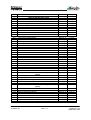
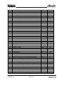

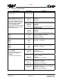
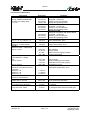
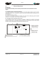
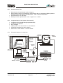

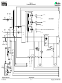
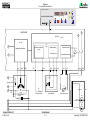
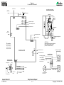
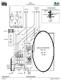
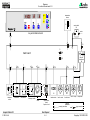
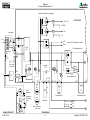
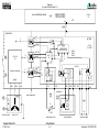
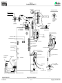
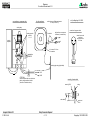
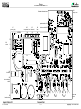

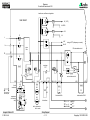
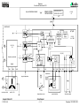
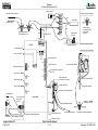
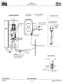
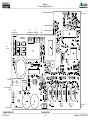
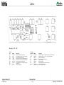
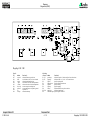
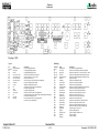
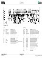

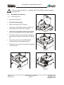
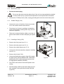
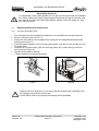
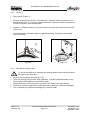

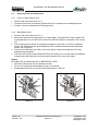
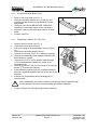

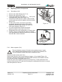
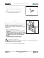
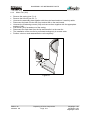
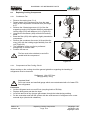
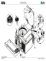
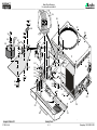
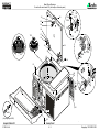
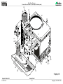
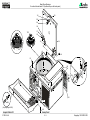
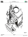
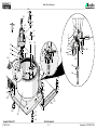
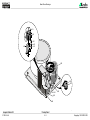
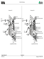

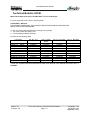
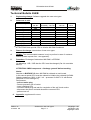
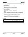


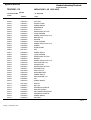
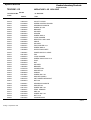

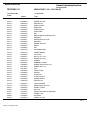


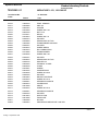

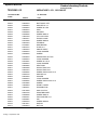
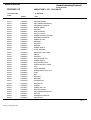
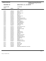

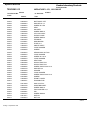

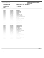
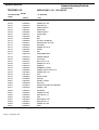
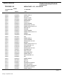

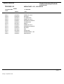
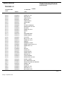

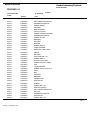

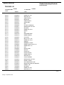
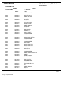


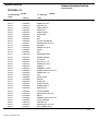
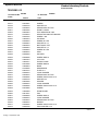
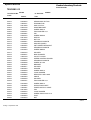
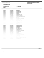


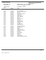
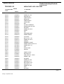
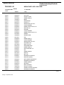
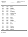


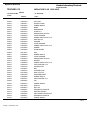

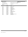


![Overview DR120 Service manual [v00]](http://vs1.manualzilla.com/store/data/006012884_1-f54ceab96779dba42a616edbeea41727-150x150.png)