1
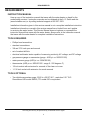
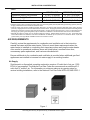
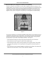
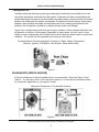
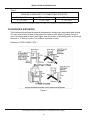
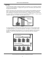
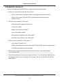
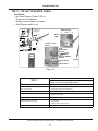
Service Handbook
COMMERCIAL GAS WATER HEATERS
MODEL BTR 500/A SERIES 120/121
500 Tennessee Waltz Parkway
Ashland City, TN 37015
INSTALLATION
CONSIDERATIONS
- PRE
SERVICE
INSTALLATION
CONSIDERATIONS
- PRE
SERVICE
CHECKS - OPERATION
&
SERVICE
-TROUBLESHOOTING
CHECKS - WATER HEATER CONSTRUCTION OPERATION & SERVICE - TROUBLESHOOTING
SERVICING SHOULD ONLY BE PERFORMED BY A QUALIFIED SERVICE AGENT.
PRINTED IN THE U.S.A 0510
1
318349-000
COMMERCIAL GAS WATER HEATER
SERVICE MANUAL
TABLE OF CONTENTS
INTRODUCTION ............................................................3
Gas Control Valve/Burner Area View ......................18
Qualifications ...........................................................3
Blower Prover Switch - Settings .............................19
Service Warning........................................................3
Thermostat and Ignition control Board View ...........20
Service Reminder .....................................................3
White Rodgers Integrated Control - Thermostat .....21
REQUIREMENTS...........................................................4
White Rodgers Ignition Control Board ....................21
Instruction Manual ....................................................4
Pre-Service Checklist .............................................22
Tools Required ..........................................................4
TROUBLESHOOTING .................................................23
Tools Optional ...........................................................4
Ignition Control Board: Error Codes........................23
INSTALLATION CONSIDERATIONS .............................5
1 Flash ..............................................................23
Water Piping .............................................................5
2 Flashes ..........................................................23
Closed Water Systems........................................5
3 Flashes ..........................................................24
Thermal Expansion .............................................5
4 Flashes ..........................................................24
Gas Pressure Requirements ....................................5
6 Flashes ..........................................................24
Air Requirements ......................................................6
7 Flashes ..........................................................24
Air Supply............................................................6
8 Flashes ..........................................................25
Insufficient Make-up Air, Negative Air Pressure,
and Downdrafts ...................................................7
Continuous Flash ..............................................25
Continuous On ..................................................25
Make-up Air: Direct Communication with Outdoors ...................................................................8
Integrated Heater Control: Display Lights ..............26
Test 1: 120 VAC to Heater Check ...........................27
Contaminated Air ................................................9
Test 2: Polarity Check .............................................28
Clearances (Water Heater) .......................................9
Test 3: Continuity Check of High Limit (ECO) .........29
Clearances (Exterior) ..............................................10
Test 4: Upper Temperature Probe
Continuity Check.....................................................30
Venting .................................................................... 11
OPERATION AND SERVICE .......................................12
Test 5: Calling for Heat - No Blower Operation .......31
Sequence of Operation ...........................................12
Test 6: Blower On, No Ignition ................................32
Electrical Sequence ................................................13
Wiring Diagram .......................................................14
Test 7: Blower On, Blower Prover Switch Closed,
No Igniter Operation ...............................................33
Operating Sequence - Flow Chart ..........................15
Test 8: Igniter Heats, No Main Burner.....................34
Gas Control Valve ..................................................16
Test 9: Igniter Heats, No Main Burner.....................35
Measuring Gas Pressures ................................16
Test 10: Main Burner Ignition for Less than
Five Seconds ..........................................................36
Manifold Pressure Adjustment ..........................17
Test 11: Water Heater Shutting Off Below Setting ..37
Main Valve Solenoid Connections ....................17
Servicing should only be performed by a Qualified Service Agent
2
INTRODUCTION
INTRODUCTION
This Service Manual is designed to be an aid in servicing and troubleshooting A. O. Smith
Master-Fit models BTR 500 Series 120/121 commercial water heaters. The instructions
and illustrations contained in this service manual will provide you with troubleshooting
procedures to verify proper operation and to diagnose and repair common service
problems.
This Service Manual does not replace or supersede the instruction manual that came with
the water heater. Always refer to the instruction manual that came with the water heater for
complete installation instructions. If the instruction manual is not available, copies can be
obtained from the manufacturer’s web site or by calling the toll free phone number shown
on the back cover of this service manual.
QUALIFICATIONS
Servicing the products referenced in this manual requires the ability (in the field involved)
equivalent to that of a Qualified Service Agent as defined by the American National Standards
Institute (ANSI) below. Installation skills such as plumbing, air supply, venting, gas supply,
electrical supply are required in addition to diagnostic and electrical testing skills.
ANSI Z223.1 2006 Sec. 3.3.83: “Qualified Agency” - “Any individual, firm, corporation or
company that either in person or through a representative is engaged in and is responsible
for (a) the installation, testing or replacement of gas piping or (b) the connection,
installation, testing, repair or servicing of appliances and equipment; that is experienced in
such work; that is familiar with all precautions required; and that has complied with all the
requirements of the authority having jurisdiction.”
SERVICE WARNING
If you are not qualified (as defined by ANSI above) and licensed or certified as required by
the authority having jurisdiction to perform a given task, do not attempt to perform any of
the procedures described in this manual. If you do not understand the instructions given in
this manual, do not attempt to perform any procedures outlined in this manual.
SERVICE REMINDER
When performing any troubleshooting step outlined in this service manual, always consider
the wiring and connectors between components. Perform a close visual inspection of all
wiring and connectors to and from a given component before replacement. Ensure wires
were stripped before being crimped in a wire connector, ensure wires are crimped tightly in
their connectors, ensure connection pins in sockets and plugs are not damaged or worn,
ensure plugs and sockets are mating properly and providing good contact.
Failure to perform this critical step or failing to perform this step thoroughly often results in
needless down time, unnecessary parts replacement, and customer dissatisfaction.
Servicing should only be performed by a Qualified Service Agent
3
REQUIREMENTS
REQUIREMENTS
INSTRUCTION MANUAL
Have a copy of the instruction manual that came with the water heater on hand for the
model being serviced. Instruction manuals can be obtained at the A. O. Smith web site
(www.hotwater.com) or by calling technical support at 800 527-1953.
Installation information given in this service manual is not a complete installation instruction.
Installation information covered in this service manual has a limited focus as it applies
to servicing the water heater. This Service Manual does not replace or supersede the
instruction manual that came with the water heater. Always refer to the instruction manual
that came with the water heater for complete installation instructions.
TOOLS REQUIRED
• Phillips head screwdriver
• standard screwdrivers
• 3/8 and 7/16 inch open end wrench
• set of marked drill bits
• electrical multimeter tester capable of measuring continuity, AC voltage, and DC voltage
• gas pressure gauge or manometer (gauge - AOS pt. no. 9005033105)
• water pressure gauge (AOS pt. no. 9004792105)
• thermometer (AOS pt no. 9005423105 - range 0 - 220 degrees F)
• 1/2 inch socket with extension for removal of the clean out cover
• 1-1/16 inch socket with extension for anode removal
TOOLS OPTIONAL
• Two digital manometers range -20.00 to +20.00” W.C., resolution 0.01” W.C.
Recommend UEI model EM200, TPI model 620 or equivalent.
Servicing should only be performed by a Qualified Service Agent
4
INSTALLATION CONSIDERATIONS
INSTALLATION CONSIDERATIONS
Installation information given in this service manual IS NOT a complete installation
instruction. Installation information covered in this service manual has a limited focus as
it applies to servicing. This service manual does not replace or supersede the Instruction
Manual that came with the water heater. Always refer to the instruction manual that came
with the water heater for complete installation instructions.
If the instruction manual that came with the water heater is not on hand, copies can be
obtained from the manufacturer’s web site or by calling the toll free phone number shown
on the back cover of this service manual.
WATER PIPING
Closed Water Systems
Water supply systems may, because of code requirements or such conditions as high line
pressure, among others, have installed devices such as pressure reducing valves, check
valves, and back flow preventers. Devices such as these cause the water system to be a
closed system.
Thermal Expansion
As water is heated, it expands (thermal expansion). In a closed system, the volume
of water will grow when it is heated. As the volume of water grows, there will be a
corresponding increase in water pressure due to thermal expansion. Thermal expansion
can cause premature tank failure (leakage). This type of failure is not covered under the
limited warranty. Thermal expansion can also cause intermittent temperature-pressure relief
valve operation: water discharged from the valve due to excessive pressure build up. This
condition is not covered under the limited warranty. The temperature-pressure relief valve is
not intended for the constant relief of thermal expansion.
A properly sized thermal expansion tank should be installed on all closed systems to control
the harmful effects of thermal expansion. Contact a local Qualified Service Agency (page 3)
to have a thermal expansion tank installed.
GAS PRESSURE REQUIREMENTS
Table 1 shows supply and manifold gas pressure requirements for BTR 500/A 120 - 121
model water heaters. Supply gas pressure is the pressure of fuel gas being supplied to the
water heater. Manifold gas pressure is the pressure of the gas being supplied to the water
heater’s burners.
Supply gas pressure should be measured twice. One measurement while the water
heater is not firing (static) and again while the water heater is firing (dynamic). If the
supply gas pressure drops more than 1.5” W.C. between the static and dynamic pressure
measurements, this may indicate the gas line and/or gas regulator to the water heater is
undersized. See the gas line requirements in the Instruction Manual that came with the
water heater.
Servicing should only be performed by a Qualified Service Agent
5
INSTALLATION CONSIDERATIONS
Table 1
NATURAL GAS
10” W.C. (2.49 kPa)
5.2” W.C. (1.29 kPa)
3.5” W.C. (0.87 kPa)
‡
Maximum Supply Gas Pressure
†
Minimum Supply Gas Pressure
* Manifold Gas Pressure
PROPANE (LP) GAS
12” W.C. (2.99 kPa)
11” W.C. (2.74 kPa)
10” W.C. (2.49 kPa)
‡ Maximum supply pressure; readings are taken while gas is not flowing (static pressure) AND while gas is flowing (dynamic pressure).
Supply pressure must never exceed this maximum value.
† Minimum supply gas pressure; readings are taken while gas is not flowing (static pressure) AND while gas is flowing (dynamic
pressure). Supply pressure must never fall below the minimum values. Supply gas pressures should be measured with all gas fired
appliances conencted to a common main firing at full capacity. If supply pressure drops more than 1.5” W.C. as gas begins to flow,
the supply gas system (gas line/regulator) may be restricted or undersized. See the instruction manual for more information.
* Manifold gas pressure; reading can only be taken while gas is flowing. Reading taken should be ± 0.3” W.C. of the listed value.
These water heaters are certified for use without modification for altitudes up to 10,000 feet. For elevations above 10,000 feet
(3,048 meters), see High Altitude Installations section of instruction manual.
AIR REQUIREMENTS
Carefully review the requirements for combustion and ventilation air in the instruction
manual that came with the water heater. Failure to meet these requirements when the
water heater is installed or overlooking their importance when servicing the water heater
often results in operational problems (some are listed below), needless down time,
unnecessary parts replacement, and customer dissatisfaction.
Ensure additional air for combustion and ventilation is provided when additional gas fired
appliances are installed to increase hot water supply in an existing location.
Air Supply
Stoichiometric or theoretical complete combustion requires 10 cubic feet of air per 1,000
BTUH of gas supplied. The National Fuel Gas Code also recommends an additional 2.5
cubic feet of “excess” air. For information on minimum make-up air opening sizes for
various building installations, refer to the National Fuel Gas Code NFPA 54, ANSI Z223.1.
Figure 1
Servicing should only be performed by a Qualified Service Agent
6
INSTALLATION CONSIDERATIONS
Insufficient Make-up Air, Negative Air Pressure, and Downdrafts
A lack of combustion and ventilation air can create a negative ambient air pressure in the
installed space. The vent system on one or more gas fired appliances can experience down
drafts due to the outdoor air pressure being greater than the ambient air pressure in the
installed space. Where multiple gas fired appliances are installed, one or more gas fired
appliances can “pull air” through the vent system(s) of other appliances installed nearby.
Downdraft Caused by Kitchen Vent Hood
Figure 2
One common example is in a restaurant installation where exhaust vent equipment was not
considered in sizing make-up air requirements. This condition may result in air being back
drafted by the restaurant exhaust equipment through the water heater, causing the draft
proving switch to open and/or erratic heater shutdown. See Figure 2.
• Down drafts can cause poor mixing of fuel gas and combustion air in the burners.
• Down drafts can cause flue gases to spill into the installed space.
• Down drafts can cause common service problems such as ignition failure. Down drafts
can sweep pilot gas away from the spark igniter during ignition and prevent ignition of
the pilot.
• Down drafts may cause extremely dangerous conditions such as flame rollout where the
flames from the main burner “roll out” of the combustion chamber.
Servicing should only be performed by a Qualified Service Agent
7
INSTALLATION CONSIDERATIONS
Make-up Air: Direct Communication with Outdoors
A fresh supply of make-up air for combustion can be supplied to the water heater through
make-up air ducts, which directly communicate with the outdoors. (Not Direct Vent.)
Two openings are required: one within 12 inches of the top of the enclosure and one
within 12 inches of the bottom of the enclosure. Each opening must have a free area of
not less than 1 square inch per 4,000 BTUH of the total input of all appliances within
the enclosure. The lower opening primarily provides combustion air. The upper opening
provides vent dilution air and acts as a relief opening for flue gases should the vent become
obstructed or a downdraft condition occur.
Figure 3
Additionally, when the water heater is installed in a confined space and communicating with
the outdoor air, one permanent opening, beginning within 12 inches (30 cm) of the top of
the enclosure, must be permitted where the equipment has clearances of at least 1 inch
(2.5 cm) from the sides and back, and 6 inches (16 cm) from the front of the appliance. The
opening must directly communicate with the outdoors and must communicate through a
vertical or horizontal duct to the outdoors or spaces (crawl or attic) that freely communicate
with the outdoors, and must have a minimum free area of a) 1 square inch per 3,000 BTUH
(7cm2 per kW) of the total input of all equipment located in the enclosure and b) not less
than the sum of the areas of all vent connectors in the confined space.
Servicing should only be performed by a Qualified Service Agent
8
INSTALLATION CONSIDERATIONS
Contaminated Air
Carefully review the warnings concerning contaminated combustion and ventilation air in the
instruction manual that came with the water heater. Combustion air that is contaminated can
greatly diminish the life span of the water heater and water heater components such as burners,
igniters, flue baffles and vent system components. Propellants of aerosol sprays, beauty shop
supplies, water softener chemicals and chemicals used in dry cleaning processes that are
present in the combustion, ventilation or ambient air can cause such damage.
Vapors from volatile compounds such as solvents, cleaners, chlorine based chemicals and
refrigerants in addition to being highly flammable in many cases, can also react to form
highly corrosive substances such as hydrochloric acid inside the water heater’s combustion
chamber. The results can be hazardous and cause product failure.
Contaminated Air Causes Aggressive Corrosion of Water Heater Components
(Burners, Igniters, Flue Baffles, Vent System, Sheet Metal Parts)
Figure 4
CLEARANCES (WATER HEATER)
A 24-inch clearance for all serviceable parts is recommended. See also Figure 5 and
Table 2. You may also refer to the instruction manual or to the label on the water heater
for clearances applicable to your specific model.
Minimum Clearances to Combustible Surfaces
Figure 5
Servicing should only be performed by a Qualified Service Agent
9
INSTALLATION CONSIDERATIONS
Table 2
MINIMUM CLEARANCES TO COMBUSTIBLE SURFACES
“A” - Right Side
5” (12.7 cm)
“B” - Left Side
5” (12.7 cm)
“C” - Back
5” (12.7 cm)
A, B, and C clearances to non-combustible surfaces is “0” inches. A 20” clearance to cover remains unchanged.
CLEARANCES (EXTERIOR)
The illustration below shows the required clearances for venting units using natural draft venting.
The vent must extend at least 3 feet above the highest point where it passes through a
roof of a building and at least 2 feet higher than any portion of a building within a horizontal
distance of 10 feet (for vents of 12 inches in diameter or less).
Reference: NFPA 54 ANSI Z 223.1.
Figure 6
Servicing should only be performed by a Qualified Service Agent
10
INSTALLATION CONSIDERATIONS
VENTING
The BTR 500 water heater is classified by ANSI as a Category I (non-condensing, negative
pressure venting) appliance. It is approved for type B vent. The blower (draft inducer) does
not pressurize the exhaust.
NOTE: This section of the service manual is not a complete venting installation instruction.
Refer to the instruction manual that came with the water heater; ensure the venting has
been installed per all instruction manual requirements. Installation must also conform with
the current edition of the National Fuel Gas Code (NFPA 54/ANSI Z223.1). Costs to correct
installation errors are not covered under the limited warranty.
Chimney
A minimum of 1/4”
rise per foot of
horizontal vent is
required.
Figure 7
For larger applications, BTR 500 water heaters can be common vented together, either
in a tapered manifold or a constant size manifold. See Figure 8. In such cases, follow
the National Fuel Gas Code requirements for the sizing and installation of fan-assisted
products. The BTR 500 model may be common vented only with other Category I
appliances.
Tapered Manifold
Constant Size Manifold
Figure 8
Servicing should only be performed by a Qualified Service Agent
11
OPERATION AND SERVICE
OPERATION AND SERVICE
SEQUENCE OF OPERATION
1. Call for heat is activated when temperature sensed from Thermistor Probes falls below
the Thermostat setting.
2. Blower (Draft Inducer) is energized.
3. Ignition Control Board verifies that the Blower Prover Switch is closed and that the
Blower (Draft Inducer) is operating.
4. Igniter is energized.
5. Gas Valve is energized and burners ignite
6. Ignition Control Board verifies flame at burners.
7. Water is heated to Thermostat set point.
8. Gas Valve is de-energized.
9. Blower runs for purge period and is de-energized.
10. Ignition Control Board goes into standby mode and Blower Prover Switch Opens.
Blower (Draft Inducer)
Thermistors
(probes)
Main Gas
Valve
Main
Burner
Hot Surface Igniter
(Not Shown)
Figure 9
Servicing should only be performed by a Qualified Service Agent
12
OPERATION AND SERVICE
ELECTRICAL SEQUENCE
1. Switch Power on to unit.
2. Thermostat calls for heat.
3. Ignition Control Board performs diagnostic check on system components.
4. On completion of diagnostics check, the Ignition Control Board energizes the Blower
(Draft Inducer).
5. The Blower (Draft Inducer) begins drawing air through appliance, closing the Blower
Prover Switch.
6. On completion of Blower Prover Switch engagement, the Ignition Control Board begins
the ignition cycle.
7. The Ignition Control Board provides power to the Silicon Nitride Igniter.
8. The Silicon Nitride Igniter heats up for approximately 17 to 20 seconds.
9. At the end of Silicon Nitride Igniter’s warm-up, the Ignition Control Board opens the
Gas Valve.
10. From the time the Gas Valve opens, the Ignition Control Board waits 3 seconds
and then shuts off power to the Silicon Nitride Igniter.
11. From the time the Silicon Nitride Igniter’s power is shut off, the Ignition Control
Board waits 3 more seconds to monitor the Flame Sensor.
12. If the Ignition Control Board does not detect flame at the burners, it will de-energize the
Gas Valve and run the Blower for approximately 20 seconds to purge the combustion
chamber. The Ignition Control Board then restarts at Step 7 for up to 2 more trials
for ignition. After the third failed trial for ignition, the Ignition Control Board locks out
for one hour. At the end of this lock out period, the Ignition Control Board will restart
at Step 3 for three more trials. NOTE: The one hour lock out period can be reset by
cycling power to the water heater off and on again.
13. If the Ignition Control Board detects a strong flame from the Flame Sensor, it will remain
in the heating mode until the Thermostat is satisfied.
14. When the Thermostat is satisfied, the Ignition Control Board will de-energize the Gas
Valve and run the Draft Inducer for approximately 20 seconds to purge the combustion
chamber. The Ignition Control Board will then go into standby mode.
Servicing should only be performed by a Qualified Service Agent
13
OPERATION AND SERVICE
WIRING DIAGRAM
R
BK
BK
INDUCER
R
UPPER
PROBE/
ECO
BLOWER PROVER
PRESSURE SWITCH
W
BK
Y
THERMOSTAT
R
TO EARTH
GROUND
R
BL
BR
IGNITION BOARD
R
BK
LOWER
PROBE
1a 1 1b
R
W
HOT 120 VAC
NEUTRAL
EARTH GROUND
G
IGNITER/FLAME
SENSOR
NOTE:
Must be properly grounded
and have correct polarity
connections.
R
R
120 VAC CIRCUIT
FACTORY INSTALLED
BY INSTALLER
W
WIRING DIAGRAM FOR BTR 500
WHEN EQUIPPED WITH WHITE-RODGERS IGNITION
BOARD, DIGITAL THERMOSTAT AND CONTROLS.
IN
IN
PSI
PSI
Y
OFF
OFF
IF ANY OF THE ORIGINAL WIRE AS SUPPLIED
MUST BE REPLACED USE ONLY TYPE 105 C
THERMOPLASTIC OR EQUIVALENT.
ON
ON
BK - BLACK
BR - BROWN
R - RED
Y - YELLOW
G - GREEN
BL - BLUE
W - WHITE
Y
Figure 10
! WARNING
Disconnect from electrical supply before servicing unit. Replace all doors and panels
before operating the water heater.
Servicing should only be performed by a Qualified Service Agent
14
OPERATION AND SERVICE
OPERATING SEQUENCE - FLOW CHART
Power On
Call for Heat
Self diagnostic check is performed
(Correct state of Blower Prover Switch and ECO is verified)
(polarity , earth ground , and Igniter presence are verified )
NO
Control Locks Out - LED
Displays 2, 6, or 8
Flash Error Code
(See Error Code Chart )
YES
Blower (Draft Inducer)
Motor is Energized
Blower Prover Switch (N.O.) Contacts
Close at – 2.85“ W.C. ± 0.13” W.C.
NO
Control Locks Out
Displays 3 Flash
Error Code
YES
Ignition Control Board
Sends Voltage (80-120 VAC)
to Igniter for 17-20 Seconds.
Ignition Control Board Energizes
Gas Valve (24 VAC)
Igniter De-energized After 3 Seconds
Below 0.1 uA DC Flame Sense:
Heater Will Try to Ignite 3 Times
Control De-energizes Gas Valve
Blower Runs for Post Purge Period
Control Locks Out for 1 Hour
Displays 1 Flash Error Code
Ignition Control Board Waits 3
More Seconds For “Strong” Flame
Sense Signal (2.0 uA DC or more)
NO
Between 2.0 and 0.1 uA DC Flame Sense
Heater Will Continue to Operate
Displays 7 Flash Error Code
(Weak Flame Sense)
YES
Tank Heated to Set -Point
Ignition Control Board
De-energizes Gas Valve
Blower Runs 60 Seconds
Post Purge Cycle and
Shuts Off
Blower Prover Switch Contacts Re-open
Ignition Control Board Goes into Standby Mode
Figure 11
Servicing should only be performed by a Qualified Service Agent
15
OPERATION AND SERVICE
GAS CONTROL VALVE
This gas valve is a 24 volt AC combination-step opening valve. It includes two valves
assembled in parallel, connected by a wiring harness. Note that the valves have fixed
pressure regulation and are not adjustable. However, the manifold (outlet) pressure is
adjustable as described on the next page.
IMPORTANT:
• For complete device shut-off, both gas control knobs must be in the OFF position.
• Both gas control knobs must be in the same position for operation or shutoff.
• Do not alter or remove the wiring harness.
• Do not apply a jumper across the valve lead wires or short them together.
Inlet
Inlet Pressure Taps
Main Gas
Regulators
Gas Control Knobs
(Outlet Pressure
Adjustment)
Manifold Pressure
Taps
Wiring Harness
Outlet
TOP VIEW OF GAS VALVE
Figure 12
Measuring Gas Pressures
The supply gas pressure is measured at the inlet pressure tap when the gas is flowing. The
manifold gas pressure is measured at the manifold pressure tap when the gas is flowing.
Servicing should only be performed by a Qualified Service Agent
16
OPERATION AND SERVICE
Manifold Pressure Adjustment
The main gas regulators are found beneath the silver or black cap screws. (Natural Gas
valves have silver caps; Propane valves have a black caps). Remove the caps to access
the outlet (manifold) pressure adjustment screw. IMPORTANT: Ensure that the outlet
pressure matches the manifold pressure that is listed on the water heater rating plate.
• Natural Gas valves are factory preset to 3.5 inches W.C. The full rate outlet pressure
range is between 3 and 5 inches W.C.
• Propane (LP) valves are factory preset to 10.0 inches W.C. The full rate outlet pressure
range is between 8 and 12 inches W.C.
• Caution: Always test the manifold pressure at the outlet when the gas is flowing.
Wiring Harness
Main Gas
Regulators
(Outlet Pressure
Adjustment)
Lead Wires
(24-Volt Main Valve
Solenoid Connections)
TOP VIEW OF GAS VALVE
Figure 13
Main Valve Solenoid Connections
The figure above shows the two 24-volt main valve (MV) solenoid connections. The two
yellow wires from the 12-pin ignition board plug connect to these leads.
Servicing should only be performed by a Qualified Service Agent
17
OPERATION AND SERVICE
GAS CONTROL VALVE/BURNER AREA VIEW
Honeywell Gas
Valve
Rollout Shield
Main Burner
Shield
Radiation
Shield
Main Burner with
Hot Surface Igniter
(HSI) mounted
Figure 14
Table 3
HOT SURFACE IGNITER (HSI)
Volts AC Nominal
80 VAC
Ohms Resistance
11.0 - 20.0 @
77° F (25° C)
NOTICE FLAME ROD CROSSES PATH OF
FLAME 0.1” to 0.25”.
Servicing should only be performed by a Qualified Service Agent
18
OPERATION AND SERVICE
BLOWER PROVER SWITCH - SETTINGS
Vent Connection
Exhaust/Outlet
Blower Prover Switch
Optional Hot Water Outlet
Blower (Draft Inducer)
Figure 15
Table 4
BLOWER PROVER SWITCH TABLE
BTR Model
500/A
Pressure Setting to Close Switch (Inches W.C.)
-2.85” ± 0.13”
NOTE: The Blower Prover Switch contacts are normally open and will close on a fall in
pressure. This will be a negative pressure (i.e., a vacuum).
Servicing should only be performed by a Qualified Service Agent
19
OPERATION AND SERVICE
THERMOSTAT AND IGNITION CONTROL BOARD VIEW
Figure 16
Servicing should only be performed by a Qualified Service Agent
20
OPERATION AND SERVICE
WHITE RODGERS INTEGRATED CONTROL - THERMOSTAT
Display
LED Label
Display
LEDs
Temperature
Adjustment
Dial
To Upper
Temp.
Probe
ECO Manual
Reset Button
To Ignition
Control
Board
E3
E1
E4
To Lower
Temp. Probe
120 VAC from
Ignition Control
Board
E2
Fuse
Pin Number
Label
Figure 17
WHITE RODGERS IGNITION CONTROL BOARD
Diagnostic LED Error
Flash Codes are
Displayed Here
120 VAC
Hot to
Thermostat
120 VAC Hot
from On/Off Switch
1 4 7 10
2 5 8 11
3 6 9 12
1, 3, 6 27, 10 89, 12 -
From Thermostat
Flame Probe
Blower Prover Switch
Ground
To Gas Valve (24 VAC)
4 3 2 1
120 VAC Neutral
from On/Off Switch
4, 2 - To Igniter (80-120 VAC)
3, 1 - To Blower (120 VAC)
120 VAC Neutral
to Thermostat
Figure 18
Servicing should only be performed by a Qualified Service Agent
21
OPERATION AND SERVICE
PRE-SERVICE CHECKLIST
Use the following checklist BEFORE you begin servicing the water heater.
1. Have you removed the cover from the controls?
• Did you take notice of the status lights on the upper water heater control?
• Did you take notice of the red LED in the upper left corner of the lower
ignition control?
2. Did you note conditions of the room?
• Where does the supply air come from?
• Is the room clean?
• What is stored with the heater?
• How is the heater vented?
• Are all water and gas shut-off valves open?
• Are there room exhaust or air intake fans?
3. Did you note the condition of the heater?
• Is the ON/OFF switch “On”?
• What is the temperature of the stored water? (Test at T&P valve or nearby faucet.)
• Is the thermal expansion tank installed?
4. Did you write down the complete model and serial number of the water heater?
If so, what are they?___________________________________________________
5. Does the heater have a good ground wire connection? If not, the blower (draft inducer)
will typically come on for a short time (3-5 seconds), then go off, and the red LED will
flash 8 times.
Servicing should only be performed by a Qualified Service Agent
22
TROUBLESHOOTING
TROUBLESHOOTING
IGNITION CONTROL BOARD: ERROR CODES
The White Rodgers ignition control board will display a flashing error code with an LED
light located on the upper left corner of the Ignition Control Board (Figure 18) when there is
a problem. There is a distinctive pause between a series of on/ off flashes (1 to 8 flashes)
when there is a problem. The following information describes the meaning of these error
“flash” codes and what should be checked and/or repaired. The 5 flash error code is not
used with this application.
NOTE: The Ignition Control Board varies the voltage to the Igniter to decrease wear. Lower
voltage results in a longer life for the Igniter. For this reason, voltage to the Igniter may
vary from 80 VAC to 120 VAC.
1 FLASH
System has locked out after 3 trials for ignition.
1
Check voltage (80-120 VAC) to igniter.
2
Check flame sense rod alignment.
3
Check igniter and flame sense rod wiring.
4
Check flame sense rod for corrosion; clean with steel wool.
5
Check igniter resistance. It should be 11 - 20 ohms.
6
Check ceramic insulator on igniter/flame sensor assembly for cracks. Replace if
damaged.
7
Check manifold gas pressure.
8
Check all molex plug connections; on integrated control, ignition control board, and
between the various components. Check the pin-to-pin contact between plugs; gently
wiggle suspected plug connections during operation.
2 FLASHES
Blower Prover Switch circuit was closed during self-diagnostic check at the
beginning of the heat cycle. Contacts should have opened at the end of last heat
cycle. Blower (Draft Inducer) will not start; call for heat “Status” LED will be illuminated on
integrated control.
1
Test continuity of blower prover switch; it should be open in “normal state” (blower not
running - wires removed)
2
Replace blower prover switch if continuity is present between terminals in normal state.
3
Check blower prover switch wiring, making sure that there are no jumpers on blower
prover switch.
Servicing should only be performed by a Qualified Service Agent
23
TROUBLESHOOTING
3 FLASHES
Blower prover (air pressure) switch failed to close its normally open contacts after
blower (draft inducer) was energized. Blower will run indefinitely, waiting for the blower
prover switch circuit to close.
1
Check air pressure reading at blower prover switch sensing port on blower fan housing
with manometer (digital preferred); blower must develop at least -2.85” W.C. (negative
pressure) before blower prover switch contacts will close.
2
Replace blower prover switch if pressure reading at the sensing port does drop to at
least - 2.85” W.C. and contacts remain open.
3
If pressure reading taken does not drop to at least - 2.85” W.C., check vent system
for obstruction, debris, and excessive elbows. Ensure vent system complies with
manufacturer’s and NFGC venting requirements for fan assisted Category I appliances.
4
Ensure there is neither a negative or positive air pressure in the equipment room (open
doors to outdoor atmosphere). This can cause the blower prover switch to malfunction.
Alleviate air pressure imbalance between the equipment room and the outside atmosphere.
5
Check the condition of the blower wheel in the blower; clean or replace as necessary.
4 FLASHES
ECO cutout (Energy Cut Off). Tank temperature has risen above 203°F and caused
lockout. ECO status LED on integrated control will also be illuminated. See Figure 17.
1
Determine if tank temperature is excessive and, if so, the possible cause (i.e.,
temperature control failing to cut out at set-point).
2
Cool tank to below 120°F to reset. ECO reset status LED will illuminate on the
integrated control when the control can be reset. Push reset button on integrated
control. See Figure 17.
3
Check continuity/resistance of temperature probes; clean off calcium build up.
6 FLASHES
Reversed polarity in power supply.
1
Interchange “hot” and “neutral” wire connections to the water heater.
7 FLASHES
Flame sensing is marginal; flame sense signal is below 2.0 micro-amps. Water heater
will continue to fire with flame sensing current over 0.1 micro-amp; below this, the control
will close the gas valve and ignition failure will occur.
1
Check flame sense rod alignment.
2
Clean flame sense rod with steel wool.
3
Check ceramic insulator on igniter/flame sensor for cracks. Replace if damaged.
Servicing should only be performed by a Qualified Service Agent
24
TROUBLESHOOTING
4
Check molex plug connector between igniter/flame sensor assembly and control board;
Also check flame sense (12 pin) plug connection at control board.
8 FLASHES
Igniter not sensed and/or water heater not grounded.
1
Test igniter resistance. It should should be 11 - 20 ohms. Replace igniter if open
continuity.
2
Ensure that the water heater is grounded. Check all ground wires on heater and
controls.
3
Check molex plug connector between igniter/flame sensor assembly and control board.
Also check igniter (4 pin) plug connection at control board.
CONTINUOUS FLASH
Flame sensed out of sequence; continuous flame sensed for more than 5 seconds
without gas valve being energized.
1
Ensure that the gas valve is not failing to close at the end of the heating cycle.
CONTINUOUS ON
Internal control board failure.
1
Replace ignition control board.
Servicing should only be performed by a Qualified Service Agent
25
TROUBLESHOOTING
INTEGRATED HEATER CONTROL: DISPLAY LIGHTS
Power
Call for
Heat
Energy Cut
Off Status
Reset
Status
LED
STATUS
INDICATION
ACTION
Calling for heat
Normal status. No action required.
The ECO (Energy Cut-Off) has
opened.
• Check for excessively hot water
(203° F or higher).
• Correct the problem
No power
Check the breaker.
Tank is at a set temperature ±
2° F.
No action required.
• Push the manual reset button.
Refer to Figure 17.
Tank has cooled
below 120° F.
Preceded by “ECO Open”
indication.
• Troubleshoot for the reason that the ECO
opened.
Servicing should only be performed by a Qualified Service Agent
26
TROUBLESHOOTING
TEST 1: 120 VAC TO HEATER CHECK
Conditions:
• No Green Display “Power” LED on.
• Plugs are in receptacles.
• Supply power breaker is not open.
• On/Off heater switch is on.
White Rodgers
I t
Integrated
t dC
Control
t l
TO EARTH
GROUND
Display
LEDs
BL
BR
R
BK
1a 1 1b
R
W
HOT 120 VA
V
C
VAC
NEUTRAL
EARTH GROUND
Ignition Control
Board
IGNITOR/FLAME
SENSOR
E2
R
R
(E14)
From Heater
Control
120 VA
V
VAC
C CIRCUIT
FACTORY
F
FA
CTORY INSTALLED
T
BY INSTALLER
T
W
120 V.
(E13) To ON/OFF
Switch
Supply Neutral
Ground
Groun
E9 Not Used
Figure 19
120 V. AC check to water heater ON/OFF switch
TEST 1
Check for 115-125 VAC black wire to ground\
115 VAC check to E13 Terminal and 2B receptacle.
IF.........
then............
voltage is not present from on/off switch center
black wire to ground
• check conditions above.
• check wiring from switch to break box.
Power is present from center on/off terminal
check power from on/off switch to ignition board terminal E13
Voltage is not present at E13 to ground
• check wiring from on/off. Left-outside terminal to E13.
• Replace on/off switch.
Power is present at E13
check power from E14 to water heater control E2 receptacle
Voltage is not present from water heater control
receptacle E2 black to ground
• check wiring from ignition control board E14 to water heater control
receptacle E2.
• Replace ignition control board.
Power is present at E2.
green LED should be on.
Servicing should only be performed by a Qualified Service Agent
27
TROUBLESHOOTING
TEST 2: POLARITY CHECK
Conditions:
• No hot water
• Green “Power” LED is on.
• Tank is more than 5° F below temperature dial setting.
• Red ignition control board diagnostic LED is flashing 6 times between pauses.
• Red, diagnostic “Call for Heat” LED-OFF.
Figure 20
TO EARTH
GROUND
120 V.
BL
BR
R
BK
1a 1 1b
R
W
HOT 120 VAC
NEUTRAL
EARTH GROUND
IGNITOR/FLAME
SENSOR
R
R
W
120 VAC CIRCUIT
FACTORY INSTALLED
BY INSTALLER
Ground
Figure 21
TEST 2
Polarity Check
Check from on/off switch center and white wire terminals to ground
IF.........
then............
115-125 VAC is not present
see Test 1.
Voltage is present white (right terminal) to ground
but not black (center terminal) to ground
reverse supply wire connections. Polarity is reversed.
Servicing should only be performed by a Qualified Service Agent
28
TROUBLESHOOTING
TEST 3: CONTINUITY CHECK OF HIGH LIMIT (ECO)
Conditions:
• Power On – No Hot Water
• Red, heater control “Call for Heat” LED – on
• Red ignition control board diagnostic LED – 4 Flashes
• Note LED Flash Code before resetting water heater control.
• See Ignition Control Board: Error Codes.
• Turn Power OFF.
Figure 22
TEST 3
Continuity check of ECO
(energy cut-off, high limit)
Black to Black wires of upper probe.
Power is off.
IF.........
Then............
continuity is indicated
(ZERO “0.0” Resistance)
opens at 203° F; closes at 193° F. If water is below 193° F, continuity is correct.
continuity is not present
(meter reads “0.L”)
replace ECO sensor if water temperature is below 193° F.
water is less than 120° F
• reset status LED should be on.
• replace heater control if control will not manually reset.
Servicing should only be performed by a Qualified Service Agent
29
TROUBLESHOOTING
TEST 4: UPPER TEMPERATURE PROBE CONTINUITY CHECK
Conditions:
• Power On - Water below temperature set point.
• Red, water heater control “Reset Status” LED-OFF
• “Call For Heat” LED off.
Upper Temperature probe continuity check
TEST 4
Red wire to red wire - Turn supply power “Off” for this test
IF.........
then............
Test indicates no continuity
replace probe.
Continuity is indicated
Probe should be okay.
(Also verify Ohms resistance for water temperature. Reading will be approximate.)
Figure 23
Table 4
OHMS RESISTANCE TABLE
°F
Ohms
70°
11,884
120°
3,759
140°
2,488
180°
1,169
Servicing should only be performed by a Qualified Service Agent
30
TROUBLESHOOTING
TEST 5: CALLING FOR HEAT - NO BLOWER OPERATION
Conditions:
• Power on
• Plugs in Receptacles
• Red “ Call for Heat” LED - ON
• Blower (Draft Inducer) off
Note flash code on ignition control board diagnostic LED.
Water Heater Control - Thermostat
“Call for Heat”
LED Indicator
Diagnostic LED
Indicator
120
Ignition Control Board
Ground
Figure 24
TEST 5
IF.........
then............
Pin 1 to ground check has no voltage
• reset control by interrupting power. Note possible reasons for this from flashing LED code.
• replace ignition board.
Pin 1 to ground has voltage
Proceed
Pin 3 to ground has no voltage
• check wiring harness and plugs.
• replace blower.
Servicing should only be performed by a Qualified Service Agent
31
TROUBLESHOOTING
TEST 6: BLOWER ON, NO IGNITION
Conditions:
• Power on
• Plugs in receptacles
• Blower (Draft Inducer) operating
• No power to Hot Surface Igniter (HSI). Note LED flash code.
Blower
Prover Switch
Hot Water Outlet
Blower
Exhaust
Blower
(Draft Inducer)
Check E4 pin 2 to ground
Figure 25
TEST 6
24 VAC Check of Blower Prover Switch Circuit
IF.........
then............
ignition board receptacles E1, Pin 7 to ground
shows no voltage
replace Ignition board.
E1, Pin 7 has 24 Volt to ground
check wire connection to and from blower (draft inducer).
voltage check of each blower switch terminal to
ground shows voltage to only 1 terminal
•
•
•
•
switch is open. Check for proper draft (should also see LED 3 flash code).
check for blocked exhaust.
check that blower outlet exhaust damper is open.
replace blower prover switch.
Servicing should only be performed by a Qualified Service Agent
32
TROUBLESHOOTING
TEST 7: BLOWER ON, BLOWER PROVER SWITCH CLOSED, NO IGNITER
OPERATION
Conditions:
• Power on, but no power to igniter
• Plugs in receptacles
• Blower (Draft Inducer) on
• 24V at ignition board E1, Pin 10
Check E4 pin 4 to Ground
Check E1 pin 10 - 24V
Ground
Continuity
Test
Check E4 pin 2 to Ground
4
3
2
1
E4 Plug
Ground
Figure 26
Voltage check and continuity check of hot surface igniter circuit
TEST 7
Continuity check - Power off- Plug removed from E4 receptacles.
Nominal 80 VAC check - Plug in E4- Power on.
IF.........
then............
Continuity is not indicated between E4 plug
pin 2 to 4.
• check wiring and connection from E4 plug to HSI receiving plug.
• replace HSI Assembly.
Continuity is present
Resistance should be between 11 and 20 Ohms at a temperature of 77°F.
Voltage is not present between E4, Pin 2 to ground
Replace ignition board.
Voltage is present
Continue
Voltage is not present between E4, Pin 4 to
ground
• check wiring and plug connections to hot surface igniter (HSI).
• replace HSI if needed.
Voltage is present
Note ignition board flash code LED. Hot surface igniter (HSI) should work.
Servicing should only be performed by a Qualified Service Agent
33
TROUBLESHOOTING
TEST 8: IGNITER HEATS, NO MAIN BURNER
24 V.
E1 Plug to Pin 9
E1 Plug to Pin 12
Figure 27
TEST 8
IGNITER HEATS......NO MAIN BURNER
IF.........
then............
short heat up time of igniter
check control box grounding.
Normal warm up (Approximately 20 seconds) No ignition
check for 24V from E1, Pin 12 to ground during 4 second trial. If Yes, continue. If No,
replace Ignition Board
No voltage present E4, Pin 12 to ground
replace ignition board.
24 Volt was present from E1, Pin 12 to ground,
but no main burner
• check that air has been purged from gas circuit.
• check that wiring and connections to gas valve and E1, Pin 9 are correct.
• check for 24 VAC at E1, Pin 9 to ground during 4 second trial for ignition.
Servicing should only be performed by a Qualified Service Agent
34
TROUBLESHOOTING
TEST 9: IGNITER HEATS, NO MAIN BURNER
Conditions:
• Test 8 completed
• Turn off power
• Disconnect wires from gas valve
Inlet
Manifold
Pressure
Tap
Manifold
Pressure
Tap
Measure Resistance
Between Gas Valve
Terminals (Main Valve
Solenoid Connections)
Outlet
Figure 28
TEST 9
IGNITER HEATS – NO MAIN BURNER
IF.........
then............
Meter reads 0 or 1
• Check meter scale setting; verify that it is set to read between 550 and 650 Ohms.
• replace the gas valve
Meter indicates pilot and main coil have
continuity
valve should be okay. However, if there is still no gas to the main burner, the coil
may be stuck. Replace the gas valve.
Servicing should only be performed by a Qualified Service Agent
35
TROUBLESHOOTING
TEST 10: MAIN BURNER IGNITION FOR LESS THAN FIVE SECONDS
Conditions:
• Power On; plug connected
• Main Burner ignites for approximately five seconds, then goes out.
• Tests 8 and 9 completed
Note the flash code on the ignition board LED.
Hot Surface Igniter (HSI)
HSI Mounted on Main Burner
E1, Pin 2 (From Flame Proving Rod)
Figure 29
TEST 10
MAIN BURNER IGNITION FOR LESS THAN FIVE SECONDS
IF.........
then............
no extended main burner ignition
• check wiring and plug connections of hot surface igniter (HSI) assembly plug and
ignition board receptacles E1, Pin 2.
• verify that HSI assembly is not cracked or dirty.
• verify that flame prover will be in main flame.
• replace HSI assembly.
still no extended main burner ignition
replace ignition control board.
Servicing should only be performed by a Qualified Service Agent
36
TROUBLESHOOTING
TEST 11: WATER HEATER SHUTTING OFF BELOW SETTING
Conditions:
• Main burner ignited
• Stored water is below temperature setting more than 5° F (Tank Average).
• Power off
• Plug disconnected from heater control board receptacle E3 and E4
E3
E4
Figure 30
TEST 11
WATER HEATER SHUTTING OFF BELOW SETTING
(Water Temperature Circuit Check - Continuity)
IF.........
then............
Continuity check pin to pin of lower temperature
probe shows 1 or 0 (E4)
See Test 4.
• check wiring and plug connections to heater control board receptacle E4.
• replace lower temperature probe.
Continuity check red wire pin to red wire pin on
upper temperature sensor shows 1 or 0 (E3)
See Test 4.
• check wiring and plug connections to heater control board receptacle.
• replace upper temperature probe.
All above checks are okay
• Check wiring and plug connections to heater control board receptacle.
• Replace upper temperature probe.
Servicing should only be performed by a Qualified Service Agent
37
NOTES
Servicing should only be performed by a Qualified Service Agent
38
NOTES
Servicing should only be performed by a Qualified Service Agent
39
500 Tennessee Waltz Parkway, Ashland City, TN 37015
Technical Support: 800-527-1953 • Parts: 800-433-2545 • Fax: 800-644-9306
www.hotwater.com
Copyright © 2010 A.O. Smith Corporation. All rights reserved.