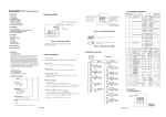
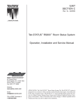
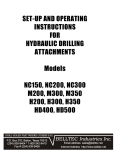
1
IL380
SECTION E
Rev. 20 - 03/2011
Tek-CARE® NC150 and NC200
Intercom Nurse Call Systems
UL® 1069 Listed
Operation, Installation and Service Manual
Distributed by:
Alpha Communications®
42 Central Drive
Farmingdale, NY 11735-1202
Phone: (631) 777-5500
Fax: (631) 777-5599
Website:
www.AlphaCommunications.com
Email:
[email protected]
TOLL-FREE Technical #:
1-800-666-4800
Tek-CARE® NC150 and NC200 series Intercom Nurse Call Systems are designed for nursing
home or individual hospital ward use. The Tek-CARE® NC150 and NC200 systems provide
selective two-way audio and visual communication from master station to staff and patient
stations, as well as emergency signaling and call indication from remote locations.
Emergency calls are indicated by a rapid pulsing of all audible and visual signals associated
with the calling station. Emergency calls take precedence over normal calls and can only
be canceled at the point of origin.
Operation, Installation and Service Manual
Copyright © 2001–2011 TekTone® Sound & Signal Mfg., Inc., All rights reserved.
No part of this publication may be copied without the express written permission of TekTone® Sound & Signal Mfg., Inc. The
content of this manual is furnished for informational use only, is subject to change without notice, and should not be construed as
a commitment by TekTone® Sound & Signal Mfg., Inc. TekTone® Sound & Signal Mfg., Inc. assumes no responsibility or liability
for any errors or inaccuracies that may appear in this documentation.
TekTone, the TekTone logo, Tek-Call, Tek-Care, Tek-Check-In, Tek-Com, Tek-Digicare, Tek-Door, Tek-Entry III, Tek-Guard, TekMicro, Tek-Micro II, Tek-MMARS II, TekNIOS, TekNIOS II, Tek-Paging, Tek-Phone, Tek-Safe, Tek-Select II, Tek-Sentry, TekSound, Tek-Status, Tek-Trio and Tek-View are either registered trademarks or trademarks of TekTone® Sound & Signal Mfg., Inc.
in the United States and/or other countries. All other trademarks are the property of their respective owners.
ii • IL380 Tek-CARE® NC150 & NC200 Manual
Copyright © TekTone Sound & Signal Mfg., Inc. All Rights Reserved.
Table of Contents ————————————————————
A Word About ESD (Electrostatic Discharge) ....................................... iv
System Operating Instructions ............................................................... 1
NC150N, NC200N Master Stations ........................................................................... 1
IR150B Staff Stations ................................................................................................ 3
IR151B, IR152B Patient Stations .............................................................................. 5
IR155B Patient Stations ............................................................................................. 5
SF155B Emergency and SF156B Code Stations ....................................................... 5
LI150B Duty Stations ................................................................................................. 5
LI381 Corridor Lights ................................................................................................ 6
LI382 & LI382LED Corridor Zone Lights ................................................................ 6
System Installation ................................................................................... 7
Installation Procedure ................................................................................................. 7
Equipment Locations .................................................................................................. 7
Wiring Installation ..................................................................................................... 8
Housing Installation ................................................................................................... 9
Wire Checkout .......................................................................................................... 10
Wire Connections .................................................................................................... 10
Connections Checkout .............................................................................................. 11
System Test Instructions ........................................................................................... 11
System Checkout and Testing .................................................................................. 11
System Maintenance Instructions ........................................................ 13
NC150N, NC200N Master Stations ......................................................................... 13
PK151A, PK152 Power & Control Units ................................................................ 14
IR150B Staff and IR155B Patient Stations .............................................................. 14
PK800A Secondary Power Supply ........................................................................... 14
FZ151 In-Line Fuse Holder ...................................................................................... 14
IR151B, IR152B Patient Stations ............................................................................ 15
SF155B Emergency and SF156B Code Stations ..................................................... 15
LI150B Duty Stations ............................................................................................... 15
LI381 Corridor and LI382 Corridor Zone Lights ................................................... 15
Replacement Parts .................................................................................................... 16
Illustrations & Wiring Diagrams
Figure 1—NC150N and NC200N Control Locations ................................................ 2
Figure 2—Duty, Staff, Patient, Emergency & Code Station Control Locations ........ 4
Figure 3—Master Panel Housing Chart and Wall Cut-Out Details ......................... 8
Figure 4—Panel Removal and Replacement ............................................................. 8
Figure 5—Ring and Back Box for IR150B, IR151B, IR152B and IR155B ............. 9
Figure 6—Ring and Back Box for SF155B, SF156B, LI150B,
LI381, LI382 and LI382LED .............................................................................. 9
Figure 7—SS106 Transformer Installation ............................................................. 10
Figure 8—NC150N, NC200N Selector Lamp/Switch
Lens, Filter and Lamp Replacement ................................................................. 13
Figure 9—NC150N, NC200N Nurse Call Systems Notes and Electrical Ratings . 17
Figure 10—Block Wiring Diagram without Zone Lamps ..................................... 18
Figure 11—Block Wiring Diagram with Zone Lamps ............................................ 19
Figure 12—NC150N, NC200N Wiring Diagram ................................................... 20
Figure 13—NC150N, NC200N, Two Stations in Parallel ....................................... 21
Figure 14—PK153 Wiring Diagram with Smoke Detector .................................... 22
Figure 15—PK153 Wiring Diagram with SF156B Code Station ........................... 23
Figure 16—PK151A or PK152 to PK800A Interconnection .................................. 24
Figure 17—SK151N Switch Board PCB Assembly ................................................ 25
Figure 18—SF337C Cross Reference Diagram ....................................................... 26
Figure 19—SF339 Cross Reference Diagram .......................................................... 27
Figure 20—NC110N Hookup to NC150N, NC200N .............................................. 28
Copyright © TekTone Sound & Signal Mfg., Inc. All Rights Reserved.
IL380 Tek-CARE® NC150 & NC200 Manual • iii
A Word about ESD (Electrostatic Discharge)————————
What Is It? Static electricity is a result of triboelectric charging of two dissimilar
nonconductive materials that are rubbed together, such as rubbing your feet on a carpet on
a cold winter day or in a dry climate. The resulting charge is detected when you reach out
to touch a doorknob or some other metallic object. The resulting discharge may only be
startling or, in severe cases, it may even be painful. The actual electrical charge is dependant
on the materials being rubbed together, humidity, the rate of separation, and other factors.
What Can It Do? While this effect may be disturbing to humans, the effect on electronic
equipment is often more serious, ranging from operational disruption to actual component
damage. These effects result from the high voltages that may be developed. The simple act
of walking across a carpet may develop as much as 30,000 volts, and changing a bed sheet
may create a charge of 100,000 volts or more. Such voltages readily cause arcing (the
spark that can be observed when you grab a doorknob after walking across a carpet, etc.).
The arcing is evidence of the discharge path. Due to the high voltage involved, the discharge
current can jump to any nearby metallic or non-metallic object. If the discharge is to or
through an electronic device, such as the nurse call system, the operation of the device may
be affected. If the discharge current passes through internal components, these components
may be damaged or their operation degraded.
What Can We Do About It? The manufacturer of the nurse call equipment has already
taken steps to protect the equipment from electrostatic discharge (ESD) effects. However,
since the cause is not in the equipment, but in the environment, further measures are
required of the installer and the user to achieve complete protection.
What The Installer Can Do: In humid climates or in places where the relative humidity is
kept at 65% or greater, there will likely be few problems with ESD. Where problems may
occur the following measures can be taken.
•
Ground all exposed metal surfaces. Grounding should be to a #16 gauge or larger
conductor.
•
Install nurse call system wiring in metal conduit. This conduit may be used to ground
panels.
•
Use shielded cable for nurse call system station-to-station wiring. The use of open
conductors invites inductive coupling of discharge currents, which can cause the
same problems as direct discharge currents.
•
Ground your body before handling system components. This can be done by using a
wrist strap, or simply by contacting a grounded metal surface. Use caution to avoid
hazardous voltages while grounded.
What The User Can Do: The most common generation of ESD in hospitals is due to
changing linen on hospital beds while the patient call cord or pillow speaker is still connected
to the nurse call system. The following precautions will help.
Remove the call cord or pillow speaker from the bed before changing the linen. It will be
necessary for the nursing staff to discharge themselves by contacting a grounded metal
object before placing the call cord or pillow speaker back on the bed; otherwise a spark will
jump to the nurse call equipment, causing the very damage they are trying to avoid. To
avoid a shock while discharging static electricity on the body, hold a metal object, such as
a key, and use that object to contact the grounded surface.
This information is provided to make you aware of ESD problems so that precautions may
be taken to avoid damage and disruption of system operation.
iv • IL380 Tek-CARE® NC150 & NC200 Manual
Copyright © TekTone Sound & Signal Mfg., Inc. All Rights Reserved.
System Operating Instructions ——————————————
This section provides complete operating instructions for all Tek-CARE® functions, as
well as reference drawings for use in locating and describing all controls. System operators
must read the following operating instructions concerning system equipment and the terms
used in conjunction with the equipment.
NC150N, NC200N Master Stations
Refer to Figure 1 for locations, names, and functions of controls and indicators.
Answer Normal Calls:
Normal calls are indicated by simultaneous operation of the following signals:
•
Steady illumination of the associated station selector lamp which is marked to
indicate call origin.
•
Steady illumination of call lamp.
•
Slowly pulsing audible tone. The audible call signal may be canceled for normal calls
by pressing the TONE OFF button. The button will then illuminate to indicate the tone
is silenced. Pressing the TONE OFF button when illuminated resets the call tone.
To establish conversation with the calling station, press the associated station selector
button. The remote station’s RESET lamp will illuminate. To speak to the caller, press
the TALK button while speaking and release to listen.
When the conversation is complete, press the associated station selector button to release
the station. The remote station’s RESET indicator will turn off. Normal calls placed from
an IR155B Station must be canceled at the point of origin.
Answer Normal Calls Using Optional TA150N or TA200N Handset:
To establish conversation with the calling station, press the associated station selector
button. The remote station’s RESET lamp will illuminate. To speak to the caller, lift the
handset from the cradle and begin normal two-way conversation. When the conversation
is complete, press the associated station selector button to release the station. The remote
station’s RESET lamp will turn off. Replace the handset in the cradle. Normal calls
placed from an IR155B Station must be canceled at the point of origin.
Answer Emergency Calls:
All emergency calls take precedence over any normal call signal. Emergency calls
must be answered in person and can only be canceled from point of origin. Emergency
calls are indicated by simultaneous operation of the following signals:
•
Rapid flashing of the associated station selector lamp, which is marked to indicate
call origin.
•
Rapid flashing of call lamp.
•
Rapidly pulsing audible tone.
Answer Code Calls:
All code calls take precedence over any normal or emergency call signal. Code calls
must be answered in person and can only be canceled from point of origin. Code calls
are indicated by simultaneous operation of the following signals:
•
Very rapid flashing of the associated station selector lamp (twice the rate of
emergency call), which is marked to indicate call origin.
•
Very rapid flashing of call lamp (twice the rate of emergency call).
•
Very rapidly pulsing audible tone (twice the rate of emergency call).
Copyright © TekTone Sound & Signal Mfg., Inc. All Rights Reserved.
IL380 Tek-CARE® NC150 & NC200 Manual • 1
Figure 1—NC150N and NC200N Control Locations
NC150N
NC200N
8
7 1 234
12 3 4
9
10
11
5 6
Call Tone Intercom
Volume Volume
Control
Control
1 – Duty Button: Transfers call tones from master station to a selected patient
station when pressed.
2 – Tone Off Button: Silences normal call tone when depressed.
– Tone Off Lamp: Indicates tone silenced when illuminated.
3 – Call Button: Tone call to selected remote when pressed.
– Call Lamp: Indicates incoming call when illuminated. Indicates emergency
call when flashing.
4 – Talk Button: Talk when pressed. Listen when released.
5 – Station Selector Buttons (PM150/4N): Establishes conversation path with
associated remote station when depressed.
– Station Selector Lamps: Indicates incoming call from associated remote
when illuminated. Indicates emergency call from remote when flashing.
6 – Lamp Test Button (ST005D): Illuminates all lamps on panel when pressed.
7 – Telephone Handset (TA150N option): Lift from cradle to use for two-way
communication.
8 – Telephone Handset (TA200N option): Lift from cradle to use for two-way
communication.
9 – Group Call Button: Places call to all remote stations represented by row of
selector switches. Paging function only.
10 – Lamp Test Button: Illuminates all lamps on panel when pressed.
11 – Station Selector Buttons (PM200/20N): Establishes conversation path with
associated remote station when depressed.
– Station Selector Lamps: Indicates incoming call from associated remote
station when illuminated. Indicates emergency call from remote when flashing.
2 • IL380 Tek-CARE® NC150 & NC200 Manual
NC150N, NC200N
Rear View of
Speaker/Control Panel
Copyright © TekTone Sound & Signal Mfg., Inc. All Rights Reserved.
System Operating Instructions
Call a Remote:
• Locate the station selector button associated with the remote station to be called. Press
that selector button to establish a conversation path. The remote station’s RESET lamp
will illuminate.
•
Press the TALK button while speaking, and release button to listen. The remote area
may be monitored by selecting the remote station and releasing the TALK button.
•
When conversation or monitoring is complete, press the station selector button to
release it. The remote station’s RESET lamp will turn off. NOTE: Normal and
emergency calls will be received even while the NC150N or NC200N Master
Station is in use. The normal audible tone signal will be silenced, but the
emergency tone and visual indicators will function as previously described.
Group Call Remote Stations (from NC200N only):
• Locate the row of selector buttons for which group call is desired. Press the button
labeled GROUP CALL for that row. The remote stations’ RESET lamps will illuminate.
Group call may be selected for only one row at a time.
•
Press the TALK button while speaking. NOTE: Group call serves as a paging
function only. No reply will be heard.
•
When paging or announcement is completed, press the GROUP
released. The remote stations’ RESET lamps will turn off.
CALL
button so it is
Activate Nurse Follower Feature:
• Press the DUTY button and the associated station selector button to which calls are to
be transferred. All incoming emergency and normal calls to the master station will
be directed to the remote station selected.
•
Calls may be answered at the master station only. When answering an emergency or
normal call, depress the DUTY button to release it and follow procedures for answering
calls as previously described. NOTE: Origination of a call will also be indicated
by associated corridor dome light, if installed.
Test Station Selector Lamp:
Press lamp test button (one is included for each panel of station selector button/lamps).
All station selector lamps on that panel should illuminate. (See NC150N, NC200N
Master Stations in the System Maintenance Instructions section for proper procedures
and precautions in replacing defective lamps.)
Improper Operation:
• If the NC150N or NC200N Master Station fails to operate as described, contact
qualified maintenance personnel. There are no user replaceable parts on the NC150N
or NC200N Master Stations other than the station selector lamps.
•
If a malfunction occurs during a call and causes a lack of indication of call origin on
the master station, first determine the origin of the call by observing which corridor
light and corridor zone light is illuminated, then inform qualified personnel.
IR150B Staff Stations
Refer to Figure 2 for locations, names and functions of controls and indicators.
Call the NC150N or NC200N Master Station: Press the CALL button. The call-placed lamp
will illuminate to indicate call placement. When the call is answered, the call-placed
lamp will go off and the IN USE LED will illuminate to indicate a communication path
has been established to the master station. Speak in a normal voice.
Copyright © TekTone Sound & Signal Mfg., Inc. All Rights Reserved.
IL380 Tek-CARE® NC150 & NC200 Manual • 3
Figure 2—Duty, Staff, Patient, Emergency & Code Station Control Locations
LI150B Duty Station
IR150B Staff Station
IR151B Patient Station
12
13
RESET
Tone Off
CALL
RESET
3
CALL
1
4
2
2
IR152B Patient Station
SF301A Call Cord
2
SF302 Call Cord
3
CALL
RESET
CALL
4
5
6
IR155B Patient Station
1 – Call Button: Places a call when pressed.
– Call Placed Lamp: Indicates a call is placed when illuminated.
RESET
CALL
7
8
3
2 – Reset Button: Cancels the call when pressed.
– In Use LED: Indicates station is in use when illuminated.
3 – Call Placed Lamp: Indicates a call is placed when illuminated.
4 – Call Cord Jack: Receptacle for SF301A or SF302 call cord.
9
5 – Plug: Connects call cord to patient station when plugged into
call cord jack.
6 – Call Button: Places a call when pressed, if cord is connected
to patient station.
7 – In Use LED: Indicates station is in use when illuminated.
SF155B Emergency & SF156B Code Stations
8 – Reset Switch: Cancels the call when pushed to the left.
9 – Call Cord: Places a call when pulled.
10
10 – Call Placed Lamp: Indicates a call is placed when flashing.
11 – Call/Cancel Switch: Places a call when pulled down. Cancels
the call when pushed up.
CODE
EMERGENCY
11
12 – Call Placed Lamp: Indicates a normal call is placed when
illuminated. Indicates an emergency call when flashing.
13 – Tone Off Switch: Silences normal audible tone signal when
pushed down.
4 • IL380 Tek-CARE® NC150 & NC200 Manual
Copyright © TekTone Sound & Signal Mfg., Inc. All Rights Reserved.
System Operating Instructions
Cancel a Call: Press the RESET button. CALL PLACED lamp will go off.
Improper Operation: Contact qualified service personnel if the station does not operate as
described. There are no user serviceable parts on the IR150B Staff Station.
IR151B, IR152B Patient Stations
Refer to Figure 2 for locations, names and functions of controls and indicators.
Call a Nurse: Press the CALL button located on the end of the call cord. The CALL PLACED
lamp will illuminate to indicate call placement. When the nurse answers, the CALL
PLACED lamp will go off and the IN USE LED will illuminate to indicate that a communication path has been established with master station. When the nurse speaks, reply in
a normal voice. NOTE: If the call cord is pulled from its receptacle, a call will be
placed automatically and cannot be canceled until the call cord is replaced in the
receptacle.
Cancel a Call: Press the RESET button. The CALL PLACED lamp will go off.
Improper Operation: If the patient station does not operate as described, contact qualified
service personnel. There are no user serviceable parts on the IR151B, IR152B Patient
Stations other than call cords.
IR155B Patient Stations
Refer to Figure 2 for locations, names and functions of controls and indicators.
Call A Nurse: Pull the cord. The CALL PLACED lamp will illuminate to indicate call placement. When the nurse answers, the CALL PLACED lamp will go off and the IN USE LED
will illuminate to indicate that a communication path has been established with the
master station. When the nurse speaks, reply in a normal voice.
Cancel a Call: Call must be canceled at the point of origin. Push the RESET switch to the
left. The CALL PLACED lamp will go off.
Improper Operation: If the station does not operate as described, contact qualified service
personnel. There are no user serviceable parts on the IR155B Patient Station.
SF155B Emergency and SF156B Code Stations
Refer to Figure 2 for locations, names and functions of controls and indicators.
Call a Nurse: Pull the call cord, or slide the call/cancel switch down. The
lamp will flash. Wait for the nurse.
Cancel a Call: Push the call/cancel switch up. The CALL
PLACED
CALL PLACED
lamp will go off.
Improper Operation: If the call station does not operate as described, contact qualified
service personnel. There are no user serviceable parts on the SF155B Emergency Call
and SF156B Code Call Stations.
LI150B Duty Stations
Refer to Figure 2 for locations, names and functions of controls and indicators.
Emergency Calls: Emergency calls are indicated by a flashing CALL PLACED lamp and a
rapidly pulsing audible tone. The audible tone signal cannot be silenced by the TONE
OFF switch.
Copyright © TekTone Sound & Signal Mfg., Inc. All Rights Reserved.
IL380 Tek-CARE® NC150 & NC200 Manual • 5
System Operating Instructions
Normal Calls: Normal calls are indicated by steady illumination of the CALL PLACED lamp
and a slowly pulsing audible tone. Push the TONE OFF switch down to silence the audible
tone signal. Push the TONE OFF switch up to turn the audible tone signal on.
Improper Operation: If the call station does not operate as described, contact qualified
service personnel. There are no user serviceable parts on the LI150B Duty Station.
LI381 Corridor Lights
Emergency Calls: Emergency calls are indicated by rapid flashing of the corridor light
that is associated with the calling station.
Code Calls: Code calls are indicated by very rapid flashing of the corridor light that is
associated with the calling station.
Normal Calls: Normal calls are indicated by steady illumination of the corridor light that
is associated with the calling station.
Improper Operation: If corridor light does not operate as described, contact qualified
service personnel. There are no user serviceable parts on the LI381 Corridor Lights
other than lamps.
LI382. LI382LED Corridor Zone Lights
Emergency Calls: Emergency calls are indicated by rapid flashing of the red corridor zone
light associated with the zone or area from which an emergency call has been placed.
Code Calls: Code calls are indicated by very rapid flashing of the designated corridor zone
light associated with the zone or area from which a code call has been placed.
Normal Calls: Normal calls are indicated by steady illumination of the white corridor
zone light associated with the zone or area from which a normal call has been placed.
Concurrent Emergency and Normal Calls: If an emergency and normal call are placed in
the same zone at the same time, the red lamp connected to the emergency station from
which a call was placed will flash rapidly, while the white lamp associated with the
normal call will maintain a steady illumination.
Improper Operation: If corridor zone light does not operate as described, contact qualified service personnel. There are no user serviceable parts on the LI382 Corridor Zone
Lights other than lamps. There are no user serviceable parts on the LI382LED Corridor Zone Lights.
6 • IL380 Tek-CARE® NC150 & NC200 Manual
Copyright © TekTone Sound & Signal Mfg., Inc. All Rights Reserved.
System Installation ———————————————————
Installation Procedure
•
•
•
•
•
•
•
Read the following instructions concerning system equipment and determine installation methods before proceeding.
Determine equipment locations.
Install wiring.
Install housing.
Check wires.
Connect equipment.
Check connections.
Equipment Locations
NC150N, NC200N Master Stations: Locate NC150N or NC200N Master Station within
easy reach of operating personnel. Do not exceed operating temperature of 10–30°C.
IR150B Staff Stations: Locate IR150B stations where convenient to operate, but not in the
same room as the NC150N or NC200N Master Station. Do not exceed operating temperature range of 10–40°C.
IR151B, IR152B, IR155B Patient Stations: Locate patient stations where convenient for
operation. Do not exceed operating temperature range of 10–40°C.
SF155B Emergency Switch: Locate emergency stations where convenient for operation.
Avoid areas where direct contact with water may occur. The SF155B includes a 6' long
pull cord permitting installation high enough to provide easy operation by the nurse
and by seated or prone patients. The SF155B may be used without the cord as a pulldown actuated switch.
SF156B Code Switch: Locate code stations where convenient for operation. Avoid areas
where direct contact with water may occur.
LI150B Duty Stations: Locate duty stations as needed and where convenient for operation. Location should provide for unobstructed visibility of the call indicator.
LI381 Corridor Lights: Locate corridor lights in the corridor above or beside the door of
the associated room. Location should provide for unobstructed visibility of the corridor
light in both directions.
LI382, LI382LED Corridor Zone Lights: Locate corridor zone lights in the corridor area
nearest the nurses central monitoring station. Location should provide for unobstructed
visibility of each corridor zone light from the central location.
SF301, SF302 Call Cords: Insert call cord plugs into the associated station jacks as indicated on the stations. Call cords provided are 6' or 10' in length.
PK151A, PK152 Power & Control Units: Locate the PK151A or PK152 and IH151N
Junction Box in an accessible area. Do not exceed operating temperature range of 10–
30°C. Location should provide for convenient cable runs to remote and master stations.
Cable run from the PK151A or PK152 to the NC150N or NC200N Master Station must
not exceed 100'.
PK800A Secondary Power Supply: Locate the PK800A in an accessible area within 2 feet
of the PK151A or PK152 that it is to be connected to. Do not exceed operating temperature range of 10–30°C. The PK800A is for use in applications that exceed the current
load capacity of the PK151A or PK152 (1 amp). The PK800A allows the current load to
be increased to 3 amps. The FZ151 Fuse Assembly must be located between the PK800A
and the PK151A or PK152. See Figure 16 for actual FZ151 connection points.
Copyright © TekTone Sound & Signal Mfg., Inc. All Rights Reserved.
IL380 Tek-CARE® NC150 & NC200 Manual • 7
System Installation
SS100 24 VAC 100 VA Transformer: Locate the SS100 within 3 feet of the PK800A
Secondary Power Supply. Do not exceed operating temperature range of 10–30°C.
Wiring Installation
Run wiring conduit from corridor light to corridor light and terminate at the PK151A or
PK152 Power & Control Unit. Limit each run to 15 corridor lights, 16 stations and 500
feet of wire. Refer to Wiring Diagrams section for additional connection and cabling
information, starting with Figure 10. Select conduit size to accommodate the following
cables:
•
4 cond. #18 common to all stations (except LI150B Duty Stations). Add 2 cond. #18
common if LI382 or LI382LED Corridor Zone Lights are used.
•
2 cond. #22 selective for each IR150B, IR151B, IR152B and IR155B Station in the
system. Shielded cable must be used.
•
1 cond. #22 selective for each SF155B Emergency Station or SF156B Code Station
not used in conjunction with a patient station.
•
4 cond. #18 to one LI150B Duty Station.
Figure 3—Master Panel Housing Chart and Wall Cut-Out Details
Housing
Flush
Surface
OH202 OH302
OH203 OH303
OH204 OH304
OH205 OH305
16"
Figure 4—Panel Removal
and Replacement
Wall Opening
Width (B) Height
8.5"
16.25"
12.5"
16.25"
16.5"
16.25"
20.5"
16.25"
3.75"
B
4" min.
Finished Wall
16.25"
B
16.25"
B
66"
In masonry walls, install 0.5"×4" wood
fillers at top and bottom of opening for
housing attachment.
8 • IL380 Tek-CARE® NC150 & NC200 Manual
Finished Floor
Panel Removal: First remove the
self-tapping metal screws located in
the top U-channel just above each
panel. Then lift up on panel to clear
bottom channel. After removal,
adequate space is available to grasp
and remove the remaining panels.
Panel Replacement: Insert top of
panel into top channel, push panel in
at bottom, and release. Panel should
fall into place in bottom channel.
Replace self-tapping metal screws.
Copyright © TekTone Sound & Signal Mfg., Inc. All Rights Reserved.
System Installation
Housing Installation
NC150N Master Station:
Flush Wall Mounting: Provide wall cutout as shown in Figure 3. Remove panels from
frame as shown in Figure 4. Fit back box and frame assembly into prepared opening.
Fasten assembly into place using screws provided in back box. Back box must be
TekTone® OH200 Series. Replace panels using the procedure as shown in Figure 4.
Surface Mounting: Remove panels from frame as shown in Figure 4. Fasten box and
frame assembly to wall through holes provided in back of box. Use suitable fasteners.
Back box must be TekTone® OH300 Series. Replace panels using the procedure as
shown in Figure 4.
NC200N Master Station: Desk Mounting: Use TekTone® IH200N series Desk Cabinets.
IR150B, IR151B, IR152B, IR155B Staff and Patient Stations: Ring and back box must
be UL® approved. Install the back box (Steel City #H3BD with Steel City #3GC plaster
ring or exact equivalent) as shown in Figure 5 for each station in system. If a smaller
back box is desired, use ARCO #2GB with ARCO #3GC ring. Minimum dimensions of
the back box to be not less than 8.6"×4.5"×2.5". Minimum clearance from live parts on
the station to dead metal parts to be not less than 0.5".
SF155B Emergency and SF156B Code Stations: Install single gang ring (or single gang
ring/double gang box) as shown in Figure 6 for each emergency or code station in
system. Ring and back box must be UL® approved. Minimum dimensions of back box
to be not less than 4"×4"×1.5". Minimum opening on ring to be not less than 1.75"×2.75".
Minimum clearance from live parts on station to dead metal parts to be not less than
0.5".
LI150B Duty Stations: Install single gang ring (or single gang ring/double gang box) as
shown in Figure 6 for each duty station. Ring and back box must be UL® approved.
Minimum dimensions are the same as for the SF155B Emergency Station previously
listed.
LI381 Corridor Lights and LI382 Corridor Zone Lights: Install double gang ring (or
double gang ring and box) as shown in Figure 6 for each corridor light in system. Ring
and back box must be UL® approved. Minimum dimensions of back box to be not less
than 4"×4"×1.5". Minimum opening on ring to be not less than 2.75"×2.75". Minimum clearance from live parts of station to dead metal parts to be not less than 0.5".
Figure 5—Ring and Back Box for IR150B, IR151B,
IR152B and IR155B
Figure 6—Ring and Back Box for SF155B, SF156B,
LI150B, LI381, LI382 and LI382LED
Install ring with panel mounting holes at top and bottom, as shown.
Copyright © TekTone Sound & Signal Mfg., Inc. All Rights Reserved.
IL380 Tek-CARE® NC150 & NC200 Manual • 9
System Installation
Figure 7—SS106 Transformer Installation
LI382LED Corridor Zone Light: Install standard one- or two-gang box with one- or twogang ring as shown in Figure 6 for each corridor light in system. Ring and back box
must be UL® approved. Minimum clearance from live parts of station to dead metal
parts to be not less than 0.5".
PK151A or PK152 Power & Control Unit, IH151N Junction Box: Fasten IH151N Junction Box to wall using suitable fasteners. Mount PK151A or PK152 inside junction
box. Any alternate junction box must be UL® approved. Minimum dimensions of junction box must be not less than 12"×12"×4". Minimum clearance from live parts to dead
metal parts on housing must be 1".
Install SS106 Transformer in junction box as shown in Figure 7. Do not connect
transformer primary to power source until entire installation is completed and checked
for shorts and grounds.
Install transformer connection box as shown in Figure 7. Transformer box must be
UL® approved. Minimum dimensions must be not less than 1.75"×3.75"×1.5". The
junction box, transformer and power & control unit are also available preassembled
from the factory as part number IH151NK.
PK800A Secondary Power Supply: Fasten PK800A Secondary Power Supply to wall using suitable fasteners.
SS100 24 VAC 100 VA Transformer: Fasten SS100 24 VAC 100 VA Transformer to wall
using suitable fasteners. Do not connect transformer primary to power source until
entire installation is completed and has been checked for shorts and grounds.
Wire Checkout
Use an ohmmeter or other continuity checking device to test wires for shorts or grounds. If
shorts or grounds are encountered, find and correct the problem before continuing. Make
sure minimum number of conductors needed for all of the equipment being used in the
system are available.
10 • IL380 Tek-CARE® NC150 & NC200 Manual
Copyright © TekTone Sound & Signal Mfg., Inc. All Rights Reserved.
System Installation
Wire Connections
Use crimp-style connectors for all wire connections. Do not use wire nuts.
NC150N, NC200N Master Stations: No internal wiring is necessary for the NC150N and
NC200N Master Stations.
IR150B, IR151B, IR152B, IR155B Staff and Patient Stations: Connect wires as shown
in Figure 12.
SF155B Emergency Stations: Connect wires as shown in Figure 12.
SF156B Code Stations: Connect wires as shown in Figure 15.
LI150B Duty Stations: Connect wires as shown in Figure 12.
LI381 Corridor Lights, LI382 and LI382LED Corridor Zone Lights: Connect wires as
shown in Figure 12.
PK151A, PK152 Power & Control Unit: Connect wires as shown in Figure 12. Also
connect secondary from the SS106 Transformer (24 VAC, 30 VA connections) to the
PK151A or PK152 as shown in Figure 12. Do not connect transformer primary to
power source until entire installation is completed and has been checked for shorts and
grounds.
PK800A Secondary Power Supply: Connect wires as shown in Figure 16.
SS100 24 VAC 100 VA Transformer: Connect wires as shown in Figure 16. Do not connect transformer primary to power source until entire installation is completed and has
been checked for shorts and grounds.
Connections Checkout
Recheck all connections to equipment. If all wires and connections are satisfactory, connect
primary coil of SS106 Transformer to source of 117 VAC 60 Hz (40 watts max.) and
operation of system can be checked according to System Test Instructions next in this
section.
System Test Instructions
Before proceeding with a system test, set all stations to normal conditions as follows:
NC150N and NC200N Master Stations: All push buttons should be in the OUT position. A
depressed button may be released by pressing the button and then releasing it.
IR150B Staff Station: If the
reset it.
CALL PLACED
lamp is illuminated, press the
RESET
button to
IR151B, IR152B Patient Stations: Insert a call cord in each call cord jack. If the
PLACED lamp is illuminated, press the RESET button to reset it.
CALL
IR155B Patient Stations: If the call cord has been pulled, reset the station by pushing the
reset switch to the left.
SF155B Emergency or SF156B Code Stations: If the pull cord has been pulled, or the
switch had been pulled down, reset the station by pushing the switch up.
LI150B Duty Stations: Push the TONE
Copyright © TekTone Sound & Signal Mfg., Inc. All Rights Reserved.
OFF
switch up.
IL380 Tek-CARE® NC150 & NC200 Manual • 11
System Installation
System Checkout and Testing
IR151B, IR152B, IR155B Patient Stations: Test patient stations one at a time. Initiate a
call on each patient station: Press the button on the end of the call cord for IR151B and
IR152B Patient Stations (test both circuits on IR152B stations). Pull the call cord on the
IR155B.
Check for operation of the following signals:
• The CALL PLACED lamp on the patient station should be illuminated.
• The LI381, LI382 or LI382LED Corridor Light near the room entrance should be
illuminated.
• On the NC150N or NC200N Master Station, the call lamp should be illuminated and
the associated station selector lamp (marked to identify the calling station) should be
illuminated. A slowly repeating audible call tone should be heard. The normal call
tone may be silenced by the TONE OFF button, which should be illuminated to indicate
tone silencing.
• On all LI150B Duty Stations, the CALL PLACED lamp should be illuminated, and a
slowly repeating audible call tone should be heard. The normal call tone may be
silenced by the TONE OFF switch.
Reset the call at the patient station: Press the RESET button on IR151B and IR152B
Stations. Push the RESET switch to the left on IR155B Stations. All signals should be
canceled.
Test the intercom function:
• Initiate a call on each station as previously described.
• On the master station, select the calling station by pressing the illuminated station
selector button and check for the following:
1.
The STATION SELECTOR lamp should be canceled.
2.
The CALL lamp should turn off.
3.
The audible call tone should be canceled.
4.
The remote station’s IN USE LED should be illuminated.
• Press the CALL button and the TALK button on the master station. An electronic call
tone should be heard at the master station and at the patient station.
• Press the TALK button and speak in a normal voice. Release the button to hear the reply.
• At the patient station, the CALL PLACED lamp should turn off, and the IN USE LED
should be illuminated.
• When voice communication is heard, reply in a normal voice.
• Return all controls to the normal position.
On each IR150B Staff Station, test operation the same as with the IR151B Patient Station,
except place a call using the CALL button instead of a call cord.
On each SF155B Emergency or SF156B Code station (one at a time), slide the call
switch down, and then check the following signals:
• The CALL PLACED lamp should be flashing.
• The LI381, LI382 or LI382LED Corridor Light near the room entrance should be
flashing.
• On the master station, the CALL lamp should be flashing, the associated station
selector lamp (marked to identify calling station) should be flashing, and an
intermittent audible call tone should be heard. The TONE OFF button must not cancel
the emergency code call tone.
On all LI150B Duty Stations, check the following signals:
• The CALL PLACED lamp should be flashing.
• The rapidly pulsing audible call tone should be heard. The TONE OFF switch must not
cancel the emergency call tone.
12 • IL380 Tek-CARE® NC150 & NC200 Manual
Copyright © TekTone Sound & Signal Mfg., Inc. All Rights Reserved.
System Maintenance Instructions —————————————
Most of the equipment and parts used in the NC150N and NC200N Nurse Call Systems
are not user serviceable and cannot be replaced or repaired by the end user. Equipment
must be repaired by qualified service personnel only. Parts which are user serviceable are
listed in the following sections and their replacement explained.
NC150N, NC200N Master Stations
There are several user serviceable parts in the NC150N and NC200N Master Stations.
Only one of these parts is electrically operated. The user serviceable parts and replacement
procedures are explained below.
Refer to Figure 8 to identify replacement switch parts. A full list of replacement parts and
numbers appears in the Replacement Parts section.
Selector Lamp/Switch Lens Replacement:
• Remove lens by squeezing top and bottom together and pulling away from panel.
• Replace with same color lens by pushing new lens towards panel. The lens should
snap into place on the selector lamp/switch knob with a noticeable click.
Selector Lamp/Switch Filter Identification:
• Remove lens by squeezing top and bottom together and pulling away from panel.
• Remove white filter by lifting it out of selector lamp/switch knob.
• Identify filter by room number or other means using dry transfer lettering, labels, or
other similar methods. Be sure identified filter is replaced in knob so that lettering
is readable right side up.
Defective Lamp Replacement:
• Remove lens and filter by method described above.
• Using needle-nosed pliers, tweezers or similar tool, pull lamp out of socket by
gripping lamp at sides and moving it from side to side as it is pulled away from the
panel. WARNING: Do not squeeze too tightly, or it will break.
• Replace lamp by holding with tool and pushing into socket. Be sure lamp is turned
so that the base is lined up with the slot in the socket. Lamp must be pushed in below
the level of the filter.
• Push test button to make sure lamp has been placed in socket properly. If lamp does
not light, try pressing more firmly into socket. If lamp still does not light, repeat steps
above with new lamp until one works properly.
• Replace lens and filter in lamp/switch knob as previously described.
1
Figure 8—NC150N, NC200N
Selector Lamp/Switch Lens,
Filter and Lamp Replacement
2
3
4
1 – Lens
2 – Filter
3 – 24V Lamp
4 – Switch Knob
Copyright © TekTone Sound & Signal Mfg., Inc. All Rights Reserved.
IL380 Tek-CARE® NC150 & NC200 Manual • 13
System Maintenance Instructions
Defective Handset Replacement:
• To remove handset from panel, grip end of modular plug on the handset cord firmly
and squeeze until cord is easily pulled straight away from panel.
• To replace handset, hold end of plug on the handset cord, squeeze and push straight
into jack on panel. Release and plug will click into place.
• To test handset, initiate a call to a remote station. The handset should operate as
described above.
PK151A, PK152 Power & Control Units
There are no user serviceable parts in the PK151A and PK152 Power & Control Units.
Notify qualified service personnel for repair or replacement.
IR150B Staff and IR155B Patient Stations
There are no user serviceable parts on these stations. Notify qualified service personnel for
repair or replacement.
PK800A Secondary Power Supply
The only user serviceable part is a 4A, 125 VAC fuse (1.25"×0.25").
•
•
•
Disconnect power to the associated SS100 transformer. If the SS100 is hard wired,
locate the associated breaker and turn it off. If a means cannot be established to
remove power to the SS100, then contact qualified service personnel and do not
proceed further. The SS106 powering the associated PK151A or PK152 should also
be powered down in the same fashion.
Once power has been disconnected, firmly grasp the black fuse holder knob on the
side of the PK800A, push in and rotate it counterclockwise. Pull out on the knob and
the fuse will be exposed.
Remove the fuse and insert the new fuse. Reinsert fuse holder knob. Restore power
to the system.
For repair or replacement of any other parts, contact qualified service personnel. A list of
replacement parts and numbers appears in the Replacement Parts section.
FZ151 In-Line Fuse Holder
The only user serviceable part is a 4A, 125 VAC fuse (1.25"×0.25").
•
•
•
Disconnect power to the associated SS100 transformer. If the SS100 is hard wired,
locate the associated breaker and turn it off. If a means cannot be established to
remove power to the SS100, then contact qualified service personnel and do not
proceed further. The SS106 powering the associated PK151A or PK152 should also
be powered down in the same fashion.
Once power has been removed, firmly grasp both ends of the fuse holder, push in and
rotate in opposite directions. Pull out on both ends and the fuse will be exposed.
Remove the fuse and insert the new fuse. Put fuse holder back together and verify that
both pieces are interlocked. Restore power to the system.
For repair or replacement of any other parts, contact qualified service personnel. A list of
replacement parts and numbers appears in the Replacement Parts section.
14 • IL380 Tek-CARE® NC150 & NC200 Manual
Copyright © TekTone Sound & Signal Mfg., Inc. All Rights Reserved.
System Maintenance Instructions
IR151B, IR152B Patient Stations
The only user serviceable part on these stations is the call cord. To replace:
•
To remove the call cord, grip end of plug firmly and pull straight away from patient
station.
•
To replace the call cord, hold by end of plug and push straight into call cord jack on
patient station.
•
To test, push the button at the end of the call cord. The
illuminate. Push the RESET button to cancel the call.
CALL PLACED
lamp should
For repair or replacement of any other parts, contact qualified service personnel. A list of
replacement parts and numbers appears in the Replacement Parts section.
SF155B Emergency and SF156B Code Stations
There are no user serviceable parts on these stations. Notify qualified service personnel for
repair or replacement.
LI150B Duty Stations
There are no user serviceable parts on these stations. Notify qualified service personnel for
repair or replacement.
LI381 Corridor and LI382 Corridor Zone Lights
•
To remove cover, grip firmly by sides, and pull cover away from plate.
•
To remove bulb, make sure that no call is placed, then push bulb in towards plate.
Turn bulb counterclockwise and pull bulb out of socket. On LI382, remove red bulb
cover before removing bulb.
•
To replace bulb, hold by glass part and push metal end into socket. When resistance
is encountered, turn bulb clockwise until it falls into socket. (Metal part should be
below the top of the socket.) Push bulb again and turn clockwise until bulb stops
turning, and then release. On LI382, replace red bulb cover. Be sure to place bulb
cover over the same bulb from which it was removed.
•
To test light, place call at the associated station. If light still does not work, repeat
steps above until corridor lamp and/or corridor zone lamps function properly.
•
To replace cover, reverse instructions for removal.
Copyright © TekTone Sound & Signal Mfg., Inc. All Rights Reserved.
IL380 Tek-CARE® NC150 & NC200 Manual • 15
System Maintenance Instructions
Replacement Parts
Part No.
FZ010
LI014
LI028
RP021
RP022
RP024
RP027
RP028
RP037A
SF301
SF302
TA150N
TA200N
Description
4A Fuse
24V Lamp
28V Lamp
Blank Filter
Orange Lens
Green Lens
Clear Lens
Yellow Lens
Red Bulb Cover
Call Cord
Dual Call Cord
Handset
Handset
16 • IL380 Tek-CARE® NC150 & NC200 Manual
Used For
PK800A Secondary Power Supply and FZ151 Fuse Asst.
NC150N, NC200N Control and Selector Module Lamps
LI381, LI382 Corridor Lights
NC150N, NC200N Selector Button Label
NC150N, NC200N Call and Selector Buttons
NC150N, NC200N Talk Button
NC150N, NC200N Duty Button
NC150N, NC200N Tone Off Button
LI382 Corridor Zone Lights
IR151B, IR152B
IR151B, IR152B
NC150N Master Station
NC200N Master Station
Copyright © TekTone Sound & Signal Mfg., Inc. All Rights Reserved.
Figure 9—NC150N, NC200N Nurse Call Systems
Notes and Electrical Ratings
Wiring Notes:
1. Selector switch shown is representative of both NC150N and NC200N
Master Stations.
2. Terminal identifications shown are not in actual order.
3. Main supply circuit: Connect to 117 VAC, 60 Hz (40 watts max). Use
18 gauge wire minimum. SS106 Transformer rating is 24 VAC, 30 VA max.
4. Use shielded cable if not in a metal conduit. If shielded cable is used, shield
drain wire replaces conductor connected to Terminal C on TALK/LISTEN switch
module.
5. All wiring is #18 gauge unless otherwise specified.
6. System wire description:
C = Audio common
R = Normal call
P = +24 VDC
Q = Emergency common
X = Audio selective
L = Lamp wire selective
Electrical Ratings (Maximum):
NC150N/NC200N Master Station ................ 24 VDC, .36 amps
PK151A Power & Control Unit ........ 24 VAC, 60 Hz, 1.25 amps
PK152 Power & Control Unit .......... 24 VAC, 60 Hz, 1.25 amps
IR150B Staff Station .................................... 24 VDC, .09 amps
IR151B Patient Station ................................ 24 VDC, .09 amps
IR152B Patient Station ................................ 24 VDC, .09 amps
IR155B Patient Station ................................ 24 VDC, .09 amps
SF155B Emergency Station ........................ 24 VDC, .03 amps
SF156B Code Station .................................. 24 VDC, .06 amps
LI150B Duty Station ..................................... 24 VDC, .03 amps
LI381 Corridor Light ..................................... 24 VDC, .06 amps
LI382 Corridor Zone Light .......................... 24 VDC, .068 amps
LI382LED Corridor Zone Light..................... 24 VDC, .08 amps
PK800A Secondary Power Supply ................... 24 VAC, 60 Hz
Copyright © TekTone Sound & Signal Mfg., Inc. All Rights Reserved.
IL380 Tek-CARE® NC150 & NC200 Manual • 17
Figure 10—Block Wiring Diagram without Zone Lamps
Trunk Cable
4 #18. These conductors are common to all rooms. (NOT
individual home runs.) Maximum 15 corridor lights, 16
stations and 500' per run.
Point Pair
2 #22 shielded per room, home run to the master. Shield
not required if run in metal conduit. Shield must be
continuous (no physical gaps) to IR station.
6 #18
100'MAX
MASTER STATION
2 #18
SS106
TRANSFORMER
PK151N / PK151A / PK152
POWER & CONTROL UNIT
If shielded wire is used, the shield replaces the “C” line
on each station (terminated at “C” terminal); and the
shield can be ground at master end only.
If metal conduit is used, the conduit must be continuous
(no physical gaps); it must contain only intercom wiring;
and it should not be ground at multiple locations.
POINT
PAIRS
TRUNK
(4 #18)
<OVERHEAD VIEW OF HOSPITAL CORRIDOR>
4 #18
TO
SYSTEM
MASTER
TRUNK CABLE
POINT PAIR
4 #22 plus
POINT PAIR
TRUNK &
POINT PAIR
TRUNK &
POINT PAIR
DOME
LIGHT
DOME
LIGHT
IR
SERIES
STATION
SF
SERIES
STATION
4 #22 plus
POINT PAIR
3 #22 plus
POINT PAIR
SF
SERIES
STATION
IR
SERIES
STATION
4 #22 plus
POINT PAIR
TRUNK &
POINT PAIR
TRUNK &
POINT PAIR
DOME
LIGHT
DOME
LIGHT
4 #22
4 #22
3 #22 plus
POINT PAIR
TRUNK &
POINT PAIR
DOME
LIGHT
IR
SERIES
STATION
3 #22
TRUNK &
POINT PAIR
DOME
LIGHT
SF
SERIES
STATION
4 #22
IR
SERIES
STATION
SF
SERIES
STATION
SF
SERIES
STATION
4 #22 plus
POINT PAIR
4 #22 plus
POINT PAIR
3 #22 plus
POINT PAIR
SF
SERIES
STATION
SF
SERIES
STATION
IR
SERIES
STATION
Drawing Name & Number: IL380 NC150N NC200N Block Diagram 1 Rev3 100610 1
18 • IL380 Tek-CARE® NC150 & NC200 Manual
Copyright © TekTone Sound & Signal Mfg., Inc. All Rights Reserved.
Figure 11—Block Wiring Diagram with Zone Lamps
Trunk Cable
6 #18 (4 #18 + 2 #18 for zone pair). The two additional conductors
extend from zone lamp through corridor. These conductors are
common to all rooms. (NOT individual home runs.) Maximum 15
corridor lights, 16 stations and 500' per run.
Point Pair
2 #22 shielded per room, home run to the master. Shield
not required if run in metal conduit. Shield must be
continuous (no physical gaps) to IR station.
6 #18
100' MAX.
MASTER STATION
2 #18
SS106
TRANSFORMER
If shielded wire is used, the shield replaces the “C”
line on each station (terminated at “C” terminal); and
the shield can be ground at master end only.
PK151N / PK151A / PK152
POWER/CONTROL UNIT
If metal conduit is used, the conduit must be continuous
(no physical gaps); it must contain only intercom wiring;
and it should not be ground at multiple locations.
POINT
PAIRS
ZONE
LAMP
ONE TRUNK COMMON, "P" PLUS
TWO ZONE LIGHT COMMONS
4 #18
TRUNK
(4 #18)
<OVERHEAD VIEW OF HOSPITAL CORRIDOR>
6 #18
3 #18
TO
SYSTEM
MASTER
TRUNK CABLE
POINT PAIR
6 #22 plus
POINT PAIR
TRUNK &
POINT PAIR
TRUNK &
POINT PAIR
DOME
LIGHT
DOME
LIGHT
IR
SERIES
STATION
SF
SERIES
STATION
6 #22 plus
POINT PAIR
4 #22 plus
POINT PAIR
SF
SERIES
STATION
IR
SERIES
STATION
6 #22 plus
POINT PAIR
TRUNK &
POINT PAIR
TRUNK &
POINT PAIR
DOME
LIGHT
DOME
LIGHT
5 #22
5 #22
4 #22 plus
POINT PAIR
ZONE PAIR,
TRUNK &
POINT PAIR
DOME
LIGHT
IR
SERIES
STATION
4 #22
ZONE PAIR,
TRUNK &
POINT PAIR
DOME
LIGHT
SF
SERIES
STATION
5 #22
IR
SERIES
STATION
SF
SERIES
STATION
SF
SERIES
STATION
6 #22 plus
POINT PAIR
6 #22 plus
POINT PAIR
4 #22 plus
POINT PAIR
SF
SERIES
STATION
SF
SERIES
STATION
IR
SERIES
STATION
Drawing Name & Number: IL380 NC150N NC200N Block Diagram 2 Rev3 100610 1
Copyright © TekTone Sound & Signal Mfg., Inc. All Rights Reserved.
IL380 Tek-CARE® NC150 & NC200 Manual • 19
20 • IL380 Tek-CARE® NC150 & NC200 Manual
Copyright © TekTone Sound & Signal Mfg., Inc. All Rights Reserved.
NOTES
NO. 18
See
Chassis ground
Note 3
NO. 22
SHIELDED SEE NOTE 4
E
Q
Q
N
N
T2
T1
P
P
R
R
D
D
IL380 NC150N NC200N Wiring Rev11 030411 1
5. Use 18 gauge wire for optional LI382, LI382LED zone lIght wiring.
BLUE (N.U.)
GREEN (L)
YELLOW (V)
ORANGE (F)
RED (Q)
BROWN (P)
LI381
NO. 18
SF155B
Stand Alone Configuration
E
P
J
SS106
LI150N/LI150B
J
NO. 18
PK151N / PK151A /
PK152
Power & Control Unit
CENTRAL
EQUIPMENT
ENCLOSURE
1. Selector switch module shown is representative of NC150N master station.
2. Terminal identifications shown are not in actual order.
3. Main supply circuit: connect to 117 VAC, 60 Hz (40 watts max.).
Use 18 gauge wire minimum. SS106 Transformer rating is 24 VAC, 30 VA minimum.
4. Use shielded cable if not in a metal conduit. If shielded cable is used,
shield wire replaces conductor connected to terminal C on talk/Listen
module on NC150N.
L X L X L X L X
L X L X L X L X
TERMINAL MODULE
SELECTOR MODULE
U N J E C D P P1
TALK/LISTEN
SWITCH MODULE
NC150N/200N
MASTER STATION
ENCLOSURE
LI381
L
V
F
G
P
Q
SF151N
SF153N
X
Y
L
R
P
C
IR150N/151N/152N/153N/155N
Combined Configuration
SF155B & IR157N
BLUE (N.U.)
GREEN (L)
YELLOW (V)
ORANGE (F)
RED (Q)
BROWN (P)
LI381
GREEN (L)
BLUE (N.U.)
YELLOW (V)
ORANGE (F)
RED (Q)
BROWN (P)
SF155B
White
Red
LI382 or LI382LED
Zone Light
Combined Configuration
R
L
N
P
X
C
1
2
3
LI381
IR150B/151B/152B/155B
Combined Configuration
Figure 12—NC150N, NC200N Wiring Diagram
R
P Common
Q Wires
C
See
Note 5
Copyright © TekTone Sound & Signal Mfg., Inc. All Rights Reserved.
IL380 Tek-CARE® NC150 & NC200 Manual • 21
NC150N/200N
No. 18
P
E
R
P
Chassis ground
No. 22
Shielded, See Note 4
E
Q
Q
N
N
T2
T1
P
See
Note 3
D
R
J
D
SS106
LI150N/LI150B
J
No. 18
PK151N / PK151A /
PK152
Power & Control Unit
Central Equipment
Enclosure
IL380 IL381 NC150N NC200N 2 Stations Parallel Rev5 030311 1
L X L X L X L X
L X L X L X L X
TERMINAL MODULE
SELECTOR MODULE
U N J E C D P P1
TALK/LISTEN
Switch Module
Master Station Enclosure
LI381
GREEN (L)
BLUE (N.U.)
YELLOW (V)
ORANGE (F)
RED (Q)
BROWN (P)
NOTES
1. Selector switch module shown is representative of NC150N master station.
2. Terminal identifications shown are not in actual order.
3. Main supply circuit: Connect to 117 VAC, 60 Hz (40 watts max.). Use 18 gauge wire minimum.
SS106 Transformer rating is 24 VAC, 30 VA minimum.
4. Use shielded cable if not in a metal conduit. If shielded cable is used, shield wire replaces
conductor connected to terminal C on talk/Listen module on NC150N.
5. Use 18 gauge wire for optional LI382, LI382LED zone lIght wiring.
No. 18
X
X
SF155B
Y
Y
NOTE: Diodes are 1N4003 type.
L
L
R
P
C
Combined Configuration
Combined Configuration
R
P
C
IR150N/151N/152N/153N/155N
IR150N/151N/152N/153N/155N
Figure 13—NC150N, NC200N, Two Stations in Parallel
White
Red
LI382, LI382LED
Zone Light
R
P Common
Q Wires
C
See
Note 5
22 • IL380 Tek-CARE® NC150 & NC200 Manual
Copyright © TekTone Sound & Signal Mfg., Inc. All Rights Reserved.
P1
P
P
T1
E
Q
Q
N
N
24VAC SS106
P1
R
P
Chassis ground
J2
J1
V
N
GREEN (L)
BLUE (N.U.)
D1
T2
YELLOW (V)
E1
P
LI382 or LI382LED
WHITE
RED
Smoke
Detector
N.O.
N.O.
N.C.
ORANGE (F)
RED (Q)
BROWN (P)
R
SF155B
D
D
J
E
D2
LI150N
LI150B
E2
PK153
Control unit
Combined Configuration
IR150B/151B/152B/155B
J
PK151N / PK151A / PK152
Power & Control Unit
CENTRAL
EQUIPMENT
ENCLOSURE
NOTES:
1. This drawing to be used as a supplement to the standard
NC150N/200N wiring diagram and wiring notes.
2. The NC150N/200N provide only ancillary annunciation of fire signals.
L X L X L X L X
L X L X L X L X
TERMINAL MODULE
SELECTOR MODULE
U N J E C D P P1
TALK/LISTEN
SWITCH MODULE
NC150N/200N
MASTER STATION
ENCLOSURE
LI381
Smoke
Detector
N.O.
N.C.
GREEN (L)
BLUE (N.U.)
YELLOW (V)
ORANGE (F)
RED (Q)
BROWN (P)
SF155B
LI381
GREEN (L)
BLUE (N.U.)
YELLOW (V)
ORANGE (F)
RED (Q)
BROWN (P)
SF155B
GREEN (L)
BLUE (N.U.)
YELLOW (V)
ORANGE (F)
RED (Q)
BROWN (P)
SF155B
Combined Configuration
IR150B/151B/152B/155B
IL380 PK153 Wiring Rev10 011411 1
Combined Configuration
IR150B/151B/152B/155B
Figure 14—PK153 Wiring Diagram with Smoke Detector
V
R
P
Q
C
Copyright © TekTone Sound & Signal Mfg., Inc. All Rights Reserved.
IL380 Tek-CARE® NC150 & NC200 Manual • 23
P1
P1
P
P
P
T1
24VAC SS106
D1
R
IL380 PK153 Wiring2 Rev8 011411 1
Chassis ground
J2
J1
Q
E
V
Q
N
N
N
E1
R
T2
D
D2
P
J
E
E2
LI150N
LI150B
D
PK153
Control unit
J
PK151A / PK152
Power/Control unit
CENTRAL
EQUIPMENT
ENCLOSURE
NOTES:
1. This drawing to be used as a supplement to the standard
NC150N/200N wiring diagram and wiring notes.
2. The NC150N/200N provide only ancillary annunciation of fire signals.
L X L X L X L X
L X L X L X L X
TERMINAL MODULE
SELECTOR MODULE
U N J E C D P P1
TALK/LISTEN
SWITCH MODULE
NC150N/200N
MASTER STATION
ENCLOSURE
LI382 or LI382LED
LI381
Smoke detector
Stand Alone Configuration
N.O.
N.C.
RED
WHITE
G
P
Q
F
V
L
SF156
G
P
Q
F
V
L
SF151N
SF153N
L
Y
X
C
R
P
Combined Configuration
IR150N/151N/152N/153N/155N
SF156B
Stand Alone Configuration
BLUE (N.U.)
GREEN (L)
YELLOW (V)
ORANGE (F)
RED (Q)
BROWN (P)
LI381
Combined Configuration
IR150B/151B/152B/155B
LI381
GREEN (L)
BLUE (N.U.)
YELLOW (V)
ORANGE (F)
RED (Q)
BROWN (P)
SF156B
GREEN (L)
BLUE (N.U.)
YELLOW (V)
ORANGE (F)
RED (Q)
BROWN (P)
SF155B
Figure 15—PK153 Wiring Diagram with SF156B Code Station
V
R
P
Q
C
24 • IL380 Tek-CARE® NC150 & NC200 Manual
Copyright © TekTone Sound & Signal Mfg., Inc. All Rights Reserved.
5VDC
5VDC
Q
Q
R
Q
P
5VDC
N
Mount within 2 feet of each other.
All wiring shown is 18-gauge.
E
24VDC
To field
24VDC
T2
24VAC
24VAC
24VDC
INLINE
4A Fast-Blow
Fuse Assy.
Ground
T1
P
P
R
R
N
N
P
Ground
Ground
D
D
E
Ground
PK800A
Power supply
J
PK151A / PK152
Control unit
J
To master
IL381 PK151A PK800A Interconnection Rev5 030111
Note:
Do not connect SS106 Transformer to PK151A/PK152
T1 and T2 inputs when interconnecting PK800A
Secondary Power Supply!
24VAC SS100
Figure 16—PK151A or PK152 to PK800A Interconnection
Figure 17—SK151N Switch Board PCB Assembly
Copyright © TekTone Sound & Signal Mfg., Inc. All Rights Reserved.
IL380 Tek-CARE® NC150 & NC200 Manual • 25
26 • IL380 Tek-CARE® NC150 & NC200 Manual
Copyright © TekTone Sound & Signal Mfg., Inc. All Rights Reserved.
7 pin connector
on station
DRAWING#: IL380 IL381 SF337C WIRING REV1 091603 1
EMERGENCY
Purple
Blue
Green
Yellow
Orange
Red
Brown
Note: Both Orange & Blue wires are
connected to "Q" common
and must be connected together.
NOTE: Both jumpers on back of station
need to be in up position!
F
Q
V
L
Q
P
Not used
Figure 18—SF337C Cross Reference Diagram
Copyright © TekTone Sound & Signal Mfg., Inc. All Rights Reserved.
IL380 Tek-CARE® NC150 & NC200 Manual • 27
DRAWING#: IL380 IL381 SF339 WIRING REV3 091603 1
7 pin connector
on station
Purple
Blue
Green
Yellow
Orange
Red
Brown
F
Note: Both Orange & Blue wires are
connected to "Q" common
and must be connected together.
NOTE: Both jumpers on back of station
need to be in up position!
Q
V
L
Q
P
Not used
Figure 19—SF339 Cross Reference Diagram
Figure 20—NC110N Hookup to NC150N, NC200N
NC110N
MASTER STATION
ENCLOSURE
CONTROL
MODULE
J
D
E
#18
E1
D
J
E
N
TO
NC150N, NC200N
PK151A / PK152
Total wire distance between
PK and NC150N/NC200N
must not exceed 100'.
SELECTOR MODULE
TERMINAL MODULE
#18
L
L
N N
L
P
L
P
P
N
L
L
L
TO
NC110N
PK151A / PK152
TO
SELECTIVE LAMP
WIRE ON
NC150N, NC200N
#22
IL381 NC110N NC150N NC200N Hookup Rev2 100110 1
28 • IL380 Tek-CARE® NC150 & NC200 Manual
Copyright © TekTone Sound & Signal Mfg., Inc. All Rights Reserved.