1
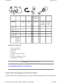
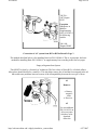
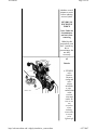
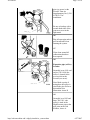
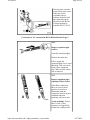
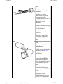
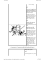
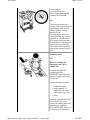
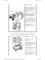
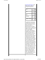
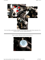
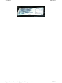
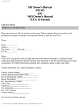
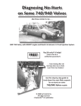
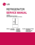
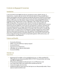
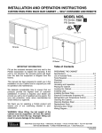
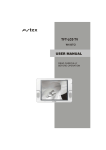
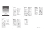
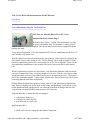
ACconvert
Page 1 of 18
VOLVO AC R134 refit kit instructions for the 700 series
FAQ Home
Volvo Maintenance FAQ for 7xx/9xx/90 Cars
CFC-Free A/C Retrofit Kit for Pre-1993 Volvos
Introduction; Kit Contents: Page 1
Written by Dave Urban. Caution: This information is giving
for purely information only. No Warrantee is either given or
implied. Only people who have the correct equipment should
perform this task.
Years ahead of legislation, Volvo first introduced CFC-free air conditioning on all of its U.S.
and Canadian 1993 model cars.
With the public's increasing concern about the environment, Volvo released a retrofit kit for
older model Volvos in the spring of 1993. The kit allowed Volvos with existing R12 freon
based air conditioning systems to be converted to use a CFC-free refrigerant. Volvo was the
first automobile manufacturer in the world to offer such a conversion kit for older model
cars.
When I purchased my kit from my local dealer, I was shocked to find that it did not include
any type of instructions. They were kind enough to fax it to me. This is a web version of the
instructions that I received. I have added some of my own comments in italics. This is not a
job for the weekend mechanic . It does require special tools. Some of those tools can be used
at the shop then the work done at the house.
[Editor] When the instructions mention "torque joint to 12 Nm" this means to tighten until
snug. Don't overtighten: the seal is made by the o-ring, not the threads. Lubricate the o-ring
before installation with compressor oil; use a backup wrench on all fittings; and test with
soap solution (which will bubble in the presence of a leak) after
Supplementary Kit 1, mainly for cars not equipped
z
z
z
with,factory-fitted valve,
with pipes or where pipe has
been removed as a service fix
Supplementary Kit 2
z
Shaft seal kit for cars equipped with Sandan Compressor
http://oak.cats.ohiou.edu/~ridgely/retrokit/ac_convert.htm
6/27/2007
ACconvert
Page 2 of 18
Replaces
91456640
740/940
9145660- 91456618
6
91340323
9134344- 91343452 (SD9 (SD510/508)
709)
B23F
-
*
-
-
-
-
B230F
-92
*
-
*
-
-
D24T
-87
*
-
*
*
-
B234F
-
*
-
*
-
-
B230FT
940SE
USA
Turbo
1991
-
*
-
-
-
The basic kit comes with
z
z
z
z
z
z
z
z
New receiver/Dryer
R134a filler valve
Ester Oil
O-rings
R12 Filler permanent Caps
Circlip
Kit costs: 9145660-8 - $57.00
Supplement #1 - $30.00
Go to: Page 1 2 3 4 5 6 7 8 9 10
Volvo Maintenance FAQ for 7xx/9xx/90 Cars
Contents of basic and supplementary kits from R12 to R134a
Note that both the basic and supplementary kits can have different part numbers. Some of the basic kits
http://oak.cats.ohiou.edu/~ridgely/retrokit/ac_convert.htm
6/27/2007
ACconvert
Page 3 of 18
may have different supplementary kits.
Use these pages a guidelines for the conversion of the A/C system
Basic Kit
9145660-8
The illustration
shows a car with
the pipe runs and
the factory filling
valve installed.
My car did not
have this and
need Sup kit#1.
The basic kit has
the new quick
release valve that
the R134a uses.
This illustration
shows a car not
equipped with
the factory filling
valve. This can
also occur if the
A/C was
installed as an
accessory.
In this case a
Supplementary
kit, PN 91340323 is also required
which replaces
the pipe shown
in the upper part
of the
illustration.
Exception 1:
Requires in
addition
Supplementary
kit (2) PN
9134344-2 for
following models
http://oak.cats.ohiou.edu/~ridgely/retrokit/ac_convert.htm
6/27/2007
ACconvert
Page 4 of 18
740/760 1987 Engine
D24T
Exception
2:Requires in
addition
Supplementary
kit(2) 9134345-9
for following
models:
780 1988Engine B280F
Conversion of A/C system form R12 to R134a Retrofit: Page 3
The method described below is for installing Basic kit PN 9145660-8. This is, in principle, the basic
method for installing Basic PN 9145661-1 or supplementary kits according to the first two pages.
Empty refrigerant from System
This MUST be done by a licensed AC technician. The free release of freon R12 is a federal offense.
Most places should do this for a small fee. This also helps remove the oil and the freon trapped in the oil
that could cause problems later on because of the incompatibility between the two type of freon.
A1
Remove:
z
z
Battery
negative
cable
Receiver
A2
Use rust inhibitor
PN 1161422-9 on
all screw joints
which are to be
detached
Allow the
http://oak.cats.ohiou.edu/~ridgely/retrokit/ac_convert.htm
6/27/2007
ACconvert
Page 5 of 18
inhibitor several
minutes to work
before undoing
screwed joints.
NEVER USE
EXCESSIVE
FORCE
Note: Under no
circumstances
use heat when
removing
I didn't do this
step and all went
fine. I would say
this is
precautionary but
not fully
necessary
A3
Detach:
z
http://oak.cats.ohiou.edu/~ridgely/retrokit/ac_convert.htm
ETF/KRU
valve
bracket.
Remove
circlip and
valve
(where
installed)
z pipe
connections
at the
receiver
inlet and
outlet. Be
sure to use
two
wrenches
when
undoing
connections
so not to
twist
lightweight
6/27/2007
ACconvert
Page 6 of 18
z
metal.
z the
pressostat
connector.
Remove
pressostat:
this will be
reused.
This is the
low
pressure
cutoff
switch. If
defective
you can
purchase
one at the
local parts
store for
about $12.
Existing O
rings (note
sizes)
Replace
with new
rings from
kit on new
equipment.
A4
Remove screws
holding the
receiver clamp
A5
Lift out Receiver
Conversion of A/C system form R12 to R134a Retrofit: Page 4
Remark:On older cars or
cars where the A/C
system was installed as
an accessory, there is no
EFT/KRU valve
In this case remove the
http://oak.cats.ohiou.edu/~ridgely/retrokit/ac_convert.htm
6/27/2007
ACconvert
Page 7 of 18
pipe (see arrow) at the
firewall. Then use
Supplementary kit (1) PN
9134032-3 for
installation.
Be sure to backup with a
wrench both sides of the
joint as no to twist the
light metal.
A6
Plug all open pipe ends to
prevent moisture from
entering the system.
A7
Wipe clean around all
connections that have
been opened.
A8
Expansion pipe (orifice)
location:
On model years 1991 and
earlier (780 -1990) the
orifice is located in the
receiver inlet at the
firewall (see arrow).
Note: Make a point of
noting how the orifice is
sited in the pipe. Refer to
this and the next
illustration. Arrow B
A9
On model year 1992 and
later (780 1991-) the
orifice is sited in the
High-Pressure pipe at the
pipe joint on the side
member, Arrow A
http://oak.cats.ohiou.edu/~ridgely/retrokit/ac_convert.htm
6/27/2007
ACconvert
Page 8 of 18
Note: In some cases the
work will be made easier
if the pipe for the
evaporator inlet is
removed at the firewall
(the right side pipe as
shown at Arrow B).The
O ring must then be
replaced PN 3537503-9
Conversion of A/C system form R12 to R134a Retrofit: Page 5
A10
Remove expansion pipe
(orifice)
Clean the joint thoroughly
Remove the union nut
Pull or wiggle the
expansion pipe out ( it is not
threaded). Take care not to
break off the expansion
pipe. Make sure the whole
unit is removed.
A11
Inspect expansion pipes
(opening's) filter section
If the filter is choked or
there are a lot of metal
particles in it (refer to
illustration) then the
compressor may be in poor
condition and need
replacing with a new unit.
A rule of thumb: If more
than 3 of the 5 filter
sections are clogged (Fig.
B) then the compressor oil
http://oak.cats.ohiou.edu/~ridgely/retrokit/ac_convert.htm
6/27/2007
ACconvert
Page 9 of 18
should be examined. If the
compressor oil is black and
heavily contaminated, or if
the compressor is dry, then
replace the compressor with
a new unit. Fig A shows an
orifice that is normal.
After inspection the old
orifice should be scrapped.
The conversion kit contains
a new one.
A12
If the compressor must be
replaced:
The new compressor unit as
a replacement part is filled
with mineral oil. Empty the
oil and replace with ester oil
(200 ml 6.76 fl oz) form the
conversion kit
Warning! Do not fill
Receiver with oil if
replacing the compressor.
Only fill the compressor
using the filler plug not
through the inlet or outlet
connections.
Note! The O rings on the
compressor inlet and
outlet must always be
replaced with new ones
These Rings are not
included in the kits and
must be orded separatlly
For compressor replacement
refer to the Service Manual
Section 8 (82-88) Body
Fittings, Interior, Climate
Units 740, 760 1982-19...
Conversion of A/C system form R12 to R134a Retrofit: Page 6
http://oak.cats.ohiou.edu/~ridgely/retrokit/ac_convert.htm
6/27/2007
ACconvert
Page 10 of 18
A13
Install expansion pip
(orifice).
Install a new yellow
lubricated O ring on the
new expansion pipe.
Compare size on the new O
ring with the old one so
they are the correct
dimension.
Install a lubricated O ring in
the pipe joint at the firewall
(or side member).
Install expansion pipe
(orifice).
Tighten the joint to the
evaporator (or the side
member) to 12 Nm (9 ft.
lbs).
A14
Top up the oil level in the
new receiver
Fill the receiver through the
inlet side with ester oil
supplied in the conversion
kit (200ml).
Note: If the compressor has
been replaced and filled
with ester oil in previous
steps, no additional ester oil
is needed in the receiver.
A15
Remarks: On older cars
without pipes for ETF/KRU
valve;
Install pipes from
Supplementary kit (1) PN
9134032-3 Finger tighten
http://oak.cats.ohiou.edu/~ridgely/retrokit/ac_convert.htm
6/27/2007
ACconvert
Page 11 of 18
against the receiver. Use
lubricated O rings. Connect
filling pipe (U pipe) using a
new lubricated O-ring
Conversion of A/C system form R12 to R134a Retrofit: Page 7
A15
Install the following:
z
z
z
Receiver in the Car
new lubricated Orings at the joint
between the
evaporator and at
the receiver outlet.
pipe to evaporator
and at the outlet.
Tighten by hand
A16
Tightening an torques:
z
z
z
z
http://oak.cats.ohiou.edu/~ridgely/retrokit/ac_convert.htm
the pipe between
the evaporator and
receiver. 27 Nm
(20ft lbs) at the
evaproator and 45
Nm (33 ft lbs) at
the Receiver
the pipe at the
receiver outlet with
45 Nm(33 ft lbs)
fillter pipe (Upipe)
with 16 Nm(12 ft
lbs)
screws on the
6/27/2007
ACconvert
Page 12 of 18
receiver clamp
A17
Use a new O-ring for the
old pressostat,(lubricate
with ester oil) and install
it on the receiver
Compar size of the new
O-ring with the old one to
ensure correst dimension.
Tighten the pressostat
with 3.5 Nm(31 in. lb)
A18
Connect the connector
to the pressostat
A19
Install the new SAE
Filler valve for R134a
Alternative 1: Use a new
yellow lubricated O-ring
and install on the filler
pipe (U pipe). Insatll SAE
filler valve. Tighten with
15 NM (12 ft. lbs)
Alternative 2: Use a new
yellow lubricated O-ring.
Install on the filler pipe
(U pipe). Insatll SAE
filler valve and circlip
(included in basic kit).
Tighten with 15 NM (12
ft. lbs)
Conversion of A/C system from R12 to R134a Retrofit: Page 8
Inspect A/C System
A20
Vacuum pump the A/C system
http://oak.cats.ohiou.edu/~ridgely/retrokit/ac_convert.htm
6/27/2007
ACconvert
Page 13 of 18
Connect R134a
recycling/filling unit.
Start vacuum pumping and
continue for at least 50
min.
Check that system keeps a
vacuum. The vacuum must not
sink during a 4 min period.
(This is with the vacuum
turned off) The
recycling/filling unit is not
required for this step. I used a
standard AC vacuum from a
R12 system. and connected it
to the other R12 charging port
opposite the pressostat (See
arrow in the bottom picture)
and ran the vacuum for the 50
min.
Finalizing work
A21
While evacuating, the
following work can be
carried out:
Complete the light blue
rectangular R134a
RETROFIT label before the
protecteive paper and carbon
is removed
Using ball-point pen, note:
z
z
z
technician intials
dealer number, if
applicable ( or repar
shop name, city, state)
Date
Carefully clean off the old r12
decal on the body work,
remove the carbon paper and
stick the new, light-blue
R134a RETROFIT lable over
it. Make sure the old label is
http://oak.cats.ohiou.edu/~ridgely/retrokit/ac_convert.htm
6/27/2007
ACconvert
Page 14 of 18
completely covered.
Using mineral spirits, clean
top of accumulator, then stick
the round R134a RETROFIT
decal on the receiver.
A22
Install the caps (included in
kit) in the service valves
which are no longer used.
Two on the compressor (in
sertain cases there are none on
th ecompressor) and one on
the receiver (see illustration
below)
Use locking fluid PN
1161351-0 or equivalent on
the caps.
Conversion of A/C system from R12 to R134a Retrofit: Page 9
A23
Refilling system with
refrigerant
On completion of vacuum
pumping, fill system with
max. 200 grams (0.44 lbs)
refrigerant R134a
Leakage testing after filling.
Use leakage detector.
Repair any leaks.
When no leakage is detected
fill with remainder of
refrigerant R134a to the
http://oak.cats.ohiou.edu/~ridgely/retrokit/ac_convert.htm
6/27/2007
ACconvert
Page 15 of 18
amount stated below. (the
link refers to a table of
refrigerant capacities)
740
1990
760
1987
780
1991
740/940
9192
940SE/760/960 8892
2.4
lb
2.4
lb
2.4
lb
2.1
lb
2.0
lb
I applied the small amount
of freon from a filler hose
that I purchased at a local
parts store where I
purchased the freon cans.
One end screws onto the can
and the other snaps onto the
filler cap installed
previously. Hold the can
upright so gas, not liquid, is
sucked into the system. I
then opened the valve and
let the vacuum suck the
initial freon into the system
and then the can provided
enough pressure to trigger
the pressostat switch to turn
on the compressor. I started
the car and turned the A/C
system on to max cool and
raised the idle and made the
compressor suck the freon
out of the can. I have a 88
740 which requires 2.4 lb or
38 oz. The cans are 12 oz. I
put in 36 oz and saved the
other can for a spare. Once
freon is added check for
proper cooling, and your
done. The remainder is if
you could pump the correct
amount in the system.
http://oak.cats.ohiou.edu/~ridgely/retrokit/ac_convert.htm
6/27/2007
ACconvert
Page 16 of 18
Verify Functions
A24
Start:
z
z
Engine
A/C System
Check that:
z
z
Compressor starts and
operates normally
without unusual
noise
In car air is cooled.
Stop engine
Check for leakage with
leakage detector Repair and
leaks indicated.
This is my 1988 745 Volvo which has had the AC RETROFIT
Here are some pictures of the retrofitted parts. Looks about the same.
http://oak.cats.ohiou.edu/~ridgely/retrokit/ac_convert.htm
6/27/2007
ACconvert
Page 17 of 18
Here is the filler cap and the filler cap opened. Notice that the filler is a quick release connection. You
can also see the U joint from supplementary kit (1)
Here is a picture of the notice stickers you put on the car.
http://oak.cats.ohiou.edu/~ridgely/retrokit/ac_convert.htm
6/27/2007
ACconvert
http://oak.cats.ohiou.edu/~ridgely/retrokit/ac_convert.htm
Page 18 of 18
6/27/2007