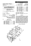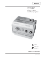
1
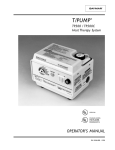
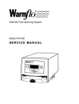
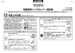
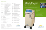
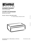
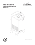
®
®
T/PUMP
TP500 / TP500C
Heat Therapy System
LISTED 304L
STANDARD (NORME)
C22.2 NO. 125 RISK
CLASS (CATEGORIE
DE RISQUES) NO. 2G
SERVICE MANUAL
P/N 11950-000 9/03
CONTENTS
SERVICE MANUAL
TP500/TP500C T/PUMP
BEFORE YOU BEGIN . . .
CONTENTS
SafetyPrecautions ..................... 1
Introduction ......................... 2
Features ............................ 3
Specifications ........................ 4
OperatingInstructions .................. 5
Storage/Cleaning ...................... 7
Theory of Operation ................... 8
FunctionalCheckandSafetyInspeciton ....... 10
InspectionForm ...................... 15
Disassembly/Reassembly ................. 16
Calibration .......................... 19
Troubleshooting ...................... 21
ReplacementParts ..................... 27
Warranties .......................... 30
ILLUSTRATIONS
1
2
3
4
5
6
7
8
9
10
11
T/Pump® Heat Therapy System ........ 2
Features/Specifications .............. 3
Clik-Tite® Connectors .............. 5
Colder-styleConnectors ............ 5
T/Pump Components .............. 9
Motor ........................ 11
TPC1 Test Covers ................ 22
Functional Check Test Diagram ....... 23
Circuit Diagram for T/Pump .......... 24
Circuit Diagram for TPC1 Test Cover ... 25
Exploded View of T/Pump ........... 26
Read and understand this
T/PUMP SERVICE MANUAL and all
PRECAUTIONS (see page 1) prior to
servicing the T/Pump.
Thepurposeofthismanualistoprovideoperation,
service, and repair information for GAYMAR heat
therapypumps.
RECEIVING INSPECTION
Checktheshippingcartonfordamageimmediately
uponreceipt.Ifpackagedamageisdiscovered,the
deviceshouldbeunpackedwiththecarrier'sagent
present. Any claims for shortage or damage must be
filedwiththedeliveringcarrierbythepurchaser.Do
not return pumps damaged in shipment to GAYMAR
withoutcontactingourTechnicalService
Department for advice (see phone numbers below).
If damaged goods are returned to GAYMAR without
notifyingthecarrier,GAYMARwillassumethe
repairswillbemadeatthecustomer'sexpense.
TO RETURN PUMPS TO FACTORY
FOR REPAIR OR EXCHANGE
Merchandise returned to GAYMAR must be
accompanied by a Return Goods Number (RG#),
issued by GAYMAR, authorizing goods to be
returned.CallCustomerServiceorTechnical
Serviceat
(716)662-2551
1 800 828-7341
Advisemodel,serialnumber,andnatureofproblem.
You will be given a Return Goods Number (RG#).
The serial number is on the back of the T/Pump
(seefigure2,p.3).
T/PUMP, T/PAD, Mul•T•Pad, Clik-Tite, and Gaymar are registered trademarks of Gaymar Industries, Inc. U. S. PATENT 4,068,870
©2001.GaymarIndustries,Inc.Allrightsreserved. www.gaymar.com
SERVICE MANUAL
TP500/TP500C T/PUMP
SAFETY PRECAUTIONS
DANGER
• Risk of explosion. Do not use in the presence of flammable
anesthetics.
• Risk of electric shock.Disconnect power before servicing
the T/Pump.
WARNING
• This device pumps warmed water through a pad. Set pad
temperatureonlyasprescribedbyandundertheguidanceofa
physician.Monitorthepatient'stemperatureandskincondition
every20minutesorasdirectedbyaphysician.Failureto
adhere to these warnings could result in patient injury.
ThefollowingGroups/Conditionsrequireadditionalsurveillance:
Group/Condition at risk
Potential injury
Pediatric patients
Hyperthermia/
hypothermia
Patients with impaired circulation
Ischemia
Areas of application are under pressure
Ischemia
In combination with topical solutions whose toxicity Chemical
may be affected by the application of heat
injury
In combination with other heat sources
Thermal injury
• Onlyqualifiedmedicalservicepersonnelshouldrepairthe
T/Pump. Improper repair may result in death or
serious injury, equipment damage, or malfunction.
• Always perform the FUNCTIONAL CHECK AND SAFETY
INSPECTION(pp.10-14)aftermakingrepairsandbefore
returning the T/Pump to patient use. Document your
findings on the INSPECTION FORM (p. 15). Improper
repair may result in death or serious injury,
equipment damage, or malfunction.
CAUTION
• Do not perform any powered tests with the reservoir empty.
Damage to the T/Pump may result.
1
SERVICE MANUAL
TP500/TP500C T/PUMP
INTRODUCTION
SinglePad
MultiplePads
Figure 1—T/Pump Heat Therapy System
Heattherapyiseffectiveinthedilationofbloodvessels,therebyincreasing
thebloodflowtotheheatedarea.Heattherapyhasavarietyofuses,the
most common being treatment of aches and pains in joints and muscles.
The GAYMAR T/Pump® Heat Therapy System provides a means of
applyingheattherapybysupplyingtemperature-controlledwaterthrougha
connector hose to a Gaymar T/Pad®. The hose is terminated in easy-to-use
Clik-Tite® orColder-styleconnectors.
TheT/Padprovidestheinterfacefordeliveringtheheattherapy.The
uniquebuttondesignallowswatertoflowandprovidestrouble-free
operation when the pad is folded. This reduces the number of pads your
facilitymustkeepininventory.Thepadsareappliedtothepartofthe
bodyrequiringheattherapy,andthecirculatingwatermaintainsthepadat
thesetpointtemperature.Thetemperaturesetpointiskey-operatedto
preventtampering.
The T/Pads can be interconnected (on model TP500 only) to provide
therapy to more than one body site at a time.
2
SERVICE MANUAL
TP500/TP500C T/PUMP
FEATURES
Figure2—T/PumpFeatures
FEATURES
Attached Hose
10 ft (305 cm) dual hose. Connectors allow pads to be
connectedtothepump(seefigs.3and4,p.5).
Tip-over
Switch
Turnsheateroffifpumpistipped.
NOTE: This does not activate the OVER TEMP light.
HospitalID
Label
A label is provided on the back of the T/Pump for your
convenience.Useafelttiporballpointpentoaddany
requiredhospitalidentification.
OVER TEMP
Light
Indicatesthepumpandheaterhavebeenturnedoff.
ThislightisactivatedbythetwoOVERTEMPsafety
thermostats. Refer to the TROUBLESHOOTING section.
CircuitBreaker
Whenthecircuitbreakertrips,thesmallbuttonin
thecenterwillextend1/4",exposingawhiteband.
Refer to the TROUBLESHOOTING section.
OVER TEMP
Safety
Thermostats
Eitheroftwolimitthermostatswillshutoffpumpandheater
if the high temperature limit is exceeded. TheOVER TEMP
lightwillglow.RefertotheTROUBLESHOOTINGsection.
3
SERVICE MANUAL
TP500/TP500C T/PUMP
SPECIFICATIONS
SPECIFICATIONS
Size(approx.)
8-1/8"x5-5/8"x6-1/4"
(20.6 cm x 14.3 cm x 15.9 cm)
Weight (empty)
5lbs,2oz(2.3kg)
Reservoircapacity
51 oz (1500 ml) maximum
Flowrate
9 gph (34 lph) minimum with pad attached
Ambientoperating
temperatures
60°F to 90°F (15.6°C to 32.2°C)
Storagetemperatures
(empty)
-30°Fto160°F(-34.4°Cto71.1°C)
Temperaturesetpoint 85°F to 107°F (29.4°C to 41.7°C)
range
Averageoperating
temperatureaccuracy
±2°Fat107°Fsetting
Power cord
18 AWG, 3 conductor, 9 ft (274 cm), Type SJT
with molded,hospitalgradeplug
Circuitbreaker
3 amperes
1stbackuplimit
thermostat
(manifoldmounted)
Bimetallic(trippointfixed)
110°F to 117°F (43.3°C to 47.2°C)
2ndbackuplimit
thermostat
(wellmounted)
Bimetallic(trippointfixed)
110°F to 122°F (43.3°C to 50°C)
Currentleakage
100 microamperes maximum
Groundresistance
0.5 ohm maximum
Electricalrequirements
Voltage (VAC)
Frequency(Hz)
Current(amps)
Powerreq'd(watts)
Safetyapprovals
4
120
60
1.8
200
Tested to UL 544 and CSA C22.2, No. 125
SERVICE MANUAL
TP500/TP500C T/PUMP
OPERATING INSTRUCTIONS
T/Pumps are supplied with one of two types of hose connectors:
TP500 T/Pumps have Clik-Tite® connectors;
TP500C T/Pumps have Colder-style connectors.
CLIK-TITE® CONNECTORS
(on TP500):
ToattachClik-Titeconnectorsfromhosetopad:
1.
Insertmalefittingsintofemalefittingswith
atwistingmotion(figs.3Aand3B).
2.
Whenfittingsarefullyinserted,snaplocking
ringintoplace(figs.3Cand3D).
3.
Todisconnect,simplyreversetheprocedure.
4.
To open or close the hose pinch clamps:
•
Open the clamp by pushing the serrated
end(fig.3E).
•
Close the clamp by pressing the clamp
together(fig.3F).
NOTE: Refer to figure 1 (p. 2) and
item 9 (p. 6) when connecting
multiple pads.
Figure3A–3D—Clik-Tite® Connectors
3E
3F
Figure 3E–3F—Hose Pinch Clamps
COLDER-STYLE
(on TP500C):
1.
2.
CONNECTORS
ToattachColder-styleconnectorstoapad,
push the male coupling onto the female coupling.Whenyouhearanaudible“click”,the
connectorsarejoined(fig.4A).
4A
TodisconnectColder-styleconnectors,press
down on the thumb tab of the female coupling.
Thecouplingswillpartiallydisconnect.Pullthe
malecouplingoutfullytodisconnect(fig.4B).
4B
Figure 4—Colder-style Connectors
5
OPERATING INSTRUCTIONS
START-UP PROCEDURE
SERVICE MANUAL
TP500/TP500C T/PUMP
1. Beforefilling,alwaysattachaT/PadtotheT/Pumpconnectorhose(see
figs.3and4,p.5).Unkinkpadandhose.Openhoseclamps.
2. Open the fill cap on top of the pump. Fill the pump with room
temperature(i.e.,nothot)distilledwatertotheoperatinglevel
indicatedonthesideofthepump.
NOTE: Using tap water will decrease the life of the pump.
3. Inserttemperaturesettingkey.Settemperatureasprescribedbythe
physician.Removekeytopreventtampering.
4. Plugthepumpintoaproperlygroundedoutlet.
5. Turn on the power switch. The selected water temperature will be
reachedinapproximately20minutes.
6. Ifthewaterleveldropsbelowtheoperatinglevel,addwater.Donot
overfill. Overfilling can result in reduced pump motor life.
7. ApplyT/Padtothepatient.FollowT/Padinstructions.
8. Forspecifiedperformance,keepthepumpatorabovethelevelofthe
pad.
9. Ifthepumpisplacedbelowthepad(s),waterwilldrainintothepump
whenitisshutoff.Ifthepumphasbeenoverfilledorifmultiplepads
areconnected,excesswatercanleakoutontothefloororcause
reducedmotorlife.
SHUTDOWN
PROCEDURE
1. Turnoffpumpbeforedisconnectingpad.Closeallhoseclamps.
Topreventwaterspillage,alwaysdisconnectpadfrompumpwith
connectorsraisedabovethelevelofthepadandpump.
2. ConnecttheT/PadClik-Titeconnectorstogether,whereapplicable.
3. Connect the ends of the T/Pump connector hose together
(TP500only).
6
SERVICE MANUAL
TP500/TP500C T/PUMP
STORAGE / CLEANING
Storage (Short term)
Disconnect pad. Connect ends of the connector hoses together,
whereapplicable.Openhoseclamps.Leavewaterinthereservoir.
Topreventhosekinks,coilthehoseratherthanfoldingit.Fastenthehose
andcordwithstrap.
Storage (Long term)
Connect pad. Open hose clamps. Add 1/4 ounce GAYMAR MTA33
germicidalorequivalenttowateralreadyinreservoir.Runfortwo(2)
minutes. Drain pump. Close hose clamps. Disconnect pad. To prevent hose
kinks,coilthehoseratherthanfoldingit.Fastenthehoseandcordwith
strapandstorepump.
Draining
Unplug the power cord. Disconnect the pad or hoses from one another,
keepinghosesatorabovetheleveloftheT/Pump.Removethefillcapand
inverttheT/Pumpoverasink.Whenallfluidhasdrainedfromthehoses
andreservoir,replacethefillcapandconnectthehosestogether,where
applicable.
Cleaning
Unplug the power cord.
Tocleantheexternalsurfaces,useanon-abrasivecleaningsolution(such
as warm, soapy water) and a damp cloth.
Tocleanthefluidsystem,drainthepump.Fillthereservoirtotheoperating level indicated on the side of the pump. Add 1/4 ounce GAYMAR
catalogMTA33germicidalorequivalent.Setthetemperatureindicatorto
itslowestsetting(fullycounterclockwise).StarttheT/Pumpandcirculate
thesolutionforonehour.Drainthesolutionandrefillthepumpwith
distilledwater.Usingdistilledwaterretardsalgaegrowthandmineral
buildup.
Change the distilled water monthly or more often depending upon use.
Pads/Accessories
For best results use only GAYMAR T/Pads® or Mul•T•Pads®. The unique
buttondesignallowswatertoflowandprovidestroublefreeoperation
whenthepadisfolded.Thisreducesthenumberofdifferentsizesofpads
yourfacilitymustkeepininventory.TheT/Padscanbeinterconnected(on
model TP500 only) to provide therapy to more than one body site at a
time(seefig.1,p.2).Forabrochurelistingthevariouspads,contactthe
GAYMAR Customer Service Department (see inside cover for telephone
numbers).
An optional bed bracket (model TP20A) is available to mount the T/Pump
on the footboard of a bed.
7
THEORY OF OPERATION
WATER TEMPERATURE
CONTROL
SERVICE MANUAL
TP500/TP500C T/PUMP
Therearefourdevicesthatcontroltheoperationoftheheaterinthe
GAYMAR T/Pump:
• Thetemperaturecontrolleristhermistoractuated (fig.5,item1,p.9).
Thiscontrollerisadjustableoveratemperaturerangeof85°Fto107°F
(29.4°Cto41.7°C).Thedesiredwatertemperatureissetwithaspecial
removablekey(fig.5,item7).Topreventunauthorizedtemperature
settingchanges,removethekeyafterthetemperaturehasbeenset.
• Themanifoldbackuplimitthermostat(fig.5,item9)ismountedonthe
brassmanifoldblock(fig.5,item8).Thisthermostatsenseswater
temperature flowing to the pad and will shut off the pump and heater
andactivatethe OVERTEMP lightifthewatertemperatureexceeds
specificlimits.Thepurposeofthemanifoldbackuplimitthermostatisto
prevent the pump from providing water at too high a temperature to
thepad.
• Thewellbackuplimitthermostat(fig.5,item5)ismountedonthebrass
plate(fig.5,item11)thatextendsalongandundertheheater(fig.5,
item4)nearthebottomofthereservoir.Thisthermostatsenseswater
temperatureinthereservoirandwillshutoffthepumpandheaterand
activatetheOVERTEMPlightifthereservoirtemperatureexceeds
specificlimits.Thepurposeofthewellbackuplimitthermostatisto
both prevent the pump from providing water at too high a temperature
to the pad and to protect the pump from high temperature damage due
toalowwaterlevel.
• Thetip-overswitch(fig.5,item2;seealsofig.12,item64,p.27)is
mounted on the PC board. This mercury-type switch will shut off the
heaterifthepumpistippedmorethan45°fromtheverticalposition.
NOTE: The tip-over switch does not shut off the pump
motor or activate the OVER TEMP light.
FLUID SYSTEM
Thepump(fig.5,item12)isasumpconfigurationdrivenbyanimpedance
protected,shadedpoleACmotor(fig.5,item6).
Thereturnhosefitting(fig.5,item10)ismachinedinternallytoactasan
orifice.Thismaintainsabackpressureinthepadtomakeitresistantto
flowrestrictions.
8
SERVICE MANUAL
TP500/TP500C T/PUMP
FIGURE
5—T/PUMP
T/PUMP
COMPONENTS
COMPONENTS
TOP
(wireharnessremovedforclarity)
BOTTOM
9
FUNCTIONAL
CHECK
FUNCTIONAL CHECK &
SAFETY INSPECTION
SERVICE MANUAL
TP500/TP500C T/PUMP
Thissectionisdesignedtoprovideacompletecheckofallpumpparameters.Theorderoftestsshouldbefollowedsothatthefunctionaltesting
canbecompletedintheleastpossibletime.
Follow the FUNCTIONAL CHECK AND SAFETY INSPECTION carefully, paying
particularattentiontotestsetups.Anydeviationfromthesetups,
procedures,ortestequipmentmayresultinincorrectormisleadingresults.
Beforemakinganyrepairs,besuretorecheckyourtestsetup,procedure,
andtestequipment.
DANGER
Risk of electric shock. Disconnect power before servicing the
T/Pump.
WARNING
• Onlyqualifiedmedicalservicepersonnelshouldrepairthe
T/Pump. Improper repair may result in death or serious
injury, equipment damage, or malfunction.
• Always perform the FUNCTIONAL CHECK AND SAFETY INSPECTION
aftermakingrepairsandbeforereturningtheT/Pumptopatientuse.
Document your findings on theINSPECTION FORM (p. 15).
Improper repair may result in death or serious injury,
equipment damage, or malfunction.
CAUTION
Do not perform any powered tests with the reservoir empty.
Damage to the T/Pump may result.
INTERVAL
Toassuretheoptimumperformance,dependabilityandsafety,thefollowing
shouldbeperformedonceperyear(orasspecifiedinthefacility's
preventivemaintenanceprogram)andaftermakingrepairs.
REQUIRED TOOLS
TPT9 ---------- GAYMAR Flow and Temperature Tester
[When testing TP500C, use also an
Adaptor Hose Assembly, P/N 77926-000)
TFC1 ---------- Thermometer, 30°F to 125°F (-2°C to 52°C), 1°C
accuracy,12"long,3"immersion(e.g.,Brooklyn
Thermometer #73544 or equivalent, Brooklyn
Thermometer Co., Farmingdale, NY 11735)
T/Pad --------- Any GAYMAR “12” or “22” series T/Pad;
or, TP612 or TP622 pad as applicable
TPC1 --------- GAYMAR T/Pump Test Cover
GroundResistanceTester
Current Leakage Meter
DistilledWater --- 2liters(approximate)
SyntheticOil ----- Anderol #465 (GAYMAR P/N 77137-000)
INSPECTION FORM - (p.15)
10
SERVICE MANUAL
TP500/TP500C T/PUMP
PHYSICAL CONDITION
CHECK
FUNCTIONAL
CHECK
1. Examinethelinecordalongitsentirelengthforphysicaldamage,such
ascutsorcrackedinsulation.Adamagedlinecordshouldbereplaced
ratherthanrepaired.Checkthequalityofthestrainreliefsatbothends
ofthelinecord.
2. Examinetheplugonthelinecordtobesureitisingoodcondition.If
unit has non-molded type plug, open plug and check for wire breakage
andlooseterminalscrew(s).Ifdefective,replacewithahospitalgrade
plug.Torqueterminalscrew(s)andoutsidehousingscrewsto12in.-lbs.
3. Operateswitchesandcontrolsettingsatallpositions.Ifdefective,
replace.
4. Visuallyinspectpump.Checkforcrackedordamagedplasticparts.
Be sure unit is unplugged. Remove retainer cap. Remove four (4)
screwsholdingcoverandremovecover.(Besurenottolosefillneck
gasket.)Performvisualinspectionofallinternalparts.Removeany
accumulated dirt with a vacuum cleaner or compressed air hose. Leave
coveroffforbalanceofinspection.
5. Checkconnectorsforcracks,missingOrings,orotherdamage.
Replaceconnectorsifnecessary.
MOTOR
LUBRICATION
1. Locatethemotormanufacturer'sIDonthetopbearinghousing.
IfthepumpmotorisbyJakel,nooilingisrequired.Ifthepumpmotor
isbyUppco,proceedwiththefollowingoilinginstructions.
2. Oil the pump motor every 6 months with Anderol #465 (GAYMAR
P/N 77137-000) or equivalent to extend the life of the T/Pump motor.
Anderol#465isasyntheticoil.Donotuseapetroleum-basedoilsince
itwillleavearesidueasitbreaksdown,causingthemotortoseize.
Addfour(4)dropsofoiltotheventholeinthebearinghousingofthe
motorlocatedbelowthefan.Usingamicrooiler,applyasimilar
amounttothelowerbearingatthelocationindicatedinfigure6.
NOTE: Early versions of
the pump motor have an
oiler tube which does
noteffectivelydistribute
oil to the lower bearing.
Do not use the oiler
tube to apply oil to the
lower bearing. Use a
micro oiler to apply oil
directly to the locations
shown in figure 6.
Figure 6—PUMP MOTOR
11
FUNCTIONAL
SERVICE MANUAL
TP500/TP500C T/PUMP
CHECK
TPC1 TEST COVER
INSTALLATION
1. When connecting the test cover, do not remove any wiring connectionsintheT/Pump.Simplyclipthetestcoveralligatorclipsonto
terminalswiththesamecolorwire.
2. ConnectTPC1testcover(seefig.7A/7B,p.22and10A/10B,p.25).
Always match the color of TPC1 wiring connections to the color of
T/Pumpwiring.Besuretokeepwiresawayfromfan.Installtestcover.
Besuretopushcoverontightly.Itisnotnecessarytoinstallscrews.
3. Connect pump with test cover, pad, TPT9 flow/temp tester, and
adaptorhoseassemblyifrequired(seefig.8,p.23).BesuretheTPT9is
connectedtothesupplysideoftheT/Pump,beforethepad.
4. Fillunitwithroomtemperaturedistilledwaterandreplacefillcap.
Connectpad.Placepadonaninsulatingmaterial(e.g.,clothortowel).
5. SetbothtestcoverswitchestotheOPENposition.
GROUND
CHECK
RESISTANCE
DANGER
Risk of electric shock. Be sure unit is unplugged when performing
thegroundresistancetest.
1. Use a ground resistance meter to measure the resistance between the
groundpinontheplugandthebrassmanifoldblock(fig.11,item47).
Contactisavailablethroughtheholewherethehosesconnecttothe
pump. This value should not be more than 0.5 ohm.
CURRENT LEAKAGE
CHECK
Itwillbeconvenienttocheckcurrentleakageatthispointsincetheunitis
fullandconnectedtoapad.
1. Measurethemaximumcurrentleakageinallcombinationsofheater
“ON” or “OFF” and power switch “ON” or “OFF.” Access to chassis
groundforcurrentleakagetestingisavailablethroughtheholewhere
thehoseconnectstothepump.Thehighestreadingistypicallyless
than 30 microamperes. The maximum allowable reading is 100
microamperes.Recordthehighestreading.
2. Disconnectleakagemetersetup.
TIP-OVER SWITCH CHECK
12
1. Checkthetip-overswitchatthispoint,sincethetestcoverison
andtheunitisfull.Settemperaturetomaximum(107°F)ondial.
Theheaterindicator(fig.7,p.22)willbeon.Tiptheunitapproximately45°.Iftheheaterindicatorgoesout,thetip-overswitchis
operating. Ifnot,repairorreplacethePCboard(p.17).Record
results.
SERVICE MANUAL
TP500/TP500C T/PUMP
FLOW RATE TEST
FUNCTIONAL
CHECK
1. Be sure the pad is flat and warm (approximately 107°F) and at the same
levelasthepump.TopofTPT9float(seefig.8,p.23)shouldreadat
least9gph.Recordreading.
NOTE: If flow is below 9 gph, refer to TROUBLESHOOTING section
(p.21).
OPERATING
TEMPERATURE TEST
1. Make sure temperature is set to maximum (107°F) on dial. Allow unit
tocometoasteadytemperature,approximatelythirty(30)minutes.
2. To ensure accurate temperature readings, add a small amount of water
to TPT9 well. Insert thermometer in TPT9 well.
3. Takereadingseverythirty(30)secondsforfive(5)minutesforatotal
often(10)readings.Theaverageofthesereadingsshouldbe107°F
±2°F.Recordtheaveragevalue.Iftheunitisoutofcalibration,referto
CALIBRATIONsection(p.19).
4. Do not let the pump cool down. Proceed directly to Backup Limit
ThermostatTest.
BACKUP LIMIT
THERMOSTAT TEST
1. With the pump operating properly at 107°F ±2°F, move the primary
shortingswitchtotheSHORTposition(seefig.7A/7B,p.22).Thiswill
short out the temperature controller and allow the pump to continue
heatingtothetrippointofthebackuplimitthermostat(s).
2. Carefullyobservetherisingtemperatureandrecordthehighest
reading. When a thermostat opens, the pump will turn off, the OVER
TEMPlightwillbelit,andtheHEATERINDICATORlightonthetest
coverwillturnoff.(IftheOVERTEMPlightdoesnotlightandathermostathastripped,replacethelight.)EithertheMANIFOLDorWELLlight
onthetestcoverwillbelitorbothlightswillbeoff,dependingon
whichthermostatshavetripped.
• Ifthemanifoldthermostatlightison,thenthemanifoldthermostat
has opened. The temperature recorded must be between 110°F to
117°F (43.3°C to 47.2°C). If the thermostat operates outside
its intended range, it must be replaced (see page 18).
Proceedtostep3.
• Ifthewellthermostatlightison,thenthewellthermostathas
opened. The temperature recorded must be between 110°F to 122°F
(43.3°C to 50°C). If the thermostat operates outside its
intended range, it must be replaced (see page 18). Proceed to
step3.
• Ifneitherlightison,thenboththermostatshaveopenedatthesame
temperature.Toconfirmthis,togglethethermostatshortingswitch
to the MANIFOLD position. (The MANIFOLD light should be on.)
Next,toggleswitchtotheWELLposition.(TheWELL lightshouldbe
on.) If either thermostat opens outside its intended range as
defined above, it must be replaced (see page 18). Proceed to
step4.
13
FUNCTIONAL
CHECK
SERVICE MANUAL
TP500/TP500C T/PUMP
3. Totesttheremainingthermostat,togglethelimitthermostatshorting
switchtothepositioncorrespondingtothenon-trippedthermostat.
(Thiswillshortoutthepreviouslyopenedthermostatandallowthe
unittocontinueheating.)Boththermostatindicatorlightsshouldbeoff
and the HEATER INDICATOR light should be on. Carefully observe the
risingtemperatureandrecordthehighestreading.Whenthewater
temperaturerisestothetrippointoftheremainingthermostat,the
OVERTEMPlightwillbeon,thepumpwillturnoff,theheaterindicator
lightwillturnoff,andtheappropriatethermostatlightwillbeon.
• Ifthemanifoldthermostatlightison,thenthemanifoldthermostat
has opened. The temperature recorded must be between 110°F to
117°F (43.3°C to 47.2°C). If the thermostat operates outside
its intended range, it must be replaced (see page 18).
• Ifthewellthermostatlightison,thenthewellthermostathas
opened. The temperature recorded must be between 110°F to
122°F (43.3°C to 50°C). If the thermostat operates outside
its intended range, it must be replaced (see page 18).
4. Unplug the unit, remove the test cover and proceed to LEAK TEST.
LEAK TEST
1. Immediately upon completion of Backup Limit Thermostat Test,
reinstallfillcaptightly.Putyourfingerovertheholeinthecapandtilt
unittowardyousothefrontisdown.Holdforthree(3)minutes.
2. Returntheunittouprightpositionandcarefullycheckinsideoftray
andreservoirtrayjointforleaks.Repeatprocessturningpumponback
face.Ifleakageisfound,refertotheDISASSEMBLY/REASSEMBLYsection
(pp.16-18),andcorrectproblem.
COVER AND FILL NECK
GASKET REINSTALLATION
Whenreinstallingcover,besurethefillneckgasket(fig.11,item6,p.26)
isinplace.Pushcoverdownastightlyaspossible.Holdinplacewhen
tighteningcoverscrews.
This completes the FUNCTIONAL CHECK procedure. Return
pumptoserviceifitisoperatingproperly,orproceedtothe
DISASSEMBLY/REASSEMBLYsectionpertainingtotheproblem(s).
14
SERVICE MANUAL
TP500/TP500C T/PUMP
INSPECTION FORM
Inspectionformsvaryfromhospitaltohospital.
Thefollowingsampleformisintendedasaguide
sothattheimportantparametersarerecorded.
T/Pump Functional Check and Safety Inspection Form
Date ______________
Model Number _____________________
Item
Serial Number __________________
Value
OK?
Action
Needed?
Action Taken
(check one)
1.
Inspect physical condition (line cord, plug, housing)
Inspect electrical compartment
(switches, fuse/circuit breaker)
Inspect hose connections and connectors
2.
Lubricate motor
3.
Connect TPC1 test cover;
match wire colors of connections
4.
Measure ground resistance; <0.5 ohm . . .
indicate value
5.
Measure current leakage; <100 µA . . .
indicate value
6.
Check tip-over switch
7.
Measure flow; > 9 gph (34 lph) . . . indicate value
8.
Measure operating temperature @ 107°F ± 2°F . . .
indicate average
9.
Record manifold backup limit thermostat trip point;
110°F to 117°F (43.3°C to 47.2°C) . . . indicate value
Record well backup limit thermostat trip point;
110°F to 122°F (43.3°C to 50°C) . . . indicate value
OVER TEMP light operates
10.
Check for leakage
11.
Reinstall cover and the fill neck gasket
Signature ________________________________________________________________________________
15
DISASSEMBLY/REASSEMBLY
SERVICE MANUAL
TP500/TP500C T/PUMP
DANGER
Risk of electric shock. Disconnect power before servicing the
T/Pump.
WARNING
• OnlyqualifiedmedicalservicepersonnelshouldrepairtheT/Pump.
Improper repair may result in death or serious injury,
equipment damage, or malfunction.
• Always perform the FUNCTIONAL CHECK AND SAFETY INSPECTION
(pp.10-14)aftermakingrepairsandbeforereturningtheT/Pumpto
patient use. Document your findings on theINSPECTION FORM
(p. 15). Improper repair may result in death or serious
injury, equipment damage, or malfunction.
CAUTION
Do not perform any powered tests with the reservoir empty.
Damage to the T/Pump may result.
NOTE: Allwiresareterminatedwithslip-onconnectors.
Whentextsays“removewire,”theslip-onconnectoris
toberemovedfromthematinglugonthespecificitem.
COVER
1.
Unscrewfillcap/valveassembly(fig.11,item1,p.26)andremove.
Unscrewplasticretainer.
2.
Remove the four screws which retain the cover, two on each end of
the pump.
NOTE:Whenreinstallingthecover,donotforgettoreplacethefill
neckgasket(fig.11,item6).
MOTOR
1.
Placeascrewdriverunderfanhub(fig.11,item7,p.26)andtwistto
removefan.
NOTE: When replacing the fan, make sure the hub is flush with top of
motorshaft.
2.
Remove green ground wire and orange and blue power wires.
NOTE: To prevent breaking the motor lugs, support them when
removingtheslip-onlugs.
3.
16
Remove the four retaining screws and washers on the top face of the
motor.
SERVICE MANUAL
TP500/TP500C T/PUMP
DISASSEMBLY/REASSEMBLY
4. It is necessary to remove the reservoir to remove the motor. Remove
theeight(8)screwslocatedaroundtheinsidewallofthetray.
NOTE: Itisnotnecessarytoremovethefrontlabel(fig.11,item37,
p.26).Thefrontlabelisattachedonlytothetrayandwillslipoffthe
reservoir.
5. Gently separate the reservoir from the tray. Do not damage the large O
ringthatsealsthetrayandreservoir.
6. Turnthetrayonitsbackside(frontlabelup).Placeascrewdriveragainst
the white impeller in the bottom of the pump housing to prevent the
impellerfromturningandremovethescrewretainingtheimpeller.Itis
notnecessarytoremovethebottomhousing(fig.11,item24,p.26)of
the pump.
7. Theimpellermaynowbeslippedofftheshaft.Returnthetrayassembly
toanuprightposition.Themotormayberemovedbyliftingstraightup.
8. Center the new motor seal gasket over opening and insert new motor
throughseal.Replaceimpellerontoshaftandsecuremotor.
9. Do not overtorque the four (4) motor mounting screws. Torque value is
6to8in.-lbs.
10. If tray inserts are loose or motor mounts are worn, a new tray with
sensorbracketshouldbeinstalled.
HEATER
1. Removethegroundwire(green)andthetwoheaterwires(redandblue).
NOTE: Onreassembly,theredwiregoesonthefrontpostoftheheater.
2. Removethethree(3)nutsretainingtheheater.Thescrewsareretained
inthetray.Theheatercanthenberemovedbyraisingandtiltingthetop
oftheheatertowardtheleftsideoftheT/Pump.
3. Reassemblyisthereverseoftheabove.
4. Donotforgettoinstallheatergasket(fig.11,item11,p.26).
PC BOARD
1. Usingtheplastickey(fig.5,item7,p.9),turnthetemperatureindicator
totheeleveno'clockposition.Theslottedcouplingshouldthenbe
positionedwiththeslotopeningup.
2. Cut the plastic tie holding the wire bundle to the PC board. Remove the
red, orange, and blue wires from the PC board.
3. Remove the two screws (fig. 11, items 56 & 57, p. 26) retaining the PC
board.Theboardcanthenberaisedfromthetray,exposingthethermistorprobeassemblyinthebrassmanifoldblock(fig.11,item47,
p.26).Usecautiontobesurenostrainisputonthermistorleads(fine
whitewires).
4. Carefullyremovethethermistorcapsulefromthemanifold.Toavoid
damagingthethermistor,donotpullonthewires.Adentalpickor
scribecanbeusedtoprythecapsuleoutofthehole.
17
DISASSEMBLY/REASSEMBLY
SERVICE MANUAL
TP500/TP500C T/PUMP
5. Onreassembly,putasmallquantityofsiliconeheatsinkcompound
(Dow Corning #340 or equivalent) around the thermistor capsule.
Carefullyinsertthethermistorcapsuleintotheholeonthebrass
manifold block. To avoid damaging the thermistor, do not push on the
wires.Thecapsulemaybeseatedbyplacingneedlenosepliersor
tweezersontheedgeofthecapsule.
6. The remainder of the reassembly is the reverse of the above. Upon
insertingtheP.C.Board,thepotentiometershaft(fig.11,item52,
p.26)mustbeintheverticalpositiontomatewiththeslotinthe
temperatureindicator(fig.11,item40,p.26).RefertoCALIBRATION
procedures(pp.19-20).
MANIFOLD BACKUP
LIMIT THERMOSTAT
1. Remove the two (2) wire lugs. Note the position of the color coded
wires.FacingthefrontoftheT/Pump,thepurplewiregoesontheleft
handlug,andtheorangewiregoesontherighthandlug.
2. Remove the two (2) screws retaining the thermostat to the brass
manifoldblock.
3. Reassemblyisthereverseoftheabove.
4. Alwaysbesuretocheckthebackuplimitthermostatsaccordingtothe
FUNCTIONAL CHECK (pp. 13-14).
WELL BACKUP
LIMIT THERMOSTAT
TRAY
NOTE: Do not attempt to replace the well thermostat. To
insureproperoperationofthisthermostat,itisrivetedandsealed
tothetrayassembly.Experiencehasproventhatitcannotbe
successfullyreplaced.Ifthisitemisdefective,replacethe
entire tray assembly (fig. 11, item 17, p. 26).
1. Removetheeight(8)screws(fig.11,item15,p.26)aroundtheinside
wallofthetray.Gentlyprythereservoirfromthetray.
2. Removeallcomponentsincludingseal,bushing,andclipsfromtheold
trayandreinstallintothenewtrayassembly.
3. Attachthereservoirtothetray.Checkthatthereservoirringseal
(fig.11,item19,p.26)isproperlylocatedinthegrooveinthetray.
Installtheeight(8)screwstorquedtoapproximately6in.-lbs.
4. Alwaysbesuretocheckthebackuplimitthermostatsaccordingtothe
FUNCTIONAL CHECK (pp. 13-14).
18
SERVICE MANUAL
TP500/TP500C T/PUMP
CALIBRATION
DANGER
Risk of electric shock. Disconnect power before servicing the
T/Pump.
WARNING
• Onlyqualifiedmedicalservicepersonnelshouldrepairthe
T/Pump. Improper repair may result in death or serious
injury, equipment damage, or malfunction.
• Always perform the FUNCTIONAL CHECK AND SAFETY INSPECTION
(pp.10-14)aftermakingrepairsandbeforereturningtheT/Pumpto
patient use. Document your findings on theINSPECTION FORM
(p. 15). Improper repair may result in death or serious
injury, equipment damage, or malfunction.
CAUTION
Do not perform any powered tests with the reservoir empty.
Damage to the T/Pump may result.
CALIBRATION
EQUIPMENT
TPT9 ---------- GAYMAR Flow and Temperature Tester
[When testing TP500C, use also an
Adaptor Hose Assembly, P/N 77926-000)
TPC1 --------- GAYMAR T/Pump Test Cover
TFC1 ---------- Thermometer, 30°F to 125°F (-2°C to 52°C), 1°C
accuracy,12"long,3"immersion(e.g.,Brooklyn
Thermometer #73544 or equivalent)
Insulatedalignmenttool
T/Pad --------- Any GAYMAR “12” or “22” series T/Pad;
or, TP612 or TP622 pad as applicable
Thecalibrationshouldbeperformedinatemperaturecontrolledroom,
between 70°F and 75°F.
CALIBRATION
1. Remove the pump cover by removing the two (2) screws at each end
ofthepump.Thefillcap/valveassemblycanberemovedbyunscrewing
thecapandplasticretainer.Thecoverisnowfreetoberemoved.
2. CarefullyremovethebluetorquesealfromtheR3trimpot(fig.12,
item 63,p.27),locatedatthetoprightcorneroftheprintedcircuit
board.
3. Installtestcover.SeeFUNCTIONALCHECK(p.12)andfigures7A/7B.
19
SERVICE MANUAL
TP500/TP500C T/PUMP
CALIBRATION
4. Connect pump, pad, TPT9 flow/temp tester, and adaptor hose assemblyifrequired(seefig.8,p.23).
5. Fillpumpwithroomtemperaturedistilledwater.
6. Set Temp Dial to 107°F (maximum).
NOTE: Besurethetemperaturedialisalwayssettothe
maximum clockwise position when making
calibrationmeasurementsandadjustments.
7. Theprimaryshortingswitch(fig.7A/7B,p.22)onthetestcovermust
beintheOPENposition.Thebackuplimitthermostatshortingswitch
(fig.7A/7B)mustbeintheOPENposition.
8. Turn unit on and allow to come to a steady temperature, approximatelythirty(30)minutes.
The HEATER INDICATOR on the cover should be on whenever the
heaterison.
NOTE: Flow must be 9 gph, minimum.
If not, refer to TROUBLESHOOTING(p. 21).
9.
Startrecordingthetemperaturereadingseverythirty(30)secondsfor
five(5)minutesforatotaloften(10)readings.Theaverageofthese
readingsshouldbe107°F±2°F.Ifnot,itwillbenecessarytoadjustthe
R3trimpot(fig.7A/7B,p.22).Thisisaccomplishedbyinsertingan
insulatedalignmenttoolthroughthesmallholeintheleftsideofthe
TPC1 test cover. Turn the potentiometer screw clockwise to increase
the water temperature. Turn the screw counterclockwise to decrease
thewatertemperature.
Do not force the adjusting screw past its stops.
10. Afterthefinaladjustmentismade,lettheunitrunforone-halfhour
andrecheckthecalibrationasdescribedinstep9.Thebandwidth
shouldnotexceed2°F.Bandwidthisthedifferencebetweenthe
maximum and minimum temperature excursions. If the OVER TEMP
lightisactivatedduringthecalibrationadjustment,thewatermustbe
replacedwithwater75°Forlessandthecalibrationprocedure
repeated.
11. Withoutlettingthepumpcool,proceeddirectlytotheBackupLimit
Thermostat Test as outlined in the FUNCTIONAL CHECK (p. 13).
Recordallresultswhenrecalibrating.
Applybluetorquesealafterthetrimpothasbeenadjustedproperly.
20
SERVICE MANUAL
TP500/TP500C T/PUMP
PROBLEM
"OVER TEMP" light is
on.
TROUBLESHOOTING
POSSIBLE CAUSE
REMEDY
Turn switch off, unplug pump, and dump water out. Unkink pad and/or
hose. Open hose clamps. Refill with room temperature distilled water
to proper level.
Plug pump in, turn switch on, and wait 40 minutes.
1.
Pad or hose is kinked. Hose clamps are closed.
2.
Water level is low, or reservoir is empty.
3.
Pump is filled with water that is too hot
(it must be below 75°F).
4.
One of the backup limit thermostats has failed.
Unplug pump and install a test cover. Determine which thermostat has
failed. Refer to Backup Limit Thermostat Tests (p. 13). Replace
thermostat (p. 18).
5.
PC board (temperature controller) has failed.
Unplug pump, install test cover, and perform Calibration (pp. 19-20).
Replace PC board as required (pp. 17-18).
T/Pump will not pump.
ON/OFF switch pilot
light is lit.
1.
Water level is low, or reservoir is empty.
Refill with room temperature distilled water to proper level.
2.
"OVER TEMP" light is on.
Refer to "OVER TEMP" section above.
T/Pump will not pump.
ON/OFF switch pilot
light does not light.
1.
The "ON" switch may not be fully engaged.
The light on the switch should be lit. Verify that the switch is fully
engaged in the "ON" position.
2.
The electrical cord is not plugged into a
grounded electrical receptacle.
Insert the plug fully into the receptacle.
3.
Check circuit breaker. If center button has
moved forward exposing white band, breaker
has tripped.
Unplug T/Pump. Determine cause. Reset breaker.
4.
Damaged cord or plug, or break in continuity
between cord and breaker.
Check plug terminals. Check power cord continuity to breaker.
NOTE: Flex cord while checking continuity. Replace power cord
assembly as required.
1.
Unit is tipped.
Place unit on level surface.
2.
Heater is not receiving power, or is defective.
Check if setpoint has been set too low. Remove cover and check
power to heater. If power is present, heater is probably defective. Cold
heater resistance is approximately 80 ohms. Replace if required. If
there is no power at heater terminals, replace PC board.
3.
"OVER TEMP" light is on.
Refer to "OVER TEMP" section above.
T/Pump pumps OK, but
ON/OFF switch pilot
light does not light.
1.
ON/OFF switch defective.
Replace ON/OFF switch. NOTE: Neon pilot light is not replaceable.
Flow rate is less than
9 gph.
1.
Flow path is restricted or obstructed.
Be sure pump is at same level as pad, pad is flat, and water
temperature is 107°F. (Flow is specified under these conditions.) Look
for obstructions in the flow path. Open hose clamps. The orifice in the
return hose fitting (fig. 5, item 10, p. 9) is the smallest hole.
2.
Motor is malfunctioning.
See #1 above. If flow path is clear, replace motor.
Current leakage is too
high.
1.
Heater will be the most probable cause.
Disconnect heater and check again. Replace heater if necessary. If
current leakage remains high, continue disconnecting components until
fault is located.
Resistance to ground
failure (greater than
0.5 ohm)
1.
Cord or plug connection(s) will be most probable
cause.
Check that connections are tight (applies to older style [non-molded
type] plugs). Disconnect power lead at circuit breaker and switch.
Measure resistance of power cord alone. Replace if necessary. If
problem persists, check grounding wire to each component for
continuity.
1.
Damaged O ring.
If defective, replace Clik-Tite connector.
2.
Locking ring on Clik-Tite connector is not
snapped into place (see fig. 3, p. 5).
Snap Clik-Tite locking ring shut.
3.
The couplings are not securely connected.
Push the male and female ends together until you hear a "click." If it still
leaks, replace connector.
T/Pump pumps OK, but
will not heat.
Water leaks from Connector:
Clik-Tite Connector
Colder-style
Connector
21
TPC1 TEST COVERS
SERVICE MANUAL
TP500/TP500C T/PUMP
Figure 7A—‘NEW’ STYLE TPC1 TEST COVER
CAUTION
Route TPC1 wires as shown to avoid
interferencewithT/Pumpfanmotor.
22
NOTE:
Always match color of TPC1 wiring
connectionstocolorof T/Pumpwiring.
SERVICE MANUAL
TP500/TP500C T/PUMP
TEST SETUP
Figure 8A—FUNCTIONAL CHECK TEST DIAGRAM (TP500)
Figure 8B—FUNCTIONAL CHECK TEST DIAGRAM (TP500C)
23
24
BLACK
3A
CB1
CIRCUIT BREAKER
120V
BLUE
ORANGE
DS1
OVERTEMP
LIGHT
S3
THERMOSTAT
MANIFOLD
SNAP-ACTION
DISC
GRN
VIOLET
S2
THERMOSTAT
WELL
SNAP-ACTION
DISC
GRN
YELLOW
POWER SWITCH
GRN
J2
R4
3.9K 5%
B1
PUMP
J1
D2
1N5236B
D1
1N4007
+
RT1
C1
100uF 25V
R2
931 1%
SETPOINT
R5
R10
200
Smaller
switch
Larger
switch
R9
510
4
3
FRONT VIEW
R7
390
D5
1N4007
5
2
U2
MOC3063
6
1
Q1
2N3904
FRONT VIEW
Switchwiring:
R8
18.7K 1%
D4
1N914
7 1 5
R1
2 15K 5%
3 +
6
4 U1
LM741
D3
1N914
R3
20K 1%
R6
390
Q2
BTB12
REAR VIEW
REAR VIEW
S1
SWITCH,
TILT MERCURY
J3
150W,
80 OHM COLD
Figure 9—CIRCUIT DIAGRAM
Static-Sensitive
Devices
NOTES:
1. ALL RESISTANCES ARE IN OHMS.
2. ALL RESISTORS ARE 5% CARBON UNLESS NOTED.
3. ALL CAPACITORS ARE IN MICROFARADS UNLESS NOTED.
4. REFERENCE: THIS DRAWING CORRELATES TO GAYMAR DRAWING
(B) 11958-000 REVISION NONE.
5. CAUTION: THE ACTUAL ASSEMBLIES ARE SUSCEPTIBLE TO DAMAGE FROM
ELECTROSTATIC DISCHARGE. HANDELING OF THIS PRODUCT SHALL BE
ACCOMPLISHED ONLY WITH A DEQUATE PROVISION TO PREVENT
ATTENTION ELECTROSTATIC DISCHARGE DAMAGE.
LINE
NEUTRAL
GRN
WHITE
CIRCUIT DIAGRAM, T/PUMP
SERVICE MANUAL
TP500/TP500C T/PUMP
HEATER
SERVICE MANUAL
TP500/TP500C T/PUMP
CIRCUIT DIAGRAMS, TEST COVERS
Figure 10A—CIRCUIT DIAGRAM FOR TPC1 TEST COVER
(To connect, refer to figure 7A)
25
EXPLODED VIEW
Figure 11—EXPLODED VIEW
26
SERVICE MANUAL
TP500/TP500C T/PUMP
SERVICE MANUAL
TP500/TP500C T/PUMP
REPLACEMENT PARTS
Item
P/N
Qty
Description
1
04553-001
1
Cap/Valve Assembly
2
77875-000
1
Handle (Replacement Kit) [Included with item 4]
3
08632-000
1
Instruction Label [Included with item 4]
4
08087-000
1
Cover Assembly [includes items 2, 3, 58, and 59]
5
90085-033
4
Fastener Clip [Included with item 4]
6
03650-000
1
Fill Gasket
7
04152-000
1
Fan
8
77121-000
1
Motor Kit [includes item 13]
9
91190-002
3
Nut, 6-32 SST
10
04013-000
1
Heater (120V)
11
05069-000
2
Heater Gasket
12
90085-003
1
OVER TEMP Light Clip
13
04877-000
1
Motor Seal Gasket [included with item 8]
14
90085-041
1
Circuit Breaker Clip
15
91272-011
8
Screw, 6-20 x 5/8", type B, SST
09019-000
1
UL Label, TP500 [included with item 17]
10408-000
1
UL Label, TP500C [included with item 17]
78009-000
1
Tray w/ Sensor Brkt, Thrmostat* TP500 [includes items 16, 18, 37]
78009-001
1
Tray w/ Sensor Brkt, Thrmostat* TP500C [includes items 16, 18, 37]
18
08242-000
1
Warning/Caution Label [included with item 17]
19
07968-000
1
Reser voir Seal
20
90018-061
4
Screw, 6-32 x 1/2", SST
21
03567-000
1
Pump Housing
22
03611-000
1
Impeller
23A
90018-057
2
Screw, pan head, 6-32 x 1/4", SST
23B
91454-052
2
Screw, fillister head, 6-32 x 1/4", SST
16
17
*
Thewellbackuplimitthermostatispartofthetrayassembly.
Do not attempt to drill out the old thermostat. A leakproof installation is not possible.
Installtrayassembly(seep.18).
27
SERVICE MANUAL
TP500/TP500C T/PUMP
REPLACEMENT PARTS
Item
P/N
Qty
24
03568-000
1
Bottom Housing
25
90514-011
6
Screw, 6-20 x 5/8", type BT, SST
1
Serial Number Label [included with item 28;
NOT AVAILABLE SEPARATELY]
26
Description
27
08090-000
1
Hospital Identification Label [included with item 28]
28
77867-000
1
Reser voir (Replacement Kit) [includes items 26, 27, 29]
29
04257-001
1
Water Level Label [included with item 28]
30
90385-000
4
Suction Cup
31
81002-000
1
Tubing, 1/4" ID x 3-1/2" long
32
90500-000
1
Circuit Breaker w/ Clip
33
03394-000
2
Manifold Fitting
34
03881-000
1
Brass Bearing Washer
35
78301-000
1
Switch Kit (120V)
36
91282-007
1
OVER TEMP Lamp with clip
37
11184-000
1
Front Label [included with item 17]
38A
08086-000
1
Hose Assembly, TP500 [includes items 41A and 41B]
38B
08648-000
1
Hose Assembly TP500C [includes item 42]
39
91275-027
2
Screw, 4-40 x 3/8", SST
40
03975-000
1
Indicator
41A
03887-000
1
Male Clik-Tite [included with item 38A]
41B
03884-000
1
Female Clik-Tite [included with item 38A]
42
78028-000
2
Female Colder-style Connector, TP500C
[included with item 38B]
43
90076-018
1
Strain Relief Bushing
44
78315-000
1
Power Cord Kit with molded plug
45
03989-000
1
Hose Fitting (orificed)
46
03988-000
1
Hose Fitting (no orifice)
47
03983-000
1
Brass Manifold Block
48
03381-000
1
Manifold Gasket
49
90255-000
1
Plug (replacement)
28
SERVICE MANUAL
TP500/TP500C T/PUMP
REPLACEMENT PARTS
Item
P/N
Qty
Description
50
90436-000
1
Fibre Washer
51
90085-015
1
Fastener Clip
52
03969-000
1
Potentiometer Shaft
53
78053-000
1
Backup Limit Thermostat (manifold)
54
90462-000
2
Spacer
55
77869-000
1
PC Board Assembly, includes thermistor
56
90139-004
2
Lockwasher, Internal
57
90018-025
2
Screw, 4-40 x 1/4", SST
58
07999-000
1
LOGO Label [Included with item 4]
Hose Strap [Included with item 4. NOT AVAILABLE SEPARATELY]
59
60
03661-000
2
Temperature Adjusting Key [NOT SHOWN]
61
TFC1
1
Thermometer [NOT SHOWN]
62
TPC1
1
Test Cover [NOT SHOWN]
63
TPT9
1
Flow and Temperature Test Tool [NOT SHOWN]
64
77926-000
1
Hose Adaptor Assembly [see figure 8B]
29
SERVICE MANUAL
TP500/TP500C T/PUMP
WARRANTIES
WARRANTIES
GAYMAR equipment and products are warranted against defects in
material and workmanship under normal use and operation from the date
ofpurchaseforthetimeperiodslistedbelowfortherespectiveequipment
and products. Except for such warranty, GAYMAR disclaims all
other express and/or implied warranties including, but not
limited to, the implied warranties of merchantability and of
fitness for a particular purpose.
PUMP
Alllaborperformedandpartsprovidedfreeofchargeforaperiodofone
(1)fullyearfromthedateofpurchase,providedtheequipmentisreturned
withpriorauthorization*prepaidtoanauthorizedGAYMARservice
centerorthefactory.
PAD, SINGLE
PATIENT USE
Freereplacementofproductwheredefectsinmaterialsand/or
workmanshipareevidentattimeofdeliveryprovidedtheproductis
returnedwithpriorauthorization*prepaidtoGAYMARIndustries.
PAD, REUSABLE
Freereplacementofproductwheredefectsinmaterialsand/or
workmanship occur within 90 days from date of delivery provided the
product is returned with prior authorization* prepaid to GAYMAR
Industries.
PARTS
Defectivepartswillbeexchangedfreeofchargewheredefectsinmaterials
and/orworkmanshipoccurwithin90daysfromdateofdeliveryprovided
the parts are returned with prior authorization* prepaid to GAYMAR
Industries.
* Forpriorauthorizationonallitemsbeingreturnedtothefactoryand
for a Return Goods Number (RG#), call Customer Service at
(716)662-2551
1 800 828-7341
30
SERVICE MANUAL
TP500/TP500C T/PUMP
31
SERVICE MANUAL
TP500/TP500C T/PUMP
32
SERVICE MANUAL
TP500/TP500C T/PUMP
®
GAYMAR INDUSTRIES, INC.
10 Centre Drive
Orchard Park, NY
14127-2295
Phone:
1 800 828-7341
(716) 662-2551
T/PUMPS® AND T/PADS®
ARE MADE IN THE USA
FAX:
1 800 993-7890
(716) 662-0748