1
Contents
HP E1333A Universal Counter Service Manual
Edition 4
Click here to Return to HP TS-5400 Systems On-Line Manuals Main Contents
Warranty . . . . . . . . . .
WARNINGS . . . . . . . .
Safety Symbols . . . . . .
Declaration of Conformity .
Reader Comment Sheet . .
Manual Overview . . . . .
Manual Content . . . . . .
.
.
.
.
.
.
.
.
.
.
.
.
.
.
.
.
.
.
.
.
.
.
.
.
.
.
.
.
.
.
.
.
.
.
.
.
.
.
.
.
.
.
.
.
.
.
.
.
.
.
.
.
.
.
.
.
.
.
.
.
.
.
.
.
.
.
.
.
.
.
.
.
.
.
.
.
.
.
.
.
.
.
.
.
.
.
.
.
.
.
.
.
.
.
.
.
.
.
.
.
.
.
.
.
.
.
.
.
.
.
.
.
.
.
.
.
.
.
.
.
.
.
.
.
.
.
.
.
.
.
.
.
.
.
.
.
.
.
.
.
.
.
.
.
.
.
.
.
.
.
.
.
.
.
.
.
.
.
.
.
.
.
.
.
.
.
.
.
.
.
.
.
.
.
.
.
.
.
.
.
.
.
.
.
.
.
.
.
.
.
.
.
.
.
.
.
.
.
.
.
.
.
.
.
.
.
.
.
.
.
.
.
.
.
.
.
.
.
.
.
.
.
.
.
5
6
6
7
9
11
11
Chapter 1. General Information . . . . . . . . . . . . . . . . . . . . . . . . . . . . . . . . 13
Introduction . . . . . . . . . . . .
Safety Considerations . . . . . . .
WARNINGS and CAUTIONS .
Counter Description . . . . . . . .
Counter Specifications . . . . .
Counter Serial Numbers . . . .
Counter Options . . . . . . . .
Recommended Test Equipment . .
.
.
.
.
.
.
.
.
.
.
.
.
.
.
.
.
.
.
.
.
.
.
.
.
.
.
.
.
.
.
.
.
.
.
.
.
.
.
.
.
.
.
.
.
.
.
.
.
.
.
.
.
.
.
.
.
.
.
.
.
.
.
.
.
.
.
.
.
.
.
.
.
.
.
.
.
.
.
.
.
.
.
.
.
.
.
.
.
.
.
.
.
.
.
.
.
.
.
.
.
.
.
.
.
.
.
.
.
.
.
.
.
.
.
.
.
.
.
.
.
.
.
.
.
.
.
.
.
.
.
.
.
.
.
.
.
.
.
.
.
.
.
.
.
.
.
.
.
.
.
.
.
.
.
.
.
.
.
.
.
.
.
.
.
.
.
.
.
.
.
.
.
.
.
.
.
.
.
.
.
.
.
.
.
.
.
.
.
.
.
.
.
.
.
.
.
.
.
.
.
.
.
.
.
.
.
.
.
.
.
.
.
.
.
.
.
.
.
.
.
.
.
.
.
13
14
14
16
17
17
17
18
Chapter 2. Installation . . . . . . . . . . . . . . . . . . . . . . . . . . . . . . . . . . . . . 19
Introduction . . . .
Initial Inspection .
Preparation for Use
Shipping Guidelines
.
.
.
.
.
.
.
.
.
.
.
.
.
.
.
.
.
.
.
.
.
.
.
.
.
.
.
.
.
.
.
.
.
.
.
.
.
.
.
.
.
.
.
.
.
.
.
.
.
.
.
.
.
.
.
.
.
.
.
.
.
.
.
.
.
.
.
.
.
.
.
.
.
.
.
.
.
.
.
.
.
.
.
.
.
.
.
.
.
.
.
.
.
.
.
.
.
.
.
.
.
.
.
.
.
.
.
.
.
.
.
.
.
.
.
.
.
.
.
.
.
.
.
.
.
.
.
.
.
.
.
.
.
.
.
.
.
.
.
.
.
.
.
.
19
19
19
20
Chapter 3. Operating Instructions . . . . . . . . . . . . . . . . . . . . . . . . . . . . . . . 21
Introduction . . . . . . . . . . . .
Counter Operation . . . . . . . . .
Preventive Maintenance . . . . . .
WARNINGS and CAUTIONS .
Cleaning Procedure . . . . . . .
Operator’s Check . . . . . . . . .
Self-Test Procedure . . . . . . .
Example: Counter Self-Test . .
.
.
.
.
.
.
.
.
.
.
.
.
.
.
.
.
.
.
.
.
.
.
.
.
.
.
.
.
.
.
.
.
.
.
.
.
.
.
.
.
.
.
.
.
.
.
.
.
.
.
.
.
.
.
.
.
.
.
.
.
.
.
.
.
.
.
.
.
.
.
.
.
.
.
.
.
.
.
.
.
.
.
.
.
.
.
.
.
.
.
.
.
.
.
.
.
.
.
.
.
.
.
.
.
.
.
.
.
.
.
.
.
.
.
.
.
.
.
.
.
.
.
.
.
.
.
.
.
.
.
.
.
.
.
.
.
.
.
.
.
.
.
.
.
.
.
.
.
.
.
.
.
.
.
.
.
.
.
.
.
.
.
.
.
.
.
.
.
.
.
.
.
.
.
.
.
.
.
.
.
.
.
.
.
.
.
.
.
.
.
.
.
.
.
.
.
.
.
.
.
.
.
.
.
.
.
.
.
.
.
.
.
.
.
.
.
.
.
.
.
.
.
.
.
21
21
21
22
22
23
23
23
Chapter 4. Verification Tests . . . . . . . . . . . . . . . . . . . . . . . . . . . . . . . . . . 25
Introduction . . . . . . . . . . . .
Test Conditions and Procedures
Performance Test Record . . . .
Verification Test Examples . .
Functional Verification Tests . . .
Counter Self-Test . . . . . . . .
Totalizing Measurement Test .
HP E1333A Universal Counter Service Manual
.
.
.
.
.
.
.
.
.
.
.
.
.
.
.
.
.
.
.
.
.
.
.
.
.
.
.
.
.
.
.
.
.
.
.
.
.
.
.
.
.
.
.
.
.
.
.
.
.
.
.
.
.
.
.
.
.
.
.
.
.
.
.
.
.
.
.
.
.
.
.
.
.
.
.
.
.
.
.
.
.
.
.
.
.
.
.
.
.
.
.
.
.
.
.
.
.
.
.
.
.
.
.
.
.
.
.
.
.
.
.
.
.
.
.
.
.
.
.
.
.
.
.
.
.
.
.
.
.
.
.
.
.
.
.
.
.
.
.
.
.
.
.
.
.
.
.
.
.
.
.
.
.
.
.
.
.
.
.
.
.
.
.
.
.
.
.
.
.
.
.
.
.
.
.
.
.
.
.
.
.
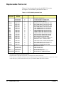
.
.
.
.
.
.
.
.
.
.
.
.
.
.
.
25
25
25
26
27
27
27
Contents
1
Ratio Measurements Test . . . . . .
Trigger Level Test . . . . . . . . .
Operation Verification Tests . . . . . .
Performance Verification Tests . . . .
Frequency Measurements Test . . .
Test Procedure . . . . . . . . . . .
Period Average Measurements Test
Test Procedure . . . . . . . . . . .
Pulse Width Measurements Test . .
Time Interval Measurements Test .
Performance Test Record . . . . . . .
.
.
.
.
.
.
.
.
.
.
.
.
.
.
.
.
.
.
.
.
.
.
.
.
.
.
.
.
.
.
.
.
.
.
.
.
.
.
.
.
.
.
.
.
.
.
.
.
.
.
.
.
.
.
.
.
.
.
.
.
.
.
.
.
.
.
.
.
.
.
.
.
.
.
.
.
.
.
.
.
.
.
.
.
.
.
.
.
.
.
.
.
.
.
.
.
.
.
.
.
.
.
.
.
.
.
.
.
.
.
.
.
.
.
.
.
.
.
.
.
.
.
.
.
.
.
.
.
.
.
.
.
.
.
.
.
.
.
.
.
.
.
.
.
.
.
.
.
.
.
.
.
.
.
.
.
.
.
.
.
.
.
.
.
.
.
.
.
.
.
.
.
.
.
.
.
.
.
.
.
.
.
.
.
.
.
.
.
.
.
.
.
.
.
.
.
.
.
.
.
.
.
.
.
.
.
.
.
.
.
.
.
.
.
.
.
.
.
.
.
.
.
.
.
.
.
.
.
.
.
.
.
.
.
.
.
.
.
.
.
.
.
.
.
.
.
.
.
.
.
.
.
.
.
.
.
.
.
.
.
.
.
.
.
.
.
.
.
.
.
.
.
.
.
.
.
.
.
.
.
.
.
.
.
.
.
29
31
34
35
35
37
40
41
43
46
49
Chapter 5. Adjustments . . . . . . . . . . . . . . . . . . . . . . . . . . . . . . . . . . . . . 55
Introduction . . . . . . . . . . .
Adjustment Requirements . .
Adjustment Access . . . . . .
Reference Oscillator Adjustment
Trigger Level Zero Adjustments
.
.
.
.
.
.
.
.
.
.
.
.
.
.
.
.
.
.
.
.
.
.
.
.
.
.
.
.
.
.
.
.
.
.
.
.
.
.
.
.
.
.
.
.
.
.
.
.
.
.
.
.
.
.
.
.
.
.
.
.
.
.
.
.
.
.
.
.
.
.
.
.
.
.
.
.
.
.
.
.
.
.
.
.
.
.
.
.
.
.
.
.
.
.
.
.
.
.
.
.
.
.
.
.
.
.
.
.
.
.
.
.
.
.
.
.
.
.
.
.
.
.
.
.
.
.
.
.
.
.
.
.
.
.
.
.
.
.
.
.
.
.
.
.
.
55
55
55
56
57
Chapter 6. Replaceable Parts . . . . . . . . . . . . . . . . . . . . . . . . . . . . . . . . . . 61
Introduction . . . . . . .
Exchange Assemblies
Ordering Information .
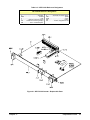
Replaceable Parts List . .
.
.
.
.
.
.
.
.
.
.
.
.
.
.
.
.
.
.
.
.
.
.
.
.
.
.
.
.
.
.
.
.
.
.
.
.
.
.
.
.
.
.
.
.
.
.
.
.
.
.
.
.
.
.
.
.
.
.
.
.
.
.
.
.
.
.
.
.
.
.
.
.
.
.
.
.
.
.
.
.
.
.
.
.
.
.
.
.
.
.
.
.
.
.
.
.
.
.
.
.
.
.
.
.
.
.
.
.
.
.
.
.
.
.
.
.
.
.
.
.
.
.
.
.
.
.
.
.
.
.
.
.
61
61
61
62
Chapter 7. Service . . . . . . . . . . . . . . . . . . . . . . . . . . . . . . . . . . . . . . . . 65
Introduction . . . . . . . . . .
Equipment Required . . . .
Service Aids . . . . . . . .
Troubleshooting Techniques .
Identifying the Problem . .
Testing the Counter . . . . .
Repair/Maintenance Guidelines
ESD Precautions . . . . . .
Post-Repair Safety Checks .
.
.
.
.
.
.
.
.
.
.
.
.
.
.
.
.
.
.
.
.
.
.
.
.
.
.
.
.
.
.
.
.
.
.
.
.
.
.
.
.
.
.
.
.
.
.
.
.
.
.
.
.
.
.
.
.
.
.
.
.
.
.
.
.
.
.
.
.
.
.
.
.
.
.
.
.
.
.
.
.
.
.
.
.
.
.
.
.
.
.
.
.
.
.
.
.
.
.
.
.
.
.
.
.
.
.
.
.
.
.
.
.
.
.
.
.
.
.
.
.
.
.
.
.
.
.
.
.
.
.
.
.
.
.
.
.
.
.
.
.
.
.
.
.
.
.
.
.
.
.
.
.
.
.
.
.
.
.
.
.
.
.
.
.
.
.
.
.
.
.
.
.
.
.
.
.
.
.
.
.
.
.
.
.
.
.
.
.
.
.
.
.
.
.
.
.
.
.
.
.
.
.
.
.
.
.
.
.
.
.
.
.
.
.
.
.
.
.
.
.
.
.
.
.
.
.
.
.
.
.
.
.
.
.
.
.
.
.
.
.
.
.
.
.
.
.
.
.
.
.
.
.
.
.
.
.
.
.
.
.
.
.
.
.
.
.
.
.
.
.
65
65
65
66
66
67
68
68
69
Appendix A. Counter Accuracy Calculations . . . . . . . . . . . . . . . . . . . . . . . . . 71
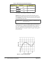
Introduction . . . . . . . . . . . . . . . . . . . . .
Calculating Counter Accuracy . . . . . . . . . . . .
Frequency Measurements Trigger Noise Error .
Period Measurements Trigger Noise Error . . . .
Counter Accuracy Equations Table . . . . . . .
Accuracy Calculations Examples . . . . . . . . . .
Example: Calculating Frequency Accuracy . . .
Effects of Varying Signal Conditions . . . . . .
Example: Calculating Period Average Accuracy
Effects of Varying Signal Conditions . . . . . .
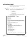
Counter Accuracy Programs . . . . . . . . . . . . .
Frequency Measurement Accuracy . . . . . . .
Period Measurements Accuracy . . . . . . . . .
2
Contents
.
.
.
.
.
.
.
.
.
.
.
.
.
.
.
.
.
.
.
.
.
.
.
.
.
.
.
.
.
.
.
.
.
.
.
.
.
.
.
.
.
.
.
.
.
.
.
.
.
.
.
.
.
.
.
.
.
.
.
.
.
.
.
.
.
.
.
.
.
.
.
.
.
.
.
.
.
.
.
.
.
.
.
.
.
.
.
.
.
.
.
.
.
.
.
.
.
.
.
.
.
.
.
.
.
.
.
.
.
.
.
.
.
.
.
.
.
.
.
.
.
.
.
.
.
.
.
.
.
.
.
.
.
.
.
.
.
.
.
.
.
.
.
.
.
.
.
.
.
.
.
.
.
.
.
.
.
.
.
.
.
.
.
.
.
.
.
.
.
.
.
.
.
.
.
.
.
.
.
.
.
.
.
.
.
.
.
.
.
.
.
.
.
.
.
.
.
.
.
.
.
.
.
.
.
.
.
.
.
.
.
.
.
.
.
.
.
.
.
.
.
.
.
.
.
.
.
.
.
.
.
.
.
.
.
.
.
.
.
.
.
.
.
.
.
.
.
71
71
73
74
74
75
75
76
77
78
79
79
80
HP E1333A Universal Counter Service Manual
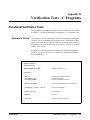
Appendix B. Verification Tests - C Programs . . . . . . . . . . . . . . . . . . . . . . . . . 83
Functional Verification Tests . . . . .
Operator’s Check . . . . . . . . . .
Totalizing Measurement Test . . .
Ratio Measurements Test . . . . . .
Trigger Level Test . . . . . . . . .
Performance Verification Tests . . . .
Frequency Measurements Test . . .
Period Average Measurements . . .
Pulse Width Measurements Test . .
Time Interval Measurements Test .
Counter Accuracy Programs . . . . . .
Frequency Measurement Accuracy
Period Measurements Accuracy . .
HP E1333A Universal Counter Service Manual
.
.
.
.
.
.
.
.
.
.
.
.
.
.
.
.
.
.
.
.
.
.
.
.
.
.
.
.
.
.
.
.
.
.
.
.
.
.
.
.
.
.
.
.
.
.
.
.
.
.
.
.
.
.
.
.
.
.
.
.
.
.
.
.
.
.
.
.
.
.
.
.
.
.
.
.
.
.
.
.
.
.
.
.
.
.
.
.
.
.
.
.
.
.
.
.
.
.
.
.
.
.
.
.
.
.
.
.
.
.
.
.
.
.
.
.
.
.
.
.
.
.
.
.
.
.
.
.
.
.
.
.
.
.
.
.
.
.
.
.
.
.
.
.
.
.
.
.
.
.
.
.
.
.
.
.
.
.
.
.
.
.
.
.
.
.
.
.
.
.
.
.
.
.
.
.
.
.
.
.
.
.
.
.
.
.
.
.
.
.
.
.
.
.
.
.
.
.
.
.
.
.
.
.
.
.
.
.
.
.
.
.
.
.
.
.
.
.
.
.
.
.
.
.
.
.
.
.
.
.
.
.
.
.
.
.
.
.
.
.
.
.
.
.
.
.
.
.
.
.
.
.
.
.
.
.
.
.
.
.
.
.
.
.
.
.
.
.
.
.
.
.
.
.
.
.
.
.
.
.
.
.
.
.
.
.
.
.
.
.
.
.
.
.
.
.
.
.
.
.
.
.
.
.
.
.
.
.
.
.
.
.
.
.
.
.
.
.
.
.
.
.
.
.
.
.
.
.
.
.
.
.
.
.
.
.
.
.
83
83
84
85
87
89
89
90
92
93
95
95
96
Contents
3
Notes
4
Contents
HP E1333A Universal Counter Service Manual
Certification
Hewlett-Packard Company certifies that this product met its published specifications at the time of shipment from the factory. HewlettPackard further certifies that its calibration measurements are traceable to the United States National Institute of Standards and Technology (formerly National Bureau of Standards), to the extent allowed by that organization’s calibration facility, and to the calibration
facilities of other International Standards Organization members.
Warranty
This Hewlett-Packard product is warranted against defects in materials and workmanship for a period of three years from date of shipment. Duration and conditions of warranty for this product may be superseded when the product is integrated into (becomes a part of)
other HP products. During the warranty period, Hewlett-Packard Company will, at its option, either repair or replace products which
prove to be defective.
For warranty service or repair, this product must be returned to a service facility designated by Hewlett-Packard (HP). Buyer shall prepay shipping charges to HP and HP shall pay shipping charges to return the product to Buyer. However, Buyer shall pay all shipping
charges, duties, and taxes for products returned to HP from another country.
HP warrants that its software and firmware designated by HP for use with a product will execute its programming instructions when
properly installed on that product. HP does not warrant that the operation of the product, or software, or firmware will be uninterrupted
or error free.
Limitation Of Warranty
The foregoing warranty shall not apply to defects resulting from improper or inadequate maintenance by Buyer, Buyer-supplied products or interfacing, unauthorized modification or misuse, operation outside of the environmental specifications for the product, or improper site preparation or maintenance.
The design and implementation of any circuit on this product is the sole responsibility of the Buyer. HP does not warrant the Buyer’s
circuitry or malfunctions of HP products that result from the Buyer’s circuitry. In addition, HP does not warrant any damage that occurs as a result of the Buyer’s circuit or any defects that result from Buyer-supplied products.
NO OTHER WARRANTY IS EXPRESSED OR IMPLIED. HP SPECIFICALLY DISCLAIMS THE IMPLIED WARRANTIES OF
MERCHANTABILITY AND FITNESS FOR A PARTICULAR PURPOSE.
Exclusive Remedies
THE REMEDIES PROVIDED HEREIN ARE BUYER’S SOLE AND EXCLUSIVE REMEDIES. HP SHALL NOT BE LIABLE
FOR ANY DIRECT, INDIRECT, SPECIAL, INCIDENTAL, OR CONSEQUENTIAL DAMAGES, WHETHER BASED ON CONTRACT, TORT, OR ANY OTHER LEGAL THEORY.
Notice
The information contained in this document is subject to change without notice. HEWLETT-PACKARD (HP) MAKES NO WARRANTY OF ANY KIND WITH REGARD TO THIS MATERIAL, INCLUDING, BUT NOT LIMITED TO, THE IMPLIED WARRANTIES OF MERCHANTABILITY AND FITNESS FOR A PARTICULAR PURPOSE. HP shall not be liable for errors contained
herein or for incidental or consequential damages in connection with the furnishing, performance or use of this material. This document contains proprietary information which is protected by copyright. All rights are reserved. No part of this document may be photocopied, reproduced, or translated to another language without the prior written consent of Hewlett-Packard Company. HP assumes no
responsibility for the use or reliability of its software on equipment that is not furnished by HP.
U.S. Government Restricted Rights
The Software and Documentation have been developed entirely at private expense. They are delivered and licensed as "commercial computer software" as defined in DFARS 252.227-7013 (Oct 1988), DFARS 252.211-7015 (May 1991) or DFARS 252.227-7014
(Jun 1995), as a "commercial item" as defined in FAR 2.101(a), or as "Restricted computer software" as defined in FAR 52.227-19 (Jun
1987) (or any equivalent agency regulation or contract clause), whichever is applicable. You have only those rights provided for such Software and Documentation by the applicable FAR or DFARS clause or the HP standard software agreement for the product involved.
HP E1333A 3-Channel Universal Counter Service Manual
Edition 4
Copyright © 1996 Hewlett-Packard Company. All Rights Reserved.
HP E1333A 3-Channel Universal Counter Service Manual
5
Documentation History
All Editions and Updates of this manual and their creation date are listed below. The first Edition of the manual is Edition 1. The Edition number increments by 1 whenever the manual is revised. Updates, which are issued between Editions, contain replacement pages
to correct or add additional information to the current Edition of the manual. Whenever a new Edition is created, it will contain all of
the Update information for the previous Edition. Each new Edition or Update also includes a revised copy of this documentation history page.
Edition 1 (Part Number E1333-90010). . . . . . . . . . . . . . . . . . . . . . . . April 1991
Edition 2 (Part Number E1333-90011). . . . . . . . . . . . . . . . . . . . . . . March 1992
Edition 3 (Part Number E1333-90012). . . . . . . . . . . . . . . . . . . . . . . . . June 1996
Edition 4 (Part Number E1333-90013). . . . . . . . . . . . . . . . . . . . December 1996
Safety Symbols
Instruction manual symbol affixed to product. Indicates that the user must refer to the
manual for specific WARNING or CAUTION information to avoid personal injury
or damage to the product.
Alternating current (AC).
Direct current (DC).
Indicates hazardous voltages.
Indicates the field wiring terminal that must
be connected to earth ground before operating the equipment—protects against electrical shock in case of fault.
or
Frame or chassis ground terminal—typically connects to the equipment’s metal
frame.
WARNING
Calls attention to a procedure, practice, or
condition that could cause bodily injury or
death.
CAUTION
Calls attention to a procedure, practice, or condition that could possibly cause damage to
equipment or permanent loss of data.
WARNINGS
The following general safety precautions must be observed during all phases of operation, service, and repair of this product.
Failure to comply with these precautions or with specific warnings elsewhere in this manual violates safety standards of design,
manufacture, and intended use of the product. Hewlett-Packard Company assumes no liability for the customer’s failure to
comply with these requirements.
Ground the equipment: For Safety Class 1 equipment (equipment having a protective earth terminal), an uninterruptible safety earth
ground must be provided from the mains power source to the product input wiring terminals or supplied power cable.
DO NOT operate the product in an explosive atmosphere or in the presence of flammable gases or fumes.
For continued protection against fire, replace the line fuse(s) only with fuse(s) of the same voltage and current rating and type.
DO NOT use repaired fuses or short-circuited fuse holders.
Keep away from live circuits: Operating personnel must not remove equipment covers or shields. Procedures involving the removal
of covers or shields are for use by service-trained personnel only. Under certain conditions, dangerous voltages may exist even with the
equipment switched off. To avoid dangerous electrical shock, DO NOT perform procedures involving cover or shield removal unless
you are qualified to do so.
DO NOT operate damaged equipment: Whenever it is possible that the safety protection features built into this product have been impaired, either through physical damage, excessive moisture, or any other reason, REMOVE POWER and do not use the product until
safe operation can be verified by service-trained personnel. If necessary, return the product to a Hewlett-Packard Sales and Service Office for service and repair to ensure that safety features are maintained.
DO NOT service or adjust alone: Do not attempt internal service or adjustment unless another person, capable of rendering first aid
and resuscitation, is present.
DO NOT substitute parts or modify equipment: Because of the danger of introducing additional hazards, do not install substitute
parts or perform any unauthorized modification to the product. Return the product to a Hewlett-Packard Sales and Service Office for
service and repair to ensure that safety features are maintained.
6
HP E1333A 3-Channel Universal Counter Service Manual
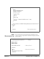
Declaration of Conformity
according to ISO/IEC Guide 22 and EN 45014
Manufacturer’s Name:
Hewlett-Packard Company
Loveland Manufacturing Center
Manufacturer’s Address:815 14th Street S.W.
Loveland, Colorado 80537
declares, that the product:
Product Name:
3-Channel Universal Counter
Model Number(s):
HP E1333A
Product Options:
All
conforms to the following Product Specifications:
Safety:
IEC 348:1978/HD 401 S1:1981
CSA 556B
UL 1244
EMC:
CISPR 11:1990/EN55011 (1991): Group1 Class A
EN50082-1:1992
IEC 801-2:1991: 4kVCD, 8kVAD
IEC 801-3:1984: 3 V/m
IEC 801-4:1988: 1kV Power Line
0.5kV Signal Lines
Supplementary Information: The product herewith complies with the requirements of the Low Voltage Directive
73/23/EEC and the EMC Directive 89/336/EEC and carries the "CE" marking accordingly.
Safety qualification performed February, 1989.
Tested in a typical HP B-size VXI configuration.
September 5, 1996
Jim White, QA Manager
European contact: Your local Hewlett-Packard Sales and Service Office or Hewlett-Packard GmbH, Department
HQ-TRE, Herrenberger Straße 130, D-71034 Böblingen, Germany (FAX +49-7031-143143).
HP E1333A 3-Channel Universal Counter Service Manual
7
Notes
8
HP E1333A 3-Channel Universal Counter Service Manual
Please fold and tape for mailing
Reader Comment Sheet
HP E1333A 3-Channel Universal Counter Service Manual
Edition 4
You can help us improve our manuals by sharing your comments and suggestions. In appreciation of your time, we will
enter you in a quarterly drawing for a Hewlett-Packard Palmtop Personal Computer (U.S. government employees
cannot participate in the drawing).
Your Name
City, State/Province
Company Name
Country
Job Title
Zip/Postal Code
Address
Telephone Number with Area Code
Please list the system controller, operating system, programming language, and plug-in modules you are using.
fold here
cut along this line
NO POSTAGE
NECESSARY
IF MAILED
IN THE
UNITED STATES
BUSINESS REPLY MAIL
FIRST CLASS
PERMIT NO. 37
LOVELAND, CO
HEWLETT-PACKARD COMPANY
Measurement Systems Division
Learning Products Department
P.O. Box 301
Loveland, CO 80539-9984
fold here
Please pencil-in one circle for each statement below:
• The documentation is well organized.
• Instructions are easy to understand.
• The documentation is clearly written.
• Examples are clear and useful.
• Illustrations are clear and helpful.
• The documentation meets my overall expectations.
Please write any comments or suggestions below--be specific.
Disagree
O
O
O
O
O
O
O
O
O
O
O
O
O
O
O
O
O
O
O
O
O
O
O
O
Agree
O
O
O
O
O
O
10
HP E1333A 3-Channel Universal Counter Service Manual
What’s in This Manual
Manual Overview
This manual shows how to service the HP E1333A 3-Channel Universal
Counter. Additional manuals which may be required for servicing the
counter include the HP E1333A User’s Manual which contains counter
operation, installation, and configuration information, and the appropriate
mainframe user’s manual(s) for mainframe operation, installation and
configuration information.
Manual Content
Chapter
Title
Content
1
General Information
Provides a basic description, and lists available options and
accessories. Also lists the tools and test equipment required for
service.
2
Installation
Procedures to install the counter, perform initial inspection, prepare
for use, and store and ship the counter.
3
Operating
Instructions
Procedures to operate the counter, perform scheduled preventive
maintenance, and perform operator’s check.
4
Verification
Tests
Functional verification, operation verification, and performance
verification tests to test the counter.
5
Adjustments
Procedures to adjust the counter to within its rated specifications.
6
Replaceable
Parts
Lists part numbers for user replaceable parts in the counter.
Provides information on ordering spare parts and module/assembly
exchange.
7
Service
Procedures to aid in fault isolation and repair of the counter.
Appx
A
Calculating
Multimeter Accuracy
Shows how counter accuracy is defined and calculated.
Appx
B
Verification Tests C Programs
Gives C Program Examples to do the Verification Tests in Chapter
3 and Chapter 4.
HP E1333A Universal Counter Service Manual
What’s in This Manual
11
Notes
12
What’s in This Manual
HP E1333A Universal Counter Service Manual
Chapter 1
General Information
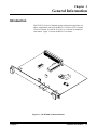
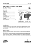
Introduction
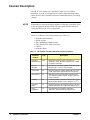
This HP E1333A Service Manual contains information required to test,
adjust, troubleshoot, and repair the HP E1333A B-Size VXI 3-Channel
Universal Counter. See the HP E1333A User’s Manual for additional
information. Figure 1-1 shows the HP E1333A counter.
Figure 1-1. HP E1333A 3-Channel Counter
Chapter 1
General Information
13
Safety Considerations
This product is a Safety Class I instrument that is provided with a protective
earth terminal when installed in the mainframe. The mainframe, counter,
and all related documentation should be reviewed for familiarization with
safety markings and instructions before operation or service.
Refer to the WARNINGS on page 3 in this manual for a summary of safety
information. Safety information for preventive maintenance, testing,
adjusting, and service follows and is also found throughout this manual.
WARNINGS and
CAUTIONS
WARNING
This section contains WARNINGS which must be followed for your
protection and CAUTIONS which must be followed to avoid damage to the
equipment when performing instrument maintenance or repair.
SERVICE-TRAINED PERSONNEL ONLY. The information in
this manual is for service-trained personnel who are familiar
with electronic circuitry and are aware of the hazards involved.
To avoid personal injury or damage to the instrument, do not
perform procedures in this manual or do any servicing unless
you are qualified to do so.
CHECK MAINFRAME POWER SETTINGS. Before applying
power, verify that the mainframe setting matches the line
voltage and the correct fuse is installed. An uninterruptible
safety earth ground must be provided from the main power
source to the mainframe input wiring terminals, power cord, or
supplied power cord set.
GROUNDING REQUIREMENTS. Interruption of the protective
(grounding) conductor (inside or outside the mainframe) or
disconnecting the protective earth terminal will cause a
potential shock hazard that could result in personal injury.
(Grounding one conductor of a two-conductor outlet is not
sufficient protection.)
COMMON GROUND. Verify that a common ground exists
between the unit under test and the counter (via the mainframe)
prior to energizing either unit.
IMPAIRED PROTECTION. Whenever it is likely that instrument
protection has been impaired, the mainframe must be made
inoperative and be secured against any unintended operation.
14
General Information
Chapter 1
REMOVE POWER IF POSSIBLE. Some procedures in this
manual may be performed with power supplied to the
mainframe while protective covers are removed. Energy
available at many points may, if contacted, result in personal
injury. (If maintenance can be performed without power
applied, the power should be removed.)
USING AUTOTRANSFORMERS. If the mainframe is to be
energized via an autotransformer (for voltage reduction) make
sure the common terminal is connected to neutral (that is, the
grounded side of the main’s supply).
WARNING
CAPACITOR VOLTAGES. Capacitors inside the mainframe may
remain charged even when the mainframe has been
disconnected from its source of supply.
USE PROPER FUSES. For continued protection against fire
hazard, replace the line fuse(s) only with fuses of the same
current rating and type (such as normal blow, time delay, etc.).
Do not use repaired fuses or short-circuited fuseholders.
CAUTION
MAXIMUM VOLTAGE. Maximum voltage that may be applied
between any BNC connector is 42 V for the 1 MΩ input
impedance (Channels 1 and 2) and 5 V for the 50 Ω input
impedance (Channels 1, 2, and 3). In general, the limiting factor
is the maximum power which cannot exceed 0.5 W.
STATIC ELECTRICITY. Static electricity is a major cause of
component failure. To prevent damage to the electrical
components in the counter, observe anti-static techniques
when removing a counter from the mainframe or when working
on the counter.
Chapter 1
General Information
15
Counter Description
The HP E1333A counter is an "instrument" in the slots of a VXIbus
mainframe. As such, it is assigned an error queue, input and output buffers,
status registers, and is allocated a portion of mainframe memory for reading
storage.
NOTE
Instruments are based on the logical addresses of the plug-in modules. Refer
to the configuration guide provided with your system for information on
setting the addresses to create an instrument.
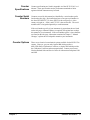
There are six HP E1333A counter functions (see Table 1-1):
•
•
•
•
•
•
Frequency Measurements
Period Average
Pulse Width/Pulse Width Average
Time Interval/Time Interval Average
Totalize
Frequency Ratio
Table 1-1. HP E1333A 3-Channel Universal Counter Functions
Function/
Feature
16
General Information
Chs
Description
Frequency
Measurements
1,2,3
Measure frequency from DC to 100 MHz on
Channels 1 and 2. Measure frequency from 75 MHz
to 1 GHz on Channel 3
Period
Average
1,2
Average from 2 to 65,536 periods of the input signal.
Period range is 1 µsec to 6,871 seconds.
Pulse Width
1,2
Measure positive or negative pulse width of the input
signal. Pulse width range is 200 nsec to 6,871 sec.
Time Interval
1,2
Measure the time interval between transitions from
one channel to another channel. Range is 200 nsec
to 6,871 seconds.
Totalizing
1,2
Count the number of transitions on Channels 1 and 2.
Minimum pulse width is 5 nsec. Range is 1 to 236-1.
Frequency
Ratio
1,2
Measure frequency ratio between Channel 1 and 2 or
between Channel 2 and 1. Min pulse width is 5 nsec.
Input
Capabilities
1,2
Programmable input coupling, termination,
attenuation, low pass filter, and trigger levels.
Chapter 1
Counter
Specifications
Counter specifications are listed in Appendix A of the HP E1333A User’s
Manual. These specifications are the performance standards or limits
against which the instrument may be tested.
Counter Serial
Numbers
Counters covered by this manual are identified by a serial number prefix
listed on the title page. Hewlett-Packard uses a two-part serial number in
the form XXXXAYYYYY, where XXXX is the serial prefix, A is the
country of origin (A = USA), and YYYYY is the serial suffix. The serial
number suffix is assigned sequentially to each instrument.
If the serial number prefix of your instrument is greater than the one listed
on the title page, a Manual Update (as required) will explain how to adapt
this manual to your instrument. If the serial number prefix is lower than the
one listed on the title page, information contained in Chapter 7, "Manual
Changes," explains how to adapt this manual to your instrument.
Counter Options
Chapter 1
There are no electrical or mechanical options available for the HP E1333A
counter. However, you can order Option 1BN which provides a
MIL-STD-45662A Calibration Certificate, or Option 1BP which provides
the Calibration Certificate and measurement data. Contact your nearest
Hewlett-Packard Sales and Service Office for information on Options 1BN
and 1BP.
General Information
17
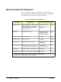
Recommended Test Equipment
Table 1-2 lists the test equipment recommended for testing, adjusting and
servicing the HP E1333A counter. Essential requirements for each piece of
test equipment are described in the Requirements column.
Table 1-2. Recommended Test Equipment
Instrument
Requirements
Recommended Model
Use*
Controller, HP-IB
HP-IB compatibility as defined by IEEE
Standard 488-1978 and the identical
ANSI Standard MC1.1: SH1, AH1, T2,
TEO, L2, LE0, SR0, RL0, PP0, DC0,
DT0, and Cl, 2, 3, 4, 5
HP 9000 Series 300
or
IBM compatible PC with
HP BASIC
A,F,O,
P,T
Mainframe
Compatible with counter
HP E1300A, E1301A,
E1302A, or E1401B/T,
E1421A (requires
E1405A/B or E1406A)
A,F,O,
P,T
Function Generator
0.1 Hz to 10 MHz
HP 3325A
F,O,P
Signal Generator
100 kHz to 1 GHz
HP 8663A
F,O,P
DC Standard
Voltage Range -3.0 V to 30.0 V
Datron 4708
with Option 10
F, O,P
Universal Counter
Frequency Range: 0.1 Hz to 1 GHz
Accuracy: At least equal to HP 5334B
HP 5334B with
(1.3 GHz) C Channel
O,P
Oscilloscope
Frequency Range: 1 kHz to 100 kHz
HP 54111D
A
Digital Multimeter
General Purpose Voltage and Resistance HP 3458A
T
*A = Adjustments, F = Functional Verification, O = Operation Verification Tests,
P = Performance Verification Tests, T = Troubleshooting
18
General Information
Chapter 1
Chapter 2
Installation
Introduction
This chapter provides information to install the HP E1333A counter,
including initial inspection, preparation for use, environment, storage and
shipment.
Initial Inspection
Inspect the shipping container for damage. If the shipping container or
cushioning material is damaged, keep the container until the shipment
contents have been checked and the instrument has been checked
mechanically and electrically. See Chapter 1 (Figure 1-1) for shipment
contents. See Chapter 4 for procedures to check electrical performance.
WARNING
To avoid possible hazardous electrical shock, do not perform
electrical tests if there are signs of shipping damage to any
portion of the outer enclosure (covers, panels, etc.).
If the contents are incomplete, if there is mechanical damage or defect, or if
the instrument does not pass the electrical performance tests, notify your
nearest Hewlett-Packard Sales and Service Office. If the shipping container
is damaged or the cushioning material shows signs of stress, notify the
carrier as well as Hewlett-Packard, and keep the shipping materials for the
carrier’s inspection.
Preparation for Use
See Chapter 2 of the HP E1333A User’s Manual to prepare the HP E1333A
counter for use. See the appropriate mainframe user’s manual(s) to prepare
your mainframe. If your mainframe is not manufactured by
Hewlett-Packard, consult the manufacturer for a list of available manual(s).
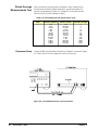
Recommended operating environment for the HP E1333A counter is 0oC to
+55oC with humidity <65% relative (0oC to +40oC). The instrument should
be stored in a clean, dry environment. For storage and shipment, the
temperature range is -40oC to +75oC with humidity <65% relative (0oC to
+40oC).
Chapter 2
Installation
19
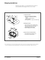
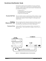
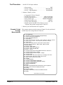
Shipping Guidelines
Follow the steps in Figure 2-1 to return the HP E1333A counter to a
Hewlett-Packard Sales and Support Office or Service Center.
1. Prepare the Counter
+ Remove user wiring from the module
+ Attach tag to ,module/pod that identifies
- Owner
- Model Number/Serial Number
- Service required
+ Place tagged device in approved anti-static bag
2. Package the Counter
+ Place packaged counter in shipping carton *
+ Place 75 to 100 mm (3 to 4 inches) of shockabsorbing marerial around the counter
+ Seal the shipping carton securely
+ Mark the shipping carton FRAGILE
3. Ship the Counter to Hewlett-Packard
+ Place address label on shipping carton
+ Send carton to Hewlett-Packard
Figure 2-1. Packaging/Shipping Guidelines
* We recommend that you use the same shipping materials as those used in factory packaging (available from Hewlett-Packard).
For other (commercially-available) shipping materials, use a double wall-carton with minimum 2.4 MPa (350 psi) test.
20
Installation
Chapter 2
Chapter 3
Operating Instructions
Introduction
This chapter lists operating information for the HP E1333A counter,
including:
• Counter operation
• Preventive maintenance
• Operator’s check (self-test)
Counter Operation
See the HP E1333A 3-Channel Universal Counter User’s Manual for
counter operation, including:
•
•
•
•
Getting started
Configuring the counter
Using the counter
Understanding the counter
• Counter command reference
• Counter specifications
• Counter error messages
Preventive Maintenance
Preventive Maintenance for the HP E1333A counter consists of periodically
cleaning the counter and then running the Operator’s Check (*TST?
command). For best results, you should clean the counter once a year or
more often if the counter is used in a very dusty or very humid area. See
Table 3-1 for recommended cleaning equipment and supplies.
Chapter 3
Description
Recommended Use
Soft-bristle brush
Mild soap solution
Lint-free cloth
Remove dust from printed circuit board
Clean faceplate panel
Clean faceplate panel
Operating Instructions
21
WARNINGS and
CAUTIONS
WARNING
CAUTION
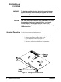
Cleaning Procedure
To eliminate possible electrical shock, disconnect AC power
from the mainframe and disconnect all inputs to the counter
before removing the counter from the mainframe.
Use static control devices (wrist straps, static mats, etc.) when
handling the printed circuit assembly. Also, do not use a
vacuum cleaner to remove dust from the printer circuit
assembly. See Chapter 8, "Service," for electrostatic discharge
(ESD) precautions.
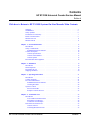
Use the following steps to clean the counter:
1.
2.
3.
4.
5.
Disconnect any user wiring connected to the input terminals.
Remove dust from the printed circuit surface.
Clean all contacts indicated in Figure 3-1.
Clean the faceplate panel using a lint-free cloth.
Reconnect user wiring to the counter input connectors.
Figure 3-1. Cleaning the HP E1333A Counter
22
Operating Instructions
Chapter 3
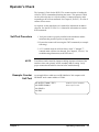
Operator’s Check
The Operator’s Check for the HP E1333A counter consists of sending the
self-test (*TST?) command and checking the return. The operator’s check
can be used at any time to verify the counter is connected properly and is
responding to the self-test command. See Chapter 8, "Service," for a list of
counter self-test errors.
As required, see the mainframe user’s manual for information on address
selection. See the HP E1333A User’s Manual for information on counter
SCPI commands.
Self-Test Procedure
1. Verify the counter is properly installed in the mainframe and the
mainframe has passed its power-on sequence test.
2. Execute the counter self-test using the *TST? command (see example
following).
3. A "0" returned means no self-test failure, while "1" through "7"
returned means a failure was detected. See Chapter 8, "Service," for
troubleshooting information (see NOTE below).
NOTE
Example: Counter
Self-Test
Test failures can be caused by improper cabling, improper selection of the
interface select code, primary, and/or secondary address setting. Verify
proper connection and address selection before troubleshooting.
An example follows which uses an HP 9000 Series 300 computer with
HP BASIC and a counter address of 70906.
10 OUTPUT 70906;"*TST?"
!Send the self-test command
20 ENTER 70906;A
!Enter self-test result
30 PRINT A
40 END
Chapter 3
Operating Instructions
23
Notes
24
Operating Instructions
Chapter 3
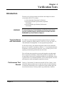
Chapter 4
Verification Tests
Introduction
The three levels of test procedures described in this chapter are used to
verify that the HP E1333A counter:
• is fully functional (Functional Verification)
• meets selected testable specifications (Operation
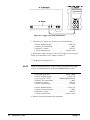
Verification)
• meets all testable specifications (Performance
Verification)
WARNING
Test Conditions
and Procedures
Do not perform any of the following verification tests unless
you are a qualified service trained person and have read the
WARNINGS and CAUTIONS In Chapter 1.
For valid tests, all test equipment and the counter must have a one hour
warm-up, and the line voltage must be 115/230 Vac ± 10%. See Table 1-2,
"Recommended Test Equipment," for test equipment requirements.
For best test accuracy, the ambient temperature of the test area should be
between 18°C and 28°C and stable to within ± 1°C. You should perform the
Performance Verification tests at least once a year. For heavy use or severe
operating environments, perform the tests more often.
The verification tests assume the person performing the tests understands
how to operate the mainframe, counter and specified test equipment. The
test procedures do not specify equipment settings for test equipment, except
in general terms. It is assumed a qualified, service-trained person will select
and connect the cables and adapters required for the tests.
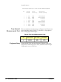
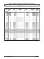
Performance Test
Record
Chapter 4
Table 4-8, "Performance Test Record for the HP E1333A Counter," at the
end of this chapter provides space to enter the results of each Performance
Verification test and allows you to compare the results with the upper and
lower limits for the test. You may make a copy of this form, if desired.
Verification Tests
25
NOTE
The Performance Verification tests assume the test equipment used is
calibrated and is operating at peak performance. If this is not the case,
problems can occur.
For example, an uncalibrated source may cause what seems to be an
inaccurate measurement. This condition must be considered when observed
measurements do not agree with the performance test limits.
The value in the "Measurement Uncertainty" column of Table 4-8 is derived
from the specifications for the source used for the test, and represents the
expected accuracy of the source. The values in Table 4-8 assume the source
is externally locked to a "house standard" with accuracy = ± (3 x 10-11) x
measurement, so the measurement uncertainty is that of the house standard.
The value in the Test Accuracy Ratio (TAR) column of Table 4-8 is the
ratio of counter accuracy to measurement uncertainty, rounded to the
nearest integer for TARs <10:1, or shown as ">10:1" for TARs >10:1. For
example, if counter accuracy = ±6.0 x 10⁻⁶ Hz and measurement uncertainty
= ± 3.0 x 10⁻⁷ Hz, TAR = ± (6.0 x 10⁻⁶/3.0 x 10-7) = ± 20:1. Since this is
>10:1, the entry in Table 4-8 is ">10:1".
Verification Test
Examples
Each performance verification test includes an example program to perform
the test. Each example uses address 70906 for the counter, and an HP 9000
Series 200/300 computer running HP BASIC and SCPI (Standard
Commands for Programmable Instruments) commands. You may need to
change the counter address and/or command syntax to perform the
examples for your setup.
As required, see the mainframe user’s manual for information on address
selection and cabling guidelines. See the HP E1333A User’s Manual for
information on counter SCPI commands.
26
Verification Tests
Chapter 4
Functional Verification Tests
The functional verification tests for the HP E1333A can be performed at
any time to verify the counter is functional and is communicating with the
mainframe, external computer and/or external terminal. The functional tests
for the HP E1333A counter are:
•
•
•
•
Counter Self-Test
Totalizing Measurements Test (Optional)
Ratio Measurements Test (Optional)
Trigger Level Test (Optional)
Counter Self-Test
This test verifies the counter is communicating with the mainframe, external
controller, and/or external terminal by performing a counter self-test (*TST?
command). See "Operator’s Checks" in Chapter 3 for a description of the
counter self-test.
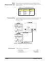
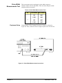
Totalizing
Measurement Test
This test verifies the totalize measurement functions on Channels 1 and 2 at
1 Hz and 4 MHz. The test passes if the count increments on each channel.
The test fails if the count remains at 0 for either or both channels.
Equipment Setup
Connect an HP 3325A function generator to Channel 1 and Channel 2 as
shown in Figure 4-1. Then, set the HP 3325A output to 1 Hz sine wave at
50 mV rms.
Figure 4-1. Totalizing Measurements Test Connections
Chapter 4
Verification Tests
27
Test Procedure
1. Set HP E1333A input conditions
• Reset counter . . . . . . . . . . . . . . . . . . . . . . . . . . . . . . . . . *RST
• Set DC coupling . . . . . . . . . . . . . . . . . . . . . . . INP:COUP DC
• Set 50Ω input impedance . . . . . . . . . . . . . . . . INP:IMP MIN
2. Totalize counts for 1 Hz input
•
•
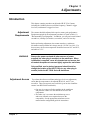
•
•
•
•
•
Channel 1 to TOTalize . . . . . . . . . . . . . . . . . . . CONF1:TOT
Channel 2 to TOTalize. . . . . . . . . . . . . . . . . . . . CONF2:TOT
Initiate measurement on Ch 1 . . . . . . . . . . . . . . . . . . . . INIT1
Return Ch 1 results. . . . . . . . . . . . . . . . . . . . . . . . . . FETC1?
Initiate measurement on Ch 2 . . . . . . . . . . . . . . . . . . . . INIT2
Return Ch 2 results. . . . . . . . . . . . . . . . . . . . . . . . . . FETC2?
Verify count increments on both channels
3. Totalize count for 4 MHz input
• After 10-15 counts, set source to . . . . . . . . . . 4 MHz output
• Repeat Step 2 for 4 MHz output
4. Remove power and disconnect test equipment
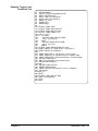
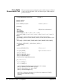
Example: Totalizing
Measurements
Functional Test
10 PRINT "Totalize counts for the following inputs:"
20 PRINT
30 PRINT "1 Hz, 50 mV rms sinewave"
40 PRINT "4 MHz, 50 mV rms sinewave"
50 DISP " Press any key to stop the program"
60 ON KBD GOTO Quit
70 OUTPUT 70906;"*RST"
80 OUTPUT 70906;"INP:COUP DC"
90 OUTPUT 70906;"INP:IMP MIN"
100 FOR Chan= 1 TO 2
110 OUTPUT 70906;"CONF"&VAL$(Chan)&":TOT"
120 OUTPUT 70906;"INIT"&VAL$(Chan)
130 NEXT Chan
140 Start: !
150 FOR Chan = 1 TO 2
160 OUTPUT 70906;"FETC"&VAL$(Chan)&"?"
170 ENTER 70906;Reading(Chan)
180 PRINT TABXY(1,7+Chan);"Channel ";Chan;" total counts =
";Reading(Chan)
190 NEXT Chan
200 GOTO Start
210 Quit: !
220 CLEAR SCREEN
230 END
28
Verification Tests
Chapter 4
Ratio
Measurements Test
This test checks the ratio measurements function of the HP E1333A for
Channel 1/Channel 2, using Channel 1 and Channel 2 frequencies and ratios
shown in Table 4-1.
Table 4-1. Ch 1/Ch 2 Ratio Measurements
Equipment Setup
Ch 1 Freq
Ch 2 Freq
Ch 1/Ch 2
Ratio
1 MHz
1 MHz
1 MHz
1 MHz
1 MHz
100 Hz
1 kHz
10 kHz
100 kHz
1 MHz
10000
1000
100
10
1
Connect the equipment as shown in Figure 4-2. Then, set the Channel 1 and
Channel 2 sources to output sine waves at 50 mV rms. Set Channel 1
frequency to 1 MHz
Figure 4-2. Ratio Measurements Test Connections
Test Procedure
1. Set the HP E1333A input conditions
• Reset Counter . . . . . . . . . . . . . . . . . . . . . . . . . . . . . . . . . *RST
• Coupling to DC . . . . . . . . . . . . . . . . . . . . . . . INP:COUP DC
• Input impedance to 50Ω. . . . . . . . . . . . . . . . . . INP:IMP MIN
Chapter 4
Verification Tests
29
2. Measure Ch 1/Ch 2 ratio at 100 Hz on Ch 2
•
•
•
•
•
•
Set Ch 1 source output . . . . . . . . . . . . . . . . . . . . . . . . 1 MHz
Set Ch 2 source output . . . . . . . . . . . . . . . . . . . . . . . . 100 Hz
Set Ch 1 function, range, resolution . CONF1:RAT 1E6,1E3
Initiate Ch 1/Ch 2 ratio meas . . . . . . . . . . . . . . . . . . . . . INIT1
Return Ch 1/Ch 2 ratio results . . . . . . . . . . . . . . . . . FETC1?
Verify returned result . . . . . . . . . . . . . . . . . . . . . . . . . . 10000
3. Repeat Step 2 for each Ch 2 frequency in Table 4-1.
4. Remove power and disconnect test equipment
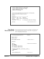
Example: Ratio
Measurements
Functional Test
10 PRINT "Ch 1/Ch 2 ratio measurement"
20 PRINT
30 PRINT "Procedure:"
40 PRINT
50 PRINT " 1. Set Ch 1 source to 50 mV rms sine wave at 1 MHz "
60 PRINT " 2. Set Ch 2 source to 50 mV rms sine wave."
70 PRINT " 3. Vary Ch 2 freq from 100 Hz to 1 MHz (5 steps)."
80 PRINT " 4. Check Ch 1/Ch 2 ratio at each frequency step."
90 DISP " Press any key to stop the program "
100 ON KBD GOTO Quit
110 OUTPUT 70906;"*RST"
120 OUTPUT 70906;"INP:COUP DC"
130 OUTPUT 70906;"INP:IMP MIN"
140 Start: !
150 OUTPUT 70906;"CONF1:RAT 1E6,1E3"
160 OUTPUT 70906;"INIT1"
170 WAIT 1
180 OUTPUT 70906;"FETC1?"
190 ENTER 70906;Rdg
200 OUTPUT 70906;"MEAS2:FREQ?"
210 ENTER 70906;Ch2_freq
220 Ch2_freq = PROUND(Ch2_freq,2)
230 PRINT TABXY(1,12);"Results:"
240 PRINT TABXY(5,14);"Ch 2 frequency = ";Ch2_freq;"Hz
"
250 PRINT TABXY(5,15);"Ch 1/Ch 2 ratio = ";Rdg;"
"
260 GOTO Start
270 Quit: !
280 CLEAR SCREEN
290 END
30
Verification Tests
Chapter 4
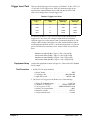
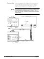
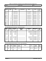
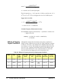
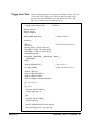
Trigger Level Test
This test checks the trigger level accuracy on Channel 1 for the -2.56V, 0V,
+2.54V and +25.4V trigger levels. Table 4-2 shows the trigger levels
measured, the input attenuation level in dB, and the below-level and
above-level voltage values for each trigger level.
Table 4-2. Trigger Level Tests
Trigger Level
(V)
Input Attenuation
(dB)
Below-Level
Value (V)
Above-Level
Value (V)
-2.56
0
-2.836
-2.284
+0.00
0
-0.02
+0.02
+2.54
0
+2.266
+2.814
+25.4
20
+22.66
+28.14
For this test, the HP E1333A is set to TOTalize mode and the desired
trigger level is set. Next, a DC voltage is input which is less than the
specified trigger level value and the count is measured (should be 0). The
voltage is then set above the trigger level value and the totalized count is
measured again (should be at least 1). If the increased count is >0, the test
passes. The below-level and above-level values in Table 4-2 are derived
from:
Below-Level Value (0 dB) = Trig Lvl - |.02 + |Trig Lvl/10||
Above-Level Value (0 dB) = Trig Lvl + |.02 + |Trig Lvl/10||
Below-Level Value (20 dB) = Trig Lvl - |.20 + |Trig Lvl/10||
Above-Level Value (20 dB) = Trig Lvl + |.20 + |Trig Lvl/10||
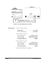
Equipment Setup
Test Procedure
Connect the equipment as shown in Figure 4-3. Then, set the DC Standard
for DC output.
1. Set HP E1333A input conditions
• Reset Counter . . . . . . . . . . . . . . . . . . . . . . . . . . . . . . . . . *RST
• Coupling to DC . . . . . . . . . . . . . . . . . . . . . . . INP:COUP DC
• Input filter to ON . . . . . . . . . . . . . . . . . . . . . . . . INP:FILT ON
2. Test Low-Level Trigger Levels (Below-Level Value Setting)
•
•
•
•
•
•
Chapter 4
Set the DC Standard output . . . . . . . . . . . . . . . . . -2.836 Vdc
Channel 1 to TOTalize. . . . . . . . . . . . . . SENS1:FUNC:TOT
Ch 1 trig lvl to -2.56V . . . . . . . . . . SENS1:EVEN:LEV -2.56
Initiate Ch 1 measurement . . . . . . . . . . . . . . . . . . . . . . . INIT1
Return Ch l results . . . . . . . . . . . . . . . . . . . . . . . . . . FETC1?
Verify returned result . . . . . . . . . . . . . . . . . . . . . . . . 0 counts
Verification Tests
31
Figure 4-3. Trigger Level Tests Connections
3. Test Low-Level Trigger Levels (Above-Level Value Setting)
•
•
•
•
Set DC Standard output . . . . . . . . . . . . . . . . . . . . -2.284 Vdc
Initiate Ch 1 measurment . . . . . . . . . . . . . . . . . . . . . . . . INIT1
Return Ch 1 results. . . . . . . . . . . . . . . . . . . . . . . . . . FETC1?
Verify returned result . . . . . . . . . . . . . . . . . . . at least 1 count
4. Repeat Steps 2 and 3 for the 0 V and +2.54 V trigger levels, using the
Below-Level and Above-Level Values in Table 4-2.
5. Test High-Level Trigger Level
NOTE
When the input attenuation is 20 dB, you must divide the desired trigger
level by 10, and then enter the result using SENS:EVEN:LEV value.
•
•
•
•
•
•
Set 20 dB input atten . . . . . . . . . . . . . . . . . . . . INP:ATT MAX
Set DC Standard output . . . . . . . . . . . . . . . . . . . . +22.66 Vdc
Ch 1 trig lvl to +25.4V . . . . . . . . . . SENS1:EVEN:LEV 2.54
Initiate Ch 1 measurement . . . . . . . . . . . . . . . . . . . . . . . INIT1
Return Ch 1 results. . . . . . . . . . . . . . . . . . . . . . . . . . FETC1?
Verify returned result . . . . . . . . . . . . . . . . . . . . . . . . 0 counts
•
•
•
•
Set DC Standard output . . . . . . . . . . . . . . . . . . . . +28.14 Vdc
Initiate Ch 1 measurement . . . . . . . . . . . . . . . . . . . . . . . INIT1
Return Ch 1 results. . . . . . . . . . . . . . . . . . . . . . . . . . FETC1?
Verify returned result . . . . . . . . . . . . . . . . . . . at least 1 count
6. Remove power and disconnect test equipment
32
Verification Tests
Chapter 4
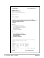
Example: Trigger Level
Functional Test
10 OPTION BASE 1
20 DIM Trig_ lev(4),Low(4),High(4),Lvl(4)
30 DATA -2.56,0,2.54,25.4
40 DATA -2.836,-.02,2.266,22.66
50 DATA -2.284,.02,2.814,28.14
60 READ Trig_ lev(*)
70 READ Low(*)
80 READ High(*)
90 !
100 OUTPUT 70906;"*RST"
110 OUTPUT 70906;"INP:COUP DC"
120 OUTPUT 70906;"INP:FILT ON"
130 OUTPUT 70906;"CONF1:TOT"
140 FOR I = 1 TO 4
150 IF I = 4 THEN
160
OUTPUT 70906;"1NP:ATT MAX"
170
Lvl(I) = Trig_lev(I)/10
180
ELSE
190
OUTPUT 70906;"INP:ATT MIN"
200
Lvl(I) = Trig_Lvl(I)
210
END IF
220 OUTPUT 70906;"SENS1:EVEN:LEV";Lvl(I)
230 PRINT TABXY(1,1);"Trigger level= ";Trig_lev(I);"V"
240 PRINT TABXY(1,4);"Procedure:"
250 !
260 PRINT TABXY(5,6);"1. Set source to ";Low(I);"Volts. "
270 PRINT TABXY(5,7);"2. Increase source to ";High(I);"Volts. "
280 PRINT TABXY(5,8);"3. Verify that Channel 1 count increases."
290 OUTPUT 70906;"INIT1"
300 DISP "For next trigger level, press any key."
310 ON KBD GOTO Next_lvl
320 Start: !
330 OUTPUT 70906;"FETC1?"
340 ENTER 70906;Reading
350 PRlNT TABXY(10,12);"Channel 1 count = ";Reading;"
"
360 GOTO Start
370 Next_lvl: !
380 NEXT I
390 OUTPUT 70906;"INP:ATT MIN"
400 DISP "Test completed."
410 STOP
420 END
Chapter 4
Verification Tests
33
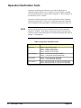
Operation Verification Tests
Operation verification test objectives are to instill a high degree of
confidence that the HP E1333A 3-Channel Universal Counter is meeting
selected specifications from those listed in Appendix A, "Specifications," in
the HP E1333A User’s manual.
Operation verification tests can be used in applications such as incoming
inspection and after HP E1333A repair. To perform operation verification
tests, do the parts of the performance verification tests shown in Table 4-3.
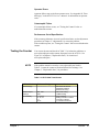
NOTE
For best results, the HP E1333A 10 MHz reference oscillator should be
adjusted to 10 MHz ± 10Hz. Before using the operation verification tests,
you may want to perform the Reference Oscillator Adjustment procedure in
Chapter 5, "Adjustments."
Table 4-3. Operation Verification Tests
Test
34
Verification Tests
Test These Specifications
Frequency
Chan 1: 1 kHz, 8.192 sec gate
Chan 1: 1 MHz, 1.024 sec gate
Chan 2: 100 MHz, 0.002 sec gate
Chan 3: 400 MHz, 0.016 sec gate
Period average
Chan 1: 1 msec period, average 16 periods
Chan 1: 1 µsec period, average 1024 periods
Pulse Width
Chan 1: 1 msec pulse width, POS pulse
Chan 2: 1 msec pulse width, POS pulse
Time Interval
Chan 1: 500 nsec interval, Ch 1 POS to Ch 2 NEG edge
Chan 2: 500 nsec Interval, Ch 2 POS to Ch 1 NEG edge
Chapter 4
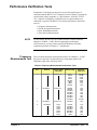
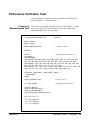
Performance Verification Tests
Performance verification test objectives are to instill a high degree of
confidence that the HP E1333A 3-Channel Universal Counter is meeting the
specifications listed in Appendix A, "Specifications," of the HP E1333A
User’s Manual. Performance verification tests are required whenever a
calibration is required. The HP E1333A counter performance verification
tests are:
•
•
•
•
NOTE
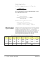
Frequency
Measurements Test
Frequency Measurements
Period Average Measurements
Pulse Width Measurements
Time Interval Measurements
For best results, the HP E1333A 10 MHz reference oscillator should be
adjusted to 10 MHz ± 10 Hz. Before beginning the performance
verification tests, you may want to perform the Reference Oscillator
Adjustment procedure in Chapter 5 - "Adjustments."
This test checks frequency measurement accuracy on Channels 1, 2, and 3.
Input level sensitivity is tested indirectly by using input signals with
amplitudes equal to the sensitivity limits.
Table 4-4. Frequency Measurements Performance Tests
Ch
Source Ampl
(mV rms)
Source Freq
Aperture
Time (sec)
1
HP 3325A
25 mV rms
10 Hz
100 Hz
1 kHz
10 kHz
100 kHz
1 MHz
4 MHz
10 MHz
32.768
16.384
8.192
4.096
2.048
1.024
.512
.256
1
HP 8663A
25 mV rms
20 MHz
50 MHz
100 MHz
100 MHz
100 MHz
100 MHz
100 MHz
100 MHz
.128
.064
.032
.016
.008
.004
.002
65.536
2
HP 8663A
25 mV rms
100 MHz
.002
75 MHz
100 MHz
200 MHz
400 MHz
600 MHz
900 MHz
1 GHz
.128
.064
.032
.016
.008
.004
.002
3
Chapter 4
Source
HP 8663A
10 mV
10 mV
10 mV
10 mV
10 mV
30 mV
40 mV
Verification Tests
35
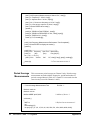
Equipment Setup
NOTE
Connect the equipment as shown in Figure 4-4. For measurements from
10 Hz through 10 MHz, connect the HP 3325A Function Generator to
Channel 1. For measurements above 10 MHz, connect the HP 8663A
Signal Generator to Channel 1, 2 or 3. Set outputs for sine wave.
If a frequency test fails, measure the ACTUAL input to the HP E1333A to
ensure that the input is the appropriate value (25 mV, 10 mV, 30 mV, or
40 mV rms). If the input is less than the specified value, increase the source
output as required.
Figure 4-4. Frequency Measurements Test Connections
36
Verification Tests
Chapter 4
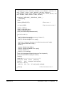
Test Procedure
1. Set HP E1333A input conditions:
• Reset counter . . . . . . . . . . . . . . . . . . . . . . . . . . . . . . . . . *RST
• Set DC coupling . . . . . . . . . . . . . . . . . . . . . . . INP:COUP DC
• Set 50Ω input impedance . . . . . . . . . . . . . . . . INP:IMP MIN
2. Measure Channel 1 frequencies (HP 3325A Source)
•
•
•
•
•
•
•
Connect HP 3325A to Channel 1
Set HP 3325A output . . . . . . . . . . . . . . . 10 Hz at 25 mV rms
Set FREQ function on Ch 1 . . . . . . . . . SENS1:FUNC:FREQ
Set 32.768 sec aperture . . . . . . SENS1:FREQ:APER 32.768
Read measurement result . . . . . . . . . . . . . . . . . . . . . READ1?
Verify result within limits . . . . . . . . . . . . . . . . . . . Table 4-8
Repeat steps for each HP 3325A Channe1 source
frequency, source amplitude and aperture time entry in
Table 4-4.
3. Measure Channel 1 frequencies (HP 8663A Source)
•
•
•
•
•
•
Connect HP 8663A to Channel 1
Set HP 8663A output . . . . . . . . . . . . 20 MHz at 25 mV rms
Set .128 sec aperture . . . . . . . . SENS1 :FREQ:APER .128
Read measurement result . . . . . . . . . . . . . . . . . . . . READ1?
Verify result within limits . . . . . . . . . . . . . . . . . . Table 4-8
Repeat steps for each HP 8663A Channel 1 source
frequency, source amplitude and aperture time entry in
Table 4-4
4. Measure Channel 2 frequency (HP 8663A Source)
•
•
•
•
•
Connect HP 8663A to Channel 2
Set HP 8663A output . . . . . . . . . . . . 100 MHz at 25 mV rms
Set .002 sec aperture . . . . . . . . . . SENS2:FREQ:APER .002
Read measurement result . . . . . . . . . . . . . . . . . . . . . READ2?
Verify result within limits . . . . . . . . . . . . . . . . . . . Table 4-8
5. Measure Channel 3 frequencies (HP 8663A Source)
•
•
•
•
•
•
Connect HP 8663A to Channel 3
Set HP 8663A output . . . . . . . . . . . . . 75 MHz at 10 mV rms
Set .128 sec aperture . . . . . . . . . . SENS3:FREQ:APER .128
Read measurement result . . . . . . . . . . . . . . . . . . . . . READ3?
Verify result within limits . . . . . . . . . . . . . . . . . . . Table 4-8
Repeat steps for each HP 8663A Channel 3 source
frequency, source amplitude and aperture time entry in
Table 4-4
6. Remove power and disconnect test equipment
Chapter 4
Verification Tests
37
Example: Frequency
Measurements Test
NOTE
This program measures frequency on Channels 1, 2, and 3 for the
frequencies and aperture times shown in Table 4-4.
Some measurements take up to 65 seconds to complete. If a measurement
appears to take too long, check connections and/or code you entered.
10 OPTION BASE 1
20 DIM Aper(24),Ampl$(24)[10],Freq(24),Freq$(24)[10], Chan(24),Read(24)
30 DATA 32.768, 16.384, 8.192, 4.096, 2.048, 1.024, .512, .256
40 DATA .128, .064, .032, .016, .008, .004, .002, 65.536
50 DATA.002,.128,.064,.032,.016,.008,.004,.002
60 READ Aper(*)
70 DATA 25 mV, 25 mV, 25 mV, 25 mV, 25 mV, 25 mV, 25 mV, 25 mV
80 DATA 25 mV, 25 mV, 25 mV, 25 mV, 25 mV, 25 mV, 25 mV, 25 mV
90 DATA 25 mV, 10 mV, 10 mV, 10 mV, 10 mV, 10 mV, 30 mV, 40 mV
100 READ Ampl$(*)
110 DATA 1.E1,1.E2,1.E3,1.E4,1.E5,1.E6,4.E6,1.E7
120 DATA 2.E7,5.E7,1.E8,1.E8,1.E8,1.E8,1.E8,1.E8
130 DATA 1.E8,7.5E7,1.E8,2.E8,4.E8,6.E8,9.E8,1.E9
140 READ Freq(*)
150 DATA 10 Hz, 100 Hz, 1 kHz, 10 kHz, 100 kHz, 1 MHz, 4 MHz, 10 MHz
160 DATA 20 MHz, 50 MHz, 100 MHz, 100 MHz, 100 MHz, 100 MHz, 100
MHz, 100 MHz
170 DATA 100 MHz, 75 MHz, 100 MHz, 200 MHz, 400 MHz, 600 MHz, 900
MHz, 1 GHz
180 READ Freq$(*)
190 OUTPUT 70906;"*RST"
200 OUTPUT 70906;"INP:COUP DC"
210 OUTPUT 70906;"INP:IMP MIN"
220 FOR I = 1 TO 24
230 IF I < 17 THEN Chan(I) = 1
240 IF I = 17 THEN Chan(I) = 2
250 IF I > 17 THEN Chan(I) = 3
260 OUTPUT CRT;"Frequency Measurernents on Channel";Chan(I)
270 OUTPUT CRT;"Frequency = ";Freq$(I)
280 OUTPUT CRT;"Aperture time = ";Aper(I);" sec"
290 OUTPUT CRT;" "
300 OUTPUT CRT;" Set source frequency to ";Freq$(I)
310 OUTPUT CRT;" Set source output to ";Ampl$(I);" rms"
320 DISP " Press Continue when ready "
330 PAUSE
340 CLEAR SCREEN
350 OUTPUT 70906;"SENS"&VAL$(Chan(I))&":FUNC:FREQ"
360 OUTPUT 70906;"SENS"&VAL$(Chan(I))&":FREQ:APER ";Aper(I)
370 OUTPUT 70906;"READ"&VAL$(Chan(I))&"?"
380 ENTER 70906;Read(I)
390 NEXT I
400 PRINT "Frequency Measurments Performance Test Completed."
410 PRINT "Press Continue to display the results."
420 PAUSE
430 CLEAR SCREEN
440 PRINT " HP E1333A counter Frequency Measurements"
450 PRINT
460 Format:IMAGE 4X,2A,4X,9A,5X,9A,8X,9A
470 PRINT USING Format;"Ch";"Frequency";"Aper Time";"Measured"
480 PRINT USING Format;" ";"(Hz)";"(sec)";"Freq (Hz)"
490 PRINT
500 Format1:1MAGE 4X,D,5X,7A,6X,2D.3D,7X,10D.3D
510 FOR I = 1 TO 24
520 PRINT USING Format1;Chan(I);Freq$(I);Aper(I);Read(I)
530 NEXT I
540 END
38
Verification Tests
Chapter 4
A typical return is:
HP E1333A Counter Frequency Measurements
Ch
1
1
1
3
Chapter 4
Frequency
(Hz)
10 Hz
100 Hz
1 kHz
.
.
.
1 GHz
Aper Time
(sec)
32.768
16.384
8.192
0.002
Measured
Freq (HZ)
9.979
99.976
999.878
1000003001.000
Verification Tests
39
Period Average
Measurements Test
This test measures period averages on Channel 1 only. Period average
measurements are made with the frequencies, periods and number of
periods averaged shown in Table 4-5. (Channel 2 is not tested since the
same circuitry is used for Channels 1 and 2.)
Table 4-5. Period Measurements Performance Tests
Equipment Setup
Chan
Source Frequency
Source Period
Periods Averaged
1
1 Hz
10 Hz
100 Hz
1 kHz
5 kHz
10 kHz
50 kHz
100 kHz
500 kHz
1 MHz
2 MHz
5 MHz
10 MHz
1 sec
100 msec
10 msec
1 msec
200 usec
100 usec
20 usec
10 usec
2 usec
1 usec
500 nsec
200 nsec
100 nsec
2
4
8
16
32
64
128
256
512
1024
2048
4096
8192
Connect an HP 3325A Function Generator to Channel 1 as shown in Figure
4-5. Then, set HP 3325A to output sine waves at 50 mV rms.
Figure 4-5. Period Measurements Test Connections
40
Verification Tests
Chapter 4
Test Procedure
1. Set HP E1333A Input conditions
• Reset counter . . . . . . . . . . . . . . . . . . . . . . . . . . . . . . . . . *RST
• Set DC coupling . . . . . . . . . . . . . . . . . . . . . . . INP:COUP DC
• Set 50Ω Input Impedance . . . . . . . . . . . . . . . . INP:IMP MIN
2. Measure Channel 1 periods
•
•
•
•
•
•
•
Connect HP 3325A to Channel 1
Set HP 3325A output . . . . . . . . . . . . . . . . 1 Hz at 50 mV rms
Set PER function on Ch 1 . . . . . . . . . . . SENS1:FUNC:PER
Set 2 periods avgd . . . . . . . . . . . . . . . . SENS1:PER:NPER 2
Read measurement result . . . . . . . . . . . . . . . . . . . . . READ1?
Verify result within limits . . . . . . . . . . . . . . . . . . . Table 4-8
Repeat steps for each HP 3325A Channel 1 source
frequency and periods averaged entry in Table 4-5.
3. Remove power and disconnect test equipment
Example: Period
Average
Measurements
This program measures period averages on Channel 1 for the periods and
number of periods averaged shown in Table 4-5.
10
20
30
40
50
60
70
80
90
100
110
120
130
140
150
160
170
180
190
200
210
220
230
240
250
260
270
280
290
300
310
320
330
340
350
OPTION BASE 1
DIM Nper(13),Per$(13)[10],Freq$(13)[10],Read(13)
DATA 2,4,8,16,32,64,128,256,512
DATA 1024,2048,4096,8192
READ Nper(*)
DATA 1 sec, 100 msec, 10 msec, 1 msec, 200 usec, 100 usec, 20 usec
DATA 10 usec, 2 usec, 1 usec, 500 nsec, 200 nsec, 100 nsec
READ Per$(*)
DATA 1 Hz, 10 Hz, 100 Hz, 1 kHz, 5 kHz, 10 kHz, 50 kHz
DATA 100 kHz, 500 kHz, 1 MHz, 2 MHz, 5 MHz, 10 MHz
READ Freq$(*)
OUTPUT 70906;"*RST"
OUTPUT 70906;"INP:COUP DC"
OUTPUT 70906;"INP:IMP MIN"
FOR I = 1 TO 13
OUTPUT CRT;"Period Average Measurements on Channel 1"
OUTPUT CRT;"Period = ";Per$(I)
OUTPUT CRT;"Periods averaged = ";Nper(I)
OUTPUT CRT;" "
OUTPUT CRT;" Set source frequency to ";Freq$(I);" sine wave"
OUTPUT CRT;" Set source output to 50 mV rms"
DISP " Press Continue when ready "
PAUSE
CLEAR SCREEN
OUTPUT 70906;"SENS1:FUNC:PER"
OUTPUT 70906;"SENS1:PER:NPER ";Nper(I)
OUTPUT 70906;"READ1?"
ENTER 70906;Read(l)
NEXT I
PRINT "Period Measurements Performance Test Completed."
PRINT "Press Continue to display the results."
PAUSE
CLEAR SCREEN
PRINT " HP E1333A Counter Period Measurements"
PRINT
(Continued on Next Page)
Chapter 4
Verification Tests
41
360 Fomat:IMAGE 4X,2A,4X,9A,5X,9A,4X,13A
370 PRINT USING Fomat;"Ch";"Period";"Periods";"Measured"
380 PRINT USING Format;" ";"(sec)";"Averaged";"Period (sec)"
390 PRINT
400 Format1:IMAGE 4X,A,5X,8A,6X,5D,7X,D.7DE
410 FOR I = 1 TO 13
420 PRINT USING Forrnat1;"1";Per$(I);Nper(I);Read(I)
430 NEXT I
440 END
A typical return is:
HP E1333A Counter Period Measurements
Ch
Period
(sec)
1
1
1
1 sec
100 msec
10 msec
.
.
.
100 nsec
1
42
Verification Tests
Periods
Averaged
Measured
Period (sec)
2
4
8
9.9999155E-01
9.9999724E-02
1.0000020E-02
8192
1.0000000E-07
Chapter 4
Pulse Width
Measurements Test
This test measures positive and negative pulse width averages on
Channels 1and 2 at 0.5 Hz and 500Hz. Table 4-6 shows the pulse widths
and pulse polarities measured.
Table 4-6. Pulse Width Measurements Tests
Equipment Setup
Ch
Pulse Width
Pulse Polarity
1
1 sec
1 sec
1 msec
1 msec
POS
NEG
POS
NEG
2
1 sec
1 sec
1 msec
1 msec
POS
NEG
POS
NEG
Connect the HP 3325A Function Generator to Channel 1 as shown in
Figure 4-6. Then, set the HP 3325A to output a square wave at 50 mV rms.
Figure 4-6. Pulse Width Measurements Connections
Chapter 4
Verification Tests
43
Test Procedure
1. Set HP E1333A input conditions
• Reset counter . . . . . . . . . . . . . . . . . . . . . . . . . . . . . . . . . *RST
• Set DC coupling . . . . . . . . . . . . . . . . . . . . . . . INP:COUP DC
• Set 50Ω input impedance . . . . . . . . . . . . . . . . INP:IMP MIN
2. Measure Channel 1 positive pulse widths
•
•
•
•
•
•
•
Connect HP 3325A to Channel 1
Set HP 3325A output . . . . . . . . . . . . . . . . . . . . . . . . . . 0.5 Hz
Set pos pulse width on Ch 1. . . . . . . . . SENS1:FUNC:PWID
Average 2 periods . . . . . . . . . . . . . . . SENS1:TINT:NPER 2
Read measurement result . . . . . . . . . . . . . . . . . . . . . READ1?
Verify result within limits . . . . . . . . . . . . . . . . . . . Table 4-8
Repeat steps for 500 Hz
3. Measure Channel 1 negative pulse widths
•
•
•
•
•
Set HP 3325A output . . . . . . . . . . . . . . . . . . . . . . . . . . 0.5Hz
Set neg pulse width on Ch 1 . . . . . . . . SENS1:FUNC:NWID
Read measurement result . . . . . . . . . . . . . . . . . . . . . READ1?
Verify result within limits . . . . . . . . . . . . . . . . . . . Table 4-8
Repeat steps for 500 Hz
4. Measure Channel 2 positve pulse widths
•
•
•
•
•
•
•
Connect HP 3325A to Channel 2
Set HP 3325A output . . . . . . . . . . . . . . . . . . . . . . . . . . 0.5 Hz
Set pos pulse width on Ch 2. . . . . . . . . SENS2:FUNC:PWID
Average 2 periods . . . . . . . . . . . . . . . SENS2:TINT:NPER 2
Read measurement result . . . . . . . . . . . . . . . . . . . . . READ2?
Verify result within limits . . . . . . . . . . . . . . . . . . . Table 4-8
Repeat steps for 500 Hz
5. Measure Channel 2 negative pulse widths
•
•
•
•
•
Set HP 3325A output . . . . . . . . . . . . . . . . . . . . . . . . . . 0.5 Hz
Set neg pulse width on Ch 2 . . . . . . . . SENS2:FUNC:NWID
Read measurement result . . . . . . . . . . . . . . . . . . . . . READ2?
Verify result within limits . . . . . . . . . . . . . . . . . . . Table 4-8
Repeat steps for 500 Hz
6. Remove power and disconnect test equipment
44
Verification Tests
Chapter 4
Example: Pulse Width
Measurements
This program measures positive and negative pulse widths on Channels 1
and 2 for 0.5 Hz and 500 Hz
10 OPTION BASE 1
20 DIM Freq$(8)[10],Read(8),Pulse(8),Pol$(8)[10],Chan(8),Pulse$(8)[10],
Type$(8)[10]
30 DATA 1.,.001,1.,.001,1.,.001,1.,.001
40 READ Pulse(*)
50 DATA 1 sec, 1 sec, 1 msec, 1 msec
60 DATA 1 sec, 1 sec, 1 msec, 1 msec
70 READ Pulse$(*)
80 DATA POS,NEG,POS,NEG,POS,NEG,POS,NEG
90 READ Type$(*)
100 DATA PWID,NWID,PWID,NWID,PWID,NWID,PWID,NWID
110 READ Pol$(*)
120 DATA 0.5 Hz, 0.5 Hz, 500 Hz, 500 Hz
130 DATA 0.5 Hz, 0.5 Hz, 500 Hz, 500 Hz
140 READ Freq$(*)
150 OUTPUT 70906;"*RST"
160 OUTPUT 70906;"INP:COUP DC"
170 OUTPUT 70906;"INP:IMP MIN"
180 FOR I = 1 TO 8
190 IF I <= 4 THEN Chan(I) = 1
200 IF I > 4 THEN Chan(I) =2
210 OUTPUT CRT;"Pulse Width Measurements on Channel";Chan(I)
220 OUTPUT CRT;""
230 OUTPUT CRT;"Measure ";Type$(I);" Pulse Width"
240 OUTPUT CRT;"Pulse Width = ";Pulse$(I)
250 OUTPUT CRT;"Periods averaged = 2"
260 OUTPUT CRT;" "
270 OUTPUT CRT;" Set source frequency to ";Freq$(I);" square wave"
280 OUTPUT CRT;" Set source output to 50 mV rms"
290 DISP " Press Continue when ready "
300 PAUSE
310 CLEAR SCREEN
320 OUTPUT 70906;"SENS"&VAL$(Chan(I))&":FUNC:";Pol$(I)
330 OUTPUT 70906;"SENS"&VAL$(Chan(I))&":PER:NPER 2"
340 OUTPUT 70906;"READ"&VAL$(Chan(I))&"?"
350 ENTER 70906;Read(I)
360 NEXT I
370 PRINT "Pulse Width Measurements Performance Test Completed."
380 PRINT "Press Continue to display the results."
390 PAUSE
400 CLEAR SCREEN
410 PRINT " HP E1333A Counter Pulse Width Measurements"
420 PRINT
430 Format:IMAGE 4X,2A,4X,9A,4X,9A,5X,12A
440 PRINT USING Format;"Ch";"Pulse";"Pulse";"Measured"
450 PRINT USING Format;" ";"Width";"Polarity";"Width (msec)"
460 PRINT
470 Format1:IMAGE 4X,D,5X,8A,5X,8A,6X,4D.5D
480 FOR I = 1 TO 8
490 PRINT USING Format1;Chan(I);Pulse$(I);Type$(I);Read(I)*1000
500 NEXT I
510 END
Chapter 4
Verification Tests
45
A typical return is:
HP E1333A Counter Pulse Width Measurements
Ch
1
1
1
1
2
2
2
2
Time Interval
Measurements Test
Pulse
Width
Pulse
Polarity
1
1
1
1
1
1
1
1
POS
NEG
POS
NEG
POS
NEG
POS
NEG
sec
sec
msec
msec
sec
sec
msec
msec
Measured
Width (msec)
999.99706
1000.00666
1.00006
.99976
1000.02296
1000.05296
1.00026
.99966
This test checks time interval accuracy on Channels 1 and 2 for the time
interval and edges shown in Table 4-7, where POS = rising edge and
NEG = falling edge of channel input.
Table 4-7. Time Interval Measurements Tests
Equipment Setup
46
Verification Tests
Ch
Time Inverval
Ch 1 Edge
Ch 2 Edge
1
2
500 nsec
500 nsec
POS
NEG
NEG
POS
Connect the HP 3325A Function Generator to Channels 1 and 2 (tee
connection) as shown in Figure 4-7. Then, set the HP 3325A to output
1 MHz square waves at 50 mV rms.
Chapter 4
Figure 4-7. Time Interval Measurments Connections
Test Procedure
1. Set HP E1333A input conditions
• Reset counter . . . . . . . . . . . . . . . . . . . . . . . . . . . . . . . . . *RST
• Set DC coupling . . . . . . . . . . . . . . . . . . . . . . . INP:COUP DC
• Set 50Ω input Impedance . . . . . . . . . . . . . . . . INP:IMP MIN
2. Measure Channel 1 time interval
•
•
•
•
•
Set time interval on Ch 1 . . . . . . . . . . . . SENS1:FUNC:TINT
Set Ch 1 POS edge . . . . . . . . . . . . SENS1:EVEN:SLOP POS
Set Ch 2 NEG edge . . . . . . . . . . . SENS2:EVEN:SLOP NEG
Read measurement result . . . . . . . . . . . . . . . . . . . . . READ1?
Verify result within limits . . . . . . . . . . . . . . . . . . . Table 4-8
3. Measure Channel 2 time interval
•
•
•
•
•
Set time interval on Ch 2 . . . . . . . . . . . . SENS1:FUNC:TINT
Set Ch 1 NEG edge . . . . . . . . . . . SENS1:EVEN:SLOP NEG
Set Ch 2 POS edge . . . . . . . . . . . . SENS2:EVEN:SLOP POS
Read measement result. . . . . . . . . . . . . . . . . . . . . . . READ2?
Verify result within limits . . . . . . . . . . . . . . . . . . . Table 4-8
4. Remove power and disconnect test equipment.
Chapter 4
Verification Tests
47
Example: Time Interval
Measurements
This program measures time intervals for a 1 MHz signal input to
Channels 1 and 2.
10 OPTION BASE 1
20 DIM Chan(2),Read(2),Slope1$(2)[10],Slope2$(2)[10]
30 DATA 1,2
40 READ Chan(*)
50 DATA POS,NEG
60 READ Slope1$(*)
70 DATA NEG,POS
80 READ Slope2$(*)
90 OUTPUT 70906;"*RST"
100 OUTPUT 70906;"INP:COUP DC "
110 OUTPUT 70906;"INP:IMP MIN"
120 FOR I = 1 TO 2
130 OUTPUT CRT;"Time Interval Measurements on channel";Chan(I)
140 OUTPUT CRT;"From Channel 1 ";Slope1$(I);" edge to Channel 2 ";
Slope2$(I);" edge"
150 OUTPUT CRT;" "
160 OUTPUT CRT;" Set output to 1 MHz square wave @ 50 mV rms"
170 DISP " Press Continue when ready "
180 PAUSE
190 CLEAR SCREEN
200 IF I = 1 THEN Ch1_meas
210 IF I = 2 THEN Ch2_meas
220 Ch1_meas: !
230 OUTPUT 70906;"SENS1:FUNC:TINT"
240 OUTPUT 70906;"SENS1:EVEN:SLOP POS"
250 OUTPUT 70906;"SENS2:EVEN:SLOP NEG"
260 OUTPUT 70906;"READ1?"
270 ENTER 70906;Read(I)
280 GOTO Continue
290 Ch2_meas:
300 OUTPUT 70906;"SENS2:FUNC:TlNT"
310 OUTPUT 70906;"SENS1:EVEN:SLOP NEG"
320 OUTPUT 70906;"SENS2:EVEN:SLOP POS"
330 OUTPUT 70906;"READ2?"
340 ENTER 70906;Read(I)
350 Continue: !
360 NEXT I
370 PRINT "Time Interval Measurement Performance Test Completed."
380 PRINT "Press Continue to display the results."
390 PAUSE
400 CLEAR SCREEN
410 PRINT " HP E1333A Counter Time Interval Measurements"
420 PRINT
430 Format:IMAGE 4X,2A,6X,10A,3X,5A,3X,5A,5X,9A
440 PRINT USING Format;"Ch";"Time";"Ch 1";"Ch 2";"Measured"
450 PRINT USING Format;" ";"Interval";"Edge";"Edge";"lnterval"
460 PRINT USING Format;" ";"(nsec)";" ";" ";"(nsec)"
470 PRINT
480 Format1:IMAGE 4X,D,8X,4A,8X,3A,5X,3A,5X,4D.3D
490 FOR I = 1 TO 2
500 PRINT USING Format1;Chan(I);"500’;Slope1$(I);Slope2$(I); Read(I)*1.E
+9
510 NEXT I
520 END
48
Verification Tests
Chapter 4
A typical return is:
HP E1333A Counter Time Interval Measurements
Ch
Time
Interval
(nsec)
1
2
500
500
Ch 1
Edge
Ch2
Edge
Measured
Interval
(sec)
POS
NEG
NEG
NEG
456.348
556.931
Performance Test Record
Table 4-8, "Performance Test Record for the HP E1333A Counter," can be
used to record the results of each Operation Verification and Performance
Verification test for the HP E1333A counter (this record can be copied if
desired). The record includes the upper and lower limits, the measurement
uncertainty, and the Test Accuracy Ratio (TAR) for the test.
NOTE
The values for counter accuracy, measurement uncertainty and TAR in
Table 4-8 assume the following conditions. If your test conditions differ
from these conditions, you will need to compute the appropriate values.
•
•
•
•
Chapter 4
Input noise (en) = 1 mV rms
Slew rate = 0.5 x freq (V/sec) = 0.5/period (V/sec)
Timebase error = 6.0 x 10⁻⁶ x measurement
Measurement uncertainty = 3 x 10-11 x measurement
Verification Tests
49
Table 4-8. Performance Test Record for the HP E1333A Counter (Page 1 of 4)
Test Facility:
Name_________________________________
Report No.______________________________
Address_______________________________
Date___________________________________
City/State______________________________
Customer_______________________________
Phone_________________________________
Tested by______________________________
Model_________________________________
Ambient temperature_____________________oC
Serial No.______________________________
Relative humidity_________________________%
Options________________________________
Line frequency___________________Hz (nominal)
Firmware Rev.__________________________
Special Notes:
___________________________________________________________________________________________
___________________________________________________________________________________________
___________________________________________________________________________________________
___________________________________________________________________________________________
___________________________________________________________________________________________
___________________________________________________________________________________________
___________________________________________________________________________________________
___________________________________________________________________________________________
___________________________________________________________________________________________
___________________________________________________________________________________________
___________________________________________________________________________________________
___________________________________________________________________________________________
___________________________________________________________________________________________
___________________________________________________________________________________________
50
Verification Tests
Chapter 4
Table 4-8. Performance Test Record for the HP E1333A Counter (Page 2 of 4)
Model _________________________ Report No. ____________________ Date _______________
Test Equipment Used:
Description
Model No.
Trace No.
Cal Due Date
1._______________________________
______________
______________
______________
2._______________________________
______________
______________
______________
3._______________________________
______________
______________
______________
4._______________________________
______________
______________
______________
5._______________________________
______________
______________
______________
6._______________________________
______________
______________
______________
7._______________________________
______________
______________
______________
8._______________________________
______________
______________
______________
9._______________________________
______________
______________
______________
10.______________________________
______________
______________
______________
11.______________________________
______________
______________
______________
12.______________________________
______________
______________
______________
13.______________________________
______________
______________
______________
14.______________________________
______________
______________
______________
15.______________________________
______________
______________
______________
16.______________________________
______________
______________
______________
17.______________________________
______________
______________
______________
18.______________________________
______________
______________
______________
19.______________________________
______________
______________
______________
20.______________________________
______________
______________
______________
Chapter 4
Verification Tests
51
Table 4-8. Performance Test Record for the HP E1333A Counter (Page 3 of 4)
Model _______________________
Report No. _________________
Date ________________
Source
Freq
Measured
Frequency
(Hz)
Measurement
Uncertainty
(Hz)
Aper
Time
(sec)
Low
Limit
(Hz)
High
Limit
(Hz)
Test
Acc
Ratio
Channel 1
10 Hz
32.768
9.969
__________________
10.031
3.00000E-10
>10:1
100 Hz
16.384
99.94
__________________
100.06
3.00000E-09
>10:1
1 kHz
8.192
999.87
__________________
1000.13
3.00000E-08
>10:1
10kHz
4.096
9999.7
__________________
10000.3
3.00000E-07
>10:1
100 kHz
2.048
99999
__________________
100001
3.00000E-06
>10:1
1MHz
1.024
999993
__________________
1000007
3.00000E-05
>10:1
4MHz
.512
3999974
__________________
4000026
1.20000E-04
>10:1
10MHz
.256
9999936
__________________
10000064
3.00000E-04
>10:1
20MHz
.128
19999872
__________________
20000128
6.00000E-04
>10:1
50MHz
.064
49999684
__________________
50000316
1.50000E-03
>10:1
100MHz
.032
99999369
__________________
100000631
3.00000E-03
>10:1
100MHz
.016
99999337
__________________
100000663
3.00000E-03
>10:1
100MHz
.008
99999275
__________________
100000725
3.00000E-03
>10:1
100MHz
.004
99999149
__________________
100000851
3.00000E-03
>10:1
100MHz
.002
99998899
__________________
100001101
3.00000E-03
>10:1
100MHz
65.536
99999400
__________________
100000600
3.00000E-03
>10:1
.002
99998899
__________________
100001101
3.00000E-03
>10:1
Channel 2
100 MHz
Channel 3
52
75 MHz
.128
74999050
__________________
75000950
2.25000E-03
>10:1
100 MHz
.064
99998400
__________________
100001600
3.00000E-03
>10:1
200 MHz
.032
199996800
__________________
200003200
6.00000E-03
>10:1
400 MHz
.016
399993600
__________________
400006400
1.20000E-02
>10:1
600 MHz
.008
599988400
__________________
600011600
1.80000E-02
>10:1
900 MHz
.004
899978600
__________________
900021400
2.70000E-02
>10:1
1 GHz
.002
999962000
__________________
1000038000
3.00000E-02
>10:1
Verification Tests
Chapter 4
Table 4-8. Performance Test Record for the HP E1333A Counter (Page 4 of 4)
Model _____________________
Report No. ____________________
Date ______________
Period Measurements (Channel 1)
Source
Period
Period
Avgd
Low Limit
(sec)
Measured
Period (sec)
High Limit
(sec)
Meas Uncert
(sec)
Test
Acc
Ratio
1 sec
2
9.9858948E-01
_________________
1.0014105E+0
3.00000E-11
>10:1
100 msec
4
9.9929151E-02
_________________
1.0007085E-01
3.00000E-12
>10:1
10 msec
8
9.9964163E-03
_________________
1.0003584E-02
3.00000E-13
>10:1
1 msec
16
9.9981219E-04
_________________
1.0001878E-03
3.00000E-14
>10:1
200 usec
32
1.9997812E05
_________________
2.0002188E-04
6.00000E-15
>10:1
100 usec
64
9.9993449E-05
_________________
1.0000655E-04
3.00000E-15
>10:1
20 usec
128
1.9998660E-05
_________________
2.0001340E-05
6.00000E-16
>10:1
10 usec
256
9.9994397E-06
_________________
1.0000560E-05
3.00000E-16
>10:1
2 usec
512
1.9997817E-06
_________________
2.0002183E-06
6.00000E-17
>10:1
1 usec
1024
9.9989360E-07
_________________
1.0001064E-06
3.00000E-17
>10:1
500 nsec
2048
4.9994749E-07
_________________
5.0005251E-07
1.50000E-17
>10:1
200 nsec
4096
1.9997425E-07
_________________
2.0002575E-07
6.00000E-18
>10:1
100 nsec
8192
9.9987159E-08
_________________
1.0001284E-07
3.00000E-18
>10:1
High Limit
(msec)
Meas Uncert
(sec)
Test
Acc
Ratio
Pulse Width Measurements (Channel 1: 2 Periods Averaged)
Pulse
Width
Pulse
Polarity
Low Limit
(msec)
Measured
Width
(msec)
1 sec
POS
997.18500
____________________
1002.81500
3.00000E-11
>10:1
1 sec
NEG
997.18500
____________________
1002.81500
3.00000E-11
>10:1
1 msec
POS
.99714
____________________
1.00286
3.00000E-14
>10:1
1 msec
NEG
.99714
____________________
1.00286
3.00000E-14
>10:1
>10:1
1 sec
POS
997.18500
____________________
1002.81500
3.00000E-11
>10:1
1 sec
NEG
997.18500
____________________
1002.81500
3.00000E-11
>10:1
1 msec
POS
.99714
____________________
1.00286
3.00000E-14
>10:1
1 msec
NEG
.99714
____________________
1.00286
3.00000E-14
>10:1
Time Interval Measurements (Channels 1 and 2: 1 Period Averaged)
Ch
Ch 1
Edge
Ch 2
Edge
Time
Interval
(nsec)
Low
Limit
(nsec)
Measured Interval
(nsec)
High Limit
(nsec)
Meas
Uncert
(sec)
Test
Acc
Ratio
1
POS
NEG
500
397.191
_____________________
602.809
1.500000E-17
>10:1
2
NEG
POS
500
397.191
_____________________
602.809
1.500000E-17
>10:1
Chapter 4
Verification Tests
53
Notes
54
Verification Tests
Chapter 4
Chapter 5
Adjustments
Introduction
This chapter contains procedures to adjust the HP E1333A Counter,
including the 10 MHz reference oscillator frequency, Channel 1 trigger
level zero, and channel 2 trigger level zero.
Adjustment
Requirements
The counter should be adjusted after repair to ensure peak performance.
Equipment required for the adjustment procedures is listed in Table 1-2,
"Recommended Test Equipment." In addition, you will need a small slotted
screwdriver, a Phillips (or Pozidriv) screwdriver, and a T10 torx key.
Before performing adjustments, the counter must have a minimum
60-minute warm up and the line voltage must be 115/230 Vac ±10%. For
best accuracy, the test area temperature should be between 18°C and 28°C,
and stable to ±1°C.
WARNING
Remove the power cord and all other sources of power
supplied (via other plug-in modules) to the mainframe. When
installation is complete, cover all unused slots and ensure that
all module faceplates are secured tightly against the mainframe.
Only qualified, service-trained personnel should install or
change the location of the HP E1333A (or any other plug-in
module) inside the HP 75000 Series B mainframe.
Adjustment Access
To perform the reference oscillator and trigger level zero adjustments,
ensure that the components to be adjusted (R10, R11, and U7) are
accessible. There are two main ways to do this (you can also install the
counter in an HP E1400T mainframe):
• One way is to remove all other modules in the mainframe
and place the counter in a slot that allows access to the
components.
• The other way is to remove the mainframe top cover
and/or any internal covers required to access the
components. See the appropriate mainframe service
manual and/or configuration guide for instructions.
Chapter 5
Adjustments
55
Reference Oscillator Adjustment
This adjustment sets the 10 MHz reference oscillator output to 10 MHz ± 10
Hz (± 1 ppm). The procedure is:
1. Connect Channel A of the HP 5334B Universal Counter to the
output of the 10 MHz reference oscillator (U53 pin 13) (see
Figure 5-1).
2. Set the HP 5334B counter to measure frequency on Channel A.
3. Reset the HP E1333A with *RST.
4. Use a slotted screwdriver to adjust the U7 potentiometer until the
HP 5334B shows 10 MHz ± 10 Hz.
Figure 5-1. Reference Oscillator Adjustments
56
Adjustments
Chapter 5
Trigger Level Zero Adjustments
This procedure adjusts the crossing point for 0V level triggering on
Channels 1 and 2. The procedure is:
1. For Channel 1 trigger level zero adjustments, connect an oscilloscope
between U2 pin 5 and the HP E1333A input Common, and connect
the HP 3325A output to Channel 1 (see Figure 5-2).
2. Output a 1 Vac PP triangle wave at 10 kHz from the HP 3325A to
Channel 1 of the HP E1333A. You should see a square wave.
3. Adjust potentiometer R11 until the positive and negative pulses of
the square wave are equal in width.
4. Repeat steps 2 and 3 with triangle waves of amplitudes of 250 mV
PP and 50 mV PP. The adjustment becomes more accurate as the
input amplitude becomes smaller.
5. For Channel 2 adjustments, repeat steps 1 through 4 except connect
the HP 3325A output to Channel 2, connect the oscilloscope to U2
pin 12 and the input Common, and adjust R10.
Figure 5-2. Trigger Level Zero Adjustments
Chapter 5
Adjustments
57
Notes
58
Adjustments
Chapter 5
Chapter 6
Replaceable Parts
Introduction
This chapter contains information to order replaceable parts for the
HP E1333A counter.
Chapter 6
Exchange
Assemblies
Table 6-1 lists assemblies that may be replaced on an exchange basis
(EXCHANGE ASSEMBLIES). Exchange, factory-repaired, and tested
assemblies are available only on a trade-in basis. Defective assemblies
must be returned for credit. Assemblies required for spare parts stock
must be ordered by the new assembly part number. Contact your nearest
Hewlett-Packard Sales and Service Office for details.
Ordering
Information
To order a part listed in Table 6-1, specify the Hewlett-Packard part
number, the check digit (CD), and the quantity required. Send the order to
your nearest Hewlett-Packard Sales and Service Office. (Using the check
digit will help ensure accurate processing of your order.)
Replaceable Parts
61
Replaceable Parts List
Tables 6-1 lists the replaceable parts for the HP E1333A counter.
See Figure 6-1 for locations of parts listed in Table 6-1.
Table 6-1. HP E1333A Replaceable Parts
Reference*
Designator
HP Part
Number
E1333-66201
E1333-69201
CD
Qty
Description
8
4
1
1
EXCHANGE ASSEMBLIES
3-CHAN UNIVERSAL COUNTER (NEW)
3-CHAN UNIVERSAL COUNTER (EXCH)
A1
E1333-66501
0
1
PRINTED CIRCUIT ASSY [a]
A1BRK1
0500-2183
0361-1295
0500-2183
0361-1295
1
3
1
3
2
2
BRACKET-RIGHT ANGLE,MTG;PNL-PCB
RIVET-SEMITUBULAR .095 DIA .406 LNG
BRACKET-RIGHT ANGLE,MTG;PNL-PCB
RIVET-SEMITUBULAR .095 DIA .406 LNG
A1F1
A1F2
A1F2
A1J1
A1J2
A1J3
2110-0712
2110-0712
2110-0712
1250-1846
1250-1846
1250-1846
8
8
8
6
6
6
3
FUSE-SUBMINIATURE 4A 125V NTD AX
FUSE-SUBMINIATURE 4A 125V NTD AX
FUSE-SUBMINIATURE 4A 125V NTD AX
CONNECTOR-RF BNC FEM PC 50-OHM
CONNECTOR-RF BNC FEM PC 50-OHM
CONNECTOR-RF BNC FEM PC 50-OHM
A1JM1
A1JM2
A1MP1
A1MP2
A1MP3
7175-0057
7175-0057
0570-1295
0535-0004
2190-0584
5
5
6
9
0
2
1
1
1
RESISTOR-ZERO OHMS TND COPPER
RESISTOR-ZERO OHMS TND COPPER
STUD-PRSN M3.0 X .56 MM LONG
NUT-HEX DBL-CHAN M3X0.5 2.9 MM THK
WASHER-LK HLCL 3.0 MM 3.1-MM-ID
A1P1
1252-1596
0361-1294
3101-3066
1200-0817
7
2
3
4
1
2
1
1
CONN-POST-TYPE;2.54-PIN-SPCG96-CONT
RIVET-SEMITUBULAR .095 DIA .328 LNG
SWITCH-DIP RKR SPST 0.1A 5VDC
SOCKET-IC 40-CONT DIP DIP-SLDR
A1BRK2
A1SW1
A1XU14
3
MECHANICAL PARTS
MP1
MP2
PNL1
SCR1-SCR2
SCR5-SCR6
E1300-45101†
E1300-45102†
E1333-00202†
0515-2140
0515-2743
1
1
1
2
2
HNDL-KIT TOP, HP†
HNDL-KIT BTM, VXI†
PNL-RR CENTER 4 CH†
SCR-THD-RLG M2.5 X0.45 14mm
SCR-FH M2.5 X 8 THREAD ROLLING
* See Table 6-2 for Reference Designator definitions.
[a] Repair limited to replacement of parts listed - see Introduction for ordering information
† These parts are not compatible with older version fixed handles and their corresponding front panels. To replace one or more
of these older parts, you must order all three new parts (Top and Bottom Handle Kits AND Front Panel).
62
Replaceable Parts
Chapter 6
Table 6-2. HP E1333A Reference Designators
HP E1333A Reference Designators
A ......................................... assembly
BRK ........................................ bracket
F .................................................. fuse
J ................ electrical connector (jack)
JM ........ electrical connector (jumper)
MP ................. misc. mechanical part
P .............. electrical connector (plug)
PNL ........................................... panel
SCR .......................................... screw
SW ........................................... switch
XU ................socket, integrated circuit
Figure 6-1. HP E1333A Counter - Replaceable Parts
Chapter 6
Replaceable Parts
63
Notes
64
Replaceable Parts
Chapter 6
Chapter 7
Service
Introduction
This chapter contains information to service the HP E1333A counter,
including troubleshooting guidelines and repair/maintenance guidelines.
WARNING
Equipment
Required
Service Aids
Do not perform any of the service procedures shown unless
you are a qualified, service-trained person, and have read the
WARNINGS and CAUTIONS in Chapter 1.
Equipment required for counter troubleshooting and repair is listed in
Table 1-2, "Recommended Test Equipment." To avoid damage to the screw
head slots, use Pozidrive or Torx drivers as required. You may need Torx
size T-8 (8710-1673), size T-10 (8710-1284), and size T-15 (8710-1816)
screwdrivers. For adjustments to R10 and R11 (see Chapter 5,
"Adjustments"), use a blade tuning tool (8710-0033) or JFD Model 5284
(8710-1010) hex tuning tool.
Service aids on printed circuit boards include pin numbers, some reference
designations, and assembly part numbers. See Chapter 6, "Replaceable
Parts," for descriptions and location of HP E1333A replaceable parts.
Service notes, manual updates, and service literature for the HP E1333A
counter may be available through Hewlett-Packard. For information,
contact your nearest Hewlett-Packard Sales and Service Office.
Chapter 7
Service
65
Troubleshooting Techniques
There are two main steps to troubleshoot an HP E1333A counter problem:
(1) identify the problem, and (2) test assemblies to isolate the cause to a
user-replaceable component.
Identifying the
Problem
Counter problems can be divided into four general categories:
•
•
•
•
Self-test errors
Operator errors
Catastrophic failures
Performance out of specification
Self-Test Errors
An error number (1 through 7) is returned when the counter self-test fails.
If a self-test error occurs, recycle power and repeat the self-test. If the error
repeats, see the following section "Testing the Counter" to troubleshoot the
counter. Table 7-1 shows some typical causes of self-test errors.
Table 7-1. Self-Test Errors
Error
66
Service
Description
Typical Causes
0
Self-Test Passed
1
Counter did not power up properly
-Bad connections/settings
-A1F1, F2, or F3 open
-Hardware failure (exchange)
2
Problem with digital portion of
trigger level
-Hardware failure (exchange)
3
Counter did not properly measure
frequency
-Hardware failure (exchange)
4
Counter did not properly measure
period
-Hardware failure (exchange)
5
Counter did not properly totalize
-Hardware failure (exchange)
6
Problem with analog portion of
trigger level
-Hardware failure (exchange)
7
Counter is not in proper state after
being reset
-Incorrect operation
-Hardware failure (exchange)
Chapter 7
Operator Errors
Apparent failures may result from operator errors. See Appendix B, "Error
Messages," in the HP E1333A User’s Manual for information on operator
errors.
Catastrophic Failure
If a catastrophic failure occurs, see "Testing the Counter" below to
troubleshoot the counter.
Performance Out of Specification
If the counter performance is out of specification limits, use the adjustment
procedures in Chapter 5, "Adjustments," to correct the problem.
If the condition repeats, see "Testing the Counter" below to troubleshoot the
counter.
Testing the Counter
NOTE
You can use the tests and checks in Table 7-2 to isolate the problem to a
user-replaceable part on the counter front panel or to the A1 PCA. See
Figure 6-1 in Chapter 6, "Replaceable Parts," for locations of
user-replaceable parts.
If the problem cannot be traced to a user-replaceable part listed in
Table 6-1, return the counter to Hewlett-Packard for exchange. See
Chapter 6, "Replaceable Parts," for procedures.
Table 7-2. HP E1333A Tests/Checks
Test/Check
Chapter 7
Reference Designator
Check:
Heat Damage
----------
Discolored PC boards
Damaged insulation
Evidence of arcing
Switch/Jumper
Settings
JM1, JM3
SW1
IRQ Level setting
LADDR setting
A1 Assembly
F1, F2, F3
J1, J2, J3
P1
XU14
Fuse continuity
Mating connector contacts
Connector contacts
IC contact/connections
Service
67
Checking Heat Damage
Inspect the counter for signs of abnormal internally generated heat such as
discolored printed circuit boards or components, damaged insulation, or
evidence of arcing. If there is damage, do not operate the counter until you
correct the problem.
Checking Switches/Jumpers
Verify the logical address setting is set correctly (factory set at 48). Verify
the interrupt priority jumpers are set correctly (factory set at level 1). See
the HP E1333A User’s Manual for information.
Testing the A1 Assembly
To test the A1 Assembly, remove mainframe power and remove the counter
from the mainframe. Then, see table 7-2 for guidelines to isolate the
problem to a user-replaceable part.
Repair/Maintenance Guidelines
This section gives guidelines to repair and maintain the HP E1333A
counter, including:
• ESD precautions
• Soldering printed circuit boards
• Post-repair safety checks
ESD Precautions
Electrostatic discharge (ESD) may damage MOS, CMOS and other static
sensitive devices in the HP E1333A counter. This damage can range from
slight parameter degradation to catastrophic failure. When handling counter
assemblies, follow these guidelines to avoid damaging counter components:
• Always use a static-free work station with a pad of
conductive rubber or similar material when handling
counter components.
• After you remove the counter from the mainframe, place
the counter on a conductive surface to guard against ESD
damage.
• Do not use pliers to remove a MOS or CMOS device
from a high-grip socket. Instead, use a small screwdriver
to pry the device up from one end. Slowly lift the device
up, one pair of pins at a time.
68
Service
Chapter 7
• After you remove a MOS or CMOS device from an
assembly, place the device onto a pad of conductive foam
or other suitable holding material.
• If a device requires soldering, be sure the assembly is
placed on a pad of conductive material. Also, be sure
you, the pad, and the soldering iron tip are grounded to
the assembly. Apply as little heat as possible when
soldering.
• When you replace a MOS or CMOS device, ground the
foam to the counter before removing the device from the
foam.
The etched circuit boards in the counter have plated through-holes that
allow a solder path to both sides of the insulating material. Soldering can be
done from either side of the board with equally good results. When
soldering to any circuit board, keep in mind the following guidelines.
CAUTION
Do not use a sharp metal object such as an awl or twist drill,
since sharp objects may damage the plated-through conductor.
• Avoid unnecessary component unsoldering and
soldering. Excessive replacement can result in damage to
the circuit board and/or adjacent components.
• Do not use a high power soldering iron on etched circuit
boards (a 38-watt soldering iron is recommended), as
excessive heat may lift a conductor or damage the board.
• Use a suction device or wooden toothpick to remove
solder from component mounting holes. When using a
suction device, be sure the equipment is properly
grounded to prevent electrostatic discharge from
damaging CMOS devices.
Post-Repair Safety
Checks
Chapter 7
After making repairs to the HP E1333A counter, inspect the counter for any
signs of abnormal internally generated heat, such as discolored printed
circuit boards or components, damaged insulation, or evidence of arcing.
Determine and correct the cause of the condition. Then run the self-test
(*TST? command) to verify that the counter is functional.
Service
69
Notes
70
Service
Chapter 7
Appendix A
Counter Accuracy Calculations
Introduction
This appendix shows how counter accuracy is defined and calculated for the
HP E1333A 3-Channel Counter. See Table 4-8, "Performance Test Record,"
for the HP E1333A Counter, for values of counter accuracy.
Counter accuracy is defined as the expected accuracy of the measurement
due ONLY to the HP E1333A counter. The "Low Limit" entry in Table 4-8
corresponds to the lower (-) value of counter accuracy, while the "High
Limit" entry in Table 4-8 corresponds to the upper (+) value of counter
accuracy.
For further information on counter accuracy specifications, see Application
Note 200, "Fundamentals of Electronic Counters" (HP part number
02-5952-7506) and Application Note 200-4, "Understanding Frequency
Counter Specifications" (HP part number 02-5952-7522).
Calculating Counter Accuracy
For the HP E1333A counter, accuracy is defined for Frequency
Measurements, Period Average Measurements, Pulse Width Measurements,
and Time Interval Measurements by the following equation:
accuracy = ± [ resolution + timebase error + trigger noise error]
Resolution is defined as the smallest change in the measurement that can be
detected. For frequency measurements, resolution is in Hz. For period
average, pulse width, and time interval measurements, resolution is in
seconds (see Table A-1).
NOTE
Appendix A
For Channel 3 frequency accuracy calculations, frequency resolution =
64/aper time.
Counter Accuracy Calculations
71
Table A-1. HP E1333A Counter Resolution Equations
Measurement
Frequency
Period Average
Pulse Width/
Time Interval
Resolution
Range/values
.002, .004,...,65.536 sec
1*
aper time
(Hz)
100
# periods avgd
(nsec)
100
# periods avgd
(nsec)
2, 4, 8,..., 65536 periods
1, 2, 4,..., 128 periods
*For Channel 3 only, frequency resolution (Hz) = 64/aper time
Timebase error is defined as the maximum fractional change in the 10
MHz reference timebase frequency due to all error sources, which we will
call the timebase (initial accuracy, aging, and temperature drift), multiplied
by the measurement result. That is:
timebase error = ± [initial accuracy + aging rate + temperature drift] x
measurement result.
For the HP E1333A, the worst-case timebase values are initial accuracy =
± 2 ppm, aging rate = ± 2 ppm/year, and temperature drift = ± 5 ppm, 0°C to
50°C. However, typical maximum temperature drift is about 2 ppm (see
Figure A-1), and calibration is usually performed at 1-year intervals. Thus, a
typical timebase error = ± (2 x 10⁻⁶ + 2 x 10⁻⁶ + 2 x 10⁻⁶) = ± (6 x 10⁻⁶) x
measurement result.
Figure A-1. Typical Temperature Drift
72
Counter Accuracy Calculations
Appendix A
Trigger Noise Error
Trigger noise error is defined as the additional error caused by counter
input noise (80 µV for the HP E1333A) and by noise on the input signal.
The input slew rate at trigger point (in µV/sec) is the rate at which the input
voltage is changing when the input is triggered. That is:
slew rate =
∆V
∆t
For example, for a 50 mV ramp wave input with a 10 µsec rise time,
slew rate =
0.8 × 50 × 10−3
10 × 10
−6
= 4×10³V⁄sec = 4×10⁹µV⁄sec
Typically, however, the slew rate is not a constant, but varies linearly with
the input frequency, according to the slew rate factor. That is, slew rate =
slew rate factor x frequency = slew rate factor/period. For example, a
typical slew rate factor for a 50 mV input signal is 0.5 (for slew rate in
V/sec). Thus, for a 50 mV input at 10 kHz, a typical slew rate = 0.5 x 10⁴
V/sec = 5000 V/sec = 5 x 10⁹ µV/sec.
Frequency
Measurements
Trigger Noise Error
From Appendix A, "Specifications," of the HP E1333A User’s Manual, for
frequency measurements:
Trigger Noise Error (RMS) = T, where:
T=
√
(80µV)2 + (en)2
input slew rate at trigger point
en = rms noise (in µV) on the input signal for a 150 MHz bandwidth.
However, T is NOT the "trigger noise error" term for frequency
measurements accuracy, but is only part of the equation. From Application
Note 200-4, for frequency measurements:
trigger noise error (Hz)
= [(1.4 x T)/aper time] x frequency
= 1.4 x
Appendix A
√
(80µV)2 + (en)2
input slew rate at trigger point
x frequency
Counter Accuracy Calculations
73
Period
Measurements
Trigger Noise Error
From Appendix A, "Specifications," of the HP E1333A User’s Manual, for
period, pulse width, and time interval measurements:
Trigger Noise Error (RMS) = T, where T is:
√
(80µV)2 + (en)2
T=
input slew rate at trigger point
However as with frequency measurements, T is NOT the "trigger noise
error" term for period measurements, but is only part of the equation. For
period average, pulse width, and time interval measurements, trigger noise
error = (1.4 x T)/nper, where nper = number of periods averaged. Therefore:
trigger noise error (sec) =
1.4 x
Counter Accuracy
Equations Table
√
(80µV)2 + (en)2
nper × input slew rate at trigger point
Table A-2 summarizes counter accuracy equations for frequency, period
average, pulse width, and time interval measurements. For any listed
measurement, accuracy = ±[resolution + timebase error + trigger noise
error] .
Table A-2. HP E1333A Counter Accuracy Equations
Measurement
Frequency
± resolution
± timebase error*
± trigger noise error**
1.4 × T
1
(Hz)
aper time
(.002, .004, ..., 65.536 sec)
timebase x frequency (Hz)
100
(nsec)
# periods avgd
(2, 4, 8,..., 65536 periods)
timebase x period
Pulse Width
100
(nsec)
# periods avgd
(1, 2, 4,..., 128 periods)
timebase x pulse width (sec)
Same as Period
Time Interval
Same as Pulse Width
timebase x interval
Same as Period
Period
Average
aper time
(sec)
× frequency (Hz)
1.4 × T
# periodsavgd
(sec)
(sec)
* timebase = ± [initial accuracy + aging rate + temp drift] = 6.0 x 10⁻⁶ (typical)
** T =
74
√
(80µV)2 + (en)2
input slew rate at trigger point
Counter Accuracy Calculations
Appendix A
Accuracy Calculations Examples
Two examples follow to calculate HP E1333A counter accuracy. The first
example calculates frequency measurement accuracy, while the second
example calculates period measurement accuracy.
Example:
Calculating
Frequency
Accuracy
NOTE
For this example, assume the following values/conditions:
Input frequency: 10 kHz sine wave
Input amplitude: 50 mV rms
Aper time: 4.096 sec
Timebase: 6.0 x 10⁻⁶
Source noise (en): 1 mV rms
Slew rate: 0.5 x frequency (V/sec)
The source noise of 1 mV is a typical value. You will need to measure the
noise of your source for most accurate calculations.
Frequency Measurement Accuracy Equation
For frequency measurements: accuracy (Hz) = ± [resolution + timebase
error + trigger noise error].
Calculate Resolution
For an aperture time of 4096 msec, resolution = ± 1/aper time =
± 1/(4.096)= ± 0.2441 Hz
Calculate Timebase Error
For frequency measurements, timebase error = timebase x frequency =
± [initial accuracy + aging rate + temp drift] x frequency = ± (6.0 x 10-6) x
104 Hz = ± 0.06 Hz
Calculate Trigger Noise Error
From Table A-2, for frequency measurements:
trigger noise error (Hz) = ±
Appendix A
1.4 × T
× frequency
aper time
Counter Accuracy Calculations
75
where T =
√
(80µV)2+(en)2
input slew rate at trigger point
en = rms noise (in µV) on the input signal
Thus, for input noise en = 1 mV, aper time = 4.096 sec, and slew rate = 0.5 x
104 V/sec (5 x 10⁹ µV/sec), the trigger noise error for a 10 kHz input is:
trigger noise error (Hz)
= ± 1.4 ×
√
(80µV)2 + (1000µV)2
4.096 sec × 5 × 10
⁄sec
9 µV
× 104 Hz
= ± 1.686 x 10⁻³ Hz = ± 0.000686 Hz
Calculate Frequency Measurement Accuracy
Since accuracy (frequency measurements) = ± [resolution + timebase error
+ trigger noise error]
accuracy = ± (0.2441 Hz + 0.06 Hz + 0.000686 Hz)
= ± 0.3048 Hz
Effects of Varying
Signal Conditions
Although this example showed resolution as the primary contributor to
counter accuracy, timebase errors can also be a major contributor, as shown
in Table A-3. For Case 1, the resolution error contributes about 79% of the
error. However, for Case 2 the timebase error contributes about 99% of the
error. For Case 3, triggering is assumed to NOT be at the midpoint of the
sine wave, and a slew rate of 1 V/sec is assumed. However, even with a
very slow slew rate, the trigger noise error is only about 0.14%.
Table A-3. Effects on Frequency Accuracy of Varying Input Conditions
76
Case
Freq
Aper
Time
(sec)
Slew Rate
(V/sec)
Resolution
(Hz)
Timebase
Error (Hz)
Trigger
Error (Hz)
Counter
Acc (Hz)
1
10 kHz
4.096
103
0.2441
(79%)
0.06
3.43 x 10⁻³
0.3076
2
10 MHz
32.768
106
0.0305
60.0
(99%)
4.29 x 10⁻⁴
60.0309
3
1 Hz
4.096
1
0.2441
(99%)
6 x 10⁻⁶
3.43 x 10⁻⁴
0.2445
Counter Accuracy Calculations
Appendix A
NOTE
Example: Calculating
Period Average
Accuracy
NOTE
Although the combinations shown in TableA-3 do not necessarily reflect
actual test conditions, the numbers do indicate that a careful analysis of the
input signal and triggering points is required to determine the accuracy of
your measurements.
For this example, assume the following values/conditions:
Input period: 200 µsec (5 kHz sine wave)
Number periods averaged: 32
Timebase: 6.0 x 10⁻⁶
Source amplitude: 50 mV rms
Source Noise (en): 1 mV rms
Slew rate: 0.5/period (V/sec)
The source noise of 1 mV is a typical value. You will need to measure the
noise of your source for most accurate calculations. You can use this
example for time interval and pulse width measurements by substituting the
appropriate equations shown in Table A-2.
Period Measurement Accuracy Equation
For period measurements, accuracy (sec) = ± [ resolution + timebase error
+ trigger noise error].
Calculate Resolution
For 32 periods to be averaged, resolution = ± (100/nper) = ± (l00/32) = ±
3.125 nsec
Calculate Timebase Error
For period measurements, timebase error (sec) = timebase x period = ±
[initial accuracy + aging rate + temp drift] x period. For this example,
timebase error = ± (6.0 x l0-6) x (200 x 10-6) = ± 1.2 nsec.
Appendix A
Counter Accuracy Calculations
77
Calculate Trigger Noise Error
From Table A-1, trigger noise error (sec) = 1.4 x T/nper, where:
T=
√
(80µV)2 + (en)2
input slew rate at trigger point
For a 1 mV rms input noise, 32 periods averaged, and slew rate = 0.5/200 x
10-6 = 2500 V/sec (2.5 x 10⁹ µV/sec):
trigger noise error (sec) =
± 1.4 ×
√
(80µV)2 + (1000µV)2
32 × 2.5 × 109 µV⁄sec
= ± 17.556 nsec
Calculate Period Average Measurement Accuracy
accuracy (period average measurements)
= ± [resolution + timebase error + trig noise error]
= ± (3.125 nsec + 1.2 nsec + 17.556 nsec) = ± 21.881 nsec
Effects of Varying
Signal Conditions
Although this example showed trigger noise error as the primary contributor
to counter accuracy, resolution errors and timebase errors can also be major
contributors, as shown in Table A-4. For Case 1, the resolution error
contributes about 88% of the error. However, for Case 2 the timebase error
contributes about 86% of the error. For Case 3, triggering is assumed to
NOT be at the midpoint of the sine wave. With a (slow) slew rate of 100
V/sec, the trigger noise error is about 99% of the total error.
Table A-4. Effects on Period Accuracy of Varying Input Conditions
78
Case
Period
(sec)
Periods
Avgd
Slew Rate
(V/sec)
1
1 x 10⁻³
2
106
50.000
(88%)
6.000
0.7022
56.702
2
2 x 10⁻³
128
104
.7813
12.000
(86%)
1.0972
13.879
3
5 x 10⁻⁷
2048
102
.0488
.0030
6.8578
(99%)
6.909
Counter Accuracy Calculations
Resolution Timebase
Trigger
(nsec)
Error ( nsec) Error (nsec)
Counter
Acc (nsec)
Appendix A
Counter Accuracy Programs
Two programs follow to calculate counter accuracies. After you enter the
parameter values, the program computes the appropriate measurement
accuracies and prints the results. The programs are designed for HP 9000
Series 200/300 computers using HP BASIC.
Frequency
Measurement
Accuracy
To make frequency measurement accuracy calculations, first enter the
desired number of accuracy calculations you want to make (up to 100 sets of
calculations). Then, for each calculation enter the desired values for:
–
–
–
–
–
Frequency (Hz)
Aper time (sec)
Timebase
Source noise (V rms)
Slew rate (V/sec)
The program calculates frequency measurement accuracy for each set of
input values and prints or displays the results. A typical display follows the
program listing.
NOTE
If you want to make more than 100 calculations, change the DIM statement
(line 40) for the number of calculations required. Also, if your printer
address is not 701, change line 30 PRINTER IS 701 to your printer address.
If you do not want to use a printer, change line 30 to 30 PRINTER IS 1.
Program Listing
10 Calc_no = 0
20 OPTION BASE 1
30 PRINTER IS 701
40 DIM Freq (100),Aper(100),Timebase(100),Noise(100),
Slewrate(100),Accuracy(100)
50 INPUT " Select number of calculations (1 to 100) ",Calc_no
60 FOR I = 1 TO Calc_no
70
CLEAR SCREEN
80
OUTPUT CRT;"Select values for frequency accuracy calculation
number";l
90
INPUT " Frequency (Hz) = ",Freq(l)
100 INPUT " Aper time (sec) = ",Aper(l)
110 INPUT " Timebase = ",Timebase(l)
120 INPUT " Source noise (V rms) = ",Noise(l)
Continued on Next Page
Appendix A
Counter Accuracy Calculations
79
130 INPUT " Slew rate (V/sec) = ",Slewrate(l)
140 Accuracy(l)=1/Aper(l)+Timebase(l)*Freq(l) + 1.4*Freq(l) *
(SQRT((8.0E-5 ^ 2 + Noise(l) ^ 2))/(Slewrate(l) *Aper(l)))
150 NEXT I
160 CLEAR SCREEN
170 PRINT "Frequency Measurement Accuracy (Hz)"
180 PRINT
190 PRINT
200 Format:lMAGE 10A,4X,10A,2X,12A,X,14A,2X,12A,3X,8A
210 PRINT USING Format;"Frequency";"AperTime"; "Timebase"; "Source
Noise";"Slew Rate";"Accuracy"
220 PRINT USING Format;"(Hz)";"(sec)";"";"(\/ rms)";"(V/sec)";"(Hz)"
230 PRINT
240 FOR I = 1 TO Calc_ no
250 Format1:IMAGE D.5DE,3X,2D.3D,3X,D.5DE,3X,D.5DE,
4X,D.5DE,3X,2A,D.5DE
260 PRINT USING Format1;Freq(l);Aper(l);Timebase(l);
Noise(l);Slewrate(l);CHR$(254);Accuracy(l)
270 NEXT I
280 END
Typical display
Frequency Measurement Accuracy (Hz)
Frequency
(Hz)
1.00000E+04
Aper Time
(sec)
4.096
Period
Measurements
Accuracy
Timebase
Source Noise
(v rms)
Slew Rate
V/sec)
6.00000E-6
1.00000E-03
1.00000E+03
Accuracy
(Hz)
± 3.07570E-01
To make period/pulse width/time interval accuracy calculations, enter the
number of accuracy calculations you want to make (up to 100 sets of
calculations). Then, for each calculation enter the desired values for:
–
–
–
–
–
Period/pulse width/time interval (sec)
Number of periods averaged
Timebase
Source noise (V rms)
Slew rate (V/sec)
The program calculates period, pulse width, or time interval measurement
accuracy for each set of input values and displays the results. A typical
display follows the program listing.
80
Counter Accuracy Calculations
Appendix A
NOTE
If you want to make more than 100 calculations, change the DIM
statement (line 40) for the number of calculations required. Also, if your
printer address is not 701, change line 30 PRINTER IS 701 to your
printer address. If you do not want to use a printer, change line 30 to 30
PRINTER IS 1.
Program Listing
10 Calc_no=0
20 OPTION BASE 1
30 PRINTER IS 701
40 DIM Period(100),Nper(100),Timebase(100),Noise(100),
Slewrate(100),Accuracy(100)
50 INPUT " Select number of calculations (1 to 100) ",Calc_no
60 FOR I = 1 TO Calc_no
70 CLEAR SCREEN
80
OUTPUT CRT;"Select values for period/PW/TI calculation number";l
90
INPUT " Period/pulse width/time interval (sec) = ",Period(l)
100 INPUT " Number periods averaged = ",Nper(l)
110 INPUT " Timebase = ",Timebase(l)
120 INPUT " Source noise (V rms) = ",Noise(l)
130 INPUT " Slew rate (\//sec) = ",Slewrate(l)
140 Accuracy(l) = 1.E-7/Nper(l) +Timebase(l)*Period(l) +
1.4*(SQRT((8.0E-5 ^ 2 + Noise(l) ^ 2))/(Nper(l)*Slewrate(l)))
150 NEXT I
160 CLEAR SCREEN
170 PRINT "Period /Pulse Width/Time Interval Measurement Accuracy
(sec)"
180 PRINT
190 PRINT
200 Format:lMAGE 12A,3X,8A,2X,11A,2X,12A,3X,9A,6X,8A
210 PRlNT USlNG Format;"Period/P.W./";"Periods";"Timebase";"Source
Noise";"Slew Rate";"Accuracy"
220 PRINT USING Format;"T.I.(sec)";"Averaged";""; "(\/ rms)";"( \//sec)";
"(sec)"
230 PRINT
240 FOR I = 1 TO Calc_ no
250 Format1:IMAGE D.5DE,3X,5D,3X,D.5DE,3X,D.5DE,
3X,D.5DE,3X,2A,D.5DE
260 PRINT USING Format1;Period(l);Nper(l);Timebase(l);Noise(l);
Slewrate(l);CHR$(254);Accuracy(l)
270 NEXT I
280 END
Appendix A
Counter Accuracy Calculations
81
Typical Display
Period/Pulse Width/Time Interval Measurement Accuracy (sec)
Period/P.W./
T.I.(sec)
Periods
Averaged
Timebase
(sec)
2.00000E-03
128
6.00000E-6
82
Counter Accuracy Calculations
Source Noise
(V rms)
1.00000E-03
Slew Rate
(V/sec)
1.00000E+04
Accuracy
(sec)
±1.38785E-08
Appendix A
Appendix B
Verification Tests - C Programs
Functional Verification Tests
These programs are designed to do the Functional Verification Tests found
in Chapter 3, "Operating Instructions," and Chapter 4 , "Verification Tests."
Operator’s Check
The Operator’s Check for the HP E1333A counter consists of sending the
self-test (*TST?) command and checking the return. The operator’s check
can be used at any time to verify the counter is connected properly and is
responding to the self-test command. See Chapter 7, "Service," for a list of
counter self-test errors.
As required, see the mainframe user’s manual for information on address
selection. See the HP E1333A User’s Manual for information on counter
SCPI commands.
#include <stdio.h>
#include <sicl.h>
#define ADDR "hpib7,9,6"
/* Address of Device */
void main ()
{
INST id;
char a[256] = {0};
id = iopen (ADDR);
/* Define id as an instrument */
/* Result variable */
/* Open instrument session */
itimeout (id, 10000);
/* Set instrument timeout to 10 seconds */
ipromptf (id, "*TST?\n", "%t", a);
/* Self test command */
printf ("\n %s", a);
/* Print result */
getchar ();
/* Pause */
iclose (id);
/* Close instrument session */
}
Appendix B
Verification Tests - C Programs
83
Totalizing
Measurement Test
This test verifies the totalize measurement functions on Channels 1 and 2 at
1 Hz and 4 MHz. The test passes if the count increments on each channel.
The test fails if the count remains at 0 for either or both channels.
/* Totalizing Measurements Functional Test
E1333A */
#include <stdio.h>
#include <sicl.h>
#define ADDR "hpib7,9,06"
void main ()
{
INST id;
char *freq;
int chan, i, timer;
float reading, counter;
char cr[256];
/* Address of device */
/* Define id as an instrument */
#if defined(__BORLANDC__) && !defined(__WIN32__)
_InitEasyWin();
#endif
ionerror(I_ERROR_EXIT);
/* Exit on error */
id = iopen (ADDR);
/* Open instrument session */
iprintf (id, "*RST\n");
iprintf (id, "INP:COUP DC\n");
iprintf (id, "INP:IMP MIN\n");
printf ("\n\nTotalize Counts");
for (i = 0;i <= 1;i ++)
{
if (i == 0) freq = "1 Hz";
else
freq = "4 MHz";
for (chan = 1;chan <= 2;chan ++)
{
printf ("\n\n 1. Set input to channel %u to %s, 50 mV rms sine wave", chan, freq);
printf ("\n 2. Press ENTER when connections are complete");
getchar ();
counter = 0;
timer = 0;
printf ("\n\nTotalizing counts for channel %u", chan);
printf ("\n This will take about 15 seconds");
iprintf (id, "CONF%u:TOT\n", chan);
iprintf (id, "INIT%u\n", chan);
while (counter < 15)
84
Verification Tests - C Programs
Appendix B
{
timer++;
iprintf (id, "FETC%u?\n", chan);
iscanf (id, "%f", &reading);
if (reading > counter)
{
counter = reading;
printf (".");
timer = 0;
}
if (timer > 200)
{
printf ("\n\n *** Channel %u FAILED to count ***", chan);
goto FAIL;
}
}
printf ("\n\nChannel %u PASSED Totalizing Measurements Functional Test for %s",
chan, freq);
FAIL:
}
}
iclose (id);
/* Close instrument session */
}
Ratio
Measurements Test
This test checks the ratio measurements function of the HP E1333A for
Channel 1/Channel 2, using Channel 1 and Channel 2 frequencies and ratios
shown in Table 4-1.
/* Ratio Measurements Functional Test
E1333A */
#include <stdio.h>
#include <sicl.h>
#include <math.h>
#define ADDR "hpib7,9,06"
void main ()
{
INST id;
int i;
float reading[5], freq1[5], freq2[5];
double freq;
Appendix B
/* Address of device */
/* Define id as an instrument */
Verification Tests - C Programs
85
#if defined(__BORLANDC__) && !defined(__WIN32__)
_InitEasyWin();
#endif
ionerror(I_ERROR_EXIT);
/* Exit on error */
id = iopen (ADDR);
/* Open instrument session */
iprintf (id, "*RST\n");
iprintf (id, "INP:COUP DC\n");
iprintf (id, "INP:IMP MIN\n");
for (i = 2;i <= 6;i ++)
{
iprintf (id, "CONF1:RAT 1E6,1E3\n");
iprintf (id, "INIT1\n");
freq = pow (10,i);
printf ("\n\n 1. Set input to channel 1 to 1 MHz, 50 mV rms sine wave");
printf ("\n 2. Set input to channel 2 to %lf Hz, 50 mV rms sine wave", freq);
printf ("\nPress ENTER when connection is complete");
getchar ();
iprintf (id, "INIT1\n");
iprintf (id, "FETC1?\n");
iscanf (id, "%f", &reading[i-2]);
iprintf (id, "MEAS1:FREQ?\n");
iscanf (id, "%f", &freq1[i-2]);
iprintf (id, "MEAS2:FREQ?\n");
iscanf (id, "%f", &freq2[i-2]);
}
printf ("\n\n-----------------------------------------------------------");
printf ("\nCh 1 Freq Ch2 Freq Ch1/Ch2 Ratio Ch1/Ch2 Ratio");
printf ("\n
should be
measured\n");
for (i = 0; i <= 4; i++)
printf ("\n%.0f Hz %7.0f Hz
reading[i]);
iclose (id);
%5.0f
%5.0f", freq1[i], freq2[i], freq1[i]/freq2[i],
/*close instrument session */
}
86
Verification Tests - C Programs
Appendix B
Trigger Level Test
This test checks the trigger level accuracy on Channel 1 for the -2.56V, 0V,
+2.54V and +25.4V trigger levels. Table 4-2 shows the trigger levels
measured, the input attenuation level in dB, and the below-level and
above-level voltage values for each trigger level.
/* Trigger Level Functional Test
E1333A */
#include <stdio.h>
#include <sicl.h>
#include <math.h>
/* Address of device */
#define ADDR "hpib7,9,06"
void main ()
{
INST id;
int i, fail = 0;
float trig_lev[4] = {-2.56, 0, 2.54, 25.4};
float low[4] = {-2.836, -.02, 2.266, 22.66};
float high[4] = {-2.284, .02, 2.814, 28.14};
float reading, level[4];
/* Define id as an instrument */
#if defined(__BORLANDC__) && !defined(__WIN32__)
_InitEasyWin();
#endif
ionerror(I_ERROR_EXIT);
/* Exit on error */
id = iopen (ADDR);
/* Open instrument session */
iprintf (id, "*RST\n");
iprintf (id, "INP:COUP DC\n");
iprintf (id, "INP:FILT ON\n");
iprintf (id, "CONF1:TOT\n");
printf ("\n\nTrigger Level Measurements");
for (i = 0;i <= 3;i ++)
{
if (i == 3)
{
iprintf (id, "INP:ATT MAX\n");
level[i] = trig_lev[i] / 10;
}
else
{
iprintf (id, "INP:ATT MIN\n");
level[i] = trig_lev[i];
}
iprintf (id, "SENS1:EVEN:LEV %f\n",level[i]);
printf ("\n\nTrigger Level = %f", trig_lev[i]);
Appendix B
Verification Tests - C Programs
87
printf ("\n\n 1. Set input to channel 1 to %f Volts", low[i]);
printf ("\nPress ENTER when connection is complete");
getchar ();
iprintf (id, "INIT1\n");
iprintf (id, "FETC1?\n");
iscanf (id, "%f", &reading);
if (reading > 0)
{
printf ("\n\n *** Test FAILED for trigger level = %f", trig_lev[i]);
fail = 1;
}
printf ("\n 2. Increase input to channel 1 to %f Volts", high[i]);
printf ("\nPress ENTER when connection is complete");
getchar ();
iprintf (id, "FETC1?\n");
iscanf (id, "%f", &reading);
if (reading <= 0)
{
printf ("\n\n *** Test FAILED for trigger level = %f", trig_lev[i]);
fail = 1;
}
}
if (fail == 0) printf ("\n\nAll Trigger Level tests PASSED");
else
printf ("\n\nOne or more Trigger Level tests FAILED");
iclose (id);
/* Close instrument session */
}
88
Verification Tests - C Programs
Appendix B
Performance Verification Tests
These programs are designed to do the Performance Verification Tests
found in Chapter 4, "Verification Tests."
Frequency
Measurements Test
This test checks frequency measurement accuracy on Channels 1, 2, and 3.
Input level sensitivity is tested indirectly by using input signals with
amplitudes equal to the sensitivity limits.
/* Frequency Measurements Test
E1333A */
#include <stdio.h>
#include <sicl.h>
#define ADDR "hpib7,9,06"
/* Address of device */
void main ()
{
/* Define id as an instrument */
INST id;
int chan[24], i;
float reading[24];
float aper[24] = {32.768, 16.384, 8.192, 4.096, 2.048, 1.024, .512, .256, .128, .064,
.032, .016, .008, .004, .002, 65.536, .002, .128, .064, .032, .016, .008, .004, .002};
float ampl[24] = {.025, .025, .025, .025, .025, .025, .025, .025, .025, .025, .025, .025,
.025, .025, .025, .025, .025, .01, .01, .01, .01, .01, .03, .04};
float freq[24] = {1.E1, 1.E2, 1.E3, 1.E4, 1.E5, 1.E6, 4.E6, 1.E7, 2.E7, 5.E7, 1.E8, 1.E8,
1.E8, 1.E8, 1.E8, 1.E8, 1.E8, 7.5E7, 1.E8, 2.E8, 4.E8, 6.E8, 9.E8, 1.E9};
#if defined(__BORLANDC__) && !defined(__WIN32__)
_InitEasyWin();
#endif
ionerror(I_ERROR_EXIT);
/* Exit on error */
id = iopen (ADDR);
/* Open instrument session */
iprintf (id, "*RST\n");
iprintf (id, "INP:COUP DC\n");
iprintf (id, "INP:IMP MIN\n");
printf ("\n\nFrequency Measurements");
for (i = 0;i <= 23;i ++)
{
if (i < 16) chan[i] = 1;
if (i == 16) chan[i] = 2;
if (i > 16) chan[i] = 3;
Appendix B
Verification Tests - C Programs
89
printf ("\n\nFrequency Measurements of channel %u", chan[i]);
printf ("\n Frequency = %f Hz", freq[i]);
printf ("\n Aperture time = %f sec", aper[i]);
printf ("\n\n 1. Set source frequency to %f Hz", freq[i]);
printf ("\n 2. Set source output to %f Volts", ampl[i]);
printf ("\nPress ENTER when ready");
getchar ();
iprintf (id, "SENS%u:FUNC:FREQ\n", chan[i]);
iprintf (id, "SENS%u:FREQ:APER %.3f\n", chan[i], aper[i]);
iprintf (id, "READ%u?\n", chan[i]);
iscanf (id, "%f", &reading[i]);
}
printf ("\n\nFrequency Measurements Performance Test Completed");
printf ("\nPress ENTER to display the results");
getchar ();
printf ("\n\n-------------------------------------------------");
printf ("\nCh Frequency Aper Time Measured");
printf ("\n
(Hz)
(sec)
Freq (Hz)\n");
for (i = 0; i <= 23; i++)
printf ("\n%u
%4f Hz
%6f
%f", chan[i], freq[i], aper[i], reading[i]);
/* Close instrument session */
iclose (id);
}
Period Average
Measurements
This test measures period averages on Channel 1 only. Period average
measurements are made with the frequencies, periods and number of
periods averaged shown in Table 4-5. (Channel 2 is not tested since the
same circuitry is used for Channels 1 and 2.)
/* Period Average Measurements Test
E1333A */
#include <stdio.h>
#include <sicl.h>
#define ADDR "hpib7,9,06"
/* Address of device */
void main ()
{
/* Define id as an instrument */
INST id;
int i;
float reading[13];
int nper[13] = {2, 4, 8, 15, 32, 64, 128, 256, 512, 1024, 2048, 4096, 8192};
90
Verification Tests - C Programs
Appendix B
char *per[13] = {"1 sec", "100 msec", "10 msec", "1 ms", "200 usec", "100 usec", "20
usec", "10 usec", "2 usec", "1 usec", "500 nsec", "200 nsec", "100 nsec"};
char *freq[13] = {"1 Hz", "10 Hz", "100 Hz", "1 kHz", "5 kHz", "10 kHz", "50 kHz", "100
kHz", "500 kHz", "1 MHz", "2 MHz", "5 MHz", "10 MHz"};
#if defined(__BORLANDC__) && !defined(__WIN32__)
_InitEasyWin();
#endif
ionerror(I_ERROR_EXIT);
/* Exit on error */
id = iopen (ADDR);
/* Open instrument session */
iprintf (id, "*RST\n");
iprintf (id, "INP:COUP DC\n");
iprintf (id, "INP:IMP MIN\n");
printf ("\n\nPeriod Average Measurements");
for (i = 0;i <= 12;i ++)
{
printf ("\n\nPeriod Average Measurements of channel 1");
printf ("\n Period = %s", per[i]);
printf ("\n Periods Averaged = %u", nper[i]);
printf ("\n\n 1. Set source frequency to %s, 50 mV rms sine wave", freq[i]);
printf ("\nPress ENTER when ready");
getchar ();
iprintf (id, "SENS1:FUNC:PER\n");
iprintf (id, "SENS1:PER:NPER %u\n", nper[i]);
iprintf (id, "READ1?\n");
iscanf (id, "%f", &reading[i]);
}
printf ("\n\nPeriod Measurements Performance Test Completed");
printf ("\nPress ENTER to display the results");
getchar ();
printf ("\n\n-------------------------------------------------");
printf ("\nCh Period Periods
Measured");
printf ("\n
(sec)
Averaged Period (sec)\n");
for (i = 0; i <= 12; i++)
printf ("\n1 %8s %4u %f", per[i], nper[i], reading[i]);
iclose (id);
/* Close instrument session */
}
Appendix B
Verification Tests - C Programs
91
Pulse Width
Measurements Test
This test measures positive and negative pulse width averages on Channels
1 and 2 at 0.5 Hz and 500Hz. Table 4-6 shows the pulse widths and pulse
polarities measured.
/* Pulse Width Measurements Test
E1333A */
#include <stdio.h>
#include <sicl.h>
#define ADDR "hpib7,9,06"
/* Address of device */
void main ()
{
/* Define id as an instrument */
INST id;
int i, chan[8];
float reading[8];
float pulse[8] = {1., .001, 1., .001, 1., .001, 1., .001};
char *pulse_wid[8] = {"1 sec","1 sec","1 msec","1 msec","1 sec","1 sec","1 msec","1
msec"};
char *type[8] = {"POS","NEG","POS","NEG","POS","NEG","POS","NEG"};
char *freq[8] = {"0.5 Hz","0.5 Hz","500 Hz","500 Hz","0.5 Hz","0.5 Hz","500 Hz","500
Hz"};
char *pol[8] = {"PWID","NWID","PWID","NWID","PWID","NWID","PWID","NWID"};
#if defined(__BORLANDC__) && !defined(__WIN32__)
_InitEasyWin();
#endif
ionerror(I_ERROR_EXIT);
/* Exit on error */
id = iopen (ADDR);
/* Open instrument session */
iprintf (id, "*RST\n");
iprintf (id, "INP:COUP DC\n");
iprintf (id, "INP:IMP MIN\n");
printf ("\n\nPulse Width Measurements");
for (i = 0;i <= 7;i ++)
{
if (i <= 3) chan[i] = 1;
if (i > 3) chan[i] = 2;
printf ("\n\nPulse Width Measurements of channel %u", chan[i]);
printf ("\n Measure %s Pulse Width", type[i]);
printf ("\n Pulse Width = %s", pulse_wid[i]);
printf ("\n Periods Averaged = 2");
printf ("\n\n 1. Set source frequency to %s, 50 mV rms square wave", freq[i]);
printf ("\nPress ENTER when ready");
getchar ();
92
Verification Tests - C Programs
Appendix B
iprintf (id, "SENS%u:FUNC:%s\n", chan[i], pol[i]);
iprintf (id, "SENS%u:PER:NPER 2\n", chan[i]);
iprintf (id, "READ%u?\n", chan[i]);
iscanf (id, "%f", &reading[i]);
}
printf ("\n\nPulse Width Measurements Performance Test Completed");
printf ("\nPress ENTER to display the results");
getchar ();
printf ("\n\n-------------------------------------------------");
printf ("\nCh Pulse Pulse
Measured");
printf ("\n
Width Polarity Width (msec)\n");
for (i = 0; i <= 7; i++)
printf ("\n%u %6s %3s
%f", chan[i], pulse_wid[i], pol[i], reading[i]);
/* Close instrument session */
iclose (id);
}
Time Interval
Measurements Test
This test checks time interval accuracy on Channels 1 and 2 for the time
interval and edges shown in Table 4-7, where POS = rising edge and
NEG = falling edge of channel input.
/* Time Interval Measurements Test
E1333A */
#include <stdio.h>
#include <sicl.h>
#define ADDR "hpib7,9,06"
void main ()
{
INST id;
int i, chan[2];
float reading[2];
char *slope1[2] = {"POS","NEG"};
char *slope2[2] = {"NEG","POS"};
/* Address of device */
/* Define id as an instrument */
#if defined(__BORLANDC__) && !defined(__WIN32__)
_InitEasyWin();
#endif
ionerror(I_ERROR_EXIT);
Appendix B
/* Exit on error */
Verification Tests - C Programs
93
/* Open instrument session */
id = iopen (ADDR);
iprintf (id, "*RST\n");
iprintf (id, "INP:COUP DC\n");
iprintf (id, "INP:IMP MIN\n");
printf ("\n\nTime Interval Measurements");
for (i = 0;i <= 1;i ++)
{
if (i == 0) chan[i] = 1;
if (i == 1) chan[i] = 2;
printf ("\n\nTime Interval Measurements of channel %u", chan[i]);
printf ("\n From Channel 1 %s edge to Channel 2 %s edge", slope1[i], slope2[i]);
printf ("\n\n 1. Set source frequency to 1 MHz, 50 mV rms square wave");
printf ("\nPress ENTER when ready");
getchar ();
if (i == 0)
{
iprintf (id, "SENS1:FUNC:TINT\n");
iprintf (id, "SENS1:EVEN:SLOP POS\n");
iprintf (id, "SENS2:EVEN:SLOP NEG\n");
iprintf (id, "READ1?\n");
iscanf (id, "%f", &reading[i]);
}
if (i == 1)
{
iprintf (id, "SENS2:FUNC:TINT\n");
iprintf (id, "SENS1:EVEN:SLOP NEG\n");
iprintf (id, "SENS2:EVEN:SLOP POS\n");
iprintf (id, "READ2?\n");
iscanf (id, "%f", &reading[i]);
}
}
printf ("\n\nTime Interval Measurements Performance Test Completed");
printf ("\nPress ENTER to display the results");
getchar ();
printf ("\n\n-------------------------------------------------");
printf ("\nCh Time
Ch 1 Ch 2 Measured");
printf ("\n
Interval
Edge Edge Interval");
printf ("\n
(nsec)
(nsec)\n");
for (i = 0; i <= 1; i++)
printf ("\n%u 500
%3s %3s %f", chan[i], slope1[i], slope2[i],
reading[i]*(1.E9));
iclose (id);
/* Close instrument session */
}
94
Verification Tests - C Programs
Appendix B
Counter Accuracy Programs
These programs are designed to calculate counter accuracies as described in
Appendix A, "Counter Accuracy Calculations."
Frequency
Measurement
Accuracy
To make frequency measurement accuracy calculations, first enter the
desired number of accuracy calculations you want to make (up to 100 sets of
calculations). Then, for each calculation enter the desired values for:
•
•
•
•
•
Frequency (Hz)
Aper time (sec)
Timebase
Source noise (V rms)
Slew rate (V/sec)
The program calculates frequency measurement accuracy for each set of
input values and displays the results.
/* Frequency Measurement Accuracy
E1333A */
#include <stdio.h>
#include <math.h>
void main (void)
{
float freq[100], aper[100], timebase[100], noise[100], slewrate[100], accuracy[100];
int i;
float calc = 0;
printf ("\nSelect number of calculations (1 to 100) ");
scanf ("%f", &calc);
for (i = 0;i < calc;i ++)
{
printf ("\n\nSelect values for frequency accuracy calculation %u", i+1);
printf ("\n\n Frequency (Hz) = ");
scanf("%f", &freq[i]);
printf ("\n Aper time (sec) = ");
scanf("%f", &aper[i]);
printf ("\n Timebase = ");
scanf("%f", &timebase[i]);
printf ("\n Source noise (V rms) = ");
scanf("%f", &noise[i]);
printf ("\n Slew rate (V/sec) = ");
scanf("%f", &slewrate[i]);
accuracy[i] = 1/aper[i] + timebase[i]*freq[i] + 1.4*freq[i]*(sqrt((pow (8.0E-5,2) + pow
(noise[i],2)))/(slewrate[i]*aper[i]));
}
Appendix B
Verification Tests - C Programs
95
printf ("\n\n\nFrequency Measurement Accuracy\n\n");
printf ("\nFrequency Aper Time Timebase Source Noise Slew Rate Accuracy");
printf ("\n(Hz)
(sec)
(V rms)
(V/sec)
(Hz)\n");
for (i = 0;i < calc;i ++)
printf ("\n%e %e %e %e %e %e", freq[i], aper[i], timebase[i], noise[i], slewrate[i],
accuracy[i]);
}
Period
Measurements
Accuracy
To make period/pulse width/time interval accuracy calculations, enter the
number of accuracy calculations you want to make (up to 100 sets of
calculations). Then, for each calculation enter the desired values for:
•
•
•
•
•
Period/pulse width/time interval (sec)
Number of periods averaged
Timebase
Source noise (V rms)
Slew rate (V/sec)
The program calculates period, pulse width, or time interval measurement
accuracy for each set of input values and displays the results.
/* Period Measurement Accuracy
E1333A */
#include <stdio.h>
#include <math.h>
void main (void)
{
float period[100], nper[100], timebase[100], noise[100], slewrate[100], accuracy[100];
int i, calc = 0;
printf ("\nSelect number of calculations (1 to 100) ");
scanf ("%u", &calc);
for (i = 0;i < calc;i ++)
{
printf ("\n\nSelect values for period/PW/TI accuracy calculation %u", i+1);
printf ("\n\n Period/pulse width/Time interval (sec) = ");
scanf("%f", &period[i]);
printf ("\n Number of periods averaged = ");
scanf("%f", &nper[i]);
printf ("\n Timebase = ");
96
Verification Tests - C Programs
Appendix B
scanf("%f", &timebase[i]);
printf ("\n Source noise (V rms) = ");
scanf("%f", &noise[i]);
printf ("\n Slew rate (V/sec) = ");
scanf("%f", &slewrate[i]);
accuracy[i] = 1.E-7 / nper[i] + timebase[i]*period[i] + 1.4*(sqrt((pow(8.0E-5,2) +
pow(noise[i],2)))/(nper[i]*slewrate[i]));
}
printf ("\n\n\nPeriod/Pulse width/Time interval Measurement Accuracy\n\n");
printf ("\nPeriod/PW/ Periods Timebase Source Noise Slew Rate Accuracy");
printf ("\nTI (Hz)
(sec)
(V rms)
(V/sec)
(sec)\n");
for (i = 0;i < calc;i ++)
printf ("\n%e %e %e %e %e %e", period[i], nper[i], timebase[i], noise[i], slewrate[i],
accuracy[i]);
}
Appendix B
Verification Tests - C Programs
97
Notes
98
Verification Tests - C Programs
Appendix B