1
Preliminary
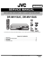
SERVICE MANUAL
DVD VIDEO RECORDER & VIDEO CASSETTE RECORDER
4
2004
YD006
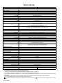
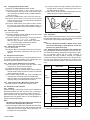
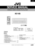
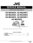
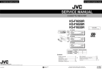
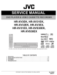
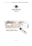
DR-MV1SUC, DR-MV1SUS
CABLE/DBS
VCR
TIMER
TV
DVD
VCR TV/CBL/DBS
/DVD /DVD
DVD
TIMER
NUMBER / TV CH / DVD CH
1
3
2
ABC
DEF
4
5
6
GHI
JKL
MNO
7
8
9
PQRS
TUV
WXYZ
0
CANCEL
AUX
MEMO/MARK
PROG/CHECK DISPLAY ON SCREEN
VCR PLUS+
ION
IGAT
U
NAV
EN
PM
TO
PROGRESSIVE
SCAN
ME
NU
ENTER
SE
TU
T
RE
P
PREVIOUS
SLOW
STOP/ CLEAR
REMAIN
N
UR
NEXT
PLAY/SELECT SLOW
PAUSE
REC
REC MODE
POWER
ANGLE SUBTITLE
LIVE CHECK
TV/VCR
TV/DVD
AUDIO
CH
TV
VOL.
TV/CBL/DVD
TV
VCR/DVD
VCR EJECT
TIMER
VCR
REC
OPEN/CLOSE
STOP
PLAY
TIMER
DVD
REC
VCR
DUBBING
DVD
PULL-OPEN
PULL-OPEN
REMAIN
REC
PAUSE
REW
FF
CH
REC LINK
DV IN
F-1
DVD
S-VIDEO
VIDEO
(MONO) L - AUDIO - R
REC MODE
<< SLOW >>
DVD
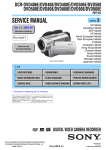
DR-MV1SUC, DR-MV1SUS [D3RV21]
For disassembling and assembling of MECHANISM ASSEMBLY, refer to the SERVICE MANUAL No.86700(MECHANISM ASSEMBLY).
TABLE OF CONTENTS
1
2
3
4
5
PRECAUTION. . . . . . . . . . . . . . . . . . . . . . . . . . . . . . . . . . . . . . . . . . . . . . . . . . . . . . . . . . . . . . . . . . . . . . . . . 1-3
SPECIFIC SERVICE INSTRUCTIONS . . . . . . . . . . . . . . . . . . . . . . . . . . . . . . . . . . . . . . . . . . . . . . . . . . . . . . 1-5
DISASSEMBLY . . . . . . . . . . . . . . . . . . . . . . . . . . . . . . . . . . . . . . . . . . . . . . . . . . . . . . . . . . . . . . . . . . . . . . . 1-7
ADJUSTMENT . . . . . . . . . . . . . . . . . . . . . . . . . . . . . . . . . . . . . . . . . . . . . . . . . . . . . . . . . . . . . . . . . . . . . . . 1-10
TROUBLESHOOTING . . . . . . . . . . . . . . . . . . . . . . . . . . . . . . . . . . . . . . . . . . . . . . . . . . . . . . . . . . . . . . . . . 1-15
COPYRIGHT © 2004 VICTOR COMPANY OF JAPAN, LIMITED
No.YD006
2004/4
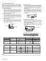
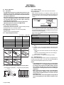
SPECIFICATION
DR-MV1SUC
DR-MV1SUS
GENERAL
Power requirement
AC 120 V, 60 Hz
Power consumption
Power on
43 W
Power off
16.5 W
Temperature
Operating
Storage
Operating position
Dimensions (W × H × D)
Weight
5°C to 35°C (41°F to 95°F)
-20°C to 60°C (-4°F to 140°F)
Horizontal only
435 mm × 96 mm × 347 mm (17-3/16" × 3-13/16" × 13-11/16")
6.1 kg (13.5 lbs)
VIDEO/AUDIO (DVD Deck)
Recording format
Recording time
Audio recording system
Video recording compression system
DVD-RAM: DVD Video Recording format
DVD-R: DVD-Video format
DVD-RW: DVD-Video format, DVD Video Recording format
Maximum 8 hours (with 4.7 GB disc)
(XP): Approx. 1 hour, (SP): Approx. 2 hours, (LP): Approx. 4 hours
(EP): Approx. 6 hours, (FR): Approx. 1 hour - 8 hours
Dolby Digital (2 ch), Linear PCM (XP mode only)
MPEG2 (CBR/VBR)
Input/Output
S-video input
S-video output
Video input
Video output
Audio input
Audio output
i.Link
Component video output
Digital audio output
Y: 0.8 - 1.2 Vp-p, 75 Ω, C: 0.2 - 0.4 Vp-p, 75 Ω
Y: 1.0 Vp-p, 75 Ω, C: 0.3 Vp-p, 75 Ω
0.5 - 2.0 Vp-p, 75 Ω (pin jack)
1.0 Vp-p, 75 Ω (pin jack)
-8 dB, 50 kΩ (pin jack), Corresponding to mono (left)
-8 dB, 1 kΩ (pin jack)
4-pin for DV input
Y: 1.0 Vp-p, 75 Ω, CB/CR, PB/PR: 0.7 Vp-p, 75 Ω
Corresponding to copy protection
Optical: -18 dBm, 660 nm, Coaxial: 0.7 Vp-p, 75 Ω,
Corresponding to Dolby Digital and DTS Digital Surround
Bit stream Selectable in digital audio output setting menu
VIDEO/AUDIO (VCR Deck)
Signal system
Recording system
Format
NTSC color signal and EIA monochrome signal, 525 lines/60 fields
DA4 (Double Azimuth) head helical scan system
VHS NTSC standard
Maximum recording time
(SP)
210 min. with ST-210 video cassette
(EP)
630 min. with ST-210 video cassette
Signal-to-noise ratio
45 dB
Horizontal resolution
230 lines
Frequency range
Input/Output
70 Hz to 10,000 Hz (Normal audio), 20 Hz to 20,000 Hz (Hi-Fi audio)
RCA connectors: IN × 2, OUT × 1
TUNER/TIMER
Tuning system
Channel coverage
RF output
Memory backup time
Frequency synthesized tuner
VHF: Channels 2 - 13, UHF: Channels 14 - 69, CATV: 113 Channels
Channel 3 or 4 (switchable; preset to Channel 3 when shipped) 75 Ω, unbalanced
Approx. 5 seconds
ACCESSORIES
Provided accessories RF cable × 1, Infrared remote control unit, "AA" battery RF cable × 3, Antenna splitter, Infrared remote control
×2
unit, "AA" battery × 2
•
•
•
•
•
Specifications shown are for SP mode unless otherwise specified.
E.& O.E. Design and specifications subject to change without notice.
VCR Plus+, C3 and PlusCode are registered trademarks of Gemstar Development Corporation.
The VCR Plus+ system is manufactured under license from Gemstar Development Corporation.
DSSTM is an official trademark of DIRECTV, Inc., a unit of GM Hughes Electronics. DISH NetworkTM is a trademark of Echostar Communications
Corporation.
• Manufactured under license from Dolby Laboratories. "Dolby" and the double-D symbol are trademarks of Dolby Laboratories.
• "DTS" and "DTS Digital Out" are trademarks of Digital Theater Systems, Inc.
• (i.Link) refers to the IEEE1394-1995 industry specification and extensions thereof. The logo is used for products compliant with the i.Link standard.
1-2 (No.YD006)
SECTION 1
PRECAUTION
1.1
SAFTY PRECAUTIONS
Prior to shipment from the factory, JVC products are strictly inspected to conform with the recognized product safety and electrical codes of the countries in which they are to be
sold.However,in order to maintain such compliance, it is equally
important to implement the following precautions when a set is
being serviced.
1.1.1 Precautions during Servicing
(1) Locations requiring special caution are denoted by labels
and inscriptions on the cabinet, chassis and certain parts of
the product.When performing service, be sure to read and
comply with these and other cautionary notices appearing
in the operation and service manuals.
(2) Parts identified by the symbol and shaded (
) parts
are critical for safety.
Replace only with specified part numbers.
NOTE :
Parts in this category also include those specified to
comply with X-ray emission standards for products
using cathode ray tubes and those specified for
compliance with various regulations regarding spurious radiation emission.
(3) Fuse replacement caution notice.
Caution for continued protection against fire hazard.
Replace only with same type and rated fuse(s) as specified.
(4) Use specified internal wiring. Note especially:
• Wires covered with PVC tubing
• Double insulated wires
• High voltage leads
(5) Use specified insulating materials for hazardous live parts.
Note especially:
• Insulation Tape
• PVC tubing
• Spacers
• Insulation sheets for transistors
• Barrier
(6) When replacing AC primary side components (transformers,
power cords, noise blocking capacitors, etc.) wrap ends of
wires securely about the terminals before soldering.
Consequently, when servicing these products, replace the
cathode ray tubes and other parts with only the specified
parts. Under no circumstances attempt to modify these circuits.Unauthorized modification can increase the high voltage value and cause X-ray emission from the cathode ray
tube.
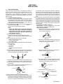
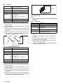
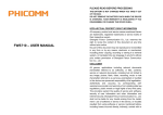
(12) Crimp type wire connectorIn such cases as when replacing
the power transformer in sets where the connections between the power cord and power trans former primary lead
wires are performed using crimp type connectors, if replacing the connectors is unavoidable, in order to prevent safety hazards, perform carefully and precisely according to the
following steps.
• Connector part number :E03830-001
• Required tool : Connector crimping tool of the proper
type which will not damage insulated parts.
• Replacement procedure
a) Remove the old connector by cutting the wires at a
point close to the connector.Important : Do not reuse a connector (discard it).
cut close to connector
Fig.1-1-3
b) Strip about 15 mm of the insulation from the ends
of the wires. If the wires are stranded, twist the
strands to avoid frayed conductors.
15 mm
Fig.1-1-4
c) Align the lengths of the wires to be connected. Insert the wires fully into the connector.
Metal sleeve
Connector
Fig.1-1-1
(7) Observe that wires do not contact heat producing parts
(heatsinks, oxide metal film resistors, fusible resistors, etc.)
(8) Check that replaced wires do not contact sharp edged or
pointed parts.
(9) When a power cord has been replaced, check that 10-15
kg of force in any direction will not loosen it.
Power cord
Fig.1-1-5
d) As shown in Fig.1-1-6, use the crimping tool to crimp
the metal sleeve at the center position. Be sure to
crimp fully to the complete closure of the tool.
1.2
5
2.0
5.5
Fig.1-1-6
e) Check the four points noted in Fig.1-1-7.
Not easily pulled free
Fig.1-1-2
(10) Also check areas surrounding repaired locations.
(11) Products using cathode ray tubes (CRTs)In regard to such
products, the cathode ray tubes themselves, the high voltage circuits, and related circuits are specified for compliance with recognized codes pertaining to X-ray emission.
Crimping tool
Crimped at approx. center
of metal sleeve
Conductors extended
Wire insulation recessed
more than 4 mm
Fig.1-1-7
(No.YD006)1-3
1.1.2 Safety Check after Servicing
Examine the area surrounding the repaired location for damage
or deterioration. Observe that screws, parts and wires have been
returned to original positions, Afterwards, perform the following
tests and confirm the specified values in order to verify compliance with safety standards.
(1) Insulation resistance test
Confirm the specified insulation resistance or greater between power cord plug prongs and externally exposed
parts of the set (RF terminals, antenna terminals, video and
audio input and output terminals, microphone jacks, earphone jacks, etc.).See table 1 below.
(2) Dielectric strength test
Confirm specified dielectric strength or greater between
power cord plug prongs and exposed accessible parts of
the set (RF terminals, antenna terminals, video and audio
input and output terminals, microphone jacks, earphone
jacks, etc.). See Fig.1-1-11 below.
(3) Clearance distance
When replacing primary circuit components, confirm specified clearance distance (d), (d') between soldered terminals, and between terminals and surrounding metallic
parts. See Fig.1-1-11 below.
(4) Leakage current test
Confirm specified or lower leakage current between earth
ground/power cord plug prongs and externally exposed accessible parts (RF terminals, antenna terminals, video and
audio input and output terminals, microphone jacks, earphone jacks, etc.).
Measuring Method : (Power ON)Insert load Z between
earth ground/power cord plug prongs and externally exposed accessible parts. Use an AC voltmeter to measure
across both terminals of load Z. See Fig.1-1-9 and following Fig.1-1-12.
a
Externally
exposed
accessible part
A
V
Fig.1-1-9
(5) Grounding (Class 1 model only)
Confirm specified or lower grounding impedance between
earth pin in AC inlet and externally exposed accessible
parts (Video in, Video out, Audio in, Audio out or Fixing
screw etc.).Measuring Method:
Connect milli ohm meter between earth pin in AC inlet and
exposed accessible parts. See Fig.1-1-10 and grounding
specifications.
d
Chassis
Z
b
c
d'
Power cord
primary wire
Exposed accessible part
AC inlet
Fig.1-1-8
Earth pin
MIlli ohm meter
Grounding Specifications
Region
Grounding Impedance ( Z )
USA & Canada
Z
0.1 ohm
Europe & Australia
Z
0.5 ohm
Fig.1-1-10
AC Line Voltage
100 V
100 to 240 V
Region
Insulation Resistance (R)
Japan
110 to 130 V
USA & Canada
110 to 130 V
200 to 240 V
Europe & Australia
R
1M
1 M /500 V DC
R
R
12 M /500 V DC
10 M /500 V DC
Dielectric Strength
AC 1 kV 1 minute
AC 1.5 kV 1 minute
Clearance Distance (d), (d')
d, d'
3 mm
d, d'
4 mm
AC 1 kV 1 minute
AC 3 kV 1 minute
(Class )
AC 1.5 kV 1 minute
(Class )
d, d'
3.2 mm
d
4 mm
d'
8 m m (Power cord)
d'
6 m m (Primary wire)
Leakage Current (i)
a, b, c
Fig.1-1-11
AC Line Voltage
100 V
Japan
110 to 130 V
USA & Canada
110 to 130 V
220 to 240 V
Load Z
Region
Europe & Australia
i
1 mA rms
Exposed accessible parts
i
0.5 mA rms
Exposed accessible parts
2
i
i
0.7 mA peak
2 mA dc
Antenna earth terminals
50
i
i
0.7 mA peak
2 mA dc
Other terminals
1
0.15
1.5
Fig.1-1-12
NOTE :
These tables are unofficial and for reference only. Be sure to confirm the precise values for your particular country and locality.
1-4 (No.YD006)
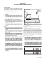
SECTION 2
SPECIFIC SERVICE INSTRUCTIONS
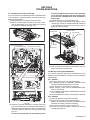
2.1 Service position
This unit has been designed so that the Mechanism and Main
board assemblies can be removed together from the bottom
chassis. Before diagnosing or servicing the circuit boards, take
out the major parts from the bottom chassis.
2.1.1 How to set the "Service position"
(1) Refer to the disassembly procedure and perform the disassembly of the major parts before removing the Mechanism
assembly.
(2) Remove the screws that fix the Mechanism, Main board assembly to the bottom chassis. If any other screws are used
to fix the boards, remove them also.
(3) Remove the combined Mechanism, DVD unit, regulator,
digital, junction and Main board assemblies.
(4) If any other major parts are used, remove them also.
(5) Connect the wires and connectors of the major parts that
have been removed in steps (1) to (4). (Refer to Fig. 2-1a.)
(6) Place the combined Mechanism, Main board and other
board assemblies upside down.
(7) Insert the power cord plug into the power outlet and then
proceed with the diagnostics and servicing of the board assembly.
Notes:
• Before inserting the power cord plug into the power outlet, make sure that none of the electrical parts are able
to short-circuit between the workbench and the board
assembly.
• For the disassembly procedure of the major parts and
details of the precautions to be taken, see "Removing
the major parts".
• If there are wire connections from the Main board and
Mechanism assemblies to the other major parts, be sure
to remove them (including wires connected to the major
parts) first before performing step (2).
• When carrying out diagnosis and repair of the Main
board assembly in the "Service position", be sure to
ground both the Main board and Mechanism assemblies. If they are improperly grounded, there may be
noise on the playback picture or FDP counter display
may move even when the mechanism is kept in an inoperative status.
• In order to diagnose the playback or recording of the
cassette tape, set the Mechanism assembly to the required mode before placing it upside down. If the mechanism mode is changed (including ejection) while it is in
an upside down position the tape inside may be damaged.
• For some models, the mechanism and board assemblies are attached by connectors only. When carrying
out a diagnosis or repair of the boards in the "Service
position", make sure that the connectors are not disconnected.
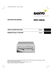
Main board assy
Regulator board assy
TP111 D.FF
TP106 PB FM
TP2253 A.PB FM
TP4001 CTL.P
Junction
board
assy
Digital
board
assy
Jack
board
assy
Switch display board assy
Operation jack board assy
Fig.2-1a
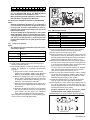
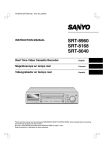
2.2 Jig RCU mode
This unit uses the following two modes for receiving remote control codes.
(1) User RCU mode:Ordinary mode for use by the user.
(2) Jig RCU mode: Mode for use in production and servicing.
When using the Jig RCU, it is required to set the VCR to the Jig
RCU mode (the mode in which codes from the Jig RCU can be
received). As both of the above two modes are stored in the EEPROM, it is required to set the VCR back to the User RCU mode
each time that an adjustment is made or to check that the necessary operations have been completed.These modes can be set
by the operations described below.
Note:
• When the unit is set to JIG mode and when the unit is
under JIG mode, the remote control unit attached to
product operates only in "Remote Control Code 1".
Since the unit is in "Remote Control Code 3" when it is
shipped and just after its batteries are changed, "Remote Control Code 3" needs to be changed to "Remote
Control Code 1."
• Confirm the RCU mode when exchanged parts. Since
some SERVICE PARTS sets the VCR to the Jig RCU
mode as initial setting. Therefore please set the VCR to
the user RCU mode after replacing the EEPROM.
User RCU mode
Jig RCU mode
( blinked)
Fig.2-2a User/Jig RCU mode
(No.YD006)1-5
2.2.1 Changing Remote Control Code
(1) Slide the TV/CABLE/DBS/DVD switch to DVD.
(2) Press the numeric button "1" of the remote control unit
while pressing the "SET UP" button of the remote control
unit. Then,press the "ENTER" button, and then release the
"SET UP" button.
(3) Press the "POWER" button on the unit to turn off the unit.
(4) Press the "PLAY" button on the unit for over 5 seconds
while the unit is turned off. The code currently set appears
on the front display panel.
(5) Press the "STOP" button on the remote control to change
the unit’s code. When FDP indicator displays "DVD1," it
means that the Remote Control Code has been changed to
"1."
2.2.2 Setting the Jig RCU mode
(1) Turn on the power.
(2) Press the “VCR/DVD“ button repeatedly on the unit so that
the VCR lamp lights up on the unit.
(3) Press the following remocon keys continuously within 2
seconds " SET UP " → " 2 " → " 8 " → " ENTER ".
When the VCR is set to the Jig RCU mode, the symbols
( " : " ) in the time display of the FDP are blinked.
(Refer to Fig.2-2a User/Jig RCU mode)
2.2.3 Setting the User RCU mode
(1) Turn off the power.
(2) Press the "REC" and "PAUSE" buttons of the VCR simultaneously. Alternatively, transmit the code "9D" from the
Jig RCU.
2.3
Mechanism service mode
This model has a unique function to enter the mechanism into every operation mode without loading of any cassette tape. This
function is called the "Mechanism service mode".
2.3.1 How to set the "Mechanism service mode"
(1) Set the VCR to the Jig RCU mode (the mode in which
codes from the Jig RCU can be received)
(2) Transmit the code "E5" from the Jig RCU.
(3) Release the lug of the Cassette holder and then slide the
Cassette holder toward the direction where the Cassette
holder is loaded by manually.
(4) The cassette holder lowers and, when the loading has
completed, the mechanism enters the desired mode.
When the VCR is set to the Mechanism service mode, the
symbols ("HDD") in the FDP (LED) are turned on.
(2) To clean the parts of the tape transport system other than
the upper drum, use a piece of closely woven cloth or a cotton swab soaked with alcohol.
(3) After cleaning, make sure that the cleaned parts are completely dry before using the cassette tape.
A/C head
Fig.2-4a
2.4.2 Lubrication
With no need for periodical lubrication, you have only to lubricate
new parts after replacement. If any oil or grease on contact parts
is soiled, wipe it off and newly lubricate the parts.
Note:
• See the "mechanism assembly" diagram of the "parts
list" for the lubricating or greasing spots, and for the
types of oil or grease to be used.
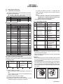
2.4.3 Suggested servicing schedule for main components
The following table indicates the suggested period for such service measures as cleaning, lubrication and replacement. In practice, the indicated periods will vary widely according to
environmental and usage conditions. However, the indicated
components should be inspected when a set is brought for service and the maintenance work performed if necessary. Also
note that rubber parts may deform in time, even if the set is not
used.
System
Tape
transport
2.3.2 How to exit from the "Mechanism service mode"
(1) Unplug the power cord plug from the power outlet.
2.4
Maintenance and inspection
2.4.1 Cleaning
Regular cleaning of the transport system parts is desirable but
practically impossible. So make it a rule to carry out cleaning of
the tape transport system whenever the machine is serviced.
When the video head, tape guide and/or brush get soiled, the
playback picture may appear inferior or at worst disappear, resulting in possible tape damage.
Note:
• Absolutely avoid sweeping the upper drum vertically as
this will cause damage to the video head.
(1) When cleaning the upper drum (especially the video head),
soak a piece of closely woven cloth with alcohol and while
holding the cloth onto the upper drum by the fingers, turn
the upper drum counterclockwise.
1-6 (No.YD006)
Video heads
Drive
Other
Parts name
Operation hours
1000H
2000H
Drum assembly
C,X
X
A/C head
C,X
C,X
Pinch roller arm assembly
C
C
Full erase head
C
C
Tension arm assembly
C
C
Capstan motor (Shaft)
C
C
Guide arm assembly
C
C
Capstan motor
X
Capstan brake assembly
X
Main brake assembly
X
Belt (Capstan)
X
X
Loading motor
X
Clutch unit
X
Worm gear
X
Control plate
X
Rotary encoder
X
C : Cleaning
X : Inspection or Replacement if necessary
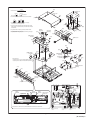
SECTION 3
DISASSEMBLY
3.1
Removing the major parts
3.1.1 Destination of connectors
Two kinds of double-arrows in connection tables respectively
show kinds of connector/wires.
: Flat wire
: Wire
: Board to board (B-B)
: The connector of the side to remove
CONN. No.
CONNECTOR
PIN No.
WR2a
Main
CN101
Digital
CN761
40
WR2b
Main
CN103
Digital
CN762
10
Destination of connectors
CONN. No.
CONNECTOR
PIN No.
WR2a
Main
CN3104
Operation jack CN7201
13
WR2b
Main
CN3102
Switch display CN7001
11
WR2c
Junction CN7103
Switch display CN7002
4
WR3a
Main
A/C head
6
WR3b
Drum
assembly
Main
WR4a
DVD unit
WR4b
DVD unit
WR5a
CN2001
CN1
9
Digital
CN2201
40
Regulator
CN5303
4
Junction CN7106
Digital
CN1404
4
CN7108
Junction CN7108
(CN1001)
Digital
CN1001
28
CN7109
Junction CN7109
(CN1002)
Digital
CN1002
28
CN4104
Jack
(CN1801)
Digital
CN1801
10
CN501
4
CN4104
WR7a
Junction CN7104
Main
WR7b
Main
CN3103
Junction
CN7102
15
WR7c
Main
CN2601
Junction
CN8001
11
WR7d
Junction CN7107
Main
CN7111
13
WR7e
Regulator CN5304
Junction
CN5501
15
WR8a
Regulator CN5301
Main
CN5311
15
WR8b
Regulator CN5302
Fun motor
2
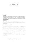
3.1.2 How to read the procedure table
This table shows the steps for disassembly of the externally furnished parts and board assemblies. Reverse these steps when
re-assembling them.
Step/
Loc No.
[1]
Part Name
Top cover
Bracket
(1)
(2)
Fig.
No.
Point
Note
3-1a 4(S1a),(S1b),3(L1a), <Note 1a>
2(SD1a),(P1a),(W1a),
CN1(WR1a),
---------------------------------------2(S1c)
(3)
(4)
P= Spring, W= Washer, S= Screw, L= Locking tab, SD=
Solder, CN**(WR**)= Remove the wire (WR**) from the
connector (CN**).
Note:
• The bracketed ( ) WR of the connector symbol are
assigned nos. in priority order and do not correspond to those on the spare parts list.
(5) Adjustment information for installation
3.1.3 Disassembly procedure
Step/
Part Name
Loc No.
[1] Top cover
[2] Front panel assembly
(Operation jack board assembly)
(Switch display board assembly)
Fig.
Point
No.
3-1d 6(S1a)
3-1a, 3(L2a),5(L2b)
3-1d CN3104(WR2a)
CN3102(WR2b)
CN7103(WR2c)
[3] Mechanism assembly
3-1b, CN2001(WR3a)
3-1c, 3(S3a),(S3b)
3-1d CN(WR3b)
(Drum assembly)
(S3c),(S3d),(S3e)
2(L3a)
(Cleaner assembly)
[4] DVD unit
3-1d 4(S4a),4(S4b)
(WR4a),(WR4b)
(Bracket)
[5] Digital board assembly
3-1d 4(S5a)
CN7106(WR5a),CN7101
(CN1001),CN7109(CN1002)
[6] Jack board assembly
3-1d (S6a),CN4104(CN1801)
[7] Junction board assembly 3-1d (S7a),CN7104(WR7a),
CN3103(WR7b),CN2601
(WR7c),CN7107(WR7d),
CN5304(WR7e)
[8] Regulator board assembly 3-1d 4(S8a)
CN5301(WR8a),
CN5302(WR8b)
[9] Rear cover
3-1d 2(S9a),5(S9b),2(S9c),3(L9a)
[10] Main board assembly
3-1d 3(S10a)
Note
<Note2a>
<Note2b>
<Note2a>
<Note3a>
<Note3b>
<Note3c>
<Note2a>
<Note2a>
<Note2a>
<Note2a>
<Note 2a>
• Be careful not to damage the connector and wire etc. during
connection and disconnection.
• When connecting the flat wire to the connector, be careful with
the flat wire direction.
<Note 2b>
• When reattaching the Front panel assembly, make sure that
the door opener of the Side frame (R) is lowered in position prior to the reinstallation.
• When reattaching the Front panel assembly, pay careful attention
to the switch lever of the Front panel assembly not to make it
touch the switch knob of the Main board assembly from the side.
• When reattaching the Front panel assembly, lift the Cassette
door slightly.
(5)
(1) Order of steps in Procedure
When reassembling, perform the step(s) in the reverse order.
These numbers are also used as the identification (location) No. of parts Figures.
(2) Part name to be removed or installed.
(3) Fig. No. showing procedure or part location.
(4) Identification of part to be removed, unhooked, unlocked,
released, unplugged, unclamped or unsoldered.
Door
opener
Side
frame(R)
Switch
knob
Switch
lever
Fig.3-1a
(No.YD006)1-7
<Note 3a>
• When reattaching the Mechanism assembly, secure the
screws (S3a to S3b) in the order of 1,2,3.
<Note 3b>
• When reattaching the Mechanism assembly, be sure to align
the phase of the Rotary encoder on the Main board assembly.
• When reattaching the Mechanism assembly, set the “Mechanism assembling mode”. [See “MECHANISM ASSEMBLY
SERVICE MANUAL (No. 86700)”.]
• When reattaching the Mechanism assembly to the Main board
assembly, take care not to damage the sensors and switch on
the Main board assembly.
<Note 3c>
• When reattaching the Drum assembly, secure the screws (S3c
to S3e) in the order of c, d, e.
(S3d)
(S3c)
(S3e)
(S3e)
Mechanism
assembly
(S3d)
Drum
assembly
<Note 3c>
(S3c)
HOOK
<NOTE>
Attach the Drum assembly appropriately,
since the installation state of the Drum assembly
influences the FM WAVEFORM LINEARITY
greatly.
Fig.3-1b
• When handling the drum assembly alone, hold it by the motor
or shaft. Be careful not to touch other parts, especially the video heads. Also take care not to damage the connectors.
Shaft
Motor
Video heads
Fig.3-1c
1-8 (No.YD006)
NOTE
(S1a)
[4]DVD unit
1.Insert direction of FCC WIRE as follows.
right side
[1]Top cover
back side
supporting side
electrode side
(S1a)
2.FFC WIRE and DRUM FPC WIRE should be insert as follows.
(S1a)
NG
OK
(S1a)
90
CN
CN
[4]Bracket
CN
3.Insert the wire to even the root of connector completely
at the same time as inserting each wire.
(S4a)
b
(S4a)
4.Check to see that outside parts.TOP COVER,BOTTOM COVER,
FRONT PANEL, etc are fixed certainly to the BOTTOM CHASSIS
with SCRWES.
(S1a)
(S4b)
b
(S9c)
5.Pay attention NOT to make any scratches on FRONT PANEL.
[3]Drum
assembly
6.Pay close attention not to cut any Sheath of WIRE by sharp edge
of CHASSIS while Wireing Process.
(S3a)
(S4a)
b
(S4b)
(S9b)
[3]Cleaner
assembly
(S4a)
b
(S4b)
(S4b)
(S9b)
(S9b)
(S9a)
(L9a)
q
[3]Mechanism
assembly
f
(S3a)
[9]Rear cover
(S3a)
j
(L9a)
j
(S3b)
g
(L9a)
h
(S5a)
(S10a)
r
(S3c)
(S3e)
(S3d)
(S5a)
(S5a)
e'
(S10a)
[10]Main board
assembly
e'
e'
[5]Digital board
assembly
JS3001
JS
30
(S5a)
(S6a) (S8a)
[6]Jack board
assembly
01
(S8a)
e'
f
c
k
(S8a)
m
<Phase alignment>
. Accord the position of V gap on R.ENCORDER and PWB silk
. Accord the position of Boss on R.ENCORDER and PWB silk
(S10a)
c
CN
(S7a)
a
c
e'
e'
c
e
e'
[8]Regulator board
assembly
e'
(L2b)
e
d
[7]Junction board
assembly
e
(L2a)
01
(S8a)
e
i
50
i c
e
d
(L2a)
g
c
b
h
c
(L2a)
c
b
e
Cassette door
<Note2b>
[2]Front panel
assembly
e
b
e
d
d
k
e
b
m
(L2b)
(L2b)
i
e
a
JACK BOARD ASSY
(WR8b)
FW7504
FAN
CN8501
CN5001
CN7111
CN5302
(WR2c)
<Note2a>
(WR2b)
<Note2a>
CN501
CN2001
SWITCH DISPLAY
BOARD ASSY
REGULATOR BOARD ASSY
(WR4b)
<Note2a>
(WR8a)
<Note2a> CN5304
(WR7e)
CN3106
OPERATION JACK
BOARD ASSY
(WR3b)
<Note2a>
CN5311
BOTTOM SIDE
CN5301
MAIN BOARD ASSY
(WR2a)
<Note2a>
(WR7d)
<Note2a>
CN5501 JUNCTION
CN7107
BOARD ASSY
(WR7c)
<Note2a>
CN1404
DVD
UNIT
CN2201
CN7102
NOTE)Push the slack of the wire
into the FW7001 side.
CN3103
(WR3a)
<Note2a>
CN7106
A/C HEAD
CN8001
CN7002
CN7001
CN2601
CN7002
CN7201
CN7001
(WR5a)
<Note2a>
(WR4a)
<Note2a>
CN7104
NOTE)Pass slit PCB through wire.
CN3104
TOP SIDE
(WR7b)
<Note2a> CN3102
(WR7a)
<Note2a>
DIGITAL
BOARD ASSY
CN7103
NOTE) INSERT FFC WIRE TO THE CONNECTOR BEFORE ATTACHING TO FRONT PANEL.
Operation jack assembly
CN7201
Switch display assembly
CN7001
Switch display assembly
CN7002
Fig.3-1d
(No.YD006)1-9
SECTION 4
ADJUSTMENT
4.1
Before adjustment
4.1.1 Precaution
• The adjustments of this unit include the mechanism compatibility and electrical adjustments. During the performance of this work, be sure to observe the precautions for
each type of adjustment.
• If there is a reference to a signal input method in the signal
column of the adjustment chart, “Ext. S-input” means the
Y/C separated video signal and “Ext. input” means the
composite video signal input.
• Unless otherwise specified, all measuring points and
adjustment parts are located on the Main board.
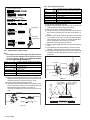
4.1.2 Required test equipments
• Color (colour) television or monitor
• Oscilloscope: wide-band, dual-trace, triggered delayed sweep
• Signal generator: RF / IF sweep / marker
• Signal generator: stairstep, color (colour) bar [NTSC]
• Recording tape
• Digit-key remote controller(provided)
4.1.3 Required adjustment tools
z : Used --- : Not used
Mechanism
compatibility
adjustment
Electrical
adjustment
Roller driver
z
---
Jig RCU
---
z
Back tension cassette gauge
z
---
Alignment tape(MHP)
z
---
Alignment tape(MHP-L)
z
z
Roller driver
PTU94002
Jig RCU
PTU94023B
Alignment tape
(SP, stairstep, NTSC)
MHP
Alignment tape
(EP, stairstep, NTSC)
MHP-L
Back tension cassette gauge
PUJ48076-2
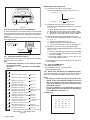
Color(colour) bar pattern [NTSC]
1V
40 IRE
40 IRE
Q
Horizontal sync
1-10 (No.YD006)
I
Q
White
100%
I
Black
Blue
Red
Magenta
Cyan
Green
White
Burst
Yellow
100 IRE
(75%)
Cyan
Green
Magenta
Red
Blue
White(75%)
Yellow
White(100%)
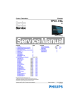
Jig RCU
[Data transmitting method]
Depress the " "( 3 ) button
after the data code is set.
INITIAL MODE
CUSTOM CODE
43: A CODE
DATA CODE
Fig.4-1 Jig RCU [PTU94023B]
• Set the switches as shown below unless otherwise specified
on the relevant adjustment chart. The switches that are not listed below can be set as desired.
If the VCR is not equipped with the functions detailed below,
setup is not required.
AUTO PICTURE/VIDEO CALIBRATION/
B.E.S.T./D.S.P.C.
PICTURE CONTROL/SMART PICTURE
VIDEO STABILIZER
TBC
Digital 3R
VIDEO NAVIGATION/TAPE MANAGER
BLUE BACK
OFF
NORMAL/NATURAL
OFF
ON
ON
OFF
OFF
4.1.6 Manual tracking mode (Auto tracking ON/OFF) setting
(1) In order to set to the manual tracking mode during tape
playback, press the “SP/EP(LP)”button on the remote control unit.
• Each press of the button switches the auto tracking ON
or OFF.
• When the manual tracking mode is set, the tracking is
placed at the center position.
(2) Press “channel +/-” to adjust the tracking manually.
4.1.7 EVR Adjustment
Some of the electrical adjustments require the adjustment performed by the EVR system. The main unit have EEPROMs for
storing the EVR adjustment data and user setups.
4.1.4 Color (colour) bar signal,Color (colour) bar pattern
Color(colour) bar signal [NTSC]
4.1.5 Switch settings
When adjusting this unit, set the VCR mode and switches
as described below.
• When using the Jig RCU, it is required to set the VCR to the
Jig RCU mode (the mode in which codes from the Jig RCU can
be received). (See "section 2 SPECIFIC SERVICE INSTRUCTIONS".)
Notes:
• In the EVR adjustment mode, the value is varied with the
channel buttons (+, -). The adjusted data is stored when
the setting mode changes (from PB to STOP, when the
tape speed is changed, etc.). Take care to identify the
current mode of each adjustment item when making an
adjustment.
• When changing the address setting in the EVR adjustment mode, use the Jig RCU or the remote controller
having numeric keypad with which a numeric code can
be directly input.
The remote control code of the Jig RCU corresponds to
each of the digit keys on the remote controller as follows.
Digit-key
Code
0
20
1
21
2
22
3
23
4
24
5
25
6
26
7
27
8
28
9
29
• As the counter indication and remaining tape indication
are not displayed FDP during the EVR adjustment
mode, check them on the TV monitor screen.
• When performing the EVR adjustment, confirm that the
FDP indication is changed to the EVR mode.
TENSION ARM
CONTROL PLATE
Stamping(a)
Stamping(b)
OK
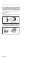
4.2 Mechanism compatibility adjustment (VHS SECTION)
Notes:
• Although compatibility adjustment is very important, it
is not necessary to perform this as part of the normal
servicing work. It will be required when you have replaced the A/C head, drum assembly or any part of the
tape transport system.
• To prevent damaging the alignment tape in the compatibility adjustment, prepare a cassette tape (for self-recording/playback), perform a test on it by transporting it
and making sure that the tape is not bent by the tape
transport mechanisms such as in the guide rollers.(See
Fig.4-2b.)
4.2.1 Tension pole position
Notes:
• This adjustment must be performed every time the tension band is replaced.
Signal
(A)
Mode
(B1) • PB
(B2) • Eject end
• Back tension cassette gauge [PUJ48076-2]
Adjustment part (F)
• Adjust pin [Mechansim assembly]
Specified value (G)
• 25 - 51 gf•cm (2.45 - 5 x 10⁻³ Nm)
(1) Play back the back tension cassette gauge (A).
(2) Check that the indicated value on the left side gauge is
within the specified value (G).
(3) If the indicated value is not within the specified value (G),
perform the adjustment in a following procedure.(See
Fig.4-2a.)
a) Remove the top frame, cassette holder and side
frames (L/R) all together. (Refer to the SERVICE
MANUAL No.86700 [MECHANISM ASSEMBLY].)
b) Rotate the loading motor gear to move the control
plate so that the triangular stamping to the left of the
“P”stamping is aligned with the stamping (a) on the
main deck. This positioning is mode (B1).
c) Adjust by turning the adjustment pin so that the tip of
the tension arm is aligned with the stamping (b) on
the main deck.
d) Rotate the reel disk (S) by about one turn clockwise
and make sure that the round hole of the adjustment
pin is located in the “OK” range. If it is outside this
range, restart the adjustment from the beginning.
After completion of the adjustment, rotate the loading gear
motor to return it to the mode (B2) position.
ADJUST PIN
NG
Fig.4-2a
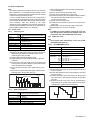
4.2.2 FM waveform linearity
Signal
Mode
Equipment
Measuring point
External trigger
Adjustment part
Specified value
Adjustment tool
(A1)
(A2)
(B)
(C)
(D)
(E)
(F)
(G)
(H)
•
•
•
•
•
•
•
•
•
Alignment tape(SP, stairstep, NTSC) [MHP]
Alignment tape(EP,stairstep,NTSC) [MHP-L]
PB
Oscilloscope
TP106 (PB. FM)
TP111 (D.FF)
Guide roller [Mechanism assembly]
Flat V.PB FM waveform
Roller driver [PTU94002]
(1) Play back the alignment tape (A1).
(2) Apply the external trigger signal to D.FF (E), to observe
the V.PB FM waveform at the measuring point (D).
(3) Set the VCR to the manual tracking mode.
(4) Make sure that there is no significant level drop of the V.PB
FM waveform caused by the tracking operation, with its
generally parallel and linear variation ensured. Perform the
following adjustments when required. (See Fig. 4-2c.)
(5) Reduce the V.PB FM waveform by the tracking operation.
If a drop in level is found on the left side, turn the guide roller of the pole base assembly (supply side) with the roller
driver to make the V.PB FM waveform linear.
If a drop in level is on the right side, likewise turn the guide
roller of the pole base assembly (take-up side) with the
roller driver to make it linear. (See Fig. 4-2c.)
(6) Make sure that the V.PB FM waveform varies in parallel
and linearly with the tracking operation again. When required, perform fine-adjustment of the guide roller of the
pole base assembly (supply or take-up side).
(7) Unload the cassette tape once, play back the alignment
tape (A1) again and confirm the V.PB FM waveform.
(8) After adjustment, confirm that the tape wrinkling does not
occur at the roller upper or lower limits. (See Fig. 4-2b.)
[Perform adjustment step (9) only for the models equipped
with SP mode and EP (or LP) mode.]
[Perform adjustment step (9) only for the models
equipped with SP mode and EP (or LP) mode.]
(9) Repeat steps (1) to (8) by using the alignment tape (A2).
Improper
Proper
(a) GUIDE ROLLER
(b) GUIDE POLE
Fig.4-2b
(No.YD006)1-11
4.2.4 A/C head phase (X-value)
Proper waveform variation
Signal
Mode
Equipment
Measuring point
External trigger
Adjustment part
Specified value
Adjustment tool
A
B
C
D
Roller driver
Guide roller
(supply side)
Fig.4-2c
4.2.3 Height and tilt of the A/C head
Note:
• Set a temporary level of the height of the A/C head in advance to make the adjustment easier after the A/C head
has been replaced. (Refer to the SERVICE MANUAL
No.86700 [MECHANISM ASSEMBLY].)
Signal
Mode
Equipment
Measuring point
(A)
(B)
(C)
(D1)
(D2)
External trigger (E)
Adjustment part (F)
Specified value (G)
•
•
•
•
•
•
•
•
Alignment tape(SP, stairstep, NTSC) [MHP]
PB
Oscilloscope
TP106 (PB. FM)
TP4001 (CTL. P)
TP111 (D.FF)
A/C head [Mechanism assembly]
Maximum waveform
(1) Play back the alignment tape (A).
(2) Apply the external trigger signal to D.FF (E), to observe the
AUDIO OUT waveform and Control pulse waveform at the
measuring points (D1) and (D2) in the ALT mode.
(3) Set the VCR to the manual tracking mode.
(4) Adjust the AUDIO OUT waveform and Control pulse waveform by turning the screws (1), (2) and (3) little by little until
both waveforms reach maximum. The screw (1)
and (3) are for adjustment of tilt and the screw (2) for azimuth.
Head base
AUDIO OUT
Alignment tape(SP, stairstep, NTSC) [MHP]
Alignment tape(EP,stairstep,NTSC) [MHP-L]
PB
Oscilloscope
TP106 (PB. FM)
TP111 (D.FF)
A/C head base [Mechanism assembly]
Flat V.PB FM waveform
Roller driver [PTU94002]
To the drum
Roller driver
Toward the capstan
Screw (4)
Head base
Toward the drum
A/C head
Screw (5)
To the capstan
Fig.4-2e
(2)
(1)
•
•
•
•
•
•
•
•
•
(1) Play back the alignment tape (A1).
(2) Apply the external trigger signal to D.FF (E), to observe the
V.PB FM waveform at the measuring point (D).
(3) Set the VCR to the manual tracking mode.
(4) Loosen the screws (4) and (5), then set the Roller driver to
the innermost projected part of the A/C head. (See Fig. 42e.)
(5) Rotate the roller driver so that the A/C head comes closest
to the capstan. From there, move the A/C head back gradually toward the drum until the point where the FM waveform is maximized for the second time, and then
tighten the screws (4) and (5) temporarily.
(6) Play an alignment tape (A2) and set to the manual-tracking
mode.
(7) Fine-adjust A/C head base position to maximize the FM
waveform, and then tighten the screws (4) and (5) firmly.
(8) Play alignment tapes (A1) and (A2) and confirm that the FM
waveforms are maximized when the tracking is at the center position.
Waveform output
Improper waveform variation
Up
Down
(A1)
(A2)
(B)
(C)
(D)
(E)
(F)
(G)
(H)
Alignment tape
[SP, stairstep]
played with the
SP head
Alignment tape
[EP(LP), stairstep]
played with the
EP(LP) head
X-value adjustment point
Drum side
Control head position
Capstan side
CTL.P
A/C head
Maximum
(3)
Fig.4-2d
1-12 (No.YD006)
Fig.4-2f
4.3 Electrical adjustment
Note:
The following adjustment procedures are not only necessary
after replacement of consumable mechanical parts or board
assemblies, but are also provided as references to be referred
to when servicing the electrical circuitry.
In case of trouble with the electrical circuitry, always begin a
service by identifying the defective points by using the measuring instruments as described in the following electrical adjustment procedures. After this, proceed to the repair,
replacement and/or adjustment. If the required measuring instruments are not available in the field, do not change the adjustment parts (variable resistor, etc.) carelessly.
4.3.1 Servo circuit
4.3.1.1
Switching point
Signal
(A1)
(A2)
Mode
(B)
Equipment
(C)
Measuring point (D)
External trigger
Adjustment part
Specified value
Adjustment tool
•
•
•
•
•
•
•
•
•
•
(E)
(F)
(G)
(H)
Stairstep signal
Alignment tape(EP,stairstep,NTSC) [MHP-L]
PB
Oscilloscope
VIDEO OUT terminal (75 ohm terminated)
TP106 (PB. FM)
TP111 (D.FF)
Jig RCU: Code “5A”
6.5 ± 0.5H
Jig RCU [PTU94023B]
(1) Play back the signal (A1) of the alignment tape (A2).
(2) Apply the external trigger signal to D.FF (E) to observe the
VIDEO OUT waveform and V.PB FM waveform at the
measuring points (D1) and (D2).
(3) Set the VCR to the manual tracking mode.
(4) Adjust tracking so that the V.PB FM waveform becomes
maximum.
(5) Set the VCR to the Auto adjust mode by transmitting the
code (F) from the Jig RCU. When the VCR enters the stop
mode, the adjustment is completed.
(6) If the VCR enters the eject mode, repeat steps (1) to (5)
again.
(7) Play back the alignment tape (A2) again, confirm that the
switching point is the specified value (G).
Trigger point
V.sync
Switching point
(1) Record the signal (A2) in the mode (B1), and play back
the recorded signal.
(2) Set the VCR to the manual tracking mode.
(3) Set the VCR to the FWD slow (+1/6x) mode.
(4) Transmit the code (F) from the Jig RCU to adjust so that the
noise bar becomes the specified value (G) on the TV
monitor in the slow mode.
(5) Set the VCR to the Stop mode.
(6) Confirm that the noise bar is (G) on the TV monitor in the
slow mode.
(7) Repeat steps (3) to (6) in the REV slow (+1/6x) mode.
(8) Repeat steps (1) to (7) in the mode (B2).
Note:
• For FWD slow (+1/6x) playback, transmit the code “08”
from the Jig RCU to enter the slow playback mode, and
transmit the code “D0”for REV slow (-1/6x) mode.
4.3.2 DVD Video circuit
Note
• when perform these adjustments, set the unit to DVD
mode.(DVD lamp lights up)
4.3.2.1
EE COMPONENT Y level
Signal
(A)
• Internal color bar
Mode
(B)
• EE
Equipment
(C)
• Oscilloscope
Measuring point (D)
• COMPONENT Y terminal
EVR mode
EVR address
•
•
•
•
•
(F1)
(F2)
(F3)
(F4)
(F5)
Jig code “95”
"ADJUST01 : **"
Jig code “21”
Jig code “18” or “19” (Channel +/-)
Jig code “3C”
Specified value (G)
• 1.00 ± 0.02 Vp-p (terminated)
Adjustment tool (H)
• Jig RCU [PTU94023B]
(1) Observe the Y OUT waveform at the measuring point (D).
(2) Set the VCR to the EVR mode by transmitting the code (F1)
from the Jig RCU.
(3) Set the EVR address to (F2) by transmitting the code (F3)
from the Jig RCU.
(4) Transmit the code (F4) from the Jig RCU to adjust so that
the Y level of the Y OUT waveform becomes the specified
value (G).
(5) Release the EVR mode of the VCR by transmitting the
code (F5) from the Jig RCU again. (When the EVR mode
is released, the adjusted data is memorized.)
V. rate
Fig.4-3a Switching point
4.3.1.2
Slow tracking preset
Signal
Mode
Measuring point
Adjustment part
Specified value
Adjustment tool
(A1)
(A2)
(B1)
(B2)
(D)
(F)
(G)
(H)
•
•
•
•
•
•
•
•
Ext. input
Color (colour) bar signal [NTSC]
VHS SP
VHS EP
TV-Monitor
Jig RCU: Code “71”or “72”
minimum noise
Jig RCU [PTU94023B]
Y level
Fig.4-3b EE componet Y level
(No.YD006)1-13
4.3.2.2
EE Y level
Signal
(A1) • Ext. input
(A2) • Color (colour) bar signal
Mode
(B)
• EE
Equipment
(C)
• Oscilloscope
PB/CB level
Measuring point (D)
• Y OUT (S terminal)
EVR mode
EVR address
•
•
•
•
•
(F1)
(F2)
(F3)
(F4)
(F5)
Jig code “95”
"ADJUST02 : **"
Jig code “22”
Jig code “18” or “19” (Channel +/-)
Jig code “3C”
Specified value (G)
• 1.00 ± 0.02 Vp-p (terminated)
Adjustment tool (H)
• Jig RCU [PTU94023B]
Y level
H. rate
Fig.4-3c EE Y level
EE COMPONENT PB/CB level
Signal
(A)
• Internal color bar
Mode
(B)
• EE
Equipment
(C)
• Oscilloscope
Measuring point (D)
• COMPONENT PB/CB terminal
EVR mode
EVR address
•
•
•
•
•
(F1)
(F2)
(F3)
(F4)
(F5)
Jig code “95”
"ADJUST06 : **"
Jig code “26”
Jig code “18” or “19” (Channel +/-)
Jig code “3C”
Specified value (G)
• 0.70 ± 20 Vp-p (terminated)
Adjustment tool (H)
• Jig RCU [PTU94023B]
(1) Observe the CB OUT waveform at the measuring point (D).
(2) Set the VCR to the EVR mode by transmitting the code (F1)
from the Jig RCU.
(3) Set the EVR address to (F2) by transmitting the code (F3)
from the Jig RCU.
(4) Transmit the code (F4) from the Jig RCU to adjust so that
the CB level of the CB OUT waveform becomes the specified value (G).
(5) Release the EVR mode of the VCR by transmitting the
code (F5) from the Jig RCU again. (When the EVR mode
is released, the adjusted data is memorized.)
1-14 (No.YD006)
Notes:
• When perform this adjustment, remove the Mechanism
assembly.
4.3.3.1
(1) Observe the Y OUT waveform at the measuring point (D).
(2) Set the VCR to the EVR mode by transmitting the code (F1)
from the Jig RCU.
(3) Set the EVR address to (F2) by transmitting the code (F3)
from the Jig RCU.
(4) Transmit the code (F4) from the Jig RCU to adjust so that
the Y level of the Y OUT waveform becomes the specified
value (G).
(5) Release the EVR mode of the VCR by transmitting the
code (F5) from the Jig RCU again. (When the EVR mode
is released, the adjusted data is memorized.)
4.3.2.3
Fig.4-3d EE component PB/CB level
4.3.3 Syscon circuit
Timer clock
Signal
Mode
Equipment
Measuring point
(A)
(B)
(C)
(D1)
(D2)
(D3)
Adjustment part (F)
Specified value (G)
•
•
•
•
•
•
•
•
No signal
EE
Frequency counter
IC3001 pin 61
IC3001 pin 24
C3026 + and C3025 (TIMER CLOCK)
1024.008 ± 0.001 Hz
(976.5549 ± 0.0010 usec)
(1) Connect the frequency counter to the measuring point
(D1).
(2) Connect the short wire between the short point (D2) and
Vcc (5V).
(3) Short the leads of capacitor (D3) once in order to reset
the microprocessor of the Syscon.
(4) Disconnect the short wire between the short point (D2)
and Vcc then connect it again.
(5) Adjust the Adjustment part (F) so that the output frequency
becomes the specified value (G).
SECTION 5
TROUBLESHOOTING
5.1
Manually removing the cassette tape
If you cannot remove the cassette tape which is loaded because
of any electrical or mechanical failures, manually remove it by
taking the following steps.
(1) Unplug the power cord plug from the power outlet.
(2) Refer to the disassembly procedure of the VCR and perform the disassembly of the major parts before removing
the mechanism assembly. (See Fig. 5-1a)
sion arm assembly free from tension, pull out the tape
on the pole base assembly. Take the spring(a) of the
pinch roller arm assembly off the hook, and detach it
from the tape.
(4) Remove the screw (a) of the side frame (L/R).
(5) Hold the slack tape and cassette cover together, lift the
cassette tape, top frame, cassette holder and side frames
(L, R) together from the rear and remove them by dis-engaging the hooks (a) and (b).
Screw(a)
Cassette tape
Cassette holder
Top frame
Side frame(R)
Screw(a)
Fig.5-1a
Tension arm assembly
Pole base assembly Pinch roller arm assembly
Hook(a)
Side frame(L)
Hook(b)
Fig.5-1c
(6) Take up the slack of the tape into the cassette. This completes removal of the cassette tape.
5.2 Manually removing the disk(DVD/CD)
If you cannot remove the disk which is loaded because of any
electrical or mechanical failures, manually remove it by taking the
following steps.
Spring(a)
Direction of unloading
Fig.5-1b
(3) Unload the pole base assembly by manually turning the
gear of the loading motor until the pole base assembly is
hidden behind the cassette lid. In doing so, hold the tape by
the hand to keep the slack away from any grease. (See
Fig.5-1b )
In case of mechanical failures, while keeping the ten-
5.2.1 Method 1
(1) AC Plug is pulled out at once and inserted again.
(2) It is displayed on FDP as "LOADING", and while it blinks,
pushing the OPEN/CLOSE button is continued.
(3) After a while, a tray opens (About 20 seconds).
(4) After removed a disk, press the OPEN/CLOSE button
again to close the tray.
(5) The "LOADING" blink display of FDP disappears and it will
be in a standby mode.
(6) If the POWER button is pushed, it will usually be operating.
5.2.2 Method 2
(1) Unplug the ACpower cord from the AC outlet.
(2) Remove the top cover and front panel assembly.
(Refer to the disassembly procedure and perform the disassembly of the major parts before removing)
(3) Pass a thin wire through a hole in the DVD unit.
(4) The disc tray comes out slightly. Take out the disc tray
manually.(See Fig.5-2a)
(No.YD006)1-15
EMG display of FDP display mode
(1) Transmit the code “59” from the Jig RCU.
The FDP shows the EMG content in the form of “E:**:**”.
<Example 1>
E : 01
Latest EMG
<Example 2>
disk tray
hole
Fig.5-2a
5.3 Emergency display function (VHS SECTION)
This unit saves details of the last two emergencies as the EMG
history and allows the status of the VCR and the mechanism of
each emergency to be shown both on the display and as OSD information.
When using the emergency function, it is required to set the VCR
to the Jig RCU mode.
Jig RCU
[Data transmitting method]
Depress the " " ( 3 ) button
after the data code is set.
INITIAL MODE
CUSTOM CODE
43: A CODE
DATA CODE
Fig.5-3a Jig RCU [PTU94023B]
5.3.1 Displaying the EMG information
The EMG detail of information can be displayed by transmitting
the code "59" from the Jig RCU.
Note:
• The EMG detail information <1><2> show the information on the latest EMG.
It becomes “ - - : - - : - - ” when there is no latest EMG
record.
0: 00
Normal display
E: * *
EMG content display (Latest)
See 5.3.4
EMG content display (Previous)
See 5.3.4
1E: * *
1: * 1
EMG detail information <1>
See 5.3.5
[Deck operation mode]
2: * 2 EMG detail information <1>
See 5.3.5
[Mechanism operation mode]
3: 34 EMG detail information <1>
See 5.3.5
[Mechanism sensor information and Mechanism mode position]
See 5.3.6
4: * 5 EMG detail information <2>
[Type of the cassette tape in use <1>]
See 5.3.6
5: * 6 EMG detail information <2>
[Winding position of the cassette tape in use]
See 5.3.6
6: * 7 EMG detail information <2>
[Type of the cassette tape in use <2> (Winding area)]
7: * 8 EMG detail information <3>
See 5.3.7
[Previous deck operation mode]
8: * 9 EMG detail information <3>
See 5.3.7
[The deck operation mode of the one before the last]
9: * 10 EMG detail information <3>
See 5.3.7
[The deck operation mode of the one prior to one above]
EMG display of 7 FDP display model
Fig.5-3b
1-16 (No.YD006)
E:- -
No EMG record
(2) Transmit the code “59” from the Jig RCU again.
The FDP shows the EMG detail information <1> in the form
of “ *1: *2 : 34 ”.
*1 : Deck operation mode at the moment of EMG
*2 : Mechanism operation mode at the moment of EMG
3- : Mechanism sensor information at the moment of EMG
-4 : Mechanism mode position at the moment of EMG
(3) Transmit the code “59” from the Jig RCU once again.
The FDP shows the EMG detail information <2> in the form
of “ *5 : *6 : *7 ”.
*5 : Type of the cassette tape in use <1> .
*6 : Winding position of the cassette tape in use
*7 : Type of the cassette tape in use <2> (Winding area)
(4) Transmit the code “59” from the Jig RCU once again.
The FDP shows the EMG detail information <3> in the form
of “*8 : *9 : *10”.
*8 : Previous deck operation mode at the moment of EMG
*9 : The deck operation mode of the one before the last at
the moment of EMG
*10: The deck operation mode of the one prior to one
above at the moment of EMG
(5) Transmit the code “59” from the Jig RCU once again to reset the display.
5.3.2
(1)
(2)
(3)
Clearing the EMG history
Display the EMG history.
Transmit the code “36” from the Jig RCU.
Reset the EMG display.
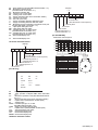
5.3.3 Details of the OSD display in the EMG display mode
During the EMG display, the OSD shows the data on the deck
mode, etc. The details of the display contents are as follows.
Notes:
• The display is variable depending on the part No. of the
System Control microcomputer (IC3001) built into the
VCR. In the following, refer to the figure carrying the
same two characters as the top two characters of the
part number of your IC.
• The sensor information in the OSD display contents is
partially different from the mechanism sensor information in EMG detail information <1>.
[For MN* only]
AA
BB
CC
DD
EE
FF
GG
HH
I I
JJ
KK
LL
MM
NN
OO
PP
QQ
RR
SS
TT
UU
VV
WW
XX
YY
AA
BB
PP
: Deck operation mode (See EMG detail information <1>.)
: Mechanism operation mode
(See EMG detail of information <1>.)
: Mechanism transition flag
: Capstan motor control status
: Loading motor control status
: Sensor information (See sensor information details.)
: Capstan motor speed
: Key code (JVC code)
: Supply reel winding diameter data higher 8 bits.
: Supply reel winding diameter data lower 8 bits.
: Mechanism sensor information & mechanism mode position(See EMG detail of information <1>.)
: Tape speed data higher 8 bits.
: Tape speed data lower 8 bits.
: Cassette tape type <2> higher 8 bits.
(See EMG detail of information <2>.)
: Cassette tape type <2> lower 8 bits.
(See EMG detail of information <2>.)
: General data display area
YY
: General data display area
CC
DD
EE
FF
GG
HH
II
JJ
KK
LL
MM
NN
OO
<Display>
** h
*
*
*
*
*
*
*
*
Encoder data
(See Mechanism mode sequence.)
Remote pause
End sensor
Start sensor
Cassette tab present = 1
Cassette tab broken = 0
[For both MN*/HD*]
Mechanism mode sequence
Mechanism mode - Encoder data
*FF:Sensor information details
1
2
3
4
5
6
7
8
9
10
11
LSA
<Display>
** h
LSB
LSC
*
*
*
*
*
*
*
LSD
Encoder output = Low
or
Trerminal - GND = SHORT
Encoder data
(See Mechanism mode sequence.)
Cassette tab present = 1
Cassette tab broken = 0
Cassette absent = 1
Cassette present = 0
Start sensor
End sensor
[For *HD only]
AA
BB
CC
DD
EE
FF
GGGG
HHHH
I I
JJJJ
KKKK
LLLL
No.
1
2
3
4
5
6
7
8
9
10
11
12
Position
EJECT
EJECT1
EJECT2
ULSTOP
UPPER
ONSTOP(PLAY)
FWD/SS
REV/SS
OFFSTOP
FFREW-BRAKE
FFREW
MIDDLE
Encoder output = High
or
Trerminal - GND = OPEN
Encoder data
0 h = 0000
1 h = 0001
2 h = 0010
3 h = 0011
4 h = 0100
5 h = 0101
6 h = 0110
7 h = 0111
8 h = 1000
9 h = 1001
A h = 1010
F h = 1111
LSD
LSC
LSB
LSA
GND
*
5 4 3 2 1
MMMM
ROM No.
AA
BB
: Key code (JVC code)
: Deck operation mode(See EMG detail information
<1>.)
CC
: Mechanism operation mode (See EMG detail information <1>.)
DD
: Sensor information (See sensor information details.)
EE
: Capstan motor speed (Search, double speed)
FF
: Tracking value
GGGG : Cassette tape type <2>, 16 bits.
(See EMG detail information <2>.)
HHHH : Supply reel winding diameter data
II
: Capstan motor speed (FF/REW, double speed)
JJJJ
: Tape speed data, lower 8 bits.
KKKK : General data display area
LLLL : General data display area
MMMM : General data display area
*DD:Sensor information details
(No.YD006)1-17
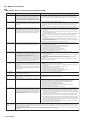
5.3.4 EMG content description
Note:
EMG contents “E09” are for the model with Dynamic Drum (DD).
FDP
CONTENT
CAUSE
E01: Loading EMG
If the mechanism mode does not change to the next mode within 4 seconds after the loading motor starts rotating in the loading direction, while
the mechanism is in the after-loading position (with the tape up against
the pole base), [E:01] is identified and the power is switched OFF.
However, if the tape loading is not completed within 4 seconds after
the loading motor starts rotating in the loading direction, the tape is
simply unloaded and ejected. No EMG data is recorded in this case.
1. The mechanism is locked in the middle of the mode transition during a tape loading operation.
2. The mechanism overruns during the tape loading operation because the SYSCON cannot recognize
the mechanism mode normally. This problem is due to a cause such as a rotary encoder failure.
3. Power is not supplied to the loading MDA. (M12V/Vcc/Vref/ICP are disconnected in the middle.)
E02: Unloading EMG
When the mechanism mode cannot be changed to another mode
even when the loading motor has rotated for more than 4 seconds in the unloading direction, [E:02] is identified and the power
is turned off.
1. The mechanism is locked in the middle of mode transition.
2. Without an eject signal being sent from the SYSCON, unloading is attempted (i.e. Ejection is attempted
while the tape is still inside the mechanism.) because the SYSCON cannot recognize the mechanism
mode normally. This is due to a cause such as a rotary encoder failure. (Mechanism position:
UPPER)
3. Power is not supplied to the loading MDA. (M12V/Vcc/Vref/ICP are disconnected in the middle.)
E03: Take Up Reel
Pulse EMG
When the falling edje of the take-up reel pulse has not been generated for more than 4 seconds in the capstan rotating mode,
[E:03] is identified, the pinch rollers are turned off and stopped,
and the power is turned off. In this case, however, the mechanism should be in position after tape loading. Note that the reel
EMG is not detected during Slow/Frame advance operations.
1. The take-up reel pulse is not generated in the FWD transport modes (PLAY/FWD SEARCH/FF,
etc.) because;
1) The idler gear is not meshed with the take-up reel gear because the mechanism mal-functions for
some reason.
2) The idler gear is meshed with the take-up reel gear, but incapable of winding due to too large
mechanical load (abnormal tension);
3) The reel is rotating normally but an FG pulse is not generated due to the take-up reel sensor failure.
2. The supply reel pulse is not generated in the REV transport modes (REV SEARCH/REW, etc.)
because;
1) The idler gear is not meshed with the supply reel gear because the mechanism mal-functions for
some reason.
2) The idler gear is meshed with the supply reel gear, but incapable of winding due to too large a
mechanical load (abnormal tension);
3) The reel rotates normally but the FG pulse is not generated due to a supply reel sensor failure.
E04: Drum FG EMG
When the drum FG pulse has not been input for more than 3 seconds in the drum rotating mode, [E:04] is identified, the pinch rollers are turned off and stopped, and the power is turned off.
1. The drum could not start or the drum rotation has stopped due to too large a load on the tape,
because;
1) The tape tension is abnormally high;
2) The tape is damaged or a foreign object (grease, etc.) adheres to the tape.
2. The drum FG pulse did not reach the System controller CPU because;
1) The signal circuit is disconnected in the middle;
2) The FG pulse generator (hall device) of the drum is faulty.
3. The drum control voltage (DRUM CTL V) is not supplied to the MDA.
4. Power (M12V) is not supplied to the drum MDA.
E05: Cassette Eject
EMG
If the cassette does not reach the eject position within about 0.7
seconds after the cassette housing has started the cassette ejection operation, [E:05] is identified, the drive direction is reversed
to load the tape, the mode is switched to STOP mode with the
pinch roller OFF, and the power is switched OFF.
During the cassette insertion process, the drive direction is reversed
and the cassette is ejected if the tape is not up against the pole
base within about 3 seconds after the start of the cassette pullingin operation. If the cassette does not reach the eject position within
about 0.7 seconds after the drive mode reversal operation, [E:05]
is identified and the power is switched OFF immediately.
1. The cassette cannot be ejected due to a failure in the drive mechanism of the housing.
2. When the housing load increases during ejection, the loading motor is stopped because of lack of
headroom in its drive torque.
Housing load increasing factors: Temperature environment (low temperature, etc.), mechanism
wear or failure.
3. The sensor/switch for detecting the end of ejection are not functioning normally.
4. The loading motor drive voltage is lower than specified or power (M12V) is not supplied to the
motor (MDA).
5. When the user attempted to eject a cassette, a foreign object (or perhaps the user's hand) was
caught in the opening of the housing.
E06: Capstan FG
EMG
When the capstan FG pulse has not been generated for more
than 1 second in the capstan rotating mode, [E:06] is identified,
the pinch rollers are turned off and stopped, and the power is
turned off.However, the capstan EMG is not detected in SLOW/
STILL modes.
Note that, if the part number of the System Control IC begins with
"MN" or "M3", the capstan EMG is not detected even during the
FF/REW operation.
1. The capstan could not start or the capstan rotation has stopped due to too large a load on the tape,
because;
1) The tape tension is abnormally high (mechanical lock);
2) The tape is damaged or a foreign object (grease, etc.) is adhered to the tape (occurrence of tape
entangling, etc.).
2. The capstan FG pulse did not reach the System controller CPU because;
1) The signal circuit is disconnected in the middle;
2) The FG pulse generator (MR device) of the capstans is faulty.
3. The capstan control voltage (CAPSTAN CTL V) is not supplied to the MDA.
4. Power (M12V, SW5V) are not supplied to the capstan MDA.
E07: SW Power
Short-Circuit
EMG
When short-circuiting of the SW power supply with GND has lasted
for 0.5 second or more, [E:07] is identified, all the motors are
stopped and the power is turned off.
1. The SW 5 V power supply circuit is shorted with GND.
2. The SW 12 V power supply circuit is shorted with GND.
E08:
DVD EMG
When communication with a system computer of VHS side is not
carried out because of the defective DVD unit, or when the DVD
unit must be reset
1. The DVD unit is defective.
2. Contact failure of the wires in the DVD unit or VHS side.
E09:
DD FG EMG
When the DD FG pulse is not generated within 2.5 seconds, [E:09]
is identified, the tilt motor is stopped and the power is turned off.
1.
2.
3.
4.
5.
6.
7.
8.
9.
When the falling edge of the supply reel pulse has not been generated for more than 10 seconds in the capstan rotating mode,
[E:0A] is identified and the cassette is ejected (but the power is
not turned off). In this case, however, the mechanism should be
in the position after tape loading (with the tape up against the pole
base). Also note that the reel EMG is not detected during Slow/
Frame advance operations.
1. The supply reel pulse is not generated in the FWD transport mode (PLAY/FWD SEARCH/FF,
etc.) because;
1) PLAY/FWD or SEARCH/FF is started while the tape in the inserted cassette is cut in the middle;
2) A mechanical factor caused tape slack inside and outside the supply reel side of the cassette shell.
In this case, the supply reel will not rotate until the tape slack is removed by the FWD transport,
so the pulse is not generated until then;
3) The reel is rotating normally but the FG pulse is not generated due to a supply reel sensor failure.
3. Power(SW5V) is not supplied to the reel sensor on the tape winding side.
E0A: Supply Reel
Pulse EMG
The FG sensor is defective. (The soldered parts have separated.)
The pull-up resistor at the FG sensor output is defective. (The soldered parts have separated.)
Contact failure or soldering failure of the pins of the connector (board-to-board) to the FG sensor.
The power (5V) to the sensor is not supplied. (Connection failure/soldering failure)
The FG pulse is not sent to the System Controller CPU.
The tilt motor is defective. (The soldered parts have separated.)
The drive power to the tilt motor is not supplied. (Connection failure/soldering failure)
The tilt motor drive MDA - IC is defective.
Auto-recovery of the DD tilting cannot take place due to overrun.
2. The take-up reel pulse is not generated in the REV transport mode (REV SEARCH/REW, etc.).
1) REV SEARCH/REW is started when the tape in the inserted cassette has been cut in the middle;
2) A mechanical factor caused tape slack inside and outside the take-up reel side of the cassette
shell. In this case, the take up will not rotate until the tape slack is removed by the REV transport,
so the pulse will not be generated until that time;
3) The reel is rotating normally but the FG pulse is not generated due to a take-up reel sensor failure.
3. The power (SW 5V) to a reel sensor is not supplied.
EU1:
Head clog warning
history
1-18 (No.YD006)
Presupposing the presence of the control pulse output in the PLAY mode, when the value obtained by mixing the two V.FM output channels (without regard
to the A.FM output) has remained below a certain threshold level for more than 10 seconds, [E:U1] is identified and recorded in the emergency history.
During the period in which the head clog is detected, the FDP shows "U:01" and the OSD repeats the "3 seconds of warning display" and the "7 seconds of
noise picture display" alternately.
EMG code : "E:C1" or "E:U1" / FDP : "U:01" / OSD : "Try cleaning tape." or "Use cleaning cassette."
The head clog warning is reset when the above-mentioned threshold has been exceeded for more than 2 seconds or the mode is changed to another mode
than PLAY.
5.3.5 EMG detail information <1>
The status (electrical operation mode) of the VCR and the status
(mechanism operation mode/sensor information) of the mechanism in the latest EMG can be confirmed based on the figure in
EMG detail information <1> .
[FDP/OSD display] *1 : *2 : 34
*1 : Deck operation mode at the moment of EMG
*2 : Mechanism operation mode at the moment of EMG
3- : Mechanism sensor information at the moment of EMG
-4 : Mechanism mode position at the moment of EMG
Note:
• For EMG detailed information <1>, the content of the
code that is shown on the display (or OSD) differs depending on the parts number of the system control microprocessor (IC3001) of the VCR. The system control
microprocessor parts number starts with two letters, refer these to the corresponding table.
*1 : Deck operation mode
[Common table of MN* and HD]
Display
MN*
HD*
00
01
02
03
04
0C
10
20
21
22
00
01
04
0E
11
22
-
24
2C
40
42
26
2E
43
-
44
4C
6C
84
85
8C
8D
8E
AC
AD
CC
CD
EC
ED
47
4C
6E
84
85
8F
AF
CD
EF
-
Deck operation mode
Mechanism being initialized
STOP with pinch roller pressure off (or tape present with P.OFF)
STOP with pinch roller pressure on
POWER OFF as a result of EMG
PLAY (Normal playback)
REC
Cassette ejected
FF
Tape fully loaded, START sensor ON, short FF
Cassette identification FWD SEARCH before transition to FF
(SPx7-speed)
FWD SEARCH (variable speed) including x2-speed
INSERT REC
REW
Cassette identification REV SEARCH before transition to REW
(SPx7-speed)
REV SEARCH (variable speed)
AUDIO DUB
INSERT REC (VIDEO + AUDIO)
FWD STILL / SLOW
REV STILL / SLOW
REC PAUSE
Back spacing
Forward spacing (FWD transport mode with BEST function)
INSERT REC PAUSE
INSERT REC back spacing
AUDIO DUB PAUSE
AUDIO DUB back spacing
INSERT REC (VIDEO + AUDIO) PAUSE
INSERT REC (VIDEO + AUDIO) back spacing
*2 : Mechanism operation mode
[Table of MN*]
Display
00
01
02
03
04
05
06
07
08
09
0A
0B
0C
0D
0E
0F
10
11
12
13
14
15
16
17
Mechanism operation mode
Command standby (No command to be executed)
Immediate Power OFF after EMG occurrence
Loading from an intermediate position during mechanism initialization
Unloading due to EMG occurrence during mechanism initialization
Ejecting cassette (ULSTOP to EJECT)
Inserting cassette (EJECT to ULSTOP)
Loading tape (ULSTOP to PLAY)
Unloading tape (PLAY to ULSTOP)
Transition from pinch roller ON to STOP
Transition from pinch roller OFF to STOP (PLAY to OFFSTOP)
Transition from pinch roller OFF to STOP at power OFF
Transition from pinch roller ON to STOP at power ON
Transition to PLAY
Transition to Search FF
Transition to REC
Transition to FWD STILL/SLOW
Transition to REV STILL/SLOW
Transition to Search REV
Transition from FF/REW to STOP
Transition to FF
Transition to REW
Tape end detection processing during loading
Short FWD/REV at tape sensor ON during unloading
Transition to FF/REW brake mode
[Table of HD*]
Display
00
01
02
04
05
0E
11
22
26
2E
43
47
4C
6E
84
85
8F
AF
C7
CD
EF
F0
F1
F2
F3
F4
F5
F6
F7
F8
F9
FA
FB
FC
FD
FE
FF
Mechanism operation mode
STOP with pinch roller pressure off
STOP with pinch roller pressure on
U/L STOP (or tape being loaded)
PLAY (Normal playback)
PLAY (x1-speed playback using JOG)
REC
Cassette ejected
FF
FWD SEARCH (variable speed) including x2-speed
INSERT REC
REW
REV SEARCH
AUDIO DUB
INSERT REC (VIDEO + AUDIO)
FWD STILL/SLOW
REV STILL/SLOW
REC PAUSE
INSERT REC PAUSE
REV SEARCH (x1-speed reverse playback using JOG)
AUDIO DUB PAUSE
INSERT REC (VIDEO + AUDIO) PAUSE
Mechanism being initialized
POWER OFF as a result of EMG
Cassette being inserted
Cassette being ejected
Transition from STOP with pinch roller pressure on to STOP with pinch
roller pressure off
Transition from STOP with pinch roller pressure on to PLAY
Transition from STOP with pinch roller pressure on to REC
Cassette type detection SEARCH before FF/REW is being executed
Tape being unloaded
Transition from STOP with pinch roller pressure off to STOP with pinch
roller pressure on
Transition from STOP with pinch roller pressure off to FF/REW
Transition from STOP with pinch roller pressure off to REC.P (T.REC,etc.)
Transition from STOP with pinch roller pressure off to cassette type
detection SEARCH
Short REV being executed after END sensor on during unloading
Tension loosening being executed after tape loading (STOP with pinch
roller pressure on)
Tape being unloaded
(No.YD006)1-19
3- : Mechanism sensor information
*5 : Cassette tape type <1>
[Common table of MN* and HD*]
Display
0123456789ABCDEF-
Display
Mechanism sensor informatio n
REC safety SW
Tab broken
Tab broken
Tab broken
Tab broken
Tab present
Tab present
Tab present
Tab present
Tab broken
Tab broken
Tab broken
Tab broken
Tab present
Tab present
Tab present
Tab present
Tab broken = 0
Tab present = 1
Start sensor
End sensor
ON
ON
ON
ON
OFF
OFF
OFF
OFF
ON
ON
ON
ON
OFF
OFF
OFF
OFF
Mechansim
position sensor
ON
ON
OFF
OFF
ON
ON
OFF
OFF
ON
ON
OFF
OFF
ON
ON
OFF
OFF
Sensor ON = 0
sensor OFF = 1
ON
OFF
ON
OFF
ON
OFF
ON
OFF
ON
OFF
ON
OFF
ON
OFF
ON
OFF
Sensor ON = 0
Sensor OFF = 1
-4 : Mechanism mode position
[Common table of MN* and HD*]
Mechanism
sensor
information
Even number
(0, 2, 4, 6, 8,
A, C, E)
Odd number
(1, 3, 5, 7, 9,
B, D, F)
Display
-0
-1
-2
-3
-4
-5
-6
-7
-8
-9
-A
-B
-C
-D
-E
-F
-0
-1
-2
-3
-4
-5
Deck operation mode
Not established
EJECT
EJECT position
EJECT-EJECT1
Intermodal position
EJECT1
EJECT1 position
EJECT1-EJECT2 Intermodal position
EJECT2
EJECT2 position
EJECT2-ULSTOP Intermodal position
ULSTOP
ULSTOP position
ULSTOP-UPPER Intermodal position
UPPER
Loading (unloading) tape
UPPER-ONSTOP Intermodal position
ONSTOP
PLAY position
PLAY-FWD/SS
Intermodal position
FWD/SS
FWD (FWD Still/Slow) position
FWD/SS-REV
Intermodal position
REV
REV (REV Still/Slow) position
REV-OFFSTOP
Intermodal position
OFFSTOP
Pinch roller OFF position
OFFSTOP-FFREWB Intermodal position
FFREWB
FF/REW Brake position
FFREWB-FFREW Intermodal position
FFREW
FF/REW position
5.3.6 EMG detail information <2>
The type of the cassette tape and the cassette tape winding position can be confirmed based on the figure in EMG detail information <2> .
Note:
• EMG detail information <2> is the reference information
stored using the remaining tape detection function of
the cassette tape. As a result, it may not identify cassette correctly when a special cassette tape is used or
when the tape has variable thickness.
1-20 (No.YD006)
00
16
82
84
92
93
C3
D3
E1
E2
E9
F1
Cassette tape type <1>
Cassette type not identified
Large reel/small reel (T-0 to T-15/T-130 to T-210) not classified
Small reel, thick tape (T-120) identified/thin tape (T-140) identified
Large reel (T-0 to T-60) identified
Small reel, thick tape (T-130) identified/thin tape (T-160 to T-210) identified
Small reel, thick tape/C cassette (T-0 to T-100/C cassette) not classified
Small reel, thick tape/C cassette (T-0 to T-100/C cassette) being classified
Small reel, thick tape/C cassette (T-0 to T-100/C cassette) being classified
C cassette, thick tape (TC-10 to TC-20) identified
Small reel, thick tape (T-0 to T-100) identified
C cassette, thin tape (TC-30 to TC-40) identified
C cassette, thick tape/thin tape (TC-10 to TC-40) not classified
Notes:
• Cassette tape type <1> is identified a few times during
mode transition and the identification count is variable
depending on the cassette tape type. If an EMG occurs
in the middle of identification, the cassette tape type
may not be able to be identified.
• If other value than those listed in the above table is displayed, the cassette tape type is not identified.
*6 : Cassette tape winding position
The cassette tape winding position at the moment of EMG is displayed by dividing the entire tape (from the beginning to the end)
in 21 sections using a hex number from “00” to “14”.
00 : End of winding
14 : Beginning of winding
FF : Tape position not identified
*7 : Cassette tape type <2> (Winding area)
Display
Cassette tape type <2>
(Reference) Word data
(Beginning)
(End)
00
04 - 08
05 - 06
05 - 0C
06 - 0C
06 - 0C
07 - 08
09 - 0B
0C - 0D
0D - 0F
0E - 10
10 - 12
10 - 13
11 - 14
12 - 14
13 - 14
13 - 14
13 - 14
13 - 14
15 - 16
16 - 17
17 - 18
19 - 1B
Cassette type not identified
C cassette, thick tape
TC-10
Small reel, thick tape
T-20
C cassette, thick tape
TC-20P
C cassette, thin tape
TC-40
C cassette, thin tape
TC-30
Small reel, thick tape
T-40
Small reel, thick tape
T-60
Small reel, thick tape
T-80(DF-160)
Small reel, thick tape
T-90(DF-180)
Small reel, thick tape
T-100
Small reel, thin tape
T-140
Small reel, thick tape
T-120(DF-240)
Small reel, thick tape
T-130
Small reel, thin tape
T-160
Small reel, thin tape
T-210(DF-420)
Small reel, thin tape
T-180(DF-360)
Small reel, thin tape
T-168
Small reel, thick tape
DF-300
Large reel
T-20
Large reel
T-30
Large reel
T-40
Large reel
T-60
(0497 - 0506) (0732 - 0858)
(05A9 - 0661)
(0599 - 05FF) (0AA1 - 0C07)
(0623 - 063D) (0C41 - 0CC3)
(0611 - 0638) (0C0C - 0CB2)
(07CC - 08E5)
(09FD - 0B78)
(0C20 - 0DFC)
(0D31 - 0F3E)
(0E43 - 107F)
(10E1 - 120C)
(1073 - 1313)
(1185 - 1429)
(12D3 - 141F)
(1373 - 14C3)
(1357 - 14C0)
(1395 - 14EE)
(13A8 - 14CE)
(1536 - 1618)
(1647 - 175A)
(1759 - 189C)
(1989 - 1B2F)
Note:
• The values of cassette tape type <2> in the above table
are typical values with representative cassette tapes.
5.3.7 EMG detail information <3>
Three deck operation modes preceding the deck operation mode
in which the EMG occurs may be confirmed based on the figures
in the EMG information detail <3>. For the contents of the displayed information, see the table "Deck operation mode" in section "5.3.5 EMG detail information <1>".
5.4
Display function of DVD section
5.4.1 Displaying SYSTEM INFO
SYSTEM INFO contains information on firmware version of the unit and the mechanism drive, and an initialize execution menu.
(1) Set the unit to the Jig RCU mode.
(2) Transmit "8b" from the JIG RCU.
(3) SYSTEM INFORMATION menu is displayed in the screen.
(4) To move cursor in SYSTEM INFO, use the " ", " ", " ", and " " buttons of a remote control unit attached to product.
(5) To quit the SYSTEM INFO menu, transmit "8b" from the JIG RCU..
(6) Cancel JIG RCU mode.
SYSTEM INFO
VERSION
INITIALIZE
CPRM Key Downl oad
INFORMATION
Done
PROD101 / JVC03_44-2
C-Ware / A-Ware
JVRI / Host
0081-2 / V0128-2J
1394 / OSD
0053 / MTEN03
Anal og / BE-R / FE-R
SET UP
ENTER
SELECT
004 / 2 / 2
SELECT WITH [CURSORS]
THEN PRESS [ENTER]
Version of firmware
this part is updated sfter the firmware
of the unit is upgraded.
System controller version/
Region code (back end)/
Region code (front end)
SYSTEM I NFO
VERSION
INITIALIZE
Si l i co n ve rsi o n o f E5
1B0
1.2/010
BSP
Dri ve f i rm wa re ve rsi o n
Dri ve l a st e rro r
SET UP
INFORMATION
ENTER
SELECT
P201
Drive firmware version
00 00 00
SELECT WITH [CURSORS]
THEN PRESS [ENTER]
NOTE:
Items other than the ones described above are not used in service work.
5.4.2 Upgrading firmware of the unit
• Firmware upgrade disk supports only DVD-RAM media
• When firmware needs to be upgraded, Digital Video Storage CSG will distribute a firmware upgrade disk.
(1) Set the unit to the Jig RCU mode.
(2) Set the unit to DVD mode.(DVD lamp lights up)
(3) Transmit "70" from the JIG RCU.
(4) "UPDATE" appears in FDP, load the upgrade disk on the disk tray then close the disk tray.
(5) Wait for approx.30 seconds while FDP is displayed as "UPDATE."
(6) Then, "FW UPDATE" appears in FDP. It takes approx. 3 minutes at maximum to upgrade firmware.
(7) The tray is ejected. Then, take out the disk and close the tray.
(8) The tray is ejected. Then, take out the disk and close the tray.Turn off the unit, and unplug the AC power cord from the AC outlet.
Then plug the AC power cord into the AC outlet.
(9) "LOADING" of FDP disappears. then, turn on the unit.
(10) Display the SYSTEM INFO menu, and check the version of the firmware.
(11) Cancel the JIG RCU mode
ATTENTION :
Firmware may sometimes not be upgraded successfully.
If firmware is not upgraded successfully, the tray opens, and "ERROR" appears in FDP.
If firmware is upgraded successfully, the tray opens, and "OPEN" appears in FDP.
If unplug the AC power cord from the AC outlet while "ERROR" appears, data in the flash memory is destroyed and the unit cannot
start: the flash memory needs to be replaced.
After upgrading procedure, pay enough attention to FDP when the tray opens.
When "ERROR" appears, upgrade firmware again in the following way to restore the firmware
(1) Transmit "70" from theJIG RCU while the tray opens.
(2) When "UPDATE" appears in FDP, close the tray and make the unit read the disk. Upgrading starts.
(3) After (2), perform upgrading procedure (4) - (10) of 5.4.2 Upgrading firmware of the unit above.
(No.YD006)1-21
5.4.3 The exchange method of a tray fitting
When DVD unit is exchanged, please transplant a tray fitting from an old drive, or change for a new tray fitting.
5.4.4 Initialization method
Since the information on internal is as follows if it initializes, before enforcement, it is required to surely obtain the approval of a customer.
All initial setting of DVD returns to an initial state.
(1) Set the unit to theJIG RCU mode.
(2) Set the unit to DVD mode.(DVD lamp lights up)
(3) Press the "POWER" button on the unit to turn off the unit.
(4) Transmit "6F" from the JIG RCU.
(5) Confirm the FDP changes from "FACTORY" to "CHECK OK".
(6) Press the "VCR/DVD" buttojn on the unit so that the VCR lamp lights up on the unit.
(7) To cancel JIG RCU mode transmit "9D" from the JIG RCU.
5.4.5 The setting method of a region code
A region code should be set after a DVD unit is replaced.
While a DVD unit is in a warehouse as a stock, a region code of the DVD unit is not determined.
Only replacement of a DVD unit may cause abnormal playback of Disc.
Set a region code of a DVD unit in the following procedure.
(1) Replace a DVD unit.
(2) Set the unit to JIG RCU mode.
(3) nsert a DVD-RAM disc in the unit to make the unit read the DVD-RAM disc.(The DVD-RAM disk used in this procedure is not a
disk for upgrade. If it is a DVD-RAM disk, it is good anything.)
(4) Transmit "F2" from the JIG RCU.
(5) "REGION 1" is displayed on FDP.
(6) Set the unit to STANDBY mode.
(7) Turn the POWER switch ON.
(8) To cancel JIG RCU mode transmit "9D" from the JIG RCU.
(9) Colon is displayed on a clock on FL display.
(10) Setting is completed in the procedure above.
1-22 (No.YD006)
(No.YD006)1-23
JVC SERVICE & ENGINEERING COMPANY OF AMERICA
DIVISION OF JVC AMERICAS CORP.
www.jvcservice.com(US Only)
JVC CANADA INC.
Head office : 21 Finchdene Square Scarborough, Ontario M1X 1A7
(No.YD006)
(416)293-1311
Printed in Japan
WPC