1
EPSON TERM NAL PR NTER
LX-300
SERVICE MANUAL
(
)
EPSON
PRECAUTIONS
Precautionary notations throughout the text are categorized relative to 1) personal injury and 2)
damage to equipment.
DANGER Signals a precaution which, if ignored, could result in serious or fatal personal injury.
Great caution should be exercised in performing procedures preceded by DANGER
Headings.
WARNING Signals a precaution which, if ignored, could result in damage to equipment.
The precautiomry measures itemized below should always be observed when performin grepair/
maintenance procedures.
DANGER
1.
ALWAYS DISCONNECT THE PRODUCT FROM BOTH THE POWER SOURCE AND
PERIPHERAL DEVICES PERFORMING ANY MAINTENANCE OR REPAIR PROCEDURE.
2. NO WORK SHOULD BE PERFORMED ON THE UNIT BY PERSONS UNFAMILIAR WITH
BASIC SAFETY MEASURES AS DICTATED FOR ALL ELECTRONICS TECHNICIANS IN
THEIR LINE OF WORK.
3. WHEN PERFORMING TESTING AS DICTATED WITHIN THIS MANUAL, DO NOT
CONNECT THE UNIT TO A POWER SOURCE UNTIL INSTRUCTED TO DO SO. WHEN
THE POWER SUPPLY CABLE MUST BE CONNECTED, USE EXTREME CAUTION IN
WORKING ON POWER SUPPLY AND OTHER ELECTRONIC COMPONENTS.
1.
REPAIRS ON EPSON PRODUCT SHOULD BE PERFORMED ONLY BY AN EPSON
CERTIFIED REPAIR TECHNICIAN.
2. MAKE CERTAIN THAT THE SOURCE VOLTAGE IS THE SAME AS THE RATED VOLT-
AGE, LISTED ON THE SERIAL NUMBER/RATING PLATE. IF THE EPSON PRODUCT
HAS A PRIMARY AC RATING DIFFERENT FROM AVAILABLE POWER SOURCE, DO
NOT CONNECT IT TO THE POWER SOURCE.
3. ALWAYS VERIFY THAT THE EPSON PRODUCT HAS BEEN DISCONNECTED FROM
THE POWER SOURCE BEFORE REMOVING OR REPLACING PRINTED CIRCUIT
BOARDS AND/OR INDIVIDUAL CHIPS.
4.
IN ORDER TO PROTECT SENSITIVE MICROPROCESSORS AND CIRCUITRY, USE
STATIC DISCHARGE EQUIPMENT, SUCH AS ANTI-STATIC WRIST STRAPS, WHEN
ACCESSING INTERNAL COMPONENTS.
5. REPLACE MALFUNCTIONING COMPONENTS ONLY WITH THOSE COMPONENTS
BY THE MANUFACTURE; INTRODUCTION OF SECOND-SOURCE ICS OR (YI’HER
NONAPPROVED COMPONENTS MAY DAMAGE THE PRODUCT AND VOID ANY
APPLICABLE EPSON WARRANTY.
- ii -
PREFACE
This manual describes functions, theory of electrical and mechanical operations, maintenance, and repair
of LX-300.
The instructions and procedures included herein are intended for the experience repair technician, and
attention should be given to the precautions on the preceding page. The chapters are organizd as
follows:
CHAPTER 1. PRODUCT DESCRIPTION
Provides a general product overview, lists specifications, and illustrates the main components of the pMter.
CHAPTER 2. OPERATING PRINCIPLES
Describes the theory of printer operation.
CHAPTER 3. DISASSEMBLY AND ASSEMBLY
Includes a step-by-step guide for product d isassembly and assembly.
CHAPTER 4. ADJUSTMENTS
Includes a step-by-step guide for adjustment.
CHAPTER 5. TROUBLESHOOTING
Provides Epson-approved techniques for adjustment.
CHAPTER 6. MAINTENANCE
Describes preventive maintenance techniques and lists lubricants and adhesives required to service the equipment.
APPENDIX
Describes connector pin assignments, circuit diagrams, circuit board component layout and exploded diagram.
The contents of this manual are subject to change without notice.
-iv-
.......
(
REVISION SHEET
Revision
Issue Date
Revision Page
Rev. A
April 6, 1994
1st issue
4
-v-
( j
TABLE OF CONTENTS
CHAPTER 1.
CHAPTER 2.
CHAPTER 3.
CHAPTER 4.
CHAPTER 5.
CHAPTER 6.
APPENDIX
PRODUCT DESCRIPTION
OPERATING PRINCIPLES
DISASSEMBLY AND ASSEMBLY
ADJUSTMENTS
TROUBLESHOOTING
MAINTENANCE
- vi -
CHAPTER 1 Product Description
Table of Contents
1.1 FEATURES
1-1
1-2
1.2 SPECIFICATIONS
1.2.1 Hardware Specifications . . . . . . . . . . . . . . . . . . . . . . . . . . . . . . . . . . . . . 1-2
1.2.1.1 Paper Handling Specifications . . . . . . . . . . . . . . . . . . . . . . . . . . 1-3
1.2.1.2 Paper Specifications. . . . . . . . . . . . . . . . . . . . . . . . . . . . . . . . . . 1-4
1.2.1.3 Printable Area.. . . . . . . . . . . . . . . . . . . . . . . . . . . . . . . . . . . . . . 1-5
1.2.1.4 Ribbon Specifications. . . . . . . . . . . . . . . . . . . . . . . . . . . . . . . . . 1-7
1.2.1.5 Electrical Specifications . . . . . . . . . . . . . . . . . . . . . . . . . . . . . . . 1-8
1.2.1.6 Environmental Conditions. . . . . . . . . . . . . . . . . . . . . . . . . . . . . . 1-8
1.2.1.7 Reliability. . . . . . . . . . . . . . . . . . . . . . . . . . . . . . . . . . . . . . . . . . . 1-8
1.2.1.8 SafetyApprovals. . . . . . . . . . . . . . . . . . . . . . . . . . . . . . . . . . . . . 1-8
1.2.1.9 Physical Specifications . . . . . . . ...’..... . . . . . . . . . . . . . . . . . 1-8
1.2.2 Firmware Specifications. . . . . . . . . . . . . . . . . . . . . . . . . . . . . . . . . . . . . . 1-9
1-11
1.3 INTERFACE SPECIFICATIONS
1.3.1 Parallel Interface Specifications. . . . . . . . . . . . . . . . . . . . . . . . . . . . . . . 1-11
1.3.2 Serial InterfaceSpecifications . . . . . . . . . . . . . . . . . . . . . . . . . . . . . . . . 1-13
1-14
1.4 OPERATING INSTRUCTIONS
1.4.1 Control Panel Operation . . . . . . . . . . . . . . . . . . . . . . . . . . . . . . . . . . . . 1-14
1.4.2 Self-test Function. . . . . . . . . . . . . . . . . . . . . . . . . . . . . . . . . . . . . . . . . . 1-15
1.4.3 Hexadecimal Dump Function. . . . . . . . . . . . . . . . . . . . . . . . . . . . . . . . . 1-15
1.4.4 PrinterStatus Indication. . . . . . . . . . . . . . . . . . . . . . . . . . . . . . . . . . . . . 1-15
1.4.5 Selected Font . . . . . . . . . . . . . . . . . . . . . . . . . . . . . . . . . . . . . . . . . . . . 1-15
1.4.6 Paper Position Adjustments. . . . . . . . . . . . . . . . . . . . . . . . . . . . . . . . . . 1-15
1.4.7 Printer Initialization . . . . . . . . . . . . . . . . . . . . . . . . . . . . . . . . . . . . . . . . 1-16
1.4.7.1 Hardware Initialization. . . . . . . . . . . . . . . . . . . . . . . . . . . . . . . . 1-16
1.4.7.2 Software Initialization . . . . . . . . . . . . . . . . . . . . . . . . . . . . . . . . 1-16
1.4.8 PrinterSettings . . . . . . . . . . . . . . . . . . . . . . . . . . . . . . . . . . . . . . . . . . . 1-16
1.4.8.1 Selectable PrinterSettings . . . . . . . . . . . . . . . . . . . . . . . . . . . . 1-16
1.4.8.2 Changing the DefaultSettings. . . . . . . . . . . . . . . . . . . . . . . . . . 1-17
1-21
1.5 MAIN COMPONENTS
1.5.1 Ct30 MAIN Board. , . . . . . . . . . . . . . . . . . . . . . . . . . . . . . . . . . . . . . . . 1-21
1.5,2 C130 PSB/PSE Board. . . . . . . . . . . . . . . . . . . . . . . . . . . . . . . . . . . . . . 1-21
List of Figures
Figure
Figure
Figure
Figure
Figure
Figure
Figure
Figure
Figure
Figure
.P.::k
f
(’.
1-1. Exterior View of the LX-300. . . . . . . . . . . . . . . . . . . . . . . . . . . . . . . 1-1
1-2. Pin Configuration. . . . . . . . . . . . . . . . . . . . . . . . . . . . . . . . . . . . . . . 1-2
1-3. PrintableArea forCut Sheets Using Manual Insertion. . . . . . . . . . . 1-5
1-4. Printable Area for Cut Sheets with the CSF. . . . . . . . . . . . . . . . . . . 1=6
1-5. PrintableArea forContinuous Paper . . . . . . . . . . . . . . . . . . . . . . . . 1-6
1-6. PrintableArea forRoll Paper . . . . . . . . . . . . . . . . . . . . . . . . . . . . . . 1-7
1-7. Data Transmission Timing . . . . . . . . . . . . . . . . . . . . . . . . . . . . . . . 1-11
1-8. Panel Appearance . . . . . . . . . . . . . . . . . . . . . . . . . . . . . . . . . . . . . 1-14
1-9. C130 MAIN Board Component Layout. . . . . . . . . . . . . . . . . . . . . . 1-21
1-10. C130 PSB/PSE Board Component Layout . . . . . . . . . . . . . . . . . 1-21
List of Tables
Table l-1. Optional Units . . . . . . . . . . . . . . . . . . . . . . . . . . . . . . . . . . . . . . . . . . 1-1
Table 1-2. Feeding Speed . . . . . . . . . . . . . . . . . . . . . . . . . . . . . . . . . . . . . . . . . 1-3
Table l-3. Adjust LeverSettings . . . . . . . . . . . . . . . . . . . . . . . . . . . . . . . . . . . . 1-3
Table 1-4. Specifications for Cut Sheet Paper (Manual Insertion) . . . . . . . . . . . 1-4
Table 1-5. Specifications for Cut Sheet Paper (CSF). . . . . . . . . . . . . . . . . . . . . 1-4
Table l-6. Envelope Specifications . . . . . . . . . . . . . . . . . . . . . . . . . . . . . . . . . . 1-4
Table 1-7. Specifications for Continuous Paper (Single Sheet and Multi-Part) . 1-4
Table 1-8. Specifications for Continuous Paper with a Label. . . . . . . . . . . . . . . 1-5
Table l-9. Roil Paper Specifications . . . . . . . . . . . . . . . . . . . . . . . . . . . . . . . . . 1-5
Table l-10. Electrical Specifications. . . . . . . . . . . . . . . . . . . . . . . . . . . . . . . . . . 1-8
Table 1-11, Environmental Conditions. . . . . . . . . . . . . . . . . . . . . . . . . . . . . . . . 1-8
Table 1-12. Character Tables. . . . . . . . . . . . . . . . . . . . . . . . . . . . . . . . . . . . . . . 1-9
Table 1-13. Printing Speed.. . . . . . . . . . . . . . . . . . . . . . . . . . . . . . . . . . . . . . . 1-10
Table 1-14, Resolution . . . . . . . . . . . . . . . . . . . . . . . . . . . . . . . . . . . . . . . . . . . 1-10
Table 1-15 Signal and Connector Pin Assignments for the Parallel Interface. 1-12
(T
Table 1-16. Signal and Connector Pin Assignments for the Serial Interface . . 1-13
Table 1-17 Font Selection. . . . . . . . . . . . . . . . . . . . . . . . . . . . . . . . . . . . . . . . 1-15 ‘:”””
Table 1-18 Font Lights and Language Selection. . . . . . . . . . . . . . . . . . . . . . . 1-17
Table 1-19 Default Options. . . . . . . . . . . . . . . . . . . . . . . . . . . . . . . . . . . . . . . 1-17
Table 1-20 Character Spacing. . . . . . . . . . . . . . . . . . . . . . . . . . . . . . . . . . . . . 1-18
Table 1-21 Shape of Zero. . . . . . . . . . . . . . . . . . . . . . . . . . . . . . . . . . . . . . . . 1-18
Table -22 Skip Over Perforation . . . . . . . . . . . . . . . . . . . . . . . . . . . . . . . . . . 1-18
Table -23 Character Table . . . . . . . . . . . . . . . . . . . . . . . . . . . . . . . . . . . . . . 1-18
Table -24 Auto Line Feed . . . . . . . . . . . . . . . . . . . . . . . . . . . . . . . . . . . . . . . 1-19
Table -25 Page Length . . . . . . . . . . . . . . . . . . . . . . . . . . . . . . . . . . . . . . . . . 1-19
Table -26 Auto Tear Off. . . . . . . . . . . . . . . . . . . . . . . . . . . . . . . . . . . . . . . . . 1-19
Table -27 Tractor. . . . . . . . . . . . . . . . . . . . . . . . . . . . . . . . . . . . . . . . . . . . . . 1-19
Table 1-28. Interface . . . . . . . . . . . . . . . . . . . . . . . . . . . . . . . . . . . . . . . . . . . . 1-19
Table 1-29. Bit Rate. . . . . . . . . . . . . . . . . . . . . . . . . . . . . . . . . . . . . . . . . . . . . 1-19
Table 1-30. Parity Bit . . . . . . . . . . . . . . . . . . . . . . . . . . . . . . . . . . . . . . . . . . . . 1-20
Table 1-31. Data Length. . . . . . . . . . . . . . . . . . . . . . . . . . . . . . . . . . . . . . . . . . 1-20
Table 1-32. EWACK. . . . . . . . . . . . . . . . . . . . . . . . . . . . . . . . . . . . . . . . . . . . . l-2o
Product Daadption
LX-300 Service Manual
1.1
FEATURES
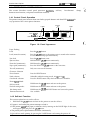
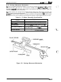
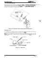
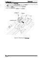
The LX-300 is a small, light-weight, 9-pin serial impact dot-matrix color printer suitable for
personal use. The major features of this printer areas follows:
0 Fast printing of 10-cpi draft characters at 220 cps
Cl Compact design saves precious workspace
Cl Easy-to-operate panel
LI Quiet printing
CI Standard 8-bit parallel interface and EIA-232D serial interface
D Printing of up to 66 lines on A4-size or 62 lines on letter-size paper
~ Optional color printing usinga color ribbon (black, magenta, cyan, yellow)
~ Detachable push and pull tractor
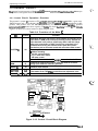
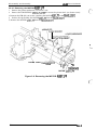
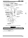
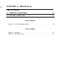
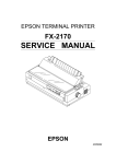
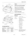
Figure 1-1 shows an exterior view of the LX-300 and Table 1-1 lists the optional units available for
the LX-300.
~p”perwppof’s
A
Edge guties ~
lease
r
YA&
feed
b
Power
..
w./,
5
/’=
A%
Pfintercover
#/<
Print head
A
Sprocket unit
Paper Jpport
Troctof
-
Figure 1-1. Exterior”View of the LX-300
Table 1-1. Optional Units
I
Description
Model
#8750
Ribbon cartridge (monochrome)
#8758
I
Rev. A
Ribbon cartridge (monochrome, sub-mtridge)
,
I Ribbon cartridge (color)
S015073
C80837*
Single-bin cut sheet feeder
C83208*
Color upgrade kit
I
C80030*
I
#8310
I
[
I
Pulitractorunit
I
I Roil paper holder
I
1-1
a
LX-300 Sarvice Mimual
Product Description
1.2 SPECIFICATIONS
/- . :.,,
: ,.f
This section provides detailed information about the LX-300.
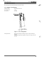
1.2.1 Hardware Specifications
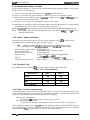
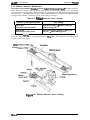
Printing method:
Serial impact dot matrix
Pin configuration:
9 wires
Pin diameter:
0.29 mm
Figure 1-2. Pin Configuration
Printing direction:
1-2
Bidirectional with logic seeking for draft text with monochrome
printing.
Unidirectional printing for graphics, NLQ text, bit image, and color
printing.
Rev. A
Product Description
LX-XXI Sarvka Manual
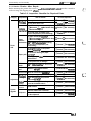
1.2.1.1 Paper Handling Specifications
Friction feed or tractor (push and pull) feed
Feeding system:
Feeding method
Cut sheets:
Manual insertion (top entry) and feeding with the
optional cut sheet feeder (CSF)
Push and pull tractor feeding
li~ in~, 1A in~, or pr~ammable feeding in in~ments
of %16 inch, minimum
Continuous paper:
Feeding pitch:
Paper paths
Cut sheet path:
Continuous paper paths:
Continuous paper parking:
CSF:
Paper-feeding speed:
Top entry (manual insertion or the optioml CSF)
Rear entry (push tractor feed)
Rear entry (pull tractor feed)
Possible, using push tractor
Single bin, manual insertion using optional CSF (top entry)
See Table 1-2.
Table 1-2. Feeding Speed
Feeding
Friction
Tractor (single)
Tractor (double)
l/G inoh Line Feed
Continuous Feed
79 rns/line
2.78 incheskecond
96 redline
2.08 inoheakxond
Friction feed
● Set the release lever to the friction msition.
. When a sheet is inserted into the t;p slot, place its left edge at the marked position.
. Donotperform reverse feeds greater than O.27inch(6.8 mm).
Push tractor feed
. Set the release lever to the tractor position.
. Donotperform reverse feeds greater than O.27 inch (6.8 mm).
. During printing ofiabels, never perforrnreverse feeding.
. After printing labels, do not eject them from the rear.
Pull tractor feed
0 Remove the tractor unit from the push position and mount it in the pull position.
● Do not perform reverse feeding.
The adjust lever must be set to proper position for the paper thickness, as shown below.
Table 1-3. Adjust Lever Settings
Lever Position
b
Rev. A
Paper Thickness
o
0.065 mm -0.16 mm (0.0026 in. -0.0063 in.)
1
0.16 mm -0.25 mm (0.0063 in. -0.0098 in.)
2
0.25 mm -0.48 mm (0.0098 in. -0.0189 in.)
14
LX-WI Service Manual
Product Description
1.2.1.2 Paper Specifications
,..
(i
Table 1-4. Specifications for Cut Sheet Papar (Manual Insertion)
Width
182 mm -257 mm (7.2 in. -10.1 in.)
Length
182 mm -364 mm (7.2 in. -14.3 in.)
Thickness
0.065 mm -0.14 mm (0.0025 in. -0.0055 in.)
Weight
52.3-90 g/m2 (14 -24 lb.)
Quality
Plain paper, recycled paper
‘-’;
Table 1-5. Specifications for Cut Sheet Paper (CSF)
Size
A4 (W x L: 210 mm (8.3 in.) x 297 mm (11.7 in.))
Letter (’W x L: 216 mm (8.5 in.) x 279 mm (11.0 m.))
Thickness
0.065 mm -0.14 mm (0.0025 in. -0.0055 in.)
Weight
64-90 @m* (17 -24 lb.)
QuaMy
Plain paper, recycled paper
Table 1-6. Envelope Specifications
Size
Width 166 mm x Length 92 mm (6.5 in. x 3.6 in.)
NO.6
No.1O Width 240 mm x Length 104 mm (9.5 in. x 4.1 in.)
Thickness
0.16 mm - 0.48 mm (0.0063 in. -0.019 in.)
Weight
45-90 g/m2 (12 1-24 lb.)
Quality
Bond paper (not curled, folded, or crumpled), plain paper, airmail paper
Notes:
. Printing of envelopes is guaranteed only when the temperature is room temperature
and humidity is normal (15 - 25° C (59 - 77” F), 20- &l’Y. RI-I).
● Variations in envelope thickness must be less than 0.25 mm (0.0098 in.).
● When inserting envelopes, keep the longer side horizontal.
Table 1-7. Specifications for Continuous Paper (Single Sheet and Multi-Part)
Width
I Total thickness
101.6 mm - 254 mm (4.0 in. - 10.0 in.)
I
I 0.065 mm- 0.25 mm (0.0025 in. - 0.0098in.)
copies
52.3- 82 g/m2 14-22 lb. — not multi-part
40- 58.2 g/m2 12
) multi-part
[ - 15 lb. —
3 sheets (1 original + 2 copies)
Quality
Plain paper, recycled paper, carbonless multi-part paper
Weights
14
I
Rev. A
(“:.
Prvduct Description
LX-300 Service Manual
Table 1-8. Specifications for Continuous Paper with a Label
Label size (W x L)
63.5 mm (min.) x 23.8 mm (min.) [ 2.5 in. (min.) x 15/16 in. (min.)]
Width of base paper
101.6 mm -254 mm (4.0 in. x 10.0 in.)
Thickness of base
paper
0.07 mm - 0.09 mm (0.0028 in. - 0.0035 in.)
Total thickness
0.16 mm - 0.19 mm (0.0063 in. -0.0075 in.)
Weight
64g/m2(17 lb.)
Quality
Plain paper
Notes:
I
Use only continuous-type labels and use them only with the tractor.
— Avery Continuous Form Labels
● Example of labels
— Avery Mini-Line Labels
● Printing of envelopes is guaranteed only when the temperature is room temperature
and humidity is normal (15 - 25° C (59 - 77° F), 20- 6(YXO RI-l).
●
Table 1-9. Roll Paper Specifications
Width
213 mm -219 mm (8.38 in. -8.62 in.)
Diameter
127 mm (5.0 in.)
Thickness
0.070 mm -0.090 mm (0.0028 in. - 0.0035 in.)
Weiaht
I
I 52- 64a/m2 (14 -17 lb.)
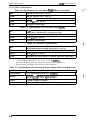
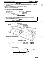
1.2.1.3 Printable Area
Cut shaets using manual insartion
3 mm
[0 1%], nym.m
3 mm
[0.12’]. Ilirimbm
. . . . . . . . . . . . ,.. - . . ,
\
Printable Area
209.2 mm 10~. MEximum
—
—
—
F
XYz
BC
L
)wz
-J
BC
7
Figure 1-3. Printable Area for Cut Sheets Using
Manual Insertion
Rev. A
1-s
LK300 Service Manual
Product Description
Cut Sheets Using the (XF
3 mm
10.12”1. mm,mum
A
L
XY
BC
Figure 1-4. Printable Area for Cut Sheets Using the CSF
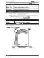
Continuous paper
101.6 t-m-n - 2S4 nun [4” - 10~, masinwm
0
0
o
I
1:0
0
0
0
0
0
0
0
0
0
0
0
0
0
0
0
0
0
0
0
0
0
0
0
0
0
0
0
0
0
0
0
42
0
0
0
0
0
0
0
o
0
0
0
0
0
0
0
0
0
0
0
0
a
o
0
0
0
1
PfintaM9 Area
f“’.
- .;.
0
0
0
0
0
0
0
0
0
a
o
0
0
0
a
o
a
a
a
a
a
a
—a
“ 13 mm (0.51”) or more whm ppar wid?h of 101.6 MM (4-) to 241.3 mm (9.5-) is usd
30 mm (1. W) w mwe when w w+dth of 2S4 mm (10.) is usad.
Figure 1-5. Printable Area for Continuous Paper
14
Rev. A
Prvduct Description
LX4tW Service Manual
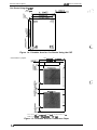
Roll paper
213 mm -219 mm [8.38’ - 8.62’]
3 mm [0.12”
minimum
w
I
>
*
203.2 mm [8’J maximum
Printable Area
)
I
m
‘ 9.8 mm (0.39”) or more
when a paper widthof216 f 3 mm is used.
Figure 1-6. Printable Area for Roll Paper
1.2.1.4 Ribbon Specifications
Ribbon cartridge (mono):
#8750
#8758 (sub-cartridge)
Ribbon cartridge (color):
S015073
Ribbon color:
Black, magenta, cyan, yellow
Black ribbon life:
Color ribbon life
Black:
Magenta:
Cyan:
Yellow:
3 million characters (14 dots/character)
Rev. A
1 million characters (14 dots/character)
0.7 million characters (14 dots/character)
0.7 million characters (14 dots/character)
0.5 million characters (14 dots/character)
1-7
LX-300 Service Manual
Product Description
1.2.1.5 Electrical Specifications
Table 1-10. Electrical Specifications
120 V Version
220-240 V Version
120 VAC
220-240 VAC
103.5-132 VAC
198-264 VAC
Description
Rated voltage
Input voltage range
r
Rated frequency range
50-60 Hz
Input frequency range
49.5 -60.5 Hz
0.5 A
1.0 A
Rated current
30 W (self-test in 10 cpi draft)
Power mnsumption
Insulation resistance
10 MQ, minimum
(applying 500 VDC between
AC hne and chassis)
1.0 MK2, minimum
between
(a~A~~{e500
andVDC
CkSSIS)
1000 VAC ma for 1 minute or
1500 VAC rrps for 1 minute
(&~O~v:~C~&d~~~s) (between AC hne and chasa.s)
Dielectric strength
1.2.1.6 Environmental Conditions
Table 1-11. Envh’onmental Conditions
Storage
Operating
Description
c (41 - 95° F) (*1)
–20to 55° c (-4 - 131° F) (*2)
Temperature
5to 35°
Humidity
30 to 80% RH (*1,*3)
5 to 85% RH (*2,*3)
Resistance to vibration
0.25 G, 55
0.50 G, 55
Hz (*1)
Hz
(*2)
*1= Operating conditions must be within this range.
*2= When the printer is in the shipping container.
*3 = Without condensation.
1.2.1.7 Reliability
M’T’BF:
4000 power on hours (POH)
Printhead life:
200 million strokes/wire (with monochrome ribbon)
100 million strokes/wire (with color ribbon)
J.
[;’
1.2.1.8 Safety Approvals
Safety standards:
U.S. version:
European version:
Radio frequency interference: U.S. version:
European version:
(RFI)
UL1950 with D3, CSA22.2 #950 with D3
EN 60950 ~)
IEC950 (SEMKO, DEMKO, NEMKO, SETI)
FCC part 15 subpart B class B
Vfg.243 (VDE0878 part 3, part 30)
EN55022 (CISPR PUB. 22) class B
1.2.1.9 Physical Specifications
Dimensions (W x D x H):
366 x 275 x 132 (mm) (14.4 x 10.8 x 5.20 (inches)
(without pull tractor)
Weight:
4 kg (8.8 lb.) without pull tractor
, :;
, . .,
1+
Rev. A
Ptvduct Lkacription
LX-3(M Service Manual
1.2.2 Firmware Specifications
Control codes:
EsC/r
Input data buffer:
4KB
Character sets:
13 international character sets
Character tables:
See the table below.
Table 1-12. Character Tables
Standard Model
NLSP* Model
ITALIC
o
0
PC437 (US, Standard Europe)
o
0
PC850 (Multilingual)
o
0
PC860 (Portuguese)
o
x
PC861 (Icelandic)
o
x
PC863 (Canadian-French)
o
x
PC865 (Norwegian)
o
x
BRASCII
o
x
Abicomp
o
x
PC852 (East Europe)
x
o
PC853 (Turkish)
x
o
PC855 (Cyriliic)
x
o
PC857 (Turkish)
x
o
PC866 (Russian)
x
o
PC869 (Greek)
x
o
PC437 Greek
x
o
ISO Latin IT (Turkish)
x
o
ISO 8859-7 (Greek)
x
o
Code MJK (Czecho, Slovakia)
x
o
MAZOWIA (Polland)
x
o
Bulgaria (Bulgaria)
x
o
Character Table
X Not supported
0 Suppofted
* N~P= National Language Support
LS
Bitmap fonts:
EPSON NLQ Roman
EPSON NLQ Saris Serif
EPSON DRAIT
Character size
10.5 points
Character matrix
Draft 10 cpi; 11 horizontal dots, 9 vertid dots
NLQ 10 cpi; 23 horizontal dots, 18 vertical dots
Print mode
Draft mode:
NLQ mode:
Double-width
Double-strike
Super/subscript
Double-width
Italics
Printing speed:
See Table 1-13.
Printable columns:
See Table 1-13.
Rev. A
Condensed
Underlined
Emphasized
Italics
Emphasized
Underlined
Super/subscript
1-9
LX-W) Service Mhnual
Product Description
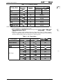
Table 1-13. Printing Speed
Printing Mode
Notes:
Ch~m&:er
(
Maximum Print Speed [cps]
Printable
Columns
Monochrome
Color
Draft
10 cpi
80
220 (165)
165 (1 65)
Draft
12 cpi
96
264 (198)
198 (198)
Draft condensed
17.1 cpi
137
188 (141)
Draft condensed
20 cpi
160
220 (165)
Draft emphasized
10 cpi
80
110 (83)
Draft double width
5 cpi
40
110 (83)
NLQ
10 cpi
80
44 (33)
NLQ
12 cpi
96
53 (40)
NLQ double width
5 cpi
40
22 (16)
.
i
‘x:
,:’
Data in parentheses indicates the speed on a line containing at least one of the following:
- A line containing a userdefined character.
- A linecontaining oneofthe50 characters corresponding tohexcodes BO to DFand F4
and F5.
- A line that is printing when printhead driving voltage drops from over-duty printing.
(When voltage drops below the lower limit, the printer stops printing in the middle of
the line, and then prints the rest of the line at a slower speed.)
Table 1-14. Resolution
Horizontal Density
Vertical Density
Adjaoent Dot Print
Draft
120 dpi
72 dpi
No
Draft condensed
240 dpi
72 dpi
No
Draft emphasized
120 dpi
72 dpi
Yes
NLQ
240 dpi
144 dpi
No
60 dpi
72 dpi
Yss
72 dpi
72 dpi
Yes
80 dpi
72 dpi
Yes
90 dpi
72 dpi
Yes
120 dpi
72 dpi
Yes
120 dpi
72 dpi
No
240 dpi
72 dpi
No
Printing Mode
Bit image
1-10
~.:?”;,
‘---
Rev. A
Prvduct Description
LX-3(3O Service Manual
1.3 INTERFACE SPECIFICATIONS
has parallel interface and serial interface, one of which can be selected in default setting
mode. Auto selection is also available.
LX-300
1.3.1 Parallel Interface Specifications
The LX-300 is equipped with an 8-bit parallel interface, standard.
Data format:
8-bit parallel
Synchronization:
By SIROBE pulse SyIIChrOIliZZItiOll
Handshaking:
By BUSY and ACKNLG signals
Signal level:
TTL-compatible level
Adaptable comectm
%-pm 57-30360 (Amphenol) or equivalent
Data transmission timing:
See Figure 1-7.
BUSY
ACKNLG
DATA
S T R O B E
——
—
h
0.5 ps (minimum)
0.5 ps (minimum)
0.5 IIS (minimum)
Figure 1-7. Data Transmission Timing
Note:
Transition time (rise time and fall time) of every input signal must be less than 0.2 M.
The Busy signal is active (HIGH) under the following conditions:
- During data reception (See Figure 1-7.)
- When the innt buffer is full
- When the INIT input signal is active
- During initialization
- When the ERROR signal is active
- During the self-test mode
- During the default-setting mode
The ERROR signal is active (LOW) under the following conditions:
- When a paper-out error occurs
- When a release lever operation error occurs
- When a fatal error occurs
The PE signal is active (HIGH) under the following conditions:
- When a paper-out error occurs
Rev. A
1-11
I
~s and signal functions for the 8-bit parallel interface.
-1 . . .
Pin Assignments for Parallel Interface
.
—.
[
}.. .
I
Description
I
~
The STROBE pulse is used to read the input
data. The pulse width must be more than 0.5 p.s.
Input data is latched after the falling edge of this
signal.
I
Parallel input data to the printer.
A HIGH level means data 1.
A LOW level means data O.
This pulse indicates data has been received and
the printer is ready to accept more data. The
pulse width is approximately 12 pa.
i
HIGH indicates the printer cannot accept more
data.
HIGH indicates rm~er-out. This signal is effective
only when the ERROR signal is LOW.
Always HIGH output. (Pulled up to +5V through
3.3 KQ resistor.)
I
!.
1-
.
f
L
If the signal is LOW when the printer is initialized
a line feed is automatically petformecf upon
receipt of the CR code (auto LF).
1
Not USed.
1
...
..
Signal ground.
—.
Chassis ground.
In the printer, chassis ground and signal ground
are short-circuited.
--
A HIGH level means that printer power is on.
.—
—
Signal ground.
,,
Input for printer initialization. Pulse width 50 ~
minimum, active LOW.
— .-. . ..—
LOW indicates that some error has occurred in
the printer.
Signal ground.
-..
.
.: . ! .
Pulled up to +5V through 1 KQ resistor.
Ignored.
. .
.,,~ ~ • .,f$e s@f@ as viewed from the @ter.
,,
. .
Rev. A
Product Description
LX-3(IO Service Manual
1.3.2 Serial Interface Specifkations
The LX-300 is equipped with an 8-bit serial interface, standard.
Data format:
EIA-232D serial
Synchronization:
Asynchronous
Handshaking:
By DTR signal and X-ON/X-OFF protocol
DTR and X-OIVX-OFF Protocol
Buffer Space
State
DTR
X-OWX-OFF
Busy
Less than 256 bytes
off
X-OFF
Ready
More than 512 bytes
On
X-ON
ETX/ACK Protocol
Buffer Spaoe
State
Response Code
Busy
Less than 256 bytes
NAK
Ready
256 bytes or more
ACK
Word length
Start bits:
Data bits:
Parity bit:
Stop bits:
Bit rate:
1 bit
7 or 8 bit (selectable)
O or 1 bit (selectable)
1 bit (transmitting)
1 bit or more (receiving)
300, 6(X), 1200,2400,4800,9600, 19200 bps (selectable)
Logic level
MARK (logical 1):
SPACE (logical O):
–3 V to –25 V
+3 v to +-25 v
Parity check:
Odd, even, or no parity bit (selectable)
Connector:
EIA standard 25-pin D-SUB female comector
Table 1-16. Signal and Connector Pin Assignments for Serial Interface
Pin No.
Signal Name
110*
1
FG
—
Chassis ground.
2
TXDJSD
out
Transmit seriil data.
3
RXDIRD
In
Receive serial data.
4
RTS/RS
out
This signal is always at the positive EIA level.
5
CTSVCS
Ignored.
7
SG
In
—
11,20
DTWER
out
This signal is at the positive EIA level when the printer is
ready to accept data entry and at the negative EIA level
when the printer is not ready to accep t data entry.
6,8-10,1219,21-25
NC
—
No connection (not used).
●
Description
Return path for data and control signals.
The //0 column irxbtes the djrectkm d the sjgnal as vjewed from the printec
Rev. A
1-13
UiWtJ Service Mhnual
Product Description
1.4 OPERATING INSTRUCTIONS
This section describes control panel operation ~ctions,
demonstration functions, and printer initialization methods.
self-test,
hexadecimal
dump,
.“ “II
~n
~~
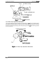
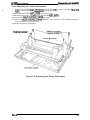
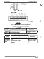
1.4.1 Control Panel Operation
The printer control panel contains three non-lock-type push buttons and three LED indimtors for
easy operation of the various printer functions.
Buttons
Lights
Light
A
/
/
Roman O O
Font
Saris SerifO ●
Draft.
Draft
o
Condensed.
●
● I
2
I W W Micro Adjust
o
Q
3sec
,, .
L
Figure 1-8. Panel Apperance
Paper Feeding
Load:
Press the LF/FF button.
Load (manual insertion):
Line feed:
Press the LF/FF button or the printer waits 2 seconds after insertion
of a cut sheet to load paper automatically.
Press the LF/FF button once.
Eject cut sheet:
Hold down the LF/FF button continuously.
Form feed (continuous):
Hold down the LF/FF button continuously.
Paper park (continuous):
Press the FONT and LF/FF buttons at the same time.
Tear-off (continuous):
Only uses auto tear-off function.
Character Selection
Font selection:
Press the FONT button.
Pitch selection:
Selectable indefault-setting mode: 10 cpi. or 12 cpi.
Condensed selection:
Press the FONT button. Only draft condensed is selectable.
~..,,
.
Enter Speaal Mode
Self-test mode:
Hold down the LF/FF button and turn on the printer.
Default-setting mode:
Hold down the FONT button and turn on the printer.
Hex dump mode:
Hold down the LF/FF and FONT button and turn on the printer.
Demonstration mode:
Not available.
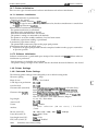
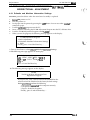
1.4.2 Self-test Function
This section explain how to run the self-test.
1.
Hold down the LF/FF button and turn on the printer to start the self-test.
2. If paper is not loaded, the printer attempts to load it.
3. If the printer camot load paper, it indicates this by turning on the PAUSE light. In this case,
insert paper again and press the LF/FF button.
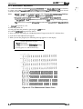
4. The printer prints alphanumeric characters continuously.
5. Quit self-test mode printing by pressing the PAUSE button and turning the printer off.
1-14
Rev. A
Pfvduct LMacription
LX#O Service Manual
1.4.3 Hexadecimal Dump Function
The hexadecimal dump is a useful tool for troubleshooting data control problems. This section
describes how to run a hex dump.
1.
Turn on the printer while holding down the LF/FF and FONT buttons.
2. If paper is not loaded, the printer attempts it (either single sheet or continuous paper).
3. If the printer cannot load the paper, it indi~tes a paper-out error. In this case, insert paper
again, and press the PAUSE button.
4. The printer waits for data after printing the message “Hex dump.”
5. Received data is printed as both hexadecimal codes and ASCII characters. If a corresponding
printable character does not exist, the printer outputs a period (.).
6. Quit hexadecimzd dump printing by pressing the PAUSE button and tumingtheprinter off.
Note:
In hex dump mode, the character table depends on the default settin& and 10 cpi draft is
selected automatically.
1.4.4 Printer Status Indication
It describes how this printer indicates status and error conditions using LEDs and the beeper.
The symbols below describe the frequency of beeper sounds.
( ● ):
The beeper sounds tbr 100 rns with an interval of 100 ms between beeps.
(—): The beeper sounds for5~mswithan interval of100ms between beeps.
While initialize signal is active:
During initialization:
Ready to print or printing:
Paper-out error:
Tear-off:
Operating error, fatal error:
PAUSE light is on.
PAUSE light blinks and beeper sounds
PAUSE light is off
Beeper sounds ( ● ● . ) and PAUSE light blinks.
(light on:off ratio= 6:1)
PAUSE light blinks (light on:off ratio= 1:6)
Beeper sounds ( ————— ) and PAUSE light is on.
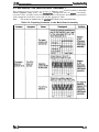
1.4.5 Selected Font
The combination of two FONT LEDs (1 and 2) is used to indicate the selected font.
Table 1-17. Font Selection
FONT 1
FONT 2
Roman
ON
ON
Saris Serif
ON
OFF
Draft
OFF
ON
Draft condensed
OFF
OFF
Selected Font
1.4.6 Paper Position Adjustments
To enter adjustment mode, press the PAUSE button for three seconds, until the printer beeps once
and the FONT lights blink to indicate that the adjustment operation is available. If the printer state
is not one of the conditions shown below, this operation is ignored.
. TOF position adjustment:
The position mn be adjusted just after the paper is loaded.
. Tear-off position adjustment:
The position can be adjusted when paper is actually located at the tear-off position.
In the adjustment mode, press the LF/FF button to feed paper forward and the FONT button to
feed paper backward. You can cancel adjustment mode bypressingthe PAUSE button or inputting
a print command. The adjusted position is stored in non-volatile memory.
Rev. A
1-15
LXiWO Service Manual
Product Description
1.4.7 Printer Initialization
There are two types of initialization: hardware initialization and software initialization.
1.4.7.1 Hardware Initialization
Hardware initialization is performed by:
. Turning on the printer.
. Sendiny@e parallel interface the~signal.
(If the INIT signal is active when the printer is turned on, hardware initialization is started when
the ~ signal becomes imctive.)
When hardware initialization is performed:
. The printer mechanism is initialized.
. Print data in the input buffer is cleared.
. Download character definitions are cleared.
. The printer’s settings are returned to the defaults.
. The printer is set to the standby condition, if no fatal error occurs.
. Continuous paper home-seeking is performed.
In continuous paper home-seeking:
. The printer feeds continuous paper to the paper park position.
● The printer then loads the paper again.
●
If ejection to the paper park position cannot be completed within 16 inches, paper is returned to
its previous position.
1.4.7.2 Software Initialization
Software initialization is performed upon receipt of the control code ESC C?. When software
initialization is performed:
. Print characters in the buffer are not cleared.
. The printer setting is changed to the default, but the download character definition is not cleared.
1.4.8 Printer Settings
1.4.8.1 Selectable Printer Settings
The following printer settings can be changed by users in default-setting mode:
Character spacing:
.lQc@ / 12cpi
Shape of zero:
Slashed / Not slashed
... ~?
.....
1 inch skip-over-perforation: on/Qff
Auto line feed:
on/Qff
Character table (Standard):
Character table (NLSP):
Italic (JJSA/France/Germany/UK/Denmark l/Sweden/Italy/
Spain 1)/PC437/850/860 /861/863 /865/BRASCII/Abicomp
Italic &?SA/France/German y/UK/Denmar k l/Sweden/Italy/
Spain 1)/KG7/~/S2/8S/E5 /857/=/869/07 Greek/ISO
Latin IT /1S0 8859-7/Code MJK/Mazowia/Bulgaria
Page length:
11/ 12/ 8.5 / 70/6 inches
Auto tear off:
on/Qff
Tractor:
Single / Double
interface:
~/ Auto selection (30 sec wait) / Parallel
/ Serial
Bit rate (serial I/F):
300 / 600/ 12(MI / 2400 / 4800 / $?6Ul / 19200 bps
Parity bit (serial I/F):
Mm/ Odd / Even
Data length (serial I/F):
Z.Ms / 8 bits
ETX/ACK (serial I/F):
~ / Enabled
Note:
1-16
Underlines show factory setting.
Rev. A
Product Description
LX-300 Service Manual
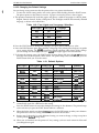
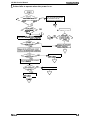
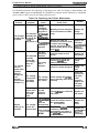
1.4.8.2 Changing the Default Settings
You can change some parameters that the printer refers to at printer initialization.
1.
To enter the default setting mode, turn on the printer while holding down the FONT button.
The printer prints out the firmware version. If paper is not loaded, insert a sheet of paper.
2. The printer automatically loads the paper and prints a table of languages to choose from:
English, French, German, Italian, and Spanish. The Footlights indicate the currently selected
language, as shown in the table below.
Table 1-18. Font Lights and Language Selection
Language
FONT Light 1
FONT Light 2
OFF
ON
English
OFF
Blinks
French
ON
OFF
German
ON
ON
Italian
ON
Blinks
Spanish
3. Press the FONT button to change the language, and press the LF/FFbutton to select.
4. Press the FONT button again after selecting a language. The printer prints help text to guide
you in setting defaults. The pMted instructions include submenu tables listing all the settings
you can change and showing you how the mntrol panel lights appear for each selection.
5. To change the settings, press the FONT button to move down and press the LF/FF button to
move up in the menu of options shown below. The printer beeps once each time you press the
FONT button while you are in this menu.
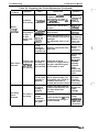
Table 1-19. Default Options
FONT Light 1
6.
7.
8.
9.
FONT Light 2 PAUSE Light
Setting
Submenu
Blinks
OFF
OFF
Character spacing
Table 1-20
Biinks
ON
OFF
Shape of zem
Table 1-21
OFF
Biinks
OFF
Skip over perforation
Table 1-22
ON
Blinks
Blinks
Blinks
OFF
OFF
Character table
Auto line feed
Tabie 1-23
Tabie 1-24
Biinks
Blinks
OFF
ON
ON
Page iength
Table 1-25
ON
Auto tear off
Tabie 1-26
OFF
ON
Blinks
OFF
Blinks
ON
ON
ON
Table 1-27
Biinks
Tractor
Interface
Bit rate
Parity
Biinks
ON
OFF
OFF
Biinks
Data length
Biinks
ETWACK
Tabie 1-31
Table 142
Blinks
Biinks
OFF
Table 1-28
Table 1-29
Table 1-30
When you reach the setting you want to change, press the PAUSE button once. The printer
automatically enters the submenu for that setting.
Press the FONT button to move the through the settings in the submenu. The printer beeps
twice each time you press the FONT button while in a submenu.
When the lights match your desired settin~ press the PAUSE button to make your selection.
The printer saves the new setting and returns to the menu shown above.
Repeat steps 5 through 8 for each additional setting you want to change, or skip to step 10 to
exit the printer’s defauit setting mode.
10. When you are finished, turn the printer off. Any settings you have made remain in effect until
you change them again.
Rev. A
1-17
LX300 Service M%ual
Product Description
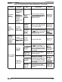
Table 1-20. Character Spacing
Character Spacing
FONT Light 2 PAUSE Light
FONT Light 1
OFF
OFF
OFF
10 cpi
ON
ON
ON
12 cpi
A
Table 1-21. Shape of Zero
FONT Light 1
FONT Light 2
PAUSE Light
Space of Zero
OFF
OFF
OFF
o
ON
ON
ON
0
Table 1-22. Skip Over Perforation
FONT Light 1
FONT Light 2 PAUSE Light
SkipOver-Petioration
OFF
OFF
OFF
No Skip
ON
ON
ON
skip
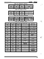
Table 1-23. Character Table
FONT Light 1
FONT Light 2 PAUSE Light
Standard Table
NLSP Table
OFF
OFF
OFF
Italic — US
Italic — US
ON
OFF
OFF
Italic — France
Italic — France
Blinks
OFF
OFF
Italic — Germany
Italic — Germany
OFF
ON
OFF
Italic — UK
Italic — UK
ON
ON
OFF
Italic — Denmark 1
Italic — Denmark 1
Blinks
ON
OFF
Italic — Sweden
Italic — Sweden
OFF
Blinks
OFF
Italic — Italy
Italic — Italy
Blinks
Blinks
OFF
Italic — Spain 1
Italic — Spain 1
OFF
OFF
ON
Pc 437
Pc 437
ON
OFF
ON
PC 850
PC 850
Blinks
OFF
ON
PC 860
PC 852
OFF
ON
ON
Pc 861
PC 853
ON
ON
ON
PC 863
Pc 855
Blinks
ON
ON
PC 865
PC 857
OFF
Blinks
ON
BRASCII
PC 866
ON
Blinks
ON
PC 869
Blinks
Blinks
ON
Abicomp
—
PC 437 Greek
OFF
OFF
Blinks
—
ISO Latin IT
ON
OFF
Blinks
—
1s0 8859-7
Code MJK
Blinks
OFF
Blinks
—
OFF
ON
Blinks
—
Mazowia
Blinks
—
Bulgaria
ON
OFF
1
.,
1-18
Rev. A
Product Lkactiption
LX-3(IO Service Manual
Table 1-24. Auto Line Feed
Auto Line Feed
FONT Light 1 FONT Light 2 PAUSE Light
OFF
OFF
OFF
off
ON
ON
ON
On
Table 1-25. Page Length
Page Length
FONT Light 2 PAUSE Light
FONT Light 1
ON
OFF
OFF
11 inches
OFF
ON
OFF
12 inches
ON
ON
OFF
8.5 inches
OFF
OFF
ON
70/6 inches
Table 1-26. Auto Tear Off
FONT Light 1
FONT Light 2
PAUSE Light
Auto Tear Off
OFF
OFF
OFF
off
ON
ON
ON
On
Table 1-27. Tractor
FONT Light 1
FONT Light 2
PAUSE Light
Tractor
OFF
OFF
OFF
Single
ON
ON
ON
Double
Table 1-28. Interface
Interface
FONT Light 1 FONT Light 2 PAUSE Light
ON
OFF
OFF
Auto selection (10 me wait)
OFF
ON
OFF
Auto selection (30 rns wait)
ON
ON
OFF
Parallel
OFF
OFF
ON
Serial
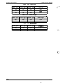
Table 1-29. Bit Rate
FONT Light 1
Bit Rate
ON
OFF
OFF
300 b~
ON
ON
OFF
600 bps
ON
ON
OFF
1200 bps
OFF
OFF
ON
2400 bps
ON
Rev. A
FONT Light 2 PAUSE Light
I
OFF
I
ON
I
4800 tx)s
OFF
ON
ON
9600 bps
ON
ON
ON
19200 bps
1-19
U-300 Service Manual
Product Description
Table 1-30. Parity Bit
FONT Light 1
FONT Light 2
PAUSE Light
Parity Bit
ON
OFF
OFF
None
ON
ON
OFF
ON
ON
OFF
((’’”
Even
Table 1-31. Data Length
,
FONT Light 1
FONT Light 2
PAUSE Light
Data Length
OFF
OFF
OFF
7 bits
ON
ON
ON
8 bits
Table 1-32. ETX/ACK
FONT Light 1
FONT Light 2
PAUSE Light
ETX/ACK
OFF
OFF
OFF
off
ON
ON
ON
On
~ .,....,
,. ..,,-,.
1-20
Rev. A
,.
Ptvduct Daactiption
LX-3(IO Sarvice Manual
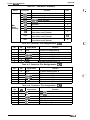
1.5 MAIN COMPONENTS
The
main components of the LX-300 is designed for easy removal and repair. The main
components are;
■ C130 MAIN BOARD: Control board
■ C130 PSB/PSE (120V / 220-240V) BOARD: Power supply board
■ M-3G1O: Printer mechanism
9 Housing
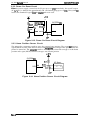
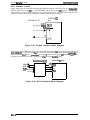
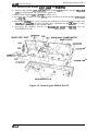
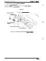
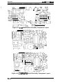
1.5.1 C130 MAIN Board
The C130 MAINboard consists of an E01A09 (CPU), a Program/CG ROM, a RAM, an EEPROM,
etc.
PROM
(Program 1 CG)
E01A09 (CPU)
\
/- 2SC5~
000 00 >
(Printhead Driver)
2SC5060
(PF MOTOR Driver)
I
y
/’
00
000
0
n—
0 %
0
UPC78M05AHF
SLA7022M
(CR MOTOR
(Regulator IC)
DRIVER)
SUB PCB
(COLOR OPTION)
Figure 1-9. C130 MAIN Board Component Layout
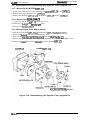
1.5.2 C130 PSB/PSE Board
The C130 PSB/PSE power supply board consists of a transformer, switching FETs, regulate IC,
diode bridge, etc. This board has two ratings for input AC voltages.
Diodde Bridge
Switching FET
Power Switch
Transformer
Fuse
0
❑
o
0
/
“
)
\
Regulater IC
Figure 1-10. C130 PSB/PSE Board Component Layout
1-21
Rev. A
,,
(
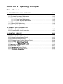
CHAPTER 2 Operating Principles
Table of Contents
2-1
2.1 PRINTER MECHANISM OPERATION
2.1.1 Printing Mechanism. . . . . . . . . . . . . . . . . . . . . . . . . . . . . . . . . . . . . . . . . 2-1
2.1.2 Carriage Movement Mechanism . . . . . . . . . . . . . . . . . . . . . . . . . . . . . . . 2-2
2.1.3 Paper Handling Mechanism. . . . . . . . . . . . . . . . . . . . . . . . . . . . . . . . . . . 2-3
2.1.3.1 Paper Feed Mechanisms. . . . . . . . . . . . . . . . . . . . . . . . . . . . . . . 2-3
2.1.3.2 Paper Advance Mechanism. . . . . . . . . . . . . . . . . . . . . . . . . . . . . 2-3
2.1.4 Ribbon Advance Mechanism . . . . . . . . . . . . . . . . . . . . . . . . . . . . . . . . . . 2-7
2.1.5 Ribbon Shift Mechanism . . . . . . . . . . . . . . . . . . . . . . . . . . . . . . . . . . . . . 2-8
2.1.6 Platen GapAdjustment Mechanism . . . . . . . . . . . . . . . . . . . . . . . . . . . . 2-9
2-1o
2.2 POWER SUPPLY OPERATION
2.2.1 Power SupplyOvefview. . . . . . . . . . . . . . . . . . . . . . . . . . . . . . . . . . . . . 2-10
2.2.2 Power Supply Circuit Operation. . . . . . . . . . . . . . . . . . . . . . . . . . . . . . . 2-11
2-12
2.3 CONTROL CIRCUIT
2.3.1 Control Circuit Operation Overview. . . . . . . . . . . . . . . . . . . . . . . . . . . . 2-12
2.3.2 Power On Reset Circuit. . . . . . . . . . . . . . . . . . . . . . . . . . . . . . . . . . . . . 2-13
2.3.3 Home Position Sensor Circuit . . . . . . . . . . . . . . . . . . . . . . . . . . . . . . . . 2-13
2.3.4 Paper End Sensor Circuit . . . . . . . . . . . . . . . . . . . . . . . . . . . . . . . . . . . 2-14
2.3.5 Release Lever Position Sensor Circuit . . . . . . . . . . . . . . . . . . . . . . . . . 2-14
2.3.6 Carriage MotorDriveCircuit . . . . . . . . . . . . . . . . . . . . . . . . . . . . . . . . . 2-15
2.3.7 Paper Feed MotorDriveCircuit . . . . . . . . . . . . . . . . . . . . . . . . . . . . . . . 2-16
2.3.8 Printhead Drive Circuit. . . . . . . . . . . . . . . . . . . . . . . . . . . . . . . . . . . . . . 2-16
2.3.9 Interface Circuit.. . . . . . . . . . . . . . . . . . . . . . . . . . . . . . . . . . . . . . . . . . 2-17
2.3.10 EEPROM Control Circuit. . . . . . . . . . . . . . . . . . . . . . . . . . . . . . . . . . . 2-18
2.3.11 CSMotorAssembly Circuit . . . . . . . . . . . . . . . . . . . . . . . . . . . . . . . . . 2-18
2.3.12 Color Ribbon SensorCircuit . . . . . . . . . . . . . . . . . . . . . . . . . . . . . . . . 2-19
List of Figures
Figure 2-1. iSrintheadoperation principles . . . . . . . . . . . . . . . . . . . . . . . . . . . . z-l
Figure 2-2. [:arriage Movement Mechanism . . . . . . . . . . . . . . . . . . . . . . . . . . . 2-2
Figure 2-3. IFriction Advance Mechanism. . . . . . . . . . . . . . . . . . . . . . . . . . . . . . 2-3
Figure 2-4. I~ush Tractor paper Advance Mechanism . . . . . . . . . . . . . . . . . . . . 2-4
Figure 2-5. Ipu~Tractor paper Advance Mechanism . . . . . . . . . . . . . . . . . . . . . 2-5
Figure 2-6. IPush-Pull Tractor PaperAdvance Mechanism . . . . . . . . . . . . . . . . . 2-6
Figure 2-7. IPaper Path. . . . . . . . . . . . . . . . . . . . . . . . . . . . . . . . . . . . . . . . . .. .2-6
Figure 2-8. IRibbon Advance Gear Linkage . . . . . . . . . . . . . . . . . . . . . . . . . . . . 2-7
Figure 2-9. (ColorShift Mechanism.. . . . . . . . . . . . . . . . . . . . . . . . . . . . . . . . . . 2-9
Figure 2-10 Platen GapAdjustment Mechanism . . . . . . . . . . . . . . . . . . . . . . . . 2-9
Figure 2-11 Power Supply Circuit Block Diagram . . . . . . . . . . . . . . . . . . . . . . 2-11
Figure 2-12 Control Circuit Block Diagram . . . . . . . . . . . . . . . . . . . . . . . . . . . 2-12
Figure 2-13 Power On Reset Circuit Diagram. .,..... . . . . . . . . . . . . . . . . . 2-13
Figure 2-14 HomePositionSensorCircuit Diagram . . . . . . . . . . . . . . . . . . . . 2-13 ,.
Figure 2-15. PaperEndSensor Circuit Diagram . . . . . . . . . . . . . . . . . . . . . . . 2-14
(f
‘ K..d
Figure 2-16 Release Lever Position Sensor Circuit Diagram . . . . . . . . . . . . . 2-14
Figure 2-17 Carriage Motor DriverCircuit Diagram . . . . . . . . . . . . . . . . . . . . . 2-15
Figure 2-18 Paper Feed Motor DriverCircuit Diagram . . . . . . . . . . . . . . . . . . 2-16
Figure 2-19 Printhead Driver Circuit Diagram . . . . . . . . . . . . . . . . . . . . . . . . . 2-16
Figure 2-20 Parallel Interface Block Diagram . . . . . . . . . . . . . . . . . . . . . . . . . 2-17
Figure 2-21. Serial interface Block Diagram . . . . . . . . . . . . . . . . . . . . . . . . . . 2-17
Figure 2-22 EEPROM Control Circuit Diagram . . . . . . . . . . . . . . . . . . . . . . . . 2-18
Figure 2-23 CSMotorAssemblyCircuit Diagram . . . . . . . . . . . . . . . . . . . . . . 2-18
Figure 2-24 Color Ribbon SensorCircuit Diagram . . . . . . . . . . . . . . . . . . . . . 2-19
List of Tables
Table
Table
Table
Table
Table
Table
Table
Table
Table
2-1. CR Motor Assembly Specifications. . . . . . . . . . . . . . . . . . . . . . . . . . 2-2
2-2. PF Motor Assembly Specifications . . . . . . . . . . . . . . . . . . . . . . . . . . 2-4
2-3. Ribbon Advance Gear Linkage . . . . . . . . . . . . . . . . . . . . . . . . . . . . 2-7
2-4. CS Motor Assembly Specifications. . . . . . . . . . . . . . . . . . . . . . . . . . 2-8
2-5. Coloring Sequences . . . . . . . . . . . . . . . . . . . . . . . . . . . . . . . . . . . . . 2-8
2-6. Power Supply Board. . . . . . . . . . . . . . . . . . . . . . . . . . . . . . . . . . . . 2-10
2-7. Power Supply Output Voltages and Applications . . . . . . . . . . . . . . 2-10
2-8. Functions of the Main IC. . . . . . . . . . . . . . . . . . . . . . . . . . . . . . . . . 2-12
2-9. Carriage Motor Drive Modes. . . . . . . . . . . . . . . . . . . . . . . . . . . . . . 2-15
~ f=::,
-..
Operating Ptinciph3
LX-3(XI Service Manual
2.1 PRINTER MECHANISM OPERATION
l%is section describes the M-3G1O printer mechanism and explains how it works.
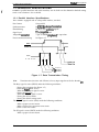
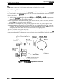
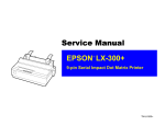
2.1.1 Printing Mechanism
The printer mechanism is composed of the printhead, ink ribbon, and ribbon mask. The printhead
is a 9-pin head for impact dot printing. Each wire has own drive coil, which causes the wire to
move in and out of the printhead to print each dot. The four steps below describe how these
driving wires work.
1.
A drive signal transmitted from the control arcuit to the printhead drive arcuit is converted to
the proper printhead driving voltage, which energizes a corresponding coil. The energized coil
then causes the iron core to become magnetized.
2. The magnetic force draws the actuating plate toward the core, and the dot wire, which is
comected to the core, rushes toward the platen.
3. When the dot wire impacts the platen, pressing against the ribbon and paper, it prints a dot.
4. When the driving voltage stops energizing the coil, the magnetic force from the iron core
vanishes. The actuating plate returns to its original position (the position betbre coil was
energized) with spring action. The dot wire also returns to its original position.
This is the sequence used to print a single dot.
The mechanism is equipped with a built-in thermistor for head temperature detection. The
temperature detected by the thermistor is converted to an electric signal and fed back to the control
circuit.
Wire Resettin S rin
Stopper
Dot Wire
T’Y____
r
\Actuating Spring
Figure 2-1. Printhead Operation Principles
Rev.A
2-1
LX-WI Service Mimual
Operating Principles
2.1.2 Carriage Movement Mechanism
The carriage movement mechanism consists of the carriage assembly, CR motor assembly, timing
belt, driven pulley, HP sensor, etc. The CR motor assembly drives tie tifig belt. me carriage
assembly is comected to the timing belt, which is moved by the CR motor assembly. Figure 2-2
shows the carriage movement mechanism.
The printer detects the carriage home position with the HP sensor. This sensor is the basis for
determining the carriage home position. The HP sensor informs the CPU of the carnage home
position. The sensor is ON, when the carriage is pushed to the right or left. The striker on the
carriage actives the sensor to indicate the carriage home position, which toggles the sensor to OFF.
Table 2-1. CR Motor Assembly Specifications
Requirement
Category
Type
4-phase, 48-pole, PM-type stepping motor
Drive Voltage
31.5 -38.5 VDC
Coil Resistance
180 ohms * 7Y0 (per phase, at 25° C, 77° F)
1320 p~
Normal Mode Draft
1980 PPS
Color Mode Draft
Constant-voltage
2-2 phase excitation
1-2 phase excitation
Drive Pulse Frequency
Excitation Method
CARRIAGE ASSY.,
TIMING BELT
.,,CR
Figure 2-2. Carriage Movement Mechanism
2-2
Rev.A
Operating Principla
LX-300 Sewica Manual
2.1.3 Paper Handling Mechanism
During normal operation, the paper is fed to the printer, advanced to the specified position, and
ejected from the printer. These paper handling operations are performed by various paper
handling mechanisms, such as the tractors, rollers, and gears. This section describes the paper
handling mechanism for this printer.
2.1.3.1 Paper Feed Mechanisms
Cut sheets are fed by friction. Continuous paper is fed by a tractor. There are three ways to feed
with tractors: the push tractor method, the pull tractor method, and the push-pull tractor method.
During normal operation, the printer is set up with only one tractor, which functions as either a
push or a pull tractor, depending on where it is attached on the printer. To use the push-pull
tractor feed method, an optional tractor must be attached.
There are two ways to insert paper into the printer. Cut sheets use the top entrance and continuous
paper use rear insertion.
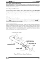
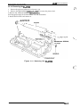
2.1.3.2 Paper Advance Mechanism
This section describes how the friction and tractor advance mechanisms feed paper through the
printer. The paper advance mechanism consists of the PF motor assembly, platen, dtiven roller
assembly, driven roller cover, tractor assembly, knob, PF gear train, etc. The PF motor assembly
can drive the platen both forward and in reverse.
Friction Advance Method
Paper is held by the platen, the PF driven roller, and the eject roller assembly. Turning in the
direction of the black arrows, the PF motor assembly pinion gear drives the paper advance
reduction gear. The paper advance reduction gear turns the platen gear, PF driven roller, and the
platen. The platen drives the driven roller cover; then the driven roller cover drives to eject the
paper. The paper advances in the direction of white arrows. Figure 2-3 shows the friction advance
method when the paper is fed through the top paper entrance.
COVER, ROLLER, DRIVEN
,,
PAPER ADVANCE
REDUCTION GEAR
MOTOR ASSY.,PF
ROLLER, PF,DRIVEN
PLATEN GEAR
Pinion Gear
Figure 2-3. Friction Advance Mechanism
Rev.A
2-3
LX-300 Service Manual
Operating Principles
Table 2-2. PF Motor Assembly Specifications
Requirement
Categov
Type
4-phase, 48-pole, PM-type stepping motor
Drive Voltage
31.5 -38.5 VDC
Coil Resistance
56 ohms f 5Y0 (per phase, at 25°C, 77°F)
Drive Pulse Frequency
800,900,1000,1200,1300 pps
Excitation Method
Constant-voltage 1-2 phase excitation
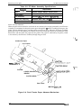
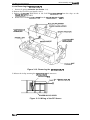
Push Tractor Method
When the push tractor method is used with the rear entrance, the torque generated by the PF motor
assembly is transmitted to the push tractor gear through the PF motor assembly pinion gear, the
paper advance reduction gear, and the tractor transmission gear. When the PF motor assembly
pinion gear turns in the direction of the black arrows, the tractor gear rotates in the direction of the
black arrow and thus feeds the paper into the printer. The paper is advanced by the platen, which
is also driven by the PF motor assembly through the gear train.
(’*.,-,
Continuous Paper
/
Push
Tractor
,,
\
. . . . .~’v
. . .I tb I UH
,r~
“.
r
-
PLATEN
COVER, ROLLER,
DRIVEN
PLATEN GEAR
Pinion Gear
MOTOR ASSY.,PF
Figure 2-4. Push Tractor Paper Advance Mechanism
2-4
Rev.A
-
Operating Ptincipla
LX-300 Sarvica Manual
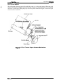
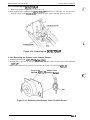
Pull Tractor Method
The pull tractor advances paper in basically the same way as the push tractor. When the push
tractor is installed at the paper exit instead of paper entrance, the tractor functions as a pull tractor
instead of a push tractor, pulling the paper out of the printer mechanism. Figure 2-5 shows the pull
tractor advance mechanism.
Continuous Paper
,
-.
R
PL
.,PF
Figure 2-5. Pull Tractor Paper Advance Mechanism
Rev.A
2-s
U400 Smdce Manual
Operatjng Prjncjples
Push - Pull Tractor Method
The push-pull tractor method is a combination of the push method, using the standard tractor, and , ~’ “
the pull method, using an optional tractor. The two traders operate simultaneously to push and
pull the paper through the printer mechanism. Figure 2-6 shows push-pull tiadoroperation when
the paper is fed through the rear paper entrance.
~.i ,
..
Figure 2-6. Push-Pull Tractor Paper Advance Mechanism
Disengage Lever
The disengage lever switches whether or not the printer transmits the torque of the PF motor
assembly to the tractor transmission gear. (See Figures 2-5 and 245.)
The paper path is different from friction feed and tractor feed. The PF driven roller is not in the
tractor feed paper path, so continuous paper is not advanced by this roller. F@me 2-7 shows the
paper path.
SHEET GUIDE
-> Cut Sheet
PLATEN
Continuous paper
QY
;&TRAcTOR
/
ROLLER, PF, DRIVEN
‘ DETECTOR ASSY., PE
Figure 2-7. Paper Path
,.
24
Rev.A
Operating Principb
LX~lW Service Manual
2.1.4 Ribbon Advance Mechanism
The ribbon is held between the ribbon advance roller (ribbon driven gear) and the ribbon pressure
roller. When the carriage moves on the CR guide shaft from left to right and vice versa, the timing
belt turns the belt driven pulley. Then the torque is transmitted to the ribbon driving gear through
the gear trains. The ribbon driving gear rotates counterclockwise no matter what direction the
carriage moves, because a planetary gear is used in the gear linkage.
Table 2-3. Ribbon Advance Gear Linkage
1
Direction of Carriage Movement
Gear Linkage
I
Left to right
(indicated by the black arrow)
Belt driven pulley + Gear(1)+ Gear (2)+
Ribbon driving gear
Right to light
indicated by the white arrow)
Belt driven pulley + Gear(1) -+ Gear (3)+
Gear (4) + Ribbon driving gear
The ribbon brake sprina attached to the exit of the cartridge case, prevents slack in the ribbon and
keeps the ribbon tension at an appropriate level. The ribbon mask prevents the ribbon from
brushing against the paper.
Ribbo
Ribbon
Spring
Figure 2-8. Ribbon Advance Gear Linkage
Rev.A
2-7
LX-300 Service Manual
Operating Principles
2.1.5 Ribbon Shift Mechanism
This printer can be equipped with a color upgrade kit to print in color. The printer performs color
printing unidirectionally. The option is composed of the color ribbon shift mechanism. The Color
ribbon feed mechanism is shared in common with black ribbon feed mechanism, and the shift
mechanism shifts the ribbon cartridge up and down.
Table 2-2 shows the CS motor assembly specifications. The motor control system is open-loop, so
that when the color is being changed, the positioning is controlled by stepping pulse.
Table 2-4. CS Motor Assembly Specifications
Requirement
Category
Type
4-phase, 48-pole, PM-type stepping motor
Drive Voltage
35 VDC * 10Yo
Coil Resistance
150 ohms f 5Y0 (per phase, at 25° C or 77° F)
Drive Pulse Frequency
Color shift 500 pps
Excitation Method
Constant-vottage 2-2 phase excitation
The ribbon shift mechanism consists of the color ribbon and color upgrade kit. The color upgrade
kit is composed of the CS motor assembly, ribbcm shift gear/cam, motor driver IC, and color ribbon
sensor. The l-inch-wide color ribbon is separated into four equal-width bands of different colors.
The ribbon shift mechanism shifts the ribbon cartridge up and down.
When the color ribbon cartridge is loaded, it is possible to print in up to seven colors. One of the
four colors on the ribbon is selected by the color ribbon cartridge motion, which inserts a portion of
the plastic posts into the slots in the printer mechanism as a fulcrum. Figure 2-9 illustrates the color
shift mechanism. The mechanism shifts the ribbon cartridge by converting the gear rotation to
liner motion (up and down) of the color ribbon cartridge, using color shift cam gear.
Any color band can be selected by’ rotation of the CS motor assembly, using the color home
position (the position of the black color band) as a starting point and reference position. Home
position is recognized by the CS motor assembly stepping pulse. When printer is power on, the CS
motor assembly is exated at any phase position at first. Next, the CS motor assembly is turned for
235 steps ( black + yellow). Then, the motor returns one step (yellow+ black), and the ‘motor is
stopped. Finally, the motor returns 223 steps (yellow+ black) and stops. This position is home
position.
Table 2-5 gives coloring sequences. For halftones, as shown in the table, a color is created by
printing one color on top of another.
f-’””,.
Table 2-5. Coloring Sequences
Print Ribbon
Print Color
Note:
2-8
First Printing
Seoond Printing
Black
Black
—
Magenta
Magenta
—
Cyan
cyan
—
Yellow
Yellow
—
Green
Yellow
cyan
Orange
Yellow
Magenta
Violet
Magenta
Cyan
The printer prints the brighter color first to prevent the ribbon from bt ng stained
Rev.A
Operating Pdncipb
LX-300 Service Manual
Color Ribbon Cartridge
Fulcrum
1/
LEVER,CS
-
-—-
HOLDER, CARTRIDGE,COLOR
Pinion of MOTOR ASSY.,CS
Color Shift Cam
Color Shift Cam Follower
Figure 2-9. Color Shift Mechanism
2.1.6 Platen Gap Adjustment Mechanism
‘The platen gap (the gap between the platen and the printhead) can be adjusted to allow the printer
to use paper of different weights or thicknesses. When the gap adjust lever is moved forward or
backward, the CR guide shaft rotates. This rotation moves the carriage either toward or away from
the platen and changes the platen gap. The correct platen gap is 0.45 tO.02 mm with the gap adjust
lever set to position O.
LEVER,G,ADJUST Motion
PG
, TL,
I I
1 \
,
,LEVER’GJADJUST
i’1 .*pfinthead
i$- “> printhad Motion”
F “-””l
5
Platen
“
\
a
. . — .
.“
SHAFT,CR,GUIDE
Figure 2-10. Platen Gap Adjustment Mechanism
Rev.A
2-9
LXXX) Service Mimual
Operating Principles
2.2 POWER SUPPLY OPERATION
powered by either of two power supply boards: the C130 F’SB (120V) board
assembly or the C130 PSE (230V) power supply. The function of these two boards is the same,
except for a difference in primary circuitry. The power supply board outputs the DC current
necessary to drive the printer control circuits and drive mechanism. Table 2-6 shows the input
voltages and fuse ratings for these boards.
The printer can be
( ( “+
Table 2-6. Power Supply Board
Board
Input Voltage
Fuse F1 Rating
C130 PSB
100.5-132 VAC
2.5A 1125V, 250V
C130 PSE
198-284 VAC
1.25A 1250V
2.2.1 Power Supply Overview
The power supply board has two power outputs for use in the various control arcuits and drive
mechanisms. Table 2-7 lists the circuitry and the units that are driven by the two DC output supply
voltages.
Table 2-7. Power Supply Output Voltages and Applications
‘I%$:i’ul’
Applications
CR motor drivers
+35 v (VP)
PF motor drivers
Printhead drivers
I CS rnotordrivers
I Main board assetivkxic arcuitw
+9 V (VL)
Various sensors
Control panel LED
PF motor/ CS motor hold
,,
.,. .
..
2-10
Rev.A
.
Operating Principk
LX300 Sarvica Manual
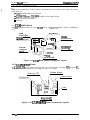
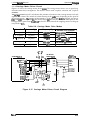
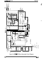
2.2.2 Power Supply Circuit Operation
Figure 2-11 shows a block diagram of the power supply circuitry. When AC power is supplied to
the printer from an external power source, a filter circuit removes the noise. l%e AC voltage then
undergoes full-wave rectification and is smoothed to produce the direct current supply voltage.
This voltage is fed through a switching circuit and secondary smoothing circuit to produce the
stepped down +35 VDC supply. A +35V line voltage detector (ZD51 and PCl) circuit is connected
to the switching arcuit. This feedback control arrangement ensures that the +35 VDC supply is
kept stabilized.
A +9 VDC supply is created by putting the +35 VDC line through the +9 VDC power supply
circuit. This arcuit further steps down the +35 VDC voltage and outputs a stabilized supply. The
+9 VDC output is stabilized to +5 VDC using the regulator on the C130 MAIN board assembly.
There are several arcuits to protect the supply arcuits and avoid danger.
The +9 VDC line contains a voltage overload protection circuit. The +9V voltage overload
protection circuit (ZD53, Q82, and PC1) cuts the supply if the voltage reaches or exceeds +11 VDC.
It stops switching circuit operation, which stops the output from the +35 VDC line.
‘he +35 VDC line has a voltage overload protectkm circuit. l’he +35 VDC voltage overload
protection circuit ( ZD52, Q82, and PC1 ) cuts the supply if the voltage reaches or exceeds +36 VDC.
It stops switching circuit operation, which stops the output from the +35 VDC line.
Full-Wave
Rectification —
Circuit
Smoothing
Circuit
Smoothing
CirciM
Switching
Circuit
o +35 VDC (VP)
D
Filter Circuit
Pflot&
Couplef
+9VDC
+
Sfabilizatial + + +9VDC (VL)
circuit
A
+3SVDC line
(— ~
)
AC Line
+9 VDC line
d — over-voltage
FMecthn
Circuit
—
+35 VDC line
OWr-volfaga
Protection
Cinxit
figure 2-11. Power Supply Circuit Block Diagram
Rev.A
2-11
LX-300 Service Manual
Operating Principles
2.3 CONTROL CIRCUIT
The control circuit consists of the C130 MAIN board assembly. This -on describes the major
components and explains how the board works.
( :“
2.3.1 Control Circuit Operation Overview
The printer’s system IC contains a CPU (pPD78C10A-type) that mm at 14.74 MHz, a gate array
(E05A79-type) and a main RAM ( 8KB SRAM). It oversees control of all the components in the
printer. The printer uses the E05A90 gate array to control address decodins parallel
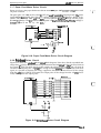
communidion.s, PF motor drive signals, etc. Table 2-5 shows functions of main IC and arcuits.
Figure 2-18 shows the control circuits in block diagram form.
Table 2-8. Functions of the Main IC
Ic
SYSTEM IC
Function
Location
ICI
CPU Block: Receives data from the host computer and sends it to the
input buffer in RAM (under interrupt processing control). Extends the
input data held in the buffer to create image data. Loads this image
data to the image buffer in RAM. Transfers the image data to the
printhead drive circuit. Also controls various parts of the printer
mechanism, such as PF motor control and color select motor control
Gate Array Block: Controls the functions below.
w Address decoding
. Parallel communications
● Impact head drive control
. CR motor control
(~..-. “/
Main RAM Block: Holds the CPU worldng area and various buffers.
ROM
El
Contains the program that runs the CPU and holds the character
design (also called the character generator).
RESET IC
A2
Hardware reset function
EEPROM
A3
An electrically writable and erasable ROM used to hold such
information as the TOF posit-km and bidirectional adjustment value.
Serial l/F IC
IC2
Driver / receiver
r
- ,. ., ,
RESET IC
(AZ)
PROM
(El)
_&m
1+ SYSTEM IC
*
4
(lCl)
.~w
.h#Jwfax4usY#J
.mww
Ai
~:
::
RELEASE
LEVER
SENSOR
:. . .(OPTION)
. . . . . . . . . . . . . . . !.
+5V OC(VL)
Figure 2-12. Control Circuit Block Diagram
2-12
Rev.A
Oparating Principk
LX-300 Sarvice Manual
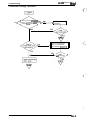
2.3.2 Power On Reset Circuit
When the power supply is turned on, the VL goes up to +9 VDC immediately, but reset IC output
(IC A2,-.Pin 6) is delayed for approximately 80- 1 ma before going up to +9 VDC. The system IC
receives this Lowlevel signal ‘~om the res& IC and resets itself.
VL
+5V
?
t
3ESFT
R37 * \:2)
SYSTEM IC
IC
(ICI)
v(-.~ ~
R38
4
4
GND OUT 6
&
‘ 3 RESET
T
C24
Figure 2-13. Power On Reset Circuit Diagram
2.3.3 Home Position Sensor Circuit
This printer has a connector switch to sense the carriage home position. The system IC receives a
signal (HIGH or LOW) from the HP sensor and remgnize the carriage home position when the
printer is turned on. The comector switch is closed (LOW) when the carriage is in the home
position and is open (HIGH) when the carnage is out of home position.
+5V
SYSTEM IC
(ICI)
R73
SCK
34
I
HP Sensor
R71
Figure 2-14. Home Position Sensor Circuit Diagram
Rev.A
2-13
LX-300 Service Mhnual
Operating Principles
2.3.4 Paper End Sensor Circuit
This printer has a comector switch for sensing the paper end. me system IC receives a signal
(HIGH or LOW) from the connector switch and recognizs a paper end. The comector switch is
closed (LOW) when there is no paper on the platen and is open (HIGH) when paper is present.
+5V
t
SYSTEM IC
(ICI)
R74
PE Sensor
+
PB2
4
R72
J’
Figure 2-15. Paper End Sensor Circuit Diagram
2.3.5 Release Lever Position Sensor Circuit
This printer has a comector switch to detect the type of paper handling. The system IC receives a
HIGH or LOW signal from the comector switch to indicate whether the paper is fed using friction
feed or push tractor feed. Thecomector switch is closed (LOW) when friction feed is selected and
is open ~HIGH) when push tractor feed is selected.
+5V
SYSTEM IC
(lCl)
R53
A NO
58
Release Sensor
R54
J-’
Figure 2-16. Release Lever Position Sensor Circuit Diagram
2-14
Flev.A
.<.;~!$
# , ;;:
LX-300 Sarvica Manual
Operating Pdnoipk
2.3.6 Carriage Motor Driver Circuit
Figure 2-17 shows the carriage motor driver arcuit. The carriage motor driver uses an open-loop,
constant-current drive arrangement. The motor is driven with 2-2 phase excitation and 1-2 phase
excitation.
The ~rriage motor driver
IC (Al) detects the amount of current in the carriage motor coils and
regulates the current. The amount of current flowing in the coils varies, depending on the speed of
the carriage motor. l’he amount of the current is set by the system IC (IC1). Signals are sent to
CRI1 and CR12 on the system IC. The motor driver IC sets the coil current to correspond to the
carriage motor speed. Ports PAO - PA3 on the CPU block control the stepping motor via the gate
array block in IC1.
Table 2-9. Carriage Motor Drive Modes
t
I
I
1
Driver Mode
Excitation Type
Drive Frequency Type
3 x speed
2-2 phase
1080 pps
I 80dpiprinting
1-2 phase
1800 pps
80 dpi printing
1-2 phase
800 pps
180 dpi printing (LQ)
120,90 d~i mintirm
1-2 phase
533pps
1-2 phase
830 ppa
2 x speed
I
I
1 x speed
2/3 x speed
I
7/8 x speed I
Standard Print Character I
(draft)
180,120,90 dpi printing
T
I Home position seek
I
I
+5V+5V
CR MOTOR
DRIVE IC(A1)
tt
R4{ {R5
SYSTEM IC(IC1)
1
1- TDB
‘ 4 INB
1
BF1 OUT ~
BF20UT ‘%
BF1 IN =
BF21N ‘a
OA
MOTOR
ASSY.,CR
1
o-P
CRA
CR-A
CRB
OB 10
o-e
CR-B
VP+
=
+5V
PA3 *
PA2 ~
PA1 ‘la
PAO 141
CRII =
CR12 2
R8
‘1
b
A
‘ 1 1t
,sA~sB
PGA
GB
-
Figure 2-17. Carriage Motor Driver Circuit Diagram
Rev.A
2-15
LX-3(M Service Manual
Operating Principles
2.3.7 Paper Feed Motor Driver Circuit
Figure 2-18 shows the paper feed motor driver circuit, an open-100P, constant-voltage drive with
1-2 phase excitation.
( {“
‘:
The ports (pins 137- 140) on the system IC (ICI) are used to control the stepping motor. The pulse
signal from the IC1 controls four transistors and the stepping motor. l%e motor is driven at five
speeds, 800, 900, 1000, 1200, and 1300 pps, to correspond to the idling voltage and the paper
handling condition. The ICI controls motor speed. At the holding time, The pFCOM voltage is
chang4-VP into VL via A4 by the IC1. “
SYSTEM IC (ICI)
MOTOR ASSY.,PI
(
R84
PFA - ’ 3 7
13s
PFA
Q 1 1
R86
PF~
PFA
Q1
Ra5
Q 1 3
Pm
R87
Q14
Pm
PB- ‘3
PFB
‘“O
nm7
( <<-:
I
*
‘ L
‘1
VP
Figure 2-18. Paper Feed Motor Driver Circuit Diagram
2.3.8 Printhead Driver Circuit
Figure 2-19 shows the printhead driver arcuit block diagram. Print data, already expanded into
image data, is split by the CPU block and transferred to the latch arcuit in the gate array block in
the system IC (ICI). Port AN6 (pin 66) of ICI samples the voltage of the +35 VDC line via the A/D
converter. By sampling the +35 VDC line voltage and dete rmining the length of the head drive
signal, it is possible to maintain the energy supplied to the head at a constant level. If the voltage
from the +35V line is HIGH, ICI shortens the output pulse. If the voltage from the +35 VDC line is
LOW, ICI lengthens the output pulse.
Printhead
SYSTEM IC (ICI)
I
1
‘~
HD1
HD2
HD3
HD4
HDs
HD6
HD7
HDs
HD9
;p~~
At&
68
RIO
D1
F14
- c ?
Rll
~
Figure 2-19. Printhead Driver Circuit Diagram
2-16
Rev.A
Opamting Principk
LX-300 Sanka Manual
2.3.9 Interface Circuit
Figure 2-20 shows the parallel interface circuit block diagram. Data from the host mmputer is
latched within the system IC by a WOOSTROBE signal. The system IC outputs a BUSY signal
automatically to stop the host computer from sending further data. The CPU block reads the data
latched in the gate array block periodically without generating an interrupt.
STSTEM IC
PARALLEL l/F
ICI
y / / / / y / / / / / / / / / ‘ND7-0
“w.
5’ STROBE
......
--h
Figure 2-20. Parallel Interface Block Diagram
Figure 2-21 shows the serial interface circuit block diagram. The serial interface conforms to
EIA-232D. RXD is data received by the serial 1/0 of the CPU block from the host commter via
driver/receiver IC2. Data is trans%tted to an irmut buffer in the svstem IC from the Cl% block.
Printing starts when a CR code is received or whe~ the input but%r & filled.
Driver/Reciver (IC2)
TXD
DTR
RXD
CTS
●
SYSTEM IC (ICI)
365 Pm
PB3
35‘ Pcl
6. ~
I
Figure 2-21. Serial Interface Block Diagram
Rev.A
2-17
LX#Xl Service Manual
Operating Principles
2.3.10 EEPROM Control Circuit
Figure 2-22 shows the EEPROM control arcuit block diagram. ‘The EEPROM (A5) contains such
information as the top-of-form position. The EEPROM is non-volatile memory, so information is
not lost if the printer is powered off. Since the EEPROM is a serial I/O-type device, the CPU
(:“-%
converts 8-bit data into serial data.
+5V
4
SYSTEM IC (ICI)
PB7
PB5
PBO
PB1
-+-h
9
7
2
3
ICT1
EEPROM (A5)
1
Cs
CK
3
DI
4
Do
2
J
Figure 2-22. EEPROM Control Circuit Diagram
2.3.11 CS Motor Assembly Circuit
Figure 2-23 shows a block diagram of the CS motor assembly arcuit in the optioml color upgrade
kit. The CS motor assembly is a pe rmanent ma~et (PM) stepping motor, driven with 2-2 phase
excitation in proportion to the desired mtatioti speed. W motor GUI be rotated in either
direction and stopped at any position. Four phase signals are directly output from the system IC
and pass through a transistor array. The drive voltage is constant (i.e., +35 VDC from the VP line).
35 VDc * 10 Yo
245 mA ( peak)
Source Voltage
Current Con~ump60n
SYSTEM IC (ICI)
a
MOTOR ASSY.,CS
F
Q1
PA7 14s
R20
147
R21
I
CS_A
14a
R22
I
CS B
14s
R23
I
(XA
PA6
PA5
PA4
+5V
PB6
Printer
t
CS-B
,...m
f,,;.
*I
N
I +35V
I
Color Upgrade Kit
Figure 2-23. CS Motor Assembly Circuit Diagram
2-18
Rev.A
operating Ptincipk3
LX-300 Sarvica Manual
2.3.12 Color Ribbon Sensor Circuit
The printer’s color ribbon arcuitry in shown in the figure below. The CPU receives signals (HIGH
or LOW) from the mechanical switch. lle signal is HIGH when a color ribbon is installed and is
LOW otherwise.
+5V
Sensor
AN4 ~
A
i
i
i
L
i
I
Printer
I
Color Upgrade Kit
Figure 2-24. Color Ribbon Sensor Circuit Diagram
Rev.A
2-19
(
CHAPTER 3 Disassembly and Assembly
Table of Contents
3.1 OVERVIEW
3.1.1 Disassembly Precautions . . . . . . . . . . . . . . . . . . . . . . . . . . . . . . . . . . . .
3.1.2 TOOk3 . . . . . . . . . . . . . . . . . . . . . . . . . . . . . . . . . . . . . . . . . ........0-.
3.1.3 Service ChecksAfterRepair . . . . . . . . . . . . . . . . . . . . . . . . . . . . . . . . . .
3.1.4 Specifications forScrews. . . . . . . . . . . . . . . . . . . . . . . . . . . . . . . . . . . . .
3-1
3-1
3-1
3-2
3-3
3-4
3.2 DISASSEMBLY AND ASSEMBLY
3.2.1 Removing the Printhead . . . . . . . . . . . . . . . . . . . . . . . . . . . . . . . . . . . . . 3-5
3.2.2 Removing the HOUSING ASSY.,UPPER . . . . . . . . . . . . . . . . . . . . . . . . 3-6
3.2.2.1 Removing the ROLLER ASSY.,EJECT. . . . . . . . . . . . . . . . . . . . 3-6
3.2.3 Removing the BOARD ASSY.,MAIN and PSB/PSE . . . . . . . . . . . . . . . . 3-7
3.2.3.1 Removing the BOARD ASSY.,MAIN. . . . . . . . . . . . . . . . . . . . . . 3-8
3.2.3.2 Removing the BOARD ASSY.,PSB/PSE . . . . . . . . . . . . . . . . . . 3-8
3.2.4 Removing the Printer Mechanism . . . . . . . . . . . . . . . . . . . . . . . . . . . . . . 3-9
3.2.4.1 Removing the MOTOR ASSY.,PF . . . . . . . . . . . . . . . . . . . . . . 3-10
3.2.4.2 Removing the MOTOR ASSY.,CR . . . . . . . . . . . . . . . . . . . . . . 3-11
3.2.4.3 Removing the PLATEN. . . . . . . . . . . . . . . . . . . . . . . . . . . . . . . 3-12
3.2.4.4 Removing the DETECTOR,PE. . . . . . . . . . . . . . . . . . . . . . . . . 3-13
3.2.4.5 Removing the DETECTOR, HP. . . . . . . . . . . . . . . . . . . . . . . . . 3-14
3.2.4.6 Removing the Release Lever Position Sensor . . . . . . . . . . . . . 3-14
3.2.4.7 Removing the CARRIAGE ASSY.. . . . . . . . . . . . . . . . . . . . . . . 3-15
3.2.4.8 Removing the Ribbon Drive Gear Assembly. . . . . . . . . . . . . . . 3-16
3.2.4.9 Removing the PF Gear Assembly. . . . . . . . . . . . . . . . . . . . . . . 3-16
3.2.5 Removing the BOARD ASSY.,INTERFACE . . . . . . . . . . . . . . . . . . . . . 3-17
3.2.6 Removing the ROLLER ASSY.,DRIVEN. . . . . . . . . . . . . . . . . . . . . . . . 3-18
3.2.7 Disassembling and Assembling the Optional Color Upgrade Kit. . . . . . 3-19
3.2.7.1 Removing the MOTOR ASSY.,CS . . . . . . . . . . . . . . . . . . . . . . 3-19
3.2.7.2 Removing the GEAR, CAM,CS . . . . . . . . . . . . . . . . . . . . . . . . . 3-19
3.2.7.3 Removing the Color Ribbon Sensor . . . . . . . . . . . . . . . . . . . . . 3-19
List of Figures
Figure 3-1. Procedure for Disassembling the Printer. . . . . . . . . . . . . . . . . . . . . 3-4
Figure 3-2. Removing the Printhead. . . . . . . . . . . . . . . . . . . . . . . . . . . . . . . . . . 3-5
Figure 3-3. Removing the HOUSING ASSY.,UPPER . . . . . . . . . . . . . . . . . . . . 3-6
Figure 3-4. Removing the ROLLER ASSY.,EJECT. . . . . . . . . . . . . . . . . . . . . . 3-6
Figure 3-5. Removing the SHIELD PLATE. . . . . . . . . . . . . . . . . . . . . . . . . . . . . 3-7
Figure 3-6. Removin~ the BOARD ASSY.,MAIN and PSB/PSE . ...........3-8
Figure 3-7. Bendingthe LED Lead Wires . . . . . . . . . . . . . . . . . . . . . . . . . . . . . . 3-8
Figure 3-8. Removing the Printer Mechanism . . . . . . . . . . . . . . . . . . . . . . . . . . 3-9
Figure 3-9. Removing the MOTOR ASSY.,PF. . . . . . . . . . . . . . . . . . . . . .. ..3-10
Figure 3-10. Removing the MOTOR ASSY.,CR. . . . . . . . . . . . . . . . . . . . . .. .3-11
Figure 3-11. Removing the PLATEN . . . . . . . . . . . . . . . . . . . . . . . . . . . .....3-12
Figure 3-12. Removing the DETECTOR,PE . . . . . . . . . . . . . . . . . . . . . .....3-13
Figure 3-13. Wiring of the PE Sensor. . . . . . . . . . . . . . . . . . . . . . . . . . . . . . . . 3-13
Figure 3-14. Removing the DETECTOR,HP . . . . . . . . . . . . . . . . . . . . . .....3-14
Figure 3-15 Removing the Release Lever Position Sensor. . . . . . . . . . . . . . . 3-14
Figure 3-16 Removing the CARRIAGE ASSY. . . . . . . . . . . . . . . . . . . . . .. ..3-15
Figure 3-17 Removing the Ribbon Drive Gear Assembly . . . . . . . . . . . . . . . . 3-16
Figure 3-18 Removing the BOARD ASSY.,INTERFACE . . . . . . . . . . . .....3-17
Figure 3-19 Removing the ROLLER ASSY.,DRIVEN . . . . . . . . . . . . . . .....3-18
Figure 3-20 Disassembling the Optional Color Upgrade Kit . . . . . . . . . .....3-19
~
List of Tables
Table 3-1. Recommended Tools . . . . . . . . . . . . . . . . . . . . . ...............3-1
Table 3-2. Equipment Required for Maintenance. . . . . . . . . . . . . . . . . . . . . .. .3-1
Table 3-3. Inspection Checklist for Repaired Printer . . . . . . . . . . . . . . . . . . . . . 3-2
Table 3-4. Screw Abbreviations. . . . . . . . . . . . . . . . . . . . . . . . . . . . . . . . . . . . . 3-3
c“
.7...
,!
..... .
Disasaambly and Asaambly
L.XWO Service Manual
3.1 OVERVIEW
This section describes various points to note when disassembkg and assembling the printer.
3.1.1 Disassembly Precautions
Follow the precautions below when disassembling the printer.
I
Before disassemblin~ assemblin~ or adjusting the printer, disconnect the power supply
cablefiom the AC power socket. Failure to do can cause personal injuy.
I
To maintain efficient printer operation:
● Use only the recommended tools for maintenance work.
● Use only the recommended lubricants and adhesives (see Chapter 6).
● Adjust the printer only in the manner desm”bed in this manual.
3.1.2 TOOiS
Tables 3-1 and 3-2 list the tools recommended for disassembling assembling or adjusting the
printer. Use only tools that meet these specifications.
Table 3-1. Recommended Tools
Tool
Part No.
Round-nose pliers
B740400100
I Nippers
I B7405OO1OO
Tweezers
B741OOO1OO
Soldering iron
B7402OO1OO
I E-rhw holder#2.5
I
Phillips screwdriver No.2
B743800200
Normal screwdriver
B743000100
—
Thickness gauge
Note:
B740SO0400
All tools are commemially available.
Table 3-2. Equipment Required for Maintel mce
e
i
Description
I
Spaoif*ion
Multimeter
Oecillosoope
Note:
Rev.A
50 MHz
An oscilloscope is required om’y forsendcers who repair to the G vponent level.
3-1
LXXX) Service Jl&mual
Disassembly and Assembly
3.1.3 Service Checks After Repair
Before returning the printer after service,
make servicing and shipping more effiaent.
use the checklist in Table 3-3, Whib
provides a record to
Table 3-3. Inspection Checklist for Repaired Printer
Category
Item to Check
Component
Are any wires broken?
Printhead
Are any
wires worn out?
Is Check Required?
❑ Chsck@ ❑ Not necessq
❑ Checkedn Not necessary
Does the carriage move smoothly?
~amage
mwhanism
❑ Not necessary
❑ Movement noisyn Mechanism dirty
❑ Mechanism oily
D Checked
Is the CR motor assembly at the
correct temperature (not overheating)
❑ Checkeda
Not necessary
Is paper advancing smooth~
❑ Movement noiayu Mechanism dirty
❑ Mechanism oily
Printer
units
Paper
advance
mechanism IS the Pper adVSTICe motor running
at the correct temperature (not
overheating)
❑ Checked ❑ Not necessary
Is the tractor feeding the paper
~rr-lw
Is the paper path cfear of all
obstructions?
❑ Checked ❑ Not necessary
Is the platen free of damage?
❑ Chackad ❑ Not necessary
Ribbon
mask
IS the ritin mask free of distortion?
❑ Checkedn Not necessary
Self-print
test
Was the self~rint successful?
❑ Checked D Not neceasaty
Printhead
printing
Defautt
setting
ROM
version
3-2
Shipment
❑ Chackedn
i,-.
Not necessary
Is the platen gap adjusted correctly?
❑ Checked ❑ Not necessary
H Checked ❑ Not necessary
IS the bidirectional print position
adjusted corractfy?
❑ Checkedn Not necessary
Have user changeable settings been
reset to the default value?
❑ Checked ❑ Not necessary
ROM version
❑ Checkecf ❑ Not necessary
Has the ribbon been removed?
❑ Checked ❑ Not necessary
Have all relevant parts been included
in the shipment?
❑ Chalked ❑ Not necessa~
On-line test Was the on-line test suocessfui9
System
upgrade
❑ Checked ❑ Not n=essa~
Is the type of paper in the printer
feeding smoothl~
Paper path
Adjustment
D Checked H Not necessary
Rev.A
r:,.
Disassembly and Assembly
LX-300 Service Manual
3.1.4 Specifications for Screws
Table 3-4 lists the abbreviations used in the
following sections for small parts, such as screws and
washers.
Table 3-4. Screw Abbreviations
Abbreviation
t
I
CPB
Cross-recessed pan head B-tight screw
CBB
Cross-recessed bind head B-tight screw
CBS
Cross-recessed bind head S-tight screw
CBC
Cross-recessed bind head C-Lamitite screw
CTB
Cross-recessd bind head tapping screw
CB(0)
Cross-recessed bind head with outside toothed lock washer
CTBP
Cross-recessed bind head tapping screw with fiat washer
CF
Rev.A
Part Name
Cross-recessed countersunk screw
3-3
LX-300 Service Manual
Disassembly and Assembly
3.2 DISASSEMBLY AND ASSEMBLY
This section descnibes the procedures for disassembling and assembling the main components of
the printer. When the procedure for installing a component is Simply tie reverse of the procedure
for removing the component, no description of the installation is given. Arty points of special
concern follow the description of the procedure.
●
‘
●
Before disassembling any part of the printer, note the warnings in Section 3.1.
Before disassembling any part of the printer, remove the paper and the ink n“bbon.
Disassembly includes the following seven procedures:
Removing the printhead
Removing the HOUSING ASSY.,UPPER
Removing the BOARD ASSY.,MAIN and PSB/PSE
Removing the Printer Mechanism
Removing the BOARD ASSY.,INTERFACE
Disassembling the ROLLER ASSY.,DRIVEN
Disassembling the Optional Color Upgrade Kit
1.
2.
3.
4.
5.
6.
7.
Refer to the diagrams in the appendix to see how components fit together.
I
I
sTART
{
I
Unplug the power cable and the
interface cable from the printer!
Page
Section
Description
I
Removing the Prlnthead
I
Removing the ROLLER ASSY., DRIVEN
I
3.2.2.1
I 3-6
Removing the HO USING ASSY.. U PPER
I1
Removing the ROLLER ASSY., EJECT
1
I 3-7,8
3.2.3
Removing the BOARD ASSY., MAIN and PSB I PSE
I
1
Fiiiz
Removing the
,
I3-10
3.2.4.1
Removing the MOTOR AS SY., PF
1
3.2.4.3
I 3-12
Removing the PLATEN
H
II
3.2.4.2
13-11
Removing the MOTOR ASSY., CR
..:%
I
1
3.2.4.4
f’. -..,-. ‘
I 3-13
Removina the DETECTOR ASSY.. PE
I
3.2.4.5
Removina the Release Lever Position Sensor
3.2.4.8
3.2.4.7
Removing the CARRIAGE ASSY.
I 3-16
Uemovina the P F Gear Assv.
3.2.4.9
3.2.5
Remov8ng the
Removing the Ribbon Drive Gear Assy.
I
I 3-17
BOARD ASS Y., INTE RFACE
i
Figure 3-1. Procedure for Disassembling the Printer
.:
,.
3-4
Rev.A
Disassamb& and Assembly
LX-3W Sanka Manual
3.2.1 Removing the Printhead
Remove the COVER ASSY.,PRINTER, EDGE GUIDE ASSY., ribbon cartridge, TRACTOR
ASSY., PLATEN KNOB, and optional color upgrade kit.
2. Remove the CPB (M3 x 14) screw attaching the printhead.
3. Remove the printhead.
4. Remove the flexible flat cable (lWC) from the printhead.
1.
Figure 3-2. Removing the Printhead
Rev.A
3-5
LX-300 Service Manual
Disassembly and Assembly
3.2.2 Removing the HOUSING ASSY.,UPPER
1.
Remove the COVER ASSY.,pM~R, EDGE GUIDE AssY., ribbon c=tidge, TRACI’OR
ASSY., PLATEN KNOB, and optional color upgrade kit.
2. Remove the 4 CPB (M4 x 14) screws attaching the HOUSING ASSY.,UPPER to the
HOUSING,LOWER.
3. Liftoff the HOUSING ASSY.,UPPER.
CPB(M4X14)
~’~
HOUSING ASSY ., UPPER
ING,LOWER
Figure 3-3. Removing the HOUSING ASSY.,UPPER
3.2.2.1 Removing the ROLLER ASSY.,EJECT
1. Remove the HOUSING ASSY.,UPPER. ( see Section 3.2.2.1).
2. Lift the ROLLER ASSY.,EJE~up and atananglefrom the HOUSING ASSY.,UPPER.
When removing the ROLLER ASSY.,EJECT, the SPRING,5U0 may pop out.
Note:
,,.-4. %
f
,,,
.., . . . . .
ASSY.,UPPER
R ASSY.,EJECT
\
Figure 3-4. Removing the ROLLER ASSY.,EJECT
3-6
Rev.A
DisassembiyandAssembly
LX-31M Service Manual
3.2.3 Removing the BOARD ASSY.,MAIN and PSB/PSE
1.
Remove the COVER ASSY.,PRINTER, EDGE GUIDE ASSY., ribbon cartridge, TIUU30R
ASSY., PLATEN KNOB, and optional color upgrade kit.
2. Remove the HOUSING ASSY.,UPPER (see Section 3.2.2).
3. Discomect the 3 flexible flat cables (FFCS) and 6 connectors from the BOARD ASSY.,MAIN
and PSB/PSE.
4. Remove the 4 CBB (M3 x 8) screws attaching the shield plate to the main board assembly and
PSB/PSE, the CBB (M3 x 8) screw attaching the CS BOARD and the CBC (M4 x 8) screw
attaching the ground wire of the POWER CABLE.
5. Disengage the SHIELD PLATE and BOARD ASSY.,MAIN and PSB/PSE from the
GROUNDING PLATE.
(
e
CBB(
LE
GROUNDING PLATE
Figure 3-5. Removing the SHIELD PLATE
Rev.A
3-7
LX&Xl Service M%ual
Disassembly and Assembly
3.2.3.1 Removing the BOARD ASSY.,MAIN
Remove the FFC of the BOARD ASSY.,PSB/I’SE from comector CN2 of the BOARD
ASSY.,MAIN.
2. Remove the CBC (M3 x8) screw and the3 CB USCAC (M3 x 8)
3. Remove the BOARD ASSY.,MAIN.
1.
fl::y
%. . .
3.2.3.2 Removing the BOARD ASSY.,PSBIPSE
Remove the FFC for the BOARD ASSY.,PSB/I’SE from comector CN2 on the BOARD
ASSY.,MAIN.
2. Remove the CB USCA C(M3 x 10) screw and 2 CB USCA C(M3 x 8) ssrews.
3. Remove the BOARD ASSY.,PSB/PSE.
1.
When replacing the BOARD ASSY.,MA.IM bend the LED lead wires parallel to the
BOARD ASSY.J4AIN (see Figure 3-7).
. The SHIELD PLATE is easily bent; be carefil when tightening the screws that attach it to
the BOARD ASS Y.,MAIN and PSBIPSE.
●
‘=.
----
CB USCA C(M3X8)
CB USCA C(M3X1O)
L
A
CB USCA C(M3X8)
,CBC(M3X8)
k
/
tiOO\MdXU)
BOARD ASSY.,MAIN
‘v
Figure 3-6. Removing the BOARD ASSY.,MAIN and PSB/PSE
BOARD ASSY.,MAIN
\
Figure 3-7. Bending the LED Lead Wires
3-8
Rev.A
DisassembiyandAssamblY
LX- Service Manual
3.2.4 Removing the Printer Mechanism
1.
Remove the COVER ASSY.,PRINTER, EDGE GUIDE ASSY., ribbon cartridge, TRACT’OR
AS5Y., PLATEN KNOB, and optioml color upgrade kit.
2. Remove the HOUSING ASSY.,UPPER (see Section 3.2.2).
3. Remove the connectors and FFCS from the BOARD ASSY.,MAIN.
4. Remove the3 SHAFT,HOUSING,LOWER (1018296).
5. Remove the SHAFT,HOUSING,LOWER (1015457). Note that this shaft is different from the
three described in the previous step.
6 Remove the printer mechanism.
SHAIT,HOUSING,
ff~-J-w
LOWER (1015457) s
LOWER(1018296)
‘zq
f’h
m?
Printer Mechanism
Figure 3-8. Removing the Printer Mechanism
Rev.A
3-9
LX-3.X) Service Manual
Disassembly and Assembly
3.2.4.1 Removing the MOTOR ASSY.,PF
1. Remove the printer mechanism (see Section 3.2.4).
2. Remove the GROUNDING SPRING,PLATEN that secures the platen shaft. (see Section 3.2.43)
3. Remove the CBB (M3 x 8) screw attaching the MOTOR ASSY.,PF to the FRAME,LIGHT.
4. Release the clip holding the MOTOR ASSY.,PF from the FRAME,RIGHT.
5. Remove the MOTOR ASSY.,PF from the FRAME,RIGHT.
.
‘.:-
FRAME, RIGHT TR~NSMISSloN
GEAR
\uJy~
/
P
CBB(M3X8)
&
MOTOR, ASSY.,PF
Figure 3-9. Removing the MOTOR ASSY.,PF
3-1o
Rev.A
Disasaambly and Assambly
LX-31M Service Manual
3.2.4.2 Removing the MOTOR ASSY.,CR
(~,
1. Remove the Printer Mechanism (see Section 3.2.4).
2. Remove the BELT TENSION SPRING from the hook on the MOTOR ASSY.,CR and the hook
on the FRAME, BASE.
3. Remove the TIMING BELT from the PULLEY DRIVE.
4. Remove the E-ring, PULLEY WASHER, BELT PULLEY FLANGE, and PULLEY DRIVE from
the MOTOR ASSY.,CR.
5. Rotate the MOTOR ASSY.,CR counterclockwise and remove it.
TIMIN~ BELT
I
i
.E-ring
PULLEY WASHER
Q& BELT PULLEY FLANGE
:
/
BELT TENSION SPRING
MOTOR ASSY.,CR
\
FRAME, RIGHT
Figure 3-10. Removing the MOTOR ASSY.,CR
Rev.A
3-11
LX-WI Service Manual
Disassembly and Assembly
3.2.4.3 Removing the PUiTEN
.fl \
i-x :,
1. Remove the printer mechanism (see Section 3.2.4).
2. Remove the GROUNDING SPRING,PLATEN that secures the platen shaft.
3. Remove the GEAR,25 from the FRAME,RIGHT.
4. Disengage the teeth of the 2 BUSHING 11s and rotate them.
5. Rotate the PLATEN and remove it.
w,
BuSHING,l 1
.
.
PLATEN
\,
\,
\
~
“x
.....
GROUNDING SPRING,
Figure 3-11. Removing the PWTEN
3-12
Rev.A
Disassembly and Assambly
LX-300 Service Manual
3.2.4.4 Removing the DETECTOR,PE
1. Remove the printer mechanism (see Section 3.2.4).
2. Remove the PLATEN (see Section 3.2.4.3).
3. Release the SHAFT FRICTION of the PAPER GUIDE,UPPER from the clips on the
FRAME,RIGHT and LEFT.
4. Remove the PAPER GUIDE,UPPER from the FRAME,RIGHT and LEIT.
c
s
ON
GHT
Figure 3-12. Removing the DETECTOR,PE
5. Release the 2 clips securing the DETECTOR,PE and remove it.
DETECTOR, PE
ire of DETECTOR,PE
\ PAPER GUI DE, UPPER
Figure 3-13. Wiring of the PE Sensor
Rev.A
3-13
LX-3(IQ Service Manual
Disassembly and Assembly
3.2.4.5 Removing the DETECTOR,HP
1. Remove the printer mechanism (see Section 3.2.4).
2. Release the 2 clips attaching the DETECTOR,HI’ and remove it. The clips can be accessed
through 2 holes in the FRAME,BASE; to release the clips, push each with a pair of tweezers.
Figure 3-14. Removing the DETECTOR,HP
3.2.4.6 Removing the Release Lever Position Sensor
1. Remove the MOTOR ASSY.lF(See Wion3.2.4.1).
2. Release the 2 clips that attach the release lever position sensor to the frame of the MOTOR
ASSY.,PF.
3. Remove the release lever position sensor from the frame of the MOTOR ASSY.,PF.
Frame of the
Release Lever
MOTOR ASSY.,PF position Sensor
., . ... .
: . , “,’”
f
Clip
Figure 3-15. Removing the Release Lever Position Sensor
3-14
Rev.A
Disassembly and Assembly
LX300 Service Manual
3.2.4.7 Removing the CARRIAGE ASSY.
Remove the printer mechanism (see Section 3.2.4).
Remove the BELT TENSION SPRING from the hook on the MOTOR ASSY.,CR (see Section
3.2.4.2), and remove the TIMING BELT of the CARRIAGE ASSY. from the PULLEY DRIVE.
3. Release the hook that attaches the SHEET,CABLE,HEAD to the FRAME,BASE. Slide the cable
to the left and remove it.
4. Remove the printhead FFC from the FRAME,BASE.
5. Remove the GROUNDING PLATESH~,CR from the left side of the printer mechanism.
6. Rotate both sides of the BUSH,PARALLEL ADJUST and remove them from the FRAME,LEFT
and RIGHT.
7. Remove the SHAFT ASSY.,CR GUIDE and the CARRIAGE ASSY.
1.
2.
$(=
LEVER,G,ADJUST
p
\,
GROUNDING
PLATE,SHAH,CR
\
RALLEL ADJUST
BUSH, PARALLEL
ADJUST
SHE~,CABLE,HEAD
FRAME,BASE
FRAME, RIGHT
\’-Ql
~
CABLE HEAD
Figure 3-16. Removing the CARRIAGE ASSY.
Rev.A
3-15
Disassembly and Assembly
LX-3tM Service Mhnual
3.2.4.8 Removing the Ribbon Drive Gear Assembly
1. Remove the printer mechanism (see Section 3.2.4).
2. Release the3 hooks attaching the COVER,RD to the FRAME,LEFI’.
3. Remove the COVER,RD.
4. Remove the BELT TENSION SPRING between the hook on tie MOTOR ASSY.,CR and the
hook on the FRAME,BASE (see Section 3.2.4.2).
5. Remove the TIMING BELT from the PLJLLEY DRIVEN.
A!.,+,
,,
i
,.
RATCHET,RD
cov&&~g;,:,H,,ANGE
$-
R18BON P~N=AR’f
GEAR SHAH
G E A R ,5.1 ,16.2
1,
‘? ji.wLs~~~~~~~E~R’”’”
PLANE WASHER
SPRING WAStiER
\
GEAR,14.4
0;
,
FRAME,BA=
,
\
\
GEAR,13.2
kQ
6
,16.2
\
Figure 3-17. Removing the Ribbon Drive Gear Assembly
Make sure not to put the ZZMING BELT between the COVERJU3 and the FRAME,LEFT.
3.2.4.9 Removing the PF Gear Assembly
Remove the MOTOR ASSY.,PF (see Section 3.2.4.1).
2. Remove the PF gear train and the release lever.
1.
3-16
Rev.A
, -. ,.
i
$-
LX-300 Samica Manual
DiaassemblyandAssembly
3.2.5 Removing the BOARD ASSY.,INTERFACE
1. Remove the printer mechanism (see Section 3.2.4).
2. Remove the GROUNDING PLATE connecting the SHIELD PLATE,I NIERFACE and the
SHIELD PLATE.
3. Remove the CBB (M3 x8) screw and the CBT(M3 x 10) screw attaching the COVER,BO’IIOM
to the HOUSING,LOWER.
4. Remove the 2 CBB (h43 x 8) screws attaching the BOARD ASSY.,1 NTERFACE to the
HOUSING,LOWER.
5. Remove the COVER,BOTTOMand the BOARD ASSY.,INTERFACE.
BOARD ASSY.,INTERFACE
GROUNDING PLATE I
IWATE,,NTERFACE
HOUSING, LOWER
Figure 3-18. Removing the BOARD ASSY.,INTERFACE
Rev.A
3-17
LXi300 Service M5nual
Disassembly and Assembly
3.2.6 Removing the ROLLER ASSY.,DRIVEN
1. Remove the COVER,PRINTER.
2. Remove the CF (M2.6 x 8) screw attaching the ROLLER ASSY.,DRTVEN.
3. Remove the ROLLER ASSY.,DRIVEN.
CF(M2.6X8)
ROLLER, DRIVEN
I SPRING,73
.h
7°
/
A
/
&
0
“’ i,’
!’
“T.e
W~DE;R,ROLLER,
COVER, ROLLER, DRIVEN
COVER, PRINTER
\v
Figure 3-19. Removing the ROLLER ASSY.,DRIVEN
3-18
Rev.A
“
Dkassembly and Assembly
LX-WI Service Manual
3.2.7 Disassembling and Assembling the Optional Color Upgrade Kit
3.2.7.1 Removing the MOTOR ASSY.,CS
1. Remove the CBB (M3 x 8) screw attaching the MO~R ASSY.,CS to the COVER,CS.
2. Release the 2 clips attached to the COVER,CS.
3. Remove the MOTOR ASSY.,CSwith the BOARD ASSY.,CS from the COVER,CS.
3.2.7.2 Remove the GEAR,CAM,CS
1. Remove the MOTOR ASSY.,CS (see Section 3.2.7.1).
2. Remove the E-ring3 from thecolorcam shaft.
3. Remove the GEAR,CAM,CS.
3.2.7.3 Removing the Color Ribbon Sensor
1. Remove the MOTOR ASSY.,=and the BOARD ASSY.,CS(see Section3.2.7.1).
2. Remove the E-ring4 from the cartridge holder shaft.
3. Remove the HOLDER,CARTRIDGE,COLOR from the M~R ASSY.,CS.
4. Release the clip that attaches the HOLER,CARTRIDGE,COLOR to the color ribbon sensor.
5. Remove the color ribbon sensor comector from the BOARD ASSY.,CS.
COVER,CS
BOARD ASSY..CS
HOLDER,CARTRIDGE, COLOR
Figure 3-20. Disassembling the Optional Color Upgrade Kit
f?ev.A
3-19
CHAPTER 4 Adjustments
Table of Contents
4-1
4.1 ADJUSTING THE PRINTER MECHANISM
4.1.1 Platen Gap Adjustment . . . . . . . . . . . . . . . . . . . . . . . . . . . . . . . . . . . . . . 4-1
4.2 DEFAULTS, MACHINE INFORMATION S~lNGS, AND
4-2
BIDIRECTIONAL ADJUSTMENT
4.2.1 Default Settings. . . . . . . . . . . . . . . . . . . . . . . . . . . . . . . . . . . . . . . . . . . . 4-2
4.2.2 Bidirectional Adjustment . . . . . . . . . . . . . . . . . . . . . . . . . . . . . . . . . . . . . 4-4
List of Figures
Figure 4-1. The Flowchart of the Platen Gap Adjustment . . . . . . . . . . . . . . . . . 4-1
Figure 4-2. The Bidirectional Pattern Print. . . . . . . . . . . . . . . . . . . . . . . . . . . . . 4-4
Adjuatmenta
LX-3U0 Service Manual
4.1 ADJUSTING THE PRINTER MECHANISM
This section describes the adjustments you may need to make to the printer mechanism.
4.1.1 Platen Gap Adjustment
If you have rotated or reassembled the CR guide shaft assembly or the parallelism adjustment
bushina or if printing is abnormal, you must adjust the platen and the printhead.
1.
2.
3.
4.
5.
6.
7.
Set the release lever to the friction position.
Remove the upper housing assembly (see Section 3.2.1).
Set the gap adjustment lever to O.
Remove the printhead.
Remove the ribbon mask with a pair of tweezers.
Install the printhead.
Adjust the platen gap using the flowchart below. The correct platen gap is 0.455 mm *
0.015 mm. When measuring the gap, take care to let the gauge fall between the platen and the
printhead by gravity only. To increase the platen gap, turn the parallelism adjustment bushing
toward the platen using a screwdriver. To reduce the platen gap, turn the parallelism
adjustment bushing away from the platen.
Adjust the Platen
Adjust the Platen
Figure 4-1. The Flowchart of the Platen Gap Adjustment
Rev.A
4-1
LX-300 Service Mimuai
Adjustments
4.2 DEFAULTS, MACHINE INFORMATION SEITINGS, AND
BIDIRECTIONAL ADJUSTMENT
4.2.1 Defaults and Machine Information Settings
Perform the
1.
2.
3.
4.
5.
6.
7.
procedure below when the main board assembly is replaced.
Comect the printer to a PC.
Turn the printer on.
Load paper into the printer by pressing the LF/FF button. You can use either cutsheet or
continuous paper.
Load the GWBASIC program onto the PC.
Insert a diskette containing the LX-300 Adjustment Program into the PC’s diskette drive.
Load the LX-300 Adjustment Program named “LX300.”
When you run the program, the following message appears on the display:
LX-300 Adjustment Program
1. Bi-D Adjustment
2. Defaults& Machine Information Settings
3. END
If ready, press 1-3 and the Enter key. –
( “$ ‘“
L
8. Press 2, then Enter to select D#aults &Machine In@matwn Settings.
9. The following message appears on the display:
Which destination do you want to select?
EAI : 1 EDG : 2EIS :3 EFS : 4 EHK :5
ESP : 6 ESP : 7 EUL : 8 EIB :9 EAL : A
ETT : B
Press 1- B and the Enter key.
10. The following message appears on the display:
LX-300
Default & Machine Information Data
Registration Program
# ““,.
*,
.-.
.., .,
If you press the Y key, all data stored in the EEPROM on the
main board will be initialized to the factory default settings.
Before proceedin& confirm the following
1. The printer is comected to the computer correctly.
2. The printer is on.
3. Paper is loaded in the printer.
If ready, press Y and the Enter key. –
4-2
F?ev.A
Adjustments
LX41M Sarvka Manual
11. Press Y, then Enter. The default setting table appears on the display:
Add Function
No.
SW& Valid
1
Message language
English
2
Tractor control
Single
3
Character table
PC-437
4
Page length
11 inch
5
1 inch skip over perforation
OFF
6
Intetface selection
OFF
7
Bit rate
9600 bps
8
Prii bit
NONE
9
Date Length
10
ETWACK protocol
11
Auto tear off
OFF
12
Character spacing
10 cpi
13
Auto line feed
OFF
14
Shape of zero
Not slashed
7 bit
DISABLE
I%ese are the factory defaults programmed into this printer.
12. Press Y, then Enter to confirm these settings and return to the initial menu.
13. Exit the program by pressing3, then Enter.
14. The following message appears on the display:
Any setting value specified within this program
is not stored in the EEPROM until you turn the printer OFF.
Turn the printer OFF now.
15. Turn the printer off to store the defaults shown above into the EEPROM on the main board
assembly.
Note:
If you have replaced the m“n board assembly, you must also perform the bidirectional
adjustment procedure after completing this procedure.
44
Rev.A
!
LX&M Service Mhnua/
Adjustments
4.2.2 Bidirectional Adjustment
This section describes the adjustment prmedure n=ssary when the LX-3W printer is reassembled
or when parts are reinstalled or replaced. T’his pr~ure is also n=es=q if the main board
assembly has been replaced.
Notes:
. When the main board is replaced, perform the Defaults& Machine Information Settings
procedure first, then petiorm the Bi-D Adjustment prucedure.
●
Theprintercovermustbe installed when youperfonn the Bi-Dadjustment.
. Do notperfonn the Bi-D Adjustment procedure if the input voltage is fluctuating heavily.
. T4e optional color upgrade kitmustbe removed when youperfonn the Bi-D a~”ustment.
1.
Comect the printer to a PC.
2. Turn the printer on.
3. Load paper into the printer by pressing the LWFF button.
4. Load the GWBASIC program onto the PC.
5. Insert a diskette containing the LX-300 Adjustment Program into the PC’s diskette drive.
6. Load the LX-300 Adjustment Program.
7. When you run the program, the following message appears on the display:
(...
LX-3(MI Adjustment Program
1. Bi-D Adjustment
2. Defaults& Machine Mxmation Settings
3. END
If ready, press 1-3 and the Enter key. -
.
if’ll:iill D El El H II II El II II H El H H II
im’il II El El H El It El 1! 1! H H El El II
ih:lh II H II H II El El H H II El II El II
illl:h El El H El H H El u El II u El El El
Figure 4-2. The Bidirectional Pattern Print
44
Rev.A
!
LX&M Service Manual
8.
9.
Adjustments
Type 1 to select Bi-D Adjustment then press Enter. After 10 line feeds, the printer prints 5 rows
of H characters in both draft and LQ modes. When the printer begins bidirectional printin&
the message “Bi-D TEST PRINTING” appears on the display.
After printing is complete, the following message appears on the display:
Bi-D INPUT
Draft: -
From the 5 rows of draft patterns, find the row in which the vertical lines in the H are best
aligned, then enter the value assigned to that row. The following figure is an example of the
Bi-D printout.
After
you enter the value for draft, the following message appears on the display:
10.
LQ : From the 5 rows of LQ patterns, find the row in which the vertical lines in the H are best
aligned, then enter the value assigned to that row.
11. The printer lets you check your print pattern selection for confirmation following steps 9 and
10 by printing one row of the pattern you selected.
12. After the printer prints check patterns for confirmation, the followin g message appears on the
display:
If Bi-D is correct, press “Y’ and the Enter key, and
if Bi-D is incorrect, press “N” and Enter. –
13. If your printed pattern is aligned vertically, press Y and Enter to complete the Bi-D
adjustment. Otherwise, press N to return to step 9 to specify another adjustment value.
Rev.A
4-5
Chapter 5 Troubleshooting
Table of Contents
5.1 OVERVIEW
5-1
5.2 UNIT LEVEL TROUBLESHOOTING
5-4
5.3 REPAIRING THE MAIN BOARD ASSEMBLY
5-11
5.4 REPAIRING THE PRINTER MECHANISM
5-13
List of Figures
Figure 5-1. Troubleshooting Procedure. . . . . . . . . . . . . . . . . . . . . . . . . . . . . . . 5-1
Figure 5-2. Printhead Connector Pin Alignment . . . . . . . . . . . . . . . . . . . . . . . . 5-2
Figure 5-3. Flowchart Symbols . . . . . . . . . . . . . . . . . . . . . . . . . . . . . . . . . . . . . 5-4
List of Tables
Table 5-1. Printhead Coil Resistance . . . . . . . . . . . . . . . . . . . . . . . . . . . . . . . . 5-1
Table 5-2. Printhead Driver Test Points. . . . . . . . . . . . . . . . . . . . . . . . . . . . . . . 5-2
Table 5-3. Motor Driver Test Points. . . . . . . . . . . . . . . . . . . . . . . . . . . . . . . . . . 5-2
Table 5-4. Motor Coil Resistance Test Points. . . . . . . . . . . . . . . . . . . . . . . . . . 5-3
Table 5-6. Sensor Test Points. . . . . . . . . . . . . . . . . . . . . . . . . . . . . . . . . . . . . . 5-3
Table 5-6. Error State Indication . . . . . . . . . . . . . . . . . . . . . . . . . . . . . . . . . . . . 5-3
Table 5-7. Symptoms and Problems. . . . . . . . . . . . . . . . . . . . . . . . . . . . . . . . . 5-4
Table 5-8. Repairing Problems in the Main Board Assembly. . . . . . . . . . . . . . 5-11
Table 5-9. Repairing the Printer Mechanism. . . . . . . . . . . . . . . . . . . . . . . . . . 5-13
Tmubkahooting
LX+Otl Service Manual
5.1 OVERVIEW
Follow the procedure in the flowchart below to identify printer problems.
( The Fault is corrected )
Figure 5-1. Troubleshooting
Note:
If the power supply board assembly is fautty, it must be replaced as a whole unit. No field
repair should be performed on it, except for the replacement of fuse F1.
The following tables provide troubleshooting information.
Table 5-1. Printhead Coii Resistance
Rev.A
I
Part
I
Printhead
I
Specification
I Coil resistance 33.3 Q * 3.3 Q at 25° C (77° F)
I
I
5-1
LX-300 Service Manual
Troubleshooting
Printhead
Head
l!’-..
H ..,,,
Pin No.
6 8 4 9 2
C C
C351
7
C : COMMON
View A
Figure 5-2. Printhead Connector Pin Alignment
Table 5-2. Printhead Driver Test Points
Transistor
Numbers
Test Method
(Set Meter to Diodes. Check with Power Off.)
I
Q1 ,Q2,Q3,Q4 Check from base to collector.
Q5,Q6,Q7,Q8, Check from base to emitter.
I Reverse leads and test again.
I Q9
Meter Reading
Not open and not shorted
from base to collector, base
I to emitter.
I
Table 5-3. Motor Driver Test Points
Transistor
Numbers
PF Motor Driver
(Q11,Q12,Q13,
Q14)
5-2
Test Method
(Set Meter to Diodes. Check with Power Off.)
Check from base to collector and from base to
emitter.
Reverse leads and test again.
(Emitter and base are marked on the main board
assemblv.)
Meter Reading
Neither open nor shorted
from base to collector or
base to emitter.
Rev.A
Ttvubleshooting
LX-300 Service Manual
Table 5-4. Motor Coil Resistance Test Points
Common
Motor
Pin
>onnector
Number
Number
Test Pin
Number
Test Method
(Set Meter to Ohms. Disconnect
Motor from Main Board and Check it
with Printer Power Off.)
CR Motor
Assembly
(CN2)
3,4
1,2,5,6
Place one lead on pin 3 or 4 and the
other lead on each of the 4 test pins to
check the two motor phases.
PF Motor
Assembly
(CN3)
3,4
1,2,5,6
Place one lead on pin 4 and the other
lead on each of the two test pins to
check the two motor ~hases.
CS Motor
Assembly
(CS Board
Assembly)
,
5
2
5
,)!
6
Meter Reading
18!2 ~ 7% (at
25° c, 77° F)
56Q * 5% (at
25° C, 77° F)
Place one lead on pin 5 (brown) and
the other lead on each of the 4 teat pins 150$2 t 5% (at
to check the 4 motor phases. (Pin 3 is a 25° C, 77° F)
common pin.)
Table 5-5. Sensor Test Points
Test Method
sensor Connector Set Meter to Ohms. Check Printer with
Number
Power Off.)
Method Reading
HP sensor (CN7)
Meter should toggle between
Place one lead on pin 1 and the other
lead on pin 2. Toggle the sensor position, open and short. (Closed = active.
PE sensor (CN6)
Place one lead on pin 1 and the other
lead on pin 2. Toggle the sensor by
inserting and removing a sheet of paper.
Meter should toggle between
open and short. (Open = active.)
Release Lever
Position Sensor
(CN3)
Place one lead on pin 1 and the other
lead on pin 2. Change the paper-release
lever position.
Meter should toggle between
open and short. (Open =
continuous paper.)
Color Ribbon
Sensor (CS Board
Assembly)
Place one lead on pin 1 and the other
lead on pin 2. Toggle sensor position.
Meter should toggle between
open and short. (Open = active.)
Table 5-6. Error State Indication
Error Indication
I
Error Status
I
Cause
The printer beeps (...)
and the PAUSE light
blinks
Paper-out error.
The printer beeps (--- )
and the PAUSE light
stays on
. The release Iever is set to the TRACTOR
position before the cut sheet is ejected.
Operating error.
. The release lever is set to the FRICTION
position before the continuous papar is ejected.
Fatal enor.
Power supply vottage is abnormal.
Paper is not installed
votes: (*) Theprinterbeeps for l/10ofa second WI”th a l/10-secondpause.
(–) The pnnterbeeps for 1/2 of a second with a l/10-secondpause.
Rev.A
53
LX-300 Swvfce Manual
Troubleshooting
5.2 UNIT LEVEL TROUBLESHOOTING
Y OU may be able to identify the defective unit just from the symptom displayed. The table below
provides the symptoms for a number of failures, so that YOU ~ easily identify the problem. Once
the m-oblem has been identified, refer to the flowchart listed in the right-hand cAmn of the table
bel;w to determine the cause of the problem.
, -~--:,
E ;,’
Table 5-7. Symptoms and Problems
Printer fails to operate
when the power is on.
See Page
Problem
Symptom
. Carriage does not move.
. Control panel indicator LEDs do not light.
5-5
Caniage moves away from home position at power on.
The carriage returns to home position correctly, but the
printer then fails to enter the READY mode.
5-6
No printing at all.
Faulty printing — some of the dot are not printing.
5-7
●
Abnormal paper feed.
●
The printer prints but paper feeds incorrectly.
5-8
Abnormal control
panel operation.
●
When the LF/FF button is pressed, no paper is fed.
5-9
Carriage operates normally at power up, and self-test
is executed correctly, but data .k not printed.
● Data from the computer is printed incorrectly.
5-1o
Abnormal carnage
operation.
Printing is faulty
during self-test, but
carriage operation is
normal.
Data sent by the host
computer is printed
incorrectly.
●
●
●
$.,,,”
●
I%e repair procedure flowcharts use the following symbols:
@Em
I
Start
I Processing
0+ Branching
T7
Return to the
Start of the item
--f
II
Forwarding to
another item
N
v
END
Decision
Figure 5-3. Flowchart Symbols
5-4
Rev.A
.
‘
Tfvubleshooting
LX-300 Service Manual
1. Printer fails to operate when the power is on.
Use correct AC input voltage.
120V version is 103.5 -132V
230V version is 198- 284V
TYES
No fluctuation from AC
voltage range is permitted.
\
i
/
PSWPSE blow?
NO
Measure the VP(+35VDC) at pin 1 and
2 of CN2 on BOARD ASSY.,PSWPSE.
Replace the BOARD
ASSY.,MAIN.
Verify each motot’s coil resistance
in Table 54.
Replace necessary unit.
Replace the BOARD
ASSY.,MAIN.
END
*
Rev.A
s-s
LX-WI Service Mhnual
Troubleshooting
2. Abnormal carriage operation.
CEp
Are connectors CN2 - CN8
connecting the BOARD ASSY, MAIN
and the Prinler Mechanism?
Reinsert connectors
~ correclly.
YES
NO
4
ND
*
➤
See the troubleshooting
item for the PRINTER
MECHANISM .( Section5.4)
NO
ault corrected?
ND
v
5-6
Rev.A
Tmubleshootina
LX-3(M Service Manual
3. Printing is faulty during self-test, but carriage operation is normal.
Uss correctAC input voltage.
No fluotuatkn from AC voftage
range is permitted.
AC input voltage normal?
120V version is 103.5 -132V
230V version is 198- 264V
I
Hold down the LF/FF button
and turn on the printer to
start printing the self-test.
I
ra the oonnactors CN2ASSY., MAIN and the Printer
Reinaertfhem
-.
Verify FFCS are properly
inserted and have continuity
If they are OK, replace the
Printhead.
4
Adjust the
PLATEN gap.
Replace the BOARD
ASSY.,MAIN.
&
YES
N
Rev.A
5-7
LXMO Service Manual
Troubleshooting
4. Abnormal paper feed.
START
Load the pape
correctly.
‘T
➤
YES
Reinsert the connector
CN6 correctly.
NO
fault corrected?
4
.
$. . . . .
See the troubleshooting
items for the PRINTER
Replace the BOARD
ASSY.,MAIN.
MEcHANlsM.(sect.5.4)
NO
YES
YES
v
See the troubleshooting
items for the Printer
Mechanism. (Sect.5.4)
Replace the BOARD
ASSY.,MAIN.
+
/7
N
;:
S-8
Rev.A
.
Tmublaatmoting
LX-300 Service Manual
5. Abnormal control panel operation.
w
NO
v
,
NO
4
Replace the switches on the
BOARD ASSY.,MAIN.
fault corrected?
I YES
-
Replace the BOARD
ASSY.,MAIN.
A
NO
YES
Refer to the other
troubleshooting items.
9’
N
Rev:A
5-9
LX-300 Service Manual
Troubleshooting
6. Data sent by the host compute?’ is printed incorrectly.
Y
START
F
Print the self-test.
Refer to the other
troubleshooting items.
I
Check the default setting.
...
4
‘..... Replace the interface cable
‘ from the host conmputer.
YES
NO
fault corrected?
Replace the BOARD
ASSY.,MAIN.
Increase the the setting position
of the paper-thickness lever.
YES
ND
*
YE
[s
v
N
5-10
Rev.A
LX-3(XI Service Manual
Thwbleahooting
5.3 REPAIRING THE MAIN BOARD ASSEMBLY
This section provides instructions for repairing a defective main board assembly. It describes
various symptoms, likely causes, and t%eckp-oints. Checkpoints refer to pro~r waveforms,
resistance values, and other values to be checked when evaluating the operation of any potentially
faulty component. Check these values and take the appropriate action.
Note:
This section is required only for serw”cers who repair to the component level.
Table 5-8. Repairing Problems in the Main Board Assembly
Rev.A
$11
Troubleshooting
LX-300 Service Mimual
Table 5-8. Repair of Problem in the main board assembly (Continued)
5-12
Rev.A
Tivu6/eahoot/ng
LX-300 Service Manual
5.4 REPAIRING THE PRINTER MECHANISM
For detailed procedures for replacing or adjusting parts, refer to Chapter 3, Disassembly and
Assembly, and Chapter 4, Adjustments. If a problem or symptom recurs following an attempted
repair, refer to Table 5-10 to try find other potential causes.
Table 5-9. Repairing the Printer Mechanism
Problem
Symptom
Cause
Check Point
Foreign
substances
Manually move the timing belt
are lodged in
the gears or
to see if the motor can rotate
freely.
The CR motor elsewhere in
The CR motor assembly fails the
assembly fails to operate the mechanism”
iiming belt
10 operate.
Measure the motor coil
after power on. me CR ~tor resistance. It should be about
18 ohms. If the motor is
assembly is
shorted, also check the CR
defective.
motor assembly drivers on the
main board.
The carriage
does not
operate when
turned on
(after the
carriage has
been
manually
centered prior
to power on.)
Self-test
printing is not
executed.
Rev.A
The belt
pulleys are
The CR motor defective.
assembly
rotates, but
the carriage
The timing
does not
belt is
move.
defective.
Solution
Remove the
foreign
substances.
Replace the
CR motor
assembly(and
drivers, if
necessary).
Check for broken or worn
pulleys.
Replace the
belt pulleys.
Check that the timing belt is
inserted comctly into the
bottom of the carriage.
Reinsert the
timing
belt.
Check for a broken timing belt.
Replace the
timing
belt.
The carriage
moves to the
left slightly,
then stops.
The carriage
movement is
not smooth.
Check whether the caniage
moves smoothly when moved
manually.
Clean and
lubricate the
CR guide
shaft
assembly.
Replace the
CR motor
assembly.
The carriage
moves to the
left or right
end, then
stops.
The HP
sensor is
defective.
Use a multimeter to check the
HP sensor.
Replace the
HP sensor.
The printhead
FFC common
wires are
disconnected.
Check the common wires for
the printhead FFC.
Replace the
FFC.
~:a::nth=d
Measure the printhead coil
resistance. It should be
approximately 33.3 ohms. If
the printhead is shorted, also
check the drivers.
Replace the
printhead (and
drivers, if
necessary).
The carriage
moves, but
does not print.
513
LX-300 Service Manual
Troubleshooting
Table 5-9. Repairing the Printer Mechanism (Continued)
Problem
Symptom
A particular
dot is missing.
Self-test
]rinting is
~bnormal.
Cause
The printhead
is defective.
The printhead
The printing is is cfef=ti’Je”
too light, or
The platen
the print
density is not ;:;:;ot
uniform.
adjusted.
Check Point
Measure the printhead coil
resistance. It should be
approximately 33.3 ohms. If
the printhead is shorted, ak)
check the drivers.
Replace the
printhead (and
drivers, if
necessary).
Check to see if the dot wires
are worn.
Replace the
printhead.
Check whether the tips of the
wires are worn.
Replace the
printhead.
Set the gap adjustment lever to
the first position, and check the
platen gap.
The appropriate value is 0.45
mm.
Adjust the
gap. Refer to
Section 4.1.1,
Platen Gap
Adjustment.
Foreign
Perform a visual cheek of the
substances
paper path.
are lodged in
the paper path.
Paper feed is
abnormal.
The ribbon
feed is
abnormal.
5-14
Printing is per- The PF motor
formed but the assembly is
~per is not
not driving the
gear correctly.
fed or is not
fed uniformly.
The ribbon is
not turning.
Solution
Check that no foreign
substance is lodged between
the gears and that the gears
are not broken or worn.
Remove any
foreign
substances.
Remove any
foreign
substances.
Replaoe the
PF motor
assembly
reduction
gears.
Replace the
paper pickup
gears.
The PF motor
assembly is
defective.
Measure the coil resistance for Replace the
the PF motor assembly. The
PF motor
approximate value should be
assembly
56 ohms. If the motor is
(and drivers, if
shorted, also check the drivers . necessary).
The ribbon
cartridge is
defective.
Remove the ribbon cartridge,
rotate its knob manually, and
see if the ribbon feeds
normally.
Foreign
substances
are caught in
the gears.
Check whether the RD ratchet
rotates when the carriage is
moved manually.
Replace the
ribbon
cartridge.
Remove any
foreign
Suktam=
Replace the
ribbon feed
mechanism.
Rev.A
Troubleshooting
LX-300 Semice Manual
Table 5-9. Repairing the Printer Mechanism (Continued)
Problem
Symptom
Cause
Cheek Point
Solution
The ribbon
feeds properly
only when the
carriage
The ribbon
feed is
abnormal.
moves ‘n ‘ ne
dlrectlon (I.e.,
it fails to feed
when the
carnage
moves in the
other
direction).
The planetary
Move the carriage manually;
~h=k whether the Pknetay
:::;ve
gear turns in reverse and
engages the gear.
The ribbon
mask is
positioned
incorrectly.
Make sure the ribbon mask is
in the correct position.
The platen
gap is not
adjusted
correctly.
Adjust the
Set the gap adjustment lever to
gap. Refer to
the first position, and check the Swtbn ~ , ,
platen gap. The appropriate
Platen G&” ‘
value is 0.47 mm.
Adjustment.
Paper
becomes
stained with
ink.
Ink stains
appear on
areas where
there is print.
Printing
continues
after the
paper ends or
when no
paper is
loaded.
Printing
The PE
continues past
the em of the sensor is
detective.
page.
The color
does not
change.
Color printing
is abnormal.
Rev.A
Reinstall the
ribbon mask.
Replace the
PE sensor.
Measure the coil resistance for
The ~~ motor the CS motor assembly. It
should be approximately 150
assembly is
ohms. If the motor is shorted,
defective.
also check the drivers on the
driver board.
Replace the
CS motor
assembly
(and drivers, if
necessary).
The ribbon is
caught in the
ribbon mask.
Replace the
ribbon mask.
The CS motor
The color
ribbon is not
advanced.
Check the PE sensor.
Replace the
ribbon feed
mechanism.
assembly is
defective.
The color
ribbon feed
gears are
defective.
Check to see if the ribbon
mask is defective.
Measure the CS motor
assembly coil resistance. It
should be approximately 150
ohms. If the motor is shorted,
also check the drivers on the
driver board.
Replace the
CS motor
assembly
(and drivers, if
necessa~).
Check whether the ribbon
advances when the printer is
turned on.
Replace the
ribbon feed
mechanism.
5-15
CHAPTER 6 Maintenance
Table of Contents
6.1 PREVENTIVE MAINTENANCE
6-1
6.2 APPLYING LUBRICATION
6-1
List of Figures
Figure 6-1. LX-300 Lubrication Points. . . . . . . . . . . . . . . . . . . . . . . . . . . . . . . . 6-2
List of Tables
Table 6-1. Lubrication . . . . . . . . . . . . . . . . . . . . . . . . . . . . . . . . . . . . . . . . . . . . 6-1
Table 6-2. Lubrication Points. . . . . . . . . . . . . . . . . . . . . . . . . . . . . . . . . . . . . . . 6-1
Maintenance
LX- Servica Manual
6.1 PREVENTIVE MAINTENANCE
Preventive maintenance includes regular cleaning of the case exterior (using denatured alcohol), as
well as occasional vacuuming of the mechanism’s interior to remove dust and paper debris. After
cleaning the unit, check that it is adequately lubricated (as described in Section 6.2, below). Before
returning the printer to the customer, inspect the springs, paper-feed rollers, and basic operation.
Disconnect the printerfiom the external AC power source before performing maintenance.
Do not use thinner, trichloroethylene, or ketone-based solvents on the plastic components
of the printer.
6.2 APPLYING LUBRICATION
EPSON recommends that the printer be lubricated at the points illustrated in Figure 61. Table 6-2
lists each point along with its recommen ded lubricant. The recommended lubricants are EPSON
G-20, G26 and O-2, all of which have been tested extensively and found to comply with the needs
of this printer. (Table 6-1 provides details about these lubricants.) Before applying a lubricant, be
sure that the surface to be lubricated is clean. Do not apply too much lubricant, as this may
darnage nearby parts.
Table 6-1. Lubrication
Type
Grease
Oil
Name
Quantity
Availability
Part No.
G-26
40 gm
EPSON
B702600001
G-20
40 gm
EPSON
B702ml
o-2
40CC
EPSON
B703700001
Table 6-2. Lubrication Points
Lubrication Pointa
Ref. No.
Lubricant
(1)
The hooks that attach the CR motor assembly to the base frame.
(3 places)
G-26
(2)
The shafts for the gear train on the left frame.
G-26
(3)
The shafts for the gear train on the right frame.
G-26
(4)
The contact surface of the release lever and tractor transmission gear.
G-26
(5)
The oil pad in the carriage assembly.
o-2
(6)
The teeth of gear 34.
G-26
(7)
The point at which the platen ground spring contacts the platen shaft.
G-20
(8)
The pottions of the carriage assembly that oontacts the CR guide frame.
G-26
(9)
The contact portion of the left tractor frame and tractor shaft.
G-26
(lo)
The contact point of the right tractor frame and tractor shaft.
G-26
(11)
The contact point of the driven pulley shaft and drive pulley.
G-26
(12)
The contact point of the driven pulley shaft and drive pulley.
G-26
Note:
Lubrication must be applied during the reassembly process.
LX-300 Service Manual
Maintenance
[
k.-..
f ’ :
w
n
M-)
IL-
Figure 6-1. LX-300 Lubrication Points
6-2
Rev.A
(
Appendix
Table of Contents
A.1 CONNECTOR SUMMARY
A-1
A.2 CIRCUIT DIAGRAM
A-5
A.3 CIRCUIT BOARD COMPONENT LAYOUT
A-9
A.4 EXPLODED DIAGRAM
A-10
A.5 CASE OUTLINE DRAWING
A-14
List of Figures
Figure A-1.
Figure A-2.
Figure A-3.
Figure A-4.
Figure A-5.
Figure A-6.
Figure A-7.
Figure A-8.
Figure A-9.
Cable Connections . . . . . . . . . . . . . . . . . . . . . . . . . . . . . . . . . . . . . A-1
C130MAlN Board Assembly Circuit Diagram. . . . . . . . . . . . . . . . . A-5
C130 PSB Board Assembly Circuit Diagram . . . . . . . . . . . . . . . . . A-7
C130 PSE Board Assembly Cirwit Diagram i . . . . . . . . . . . . . . . . A-8
C130 MAIN Board Assembly Component Layout. . . . . . . . . . . . . . A-9
C130 PSB/PSE Board Assembly Component Layout. . . . . . . . . . . A-9
LX-300 Exploded Diagram (l). . . . . . . . . . . . . . . . . . . . . . . . . . . . A-10
LX-300 Exploded Diagram (2). . . . . . . . . . . . . . . . . . . . . . . . . . . . A-n
LX-300CaseOutline Drawing . . . . . . . . . . . . . . . . . . . . . . . . . . . . A-14
List of Tables
Table
Table
Table
Table
Table
Table
Table
Table
Table
Table
A-1. Connector Summary . . . . . . . . . . . . . . . . . . . . . . . . . . . . . . . . . . . . A-2
A-2. Connector Pin Assignments - CN2 . . . . . . . . . . . . . . . . . . . . . . . . . A-2
A-3. Connector Pin Assignments - CN3 . . . . . . . . . . . . . . . . . . . . . . . . . A-2
A-4. Connector Pin Assignments - CN4 . . . . . . . . . . . . . . . . . . . . . . . . . A-2
A-5. Connector Pin Assignments - CN5 . . . . . . . . . . . . . . . . . . . . . . . . . A-3
A-6. Connector Pin Assignments - CN6 . . . . . . . . . . . . . . . . . . . . . . . . . A-3
A-7. Connector Pin Assignments – CN7 . . . . . . . . . . . . . . . . . . . . . . . . . A-3
A-8. Connector Pin Assignments - CN8 . . . . . . . . . . . . . . . . . . . . . . . . . A-3
A-9. Connector Pin Assignments - CN9,CNI0,CN11 . . . . . . . . . . . . . . . A-3
A-10. Part No. Reference Table . . . . . . . . . . . . . . . . . . . . . . . . . . . . . . A-13
LX3W Service Mhnual
Appendix
A.1 CONNECTOR SUMMARY
Figure A-1 illustrates how the primary components are comected. Table A-1 sumrnari zes the
functions and sizes of the connectors.
I printer Mechanism
I-
MOTOR ASSY.,PF
I
I
Release Lever Position Sensor
I
BOARD ASSY.,
PSB I PSE
El’
EJ
EEcl -P
CN1
HOST
COMPUTER
BOARD ASSY.,MAIN
m
I
CN1O
CN11
CS BOARD
, --------------------[Color Upgrade Kit ~
I
I
I
,. .- . . . . . . . . . . . . . . . ...$
Figure A-1. Cable Connections
Rev.A
A-1
Appendix
LX-300 Service Manual
Table A-1. Connector Summary
Board
Connector
Main
Board
Assembly
CN1
CN2
CN3
CN4
CN5
CN6
CN7
CN8
Pins
Function
—
Parallel, serial interface
CR motor assembly
PF motor assembly
PSWPSE board assembly
Printhead
PE sensor
HP sensor
Release lever position sensor
CS motor assembly (optional)
Color ribbon sensor (optional)
CS motor assembly (optional)
Color ribbon sensor (optional)
CS motor assembly (optional)
Color ribbon sensor (optional)
CN9
CN1O
CN11
,. .,,
+ .
6
6
5
12
2
2
2
10
10
10
....
L
Table A-2. Connector Pin Assignments - CN2
1
I/o
0
2
3
4
5
6
0
0
0
Pin
Signal Name
CR A
CR B
CRCOM
CRCOM
CR-A
I CR-B
Function
CR motor assembly Phase A
CR motor assembly Phase B
CR motor assembly Common
CR motor assembly Common
CR motor assembly Phase –A
I CR motor assembly Phase –B
Table A-3. Connector Pin Assignments - CN3
1
I/o
0
2
3
4
5
6
0
0
0
Pin
Signal Name
PF A
PF B
PFCOM
PFCOM
PF -A
PF -B
Function
PF motor assembly Phase A
PF motor assembly Phase B
PF motor assembly Common
PF motor assembly Common
PF motor assembly Phase –A
PF motor assembly Phase –B
Table A-4. Connector Pin Assignments - CN4
A-2
Pin
I/o
1
2
3
4
5
6
I
I
I
I
Signal Name
VP
VP
GND
GND
VL
VL
Function
+35 VDC
+35 VDC
Signal ground
Signal ground
DC voltage for logic
DC voltage for logic
Rev.A
LX-31M Service Manual
Appandix
Table A-5. Connector Pin Assignments - CN5
Function
Signal Name
Pin
I/o
1
0
HD 7
Head data 7
2
0
0
0
0
0
0
0
0
HD 1
Head data 1
HD 5
HD 3
HDCOM
HDCOM
HDCOM
HD 2
HD 9
HD 4
HD 8
HD 6
Head data 5
Head data 3
Common (VP)
Common (VP)
Common (VP)
Head data 2
Head data 9
Head data 4
Head data 8
Head data 6
3
4
5
6
7
8
9
10
11
12
Table A-6. Connector Pin Assignments - CN6
/
Pin
I/o
1
I
2
–
Function
Signal Name
PE
GND
PE sensor
Signal ground
Table A-7. Connector Pin Assignments - CN7
Pin
I/o
1
2
I
-
Signal Name
HP
GND
Funotion
HP sensor
Signal ground
Table A-8. Connector Pin Assignments - CN8
Pin
I/o
1
2
I
-
Signal Name
RELSW
GND
Function
Release Lever Position Sensor
Signal Ground
Table A-9. Connector Pin Assignments - CN9,CN1O,CN11
Rev.A
Pin
I/o
Signal Name
1
–
+35
+35 VDC
2
3
4
5
6
7
8
9
10
0
0
0
0
I
-
CS-HOLD
+5V DC
Cs A
CS-A
CS B
CS-B
GP
Ccsw
GND
+5 VDC
+5 VDC
CS motor assembly Phase A
CS motor assembly Phase –A
CS motor assembly Phase B
CS motor assembly Phase –B
Signal ground
Color ribbon sensor
Signal ground
Function
A-3
LX41M Service Manual
Appendix
I 1
T
,4
P
.,
1
NU
m l -
0 0
I
w
1
+
I
.
—
1-
u
r
Figure A-3. C130 PSB Board Assembly Circuit Diagram
Rev.A
A-7
Appendix
LX-3(M Sarvice Manual
:\> \
M
0.
+
z
+
m===
I
t+
I
N
!.4
u-l
IL
0.
1-
-a=
1
:,
.
I
●1
3
●
ua
mm
M=F?
.
N
In
a
~
u-la!
-1
Figure A-4. C130 PSE Board Assembly Circuit Diagram
A-a
Rev.A
IX-3tM Service Mhnuai
Appendix
A.3 CIRCUIT BOARD COMPONENT LAYOUT
Swl
fli
SU2
‘n’
“
0
2
~
‘:3
81
9
RH2
RL= —
Figure A-5. C130 MAIN Board Assembly Component Layout
J-I
1
Figure A-6. C130 PSB/PSE Board Assembly Component Layout
Rev.A
A-9
Appandix
LX-3(M Samica Manual
A.4. EXPLODED DIAGRAM
%--0
.
%--”—-”—l
$ ?
........
(T
i
Figure A-7. LMOO Exploded Diagram (1)
A-10
Rev.A
Appendix
Rev.A
LX- Service Manual
A-n
Appendix
LX-WW Service Manual
Table A-10. Part No. Reference Table
~ef.No.
100
101
102
103
104
105
106
107
108
109
110
111
112
113
114
115
116
117
118
119
120
121
122
123
124
125
126
127
128
129
131
132
133
135
200
250
300
410
411
412
500
501
502
503
A-1 2
Description
HOUSING ASSY.,LOWER
INSULATOR
INSULATOR
SHIELD PLATE
COVER ASSY.,PRINTER
ROLLER, DRIVEN
HOLDER, ROLLER, DRIVEN
COMPRESSION SPRING,73
COVER, ROLLER, DRIVEN
EDGE GUIDE ASSY.
HOUSING, UPPER
SHE13,PANEL
LOGO PLATE
KNOB
COVER, BOITOM
COVER, CONNECTOR,CS
SHIELD PLATE,l/F
GROUNDING PLATE
LABEL, POSITION
HEXAGON NUT
C. B. C-LAMITITE (M3 X 8)
SHAFT, HOUSING, LOWER
SHAIT,HOUSING,LOWER
C. B.(O) SCREW (M4 X 8)
C.B.B. SCREW (M3 X 8)
C.B.B. SCREW (M3 X 10)
C.B.B. SCREW (M4 X 12)
C. B.USCA C (M3 X 8)
JACK-SOCKET
JACK-SOCKET
C. B. USCA-C (M3 X 10)
GUIDE,STACKER
STACKER
COVER,HEAT SINK
BOARD ASSY., MAIN
BOARD ASSY.,1/F
BOARD ASSY.,PSWPSE
WIRE HARNESS
POWER CABLE ASSY.
POWER CABLE ASSY.
POWER CABLE ASSY.
PRINTER MECHANISM (M-3G1 O)
FRAME,LE17
FRAME, RIGHT
MOTOR,PF
Ref. No.
Description
549
DETECTOR, LEAF,B1
HARNESS,TR
LEVER, DISENGAGE
COMPRESSION SPRING,200
TRACTOR REDUCTION GEAR
PAPER FEED REDUCTION GEAR
C.B.B. SCREW (M3 X 8)
PLAIN WASHER (5.2 X 0.3X 10)
LEVER ASSY.,PLANETARY
PAPER GUIDE,UPPER
ROLLER, PF,DRIVEN
PAPER GUIDE, LOWER
PAPER GUIDE SUPPORT
FRAME,BASE
SPURGEAR,13.2
COMBINATION GEAR,5.1 ,16.2
RACHET,RD
COVER,RD
TIMING BELT
BELT TENSION SPRING
PULLEY ASSY.,DRIVEN
MOTOR,CR
PULLEY, DRIVE
BELT PULLEY FLANGE
PLAIN WASHER
RETAINING RING TYPE-E(2.3)
CARRIAGE ASSY.,
GROUNDING PLATE,HEAD
SHAH ASSY.,CR,GUIDE
GROUNDING PLATE, SHAIT,CR
OIL PAD
DETECTOR,PE
PLATEN
BUSHING,l I
PLAIN WASHER
RETAINING RING TYPE-E(8)
U-TYPE,l 1.2X 0.13X 16S/NA
GROUNDING WIRE, PLATEN
CABLE,HEAD
SHEET,CABLE,HEAD
RIBBON MASK
HARNESS,HP
HARNESS,PE
PAD, FRAME,BASE
550
SHEH,FRAME,BASE
504
505
506
507
508
509
510
511
512
513
514
515
516
517
518
519
520
521
522
523
524
525
526
527
528
529
531
532
537
541
542
Rev.A
LX-3W Service Manual
Appendix
Table A-10. Part No. Reference Table (Continued)
Ref. No.
551
552
553
554
555
556
557
558
559
560
561
562
563
Rev.A
Description
LEVER, G, ADJUST
BUSHING, PARALLEL, ADJUST
SHAIT,FRICTION
GEAR,34
SPURGEAR,25
C.P.B. SCREW (M3 X 8)
COMPRESSION SPRING,800
COMPRESSION SPRING,500
DAMPER
DAMPER,BASE
SHEET,PE DETECTOR
FRAME,TR,LEIT
FRAME,TR,RIGHT
?ef.No.
El
564
565
566
567
568
569
570
571
572
573
574
575
Description
P-ROM TCNOO
TRACTOR,LEIT
TRACTOR, RIGHT
SHAH,TR
SHAIT,GUIDE,TR
PAPER SUPPORT
SPURGEAR,17
RETAINING RING TYPE-E(5)
RETAINING RING TYPE-E(6)
ROLLER, SUB ASSY.,EJ
ROLLER, EJ,TRANSMISSION
ROLLER, EJ,SUPPORT
HOLDER, EJ,ROLLER
A-13
Appendix
LX-WI Sewice Manual
A.5 CASE OUTLINE DRAWING
=
c1
II
II
—
—
—
—
—
=
A
r
(’
r
132rnrn
v
L.
\
l&J
Figure A-9. LX-300 Case Outline Drawing
A-1 4
Rev.A