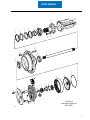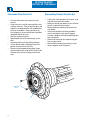
1
Spicer Hub
®
Service Manual
Spicer® Hub
AXSM-0052
September 2007
Page to Insert
General Information
The description and specifications contained in this
service publication are current at the time of printing.
Dana Corporation reserves the right to discontinue or
modify its models and/or procedures and to change
specifications at any time without notice.
Any reference to brand name in this publication is made
as an example of the types of tools and materials
recommended for use and should not be considered an
endorsement. Equivalents may be used.
IMPORTANT NOTICE
This symbol is used throughout this
manual to call attention to procedures
where carelessness or failure to follow
specific instructions may result in
personal injury and/or component
damage.
Departure from the instructions,
choice of tools, materials and recommended parts mentioned in this
publication may jeopardize the personal safety of the service technician
or vehicle operator.
!
!
!
WARNINGS: Failure to follow indicated procedures creates a high risk
of personal injury to the servicing
technician.
CAUTION: Failure to follow indicated
procedures may cause component
damage or malfunction.
NOTE: Additional service information not
covered in the service procedures.
Tip: Helpful removal and installation
procedures to aid in the service of this unit.
Always use genuine Spicer replacement parts.
Every effort has been made to ensure the accuracy of all information in this guide. However, Spicer Axle and
Brake Division makes no expressed or implied warranty or representation based on the enclosed information.
Any errors or omissions may be reported to:
Marketing Services, Dana Corporation, PO Box 321, Toledo, Ohio 43697-0321
1
General Information
Contents
General Information
Important Notice ....................................................................................................................................................................................... 1
HS 415 SM Model
Changing Oil ............................................................................................................................................................................................. 3
Service Instructions .................................................................................................................................................................................. 4
Removal of hub on vehicle ....................................................................................................................................................................... 5
Disassemble Planet Carrier Unit ............................................................................................................................................................... 6
Disassembling Planetary Ring Gear Unit .................................................................................................................................................. 6
Removing Hub Unit .................................................................................................................................................................................. 7
Assembly .................................................................................................................................................................................................. 8
Hub Bearing Setting .................................................................................................................................................................................. 9
Sub Assembly - Planet Carrier Unit ........................................................................................................................................................ 10
HS 515 SP, HD 519 SP, HS 716SQ, HD 719SQ
Hub Reduction Units ..............................................................................................................................................................................
Removal of hub on Vehicle .....................................................................................................................................................................
Disassemble Planet Carrier Unit .............................................................................................................................................................
Disassembling Planetary Ring Gear Unit ................................................................................................................................................
Removing Hub Unit ................................................................................................................................................................................
Assembly ................................................................................................................................................................................................
Hub Bearing Setting ................................................................................................................................................................................
Sub Assembly - Planet Carrier Unit ........................................................................................................................................................
12
13
14
14
15
16
17
18
Parts List for HS 515 SP, HD 519 SP Hub Unit
Assembly No. 964464 ............................................................................................................................................................................ 20
Assembly No. 964465 ............................................................................................................................................................................ 22
2
HS 415 SM Model
Changing oil
Note: New and reconditioned axles are greased
where necessary, but are not filled with oil when then
leave the manufacturing facility.
Drain and refill oil on new units after the first month
or 100 hours while axle is still warm, then at intervals
of 1,000 hours or 6 months.
Oil Level
Check oil levels monthly or every 100 hours following
the procedure below.
6. When level is correct, refit and tighten all filler/
level plugs.
Approximate capacities:
HS 415 SM - 6 pints (3.5 liters) per hub.
HS 515 SP - 8 pints (4.5 liters) per hub.
HP 519 SP - 8 pints (4.5 liters) per hub.
HS 716 SQ - 8 pints (4.5 liters) per hub.
HD 719 SQ - 8 pints (4.5 liters) per hub.
Recommended oil MIL-L-2105D.
1. Vehicle must be on level ground.
2. Remove differential oil filter plug and check oil
level. Add oil if necessary.
!
Warning: Never work under a vehicle supported
by only a jack. Always support vehicle with
stands. Block the wheels and make sure the
vehicle will not roll before releasing the brakes.
Note: Spicer recommends cleaning the magnetic
filler plug, drain plugs, and cleaning the breather.
Note: There is no oil sealing between the drive head
and hubs. Drive head and Hub oil levels should be on
the axle center line. When refilling add amounts
shown below to hubs then drive head and let sit in
axle for 15 minutes before checking levels at all
points. Add oil as necessary until level after settling
period.
Always check final oil level at drive head.
3. Raise the wheels off the ground and support with
proper stands.
4. Rotate each hub so the bottom of the hub filler/
level plugs are on the axle center line (level with
the differential filler plug).
5. Unscrew the plugs and check that oil level is at
the bottom of plug holes. If not, add oil to each
hub through plug holes then check level in drive
head.
3
HS 415 SM Model
Service Instructions For HS415SM Model
Description
The hub gears are driven by a floating sun pinion
which is splined to a drive shaft. The gear meets with
three planet gears mounted in a carrier which is
bolted to the hub. The ring gear is two pieces splined
to the axle spindle, it also serves to support the outer
hub bearing cone. The hub is fully floating, running
on a taper roller bearing which is secured and adjusted by a nut locking ring.
The unit is mounted on a removable spindle, bolted to
the axle housing.
Routine Maintenance
Service the vehicle every six months, checking the
following:
1. General condition of nuts, bolts and housing
2. Joints and seals for signs of leakage.
Tooling/Sealant List
Spring balance to read to 25 lbs. (12kg).
Hub nut spanner - E537.
Assembly tooling - E539.
Hub oil seal fitting tool - E540.
Loctite No. 277 locking compound.
Loctite No. 515 liquid gasket.
Loctite No. 609 sealing compound.
!
Caution: Viton O-rings and seals (flouro-elastomers) - safety hazards.
Viton material used in oil seals and O-rings
produces a highly corrosive acid (hydroflouric)
when subjected to temperatures above 315° C.
This acid is very toxic and should not be come in
contact with. We recommend the following
procedure when it is necessary to inspect any
equipment that has been subjected to high
temperature or fire.
a. Visually inspect any gaskets or seals that have
suffered from heat; they will appear black and
sticky.
4
b. If this condition exists, do not handle.
c. Confirm material composition. Any flouroelestomer (Viton, Flourel or Tecomoflon) should
be considered dangerous but natural rubber and
nitrile are nonhazardous.
d. If flouroelastomer seals have been used, the
affected area must be decontaminated before
continuing.
e. Disposable heavy duty gloves must be worn and
the affected area decontaminated by washing
thoroughly with limewater (calcium hydroxide
solution).
f.
Discard any clothing contaminated after use.
Note: Burning of discarded items is NOT RECOMMENDED, except in an approved incineration process
where gaseous products are treated by alkaline
scrubbing.
HS 415 SM Model
Removal of hub on vehicle
Note: Clean all parts in suitable cleaning agent.
Draining the oil
•
•
•
•
•
•
Before attempting to remove road wheels, drive
vehicle onto a level surface. Drain when lube is
at normal operating temperature.
Block the wheels and make sure the vehicle will
not roll.
Loosen but do not remove wheel nuts when
wheels are still on the ground.
Raise axle and support with suitable stands.
Remove wheel nuts and washers.
Remove wheels.
Note: As there is no oil sealing between drive heads
and hubs, oil must be drained from all three units
before overhaul.
•
•
•
•
•
•
•
•
Place containers under differential and both hubs.
Remove differential oil filler plug and drain bolt
and oil from differential.
Rotate hubs to bring carrier drain setscrews to
their lowest point.
Remove hub filler/level plug.
Remove drain setscrews and washers to drain oil
from hubs.
When oil in completely drained, remove drip tray
and support hub adequately.
Replace drain setscrews and washers and hub
filler/level plug.
Replace differential drain bolt.
5
HS 415 SM Model
Disassemble Planet Carrier Unit
Disassembling Planetary Ring Gear Unit
•
•
•
•
•
•
•
•
Unscrew and remove carrier capscrews and
washers.
Using chain hoist, carefully remove planet carrier
assembly from axle. Place on bench or press and
support in an upright position with outboard end
of carrier facing down. Remove planet pin by
first removing set screw and then press pin down
(outboard) and out of carrier.
Carefully remove planet gear.
Repeat operations for other planet gear assemblies.
Remove and discard O-rings from planet pins.
If thrust button needs changing, pull out of its
position in planet carrier inner face.
Remove sealing compound from planet carrier
and hub mating faces using Loctite Chisel Gasket
Remover or by carefully scraping sealant from
faces.
•
•
•
•
•
Pull out axle shaft complete with sun gear, snap
ring and washer from axle spindle.
Remove snap ring from groove in axle shaft then
pull off sun gear and thrust washer.
Remove lockrings and hub retaining nut from
axle spindle.
Insert extraction bolts into holes provided in ring
gear and tighten evenly to pull ring gear assembly, complete with outer hub bearing cone from
axle spindle.
Remove retraining ring then separate ring gear
from ring gear carrier.
Remove outer hub bearing cone from its position
on ring gear carrier if required.
16
11
EXTRACTION
BOLTS
12
ax-0138
6
HS 415 SM Model
Removing Hub Unit
•
•
•
•
Using suitable support, carefully remove hub
assembly from axle spindle and place on work
bench, outer end down.
Carefully remove oil seal outer half from hub then
lift inner hub bearing cone.
Inspect oil seal part for wear and damage.
Check hub bearing cups for wear and damage. If
necessary, remove cups from hub using soft
metal drift pin.
Note: If either bearing cup or cone needs replacing,
a new cup and cone must be fitted.
•
Inspect oil seal half parts and housing for wear
and damage.
Note: If any seal assembly parts need to be replaced,
a complete new assembly must be fitted.
•
Inspect condition of hub spacer, removing for
replacement if required.
Hub/Axle Stub subassembly
•
•
•
•
Heat oil seal housing until hand hot (120° C,
248°F max.), then push into position on axle
stub.
When oil seal housing has cooled, push bearing
spacer into position on axle stub.
Fill bearing cone with grease using a bearing
packer or manually kneading grease between
rollers, race and cage, then push into position on
axle stub.
Fit inner and outer hub bearing cups into position
on hub.
7
HS 415 SM Model
Assembly
•
•
•
•
Remove hub oil seal assembly from package, fit
one half into hub and other into inner seal
housing as follows:
Note: Keep oil off of other surfaces.
a. Do not remove seals from package until
immediately before installation. This protects
the super-finished seal faces from damage
and contamination.
b. Hub and oil seal housing must be clean.
c. Install face seal by means of special fitting
tool number E541. Pressure is applied
directly via the elastromeric part. For ease of
assembly moisten the bore and O-rings with
a water/spirit mixture (NOT OIL).
d. Press seal ring into hub/ seal housing using
even pressure on opposite sides of tool.
Ensure that the housing/hub surface 'A' lies
parallel to the seal face 'B'. The O-rings must
not be pinched in the hub/housing or partially
out of the bore.
•
•
Support hub with chain hoist, and carefully push
into position on axle spindle.
Assemble guide tube from assembly tooling E
539 onto axle spindle, carefully pushing into
position on axle spindle. Use bumper or soft
metal hammer from assembly tooling to ensure
ring gear is driven on completely.
Fit hub bearing nut and tighten hand tight.
Remove chain hoist.
•
•
Assemble ring gear and ring gear carrier together
and secure with ring gear retainer.
Press hub outer bearing cone onto ring gear
carrier journal.
Clean metal surfaces with a lint free cloth, apply a
thin film of clean oil to metal faces.
Housing / hub
A
A
A
B
B
B
Correct
8
Incorrect
HS 415 SM Model
Hub Bearing Setting
Torque hub nut to 190-210 lbs. ft. (258-285
N•m).
•
Note: The hub should be fully rotated several times
in both directions to ensure the hub bearings are
correctly seated.
•
•
•
•
•
If spring balance reading is outside limits stated,
adjust hub nut and check again, continuing until
correct figure is obtained.
When hub setting is correct, fit lockrings, then
retaining ring.
Note: To align slots in nut with corresponding slots
in axle spindle, do not back off. Continue to tighten
nut until slots are aligned.
Secure a cord to a wheel stud and wrap cord
around hub, fasten free end to a spring balance.
Apply a steady pull to spring balance and note
reading, ignoring the large force initially required
to start rotation.
The correct spring balance reading should be
between 6 to 10 lbs. (2.7 to 4.5 kg) corresponding to a hub rolling torque of 3-5 lbs. ft. (4-7
N•m).
16
12
10
WRAP CORD
AROUND HUB
SPRING
GUAGE
AX0139
9
HS 415 SM Model
Sub Assembly - Planet Carrier Unit
•
•
•
•
•
•
•
•
•
Place planet carrier with large diameter face up
with planet gear access hole facing the mechanic.
Smear clean grease into bore of one planet gear.
Insert planet gear and thrust washers into planet
carrier.
Lightly oil O-ring and O-ring grove in planet pin
with clear gear oil then fit O-ring into planet
carrier.
Insert planet pin, O-ring up into planet carrier and
through planet gear making sure to line up flat on
planet pin with hole in planet carrier for set
screw.
Clean set screw threads with solvent then apply
Loctite 275. Drive screw into hole in planet
carrier and tighten to a torque of 22-27 lbs. ft.
(30-36 N•m) to secure planet pin assembly.
Repeat operations for other two planet gear
assemblies.
Stake screw in four places to lock in position.
Coat thrust button bore, in planet carrier, with
Loctite 275 then fit thrust button.
Fitting Planet Carrier Unit/Final Assembly
•
•
•
•
•
•
•
•
10
Fit thrust washer, then sun gear onto axle shaft,
then fit snap ring to secure.
Apply clean gear oil to axle shaft inner splines.
Insert axle shaft assembly into axle spindle until
axle shaft splines are engaging with differential
gear splines.
Coat hub mating face of planet carrier with
Loctite 515 joining planet carrier unit with hub
using chain hoist if required. Ensure planet gear
teeth mesh with sun gear.
Fit planet carrier capscrews and hardened
washers, tighten to a torque of 91-101 lbs. ft.
(123-137 N•m).
Fit drain capscrew and washer, tighten to a torque
of 145-161 lbs. ft. (196-218 N•m).
Fit planet cover plate, secure with capscrew,
tightening to 66-72 lbs. ft. (89-98 N•m).
Rotate both hubs until oil filler/level plug holes
are on axle center line, fill with oil until level with
bottom of level hole thread.
Fill drive head with oil.
•
•
•
Allow oil to settle for 15 minutes, then check oil
level again in both hubs and differential.
Refit then tighten the filler/level plug then drive
head filler plug.
Refit road wheels securing with spherical washers and wheel nuts. Remove supports and lower
vehicle to ground. Tighten wheel nuts to a torque
of 400-430 lbs. ft. (542-583 N•m).
Note: The wheel nuts should be checked and
tightened if necessary, shortly after initial operation.
Tightening Torque Table
For Type HS 415 SM Hub
Item
No. Description
1
Planet carrier cover capscrew
6
Planet carrier set screw
10
Hub bearing retaining nut
14
Wheel nuts
27
Axle spindle retaining bolt
37
Planet carrier capscrew
39
Planet carrier drain capscrews
Torque
66-72 lbs. ft
(89-98 N•m)
22-27 lbs. ft.
(30-36 N•m)
190-210 lbs. ft.
(258-285 N•m)
400-430 lbs. ft.
(542-583 N•m)
390-410 lbs. ft.
(529-556 N•m)
91-101 lbs. ft.
(123-137 N•m)
145-161 lbs. ft
(196 - 218 N•m)
HS 415 SM Model
24
25
23
21
20
22
19
18
27
26
17
16
14 15
28A
30
28
29
29A
13
12
11
6
5
31
2
3
1
33
4
7
8
9
10
32
35
39
38
37 36
4
TYPE RP12
HUB REDUCTION UNIT
HS 415 SM
AX01
11
HS 515 SP, HD 519 SP,
HS716SQ, HD 719 SQ Models
Service Instructions for HS515SP, HD519SP,
HS716SQ, HD719SQ
Hub Reduction Units
Description
The hub gears are driven by a floating sun pinion
which is splined to a drive shaft. The sun gear meets
with three planet gears mounted to the carrier which
is bolted to the hub. The ring gear is two pieces and
splined to the axle spindle, it also supports the outer
hub bearing cone. The hub is fully floating, running
on taper roller bearings secured and adjusted by a nut
with locking ring.
The unit is connected with a removable spindle bolted
to the axle casing.
Routine Maintenance
Service vehicle every 6 months, check the following:
1. General condition of nuts, bolts and axle casing.
2. Joints / oil seals for signs of leakage.
Tooling/Sealant List
Spring balance to read 25 lbs. (12 kg.)
Outer bearing cone bumper - E534
Hub guide sleeve - E535
Ring gear carrier assembly tooling - E536
Hub nut spanner - E538
Hub oil seal fitting tool - E541
Loctite No. 277 locking compound
Loctite No. 515 liquid gasket
Loctite No. 609 sealing compound
Vision O-rings and seals (flour-elastomers) safety hazards
Caution: Viton O-rings and seals (flouro-elastomers) - safety hazards. Viton material used in
oil seals and O-rings produces a highly corrosive
acid (hydroflouric) when subjected to temperatures above 315° C. This acid is very toxic and
should not be come in contact with. We recommend the following procedure when it is necessary to inspect any equipment that has been
subjected to high temperature or fire.
12
a. Visually inspect any gaskets or seals that
have suffered from heat; they will appear
black and sticky.
b. If this condition exists, do not handle.
c. Confirm material composition. Any flouroelestomer (Viton, Flourel or Tecomoflon)
should be considered dangerous but natural
rubber and nitrile are nonhazardous.
d. If flouroelastomer seals have been used, the
affected area must be decontaminated before
continuing.
e. Disposable heavy duty gloves must be worn
and the affected area decontaminated by
washing thoroughly with limewater (calcium
hydroxide solution).
f. Discard any clothing contaminated after use.
Note: Burning of discarded items is NOT RECOMMENDED, except in an approved incineration process
where gaseous products are treated by alkaline
scrubbing.
HS 515 SP, HD 519 SP,
HS716SQ, HD 719 SQ Models
Removal of hub on vehicle
Note: Clean all parts in suitable cleaning agent.
Draining the oil
• Before attempting to remove road wheels, drive
vehicle onto a level surface. Drain when lube is
at normal operating temperature.
• Block the wheels and make sure the vehicle will
not roll.
• Loosen but do not remove wheel nuts when
wheels are still on the ground.
• Raise axle and support with suitable stands.
• Remove wheel nuts and washers.
• Remove wheels.
•
•
•
•
•
•
•
•
Place containers under diff. and both hubs.
Remove diff. oil filler plug and drain bolt and oil
from diff.
Rotate hubs to bring carrier drain setscrews to
their lowest point.
Remove hub filler/level plug.
Remove drain setscrews and washers to drain oil
from hubs.
When oil in completely drained, remove drip tray
and support hub adequately.
Replace drain setscrews and washers and hub
filler/level plug.
Replace diff. drain bolt.
Note: As there is no oil sealing between drive heads
and hubs, oil must be drained from all three units
before overhaul.
16
34
35
4
DRAIN
AX0140
13
HS 515 SP, HD 519 SP,
HS716SQ, HD 719 SQ Models
Disassemble Planet Carrier Unit
Disassembling Planetary Ring Gear Unit
•
•
•
•
•
•
•
•
Unscrew and remove carrier capscrews and
washers.
Using chain hoist, carefully remove planet carrier
assembly from axle. Place on bench or press and
support in an upright position with outboard end
of carrier facing down. Remove planet pin by
first removing set screw and then press pin down
(outboard) and out of carrier.
Carefully remove planet gear.
Repeat operations for other planet gear assemblies.
Remove and discard O-rings from planet pins.
If thrust button needs changing, pull out of its
position in planet carrier inner face.
Remove sealing compound from planet carrier
and hub mating faces using Loctite Chisel Gasket
Remover or by carefully scraping sealant from
faces.
•
•
•
•
•
16
11
EXTRACTION
BOLTS
12
ax-0138
14
Pull out axle shaft complete with sun gear, snap
ring and washer from axle spindle.
Remove snap ring from groove in axle shaft then
pull off sun gear and thrust washer.
Remove lockrings and hub retaining nut from
axle spindle.
Insert extraction bolts into holes provided in
annulus and tighten evenly to pull ring gear
assembly, complete with outer hub bearing cone
from axle spindle.
Remove retraining ring then separate ring gear
from ring gear carrier.
Remove outer hub bearing cone from its position on ring gear carrier if required.
HS 515 SP, HD 519 SP,
HS716SQ, HD 719 SQ Models
Removing Hub Unit
•
•
•
•
Using suitable support, carefully remove hub
assembly from axle spindle and place on work
bench, outer end down.
Carefully remove oil seal outer half from hub then
lift inner hub bearing cone.
Inspect oil seal part for wear and damage.
Check hub bearing cups for wear and damage. If
necessary, remove cups from hub using soft
metal drift pin.
Note: If either bearing cup or cone needs replacing,
a new cup and cone must be fitted.
•
Inspect oil seal half parts and housing for wear
and damage.
Note: If any seal assembly parts need to be replaced,
a complete new assembly must be fitted.
•
Inspect condition of hub spacer, removing for
replacement if required.
Hub/Axle Stub subassembly
•
•
•
•
Heat oil seal housing until hand hot (120° C,
248°F max.), then push into position on axle
stub.
When oil seal housing has cooled, push bearing
spacer into position on axle stub.
Fill bearing cone with grease using a bearing
packer or manually kneading grease between
rollers, race and cage, then push into position on
axle stub.
Fit inner and outer hub bearing cups into position
on hub.
15
HS 515 SP, HD 519 SP,
HS716SQ, HD 719 SQ Models
Assembly
•
Remove hub oil seal assembly from package, fit
one half into hub and other into inner seal
housing as follows:
a. Do not remove seals from package until
immediately before installation. This
protects the super-finished seal faces from
damage and contamination.
b. Hub and oil seal housing must be clean.
c. Install face seal by means of special fitting
tool number E541. Pressure is applied
directly via the elastromeric part. For ease
of assembly moisten the bore and O-rings
with a water/spirit mixture (NOT OIL).
d. Press seal ring into hub/ seal housing using
even pressure on opposite sides of tool.
Ensure that the housing/hub surface 'A' lies
parallel to the seal face 'B'. The O-rings
must not be pinched in the hub/housing or
partially out of the bore.
•
•
•
Note: Keep oil off of other surfaces.
•
Support hub with chain hoist, and carefully push
into position on axle spindle.
Assemble guide tube from assembly tooling E
539 onto axle spindle, carefully pushing into
position on axle spindle. Use bumper or soft
metal hammer from assembly tooling to ensure
annulus is driven on completely.
Fit hub bearing nut and tighten hand tight.
Remove chain hoist.
•
•
•
Assemble ring gear and ring gear carrier together and secure with ring gear retainer.
Press hub outer bearing cone onto ring gear
carrier journal.
Clean metal surfaces with a lint free cloth, apply
a thin film of clean oil to metal faces.
Housing / hub
A
A
A
B
B
B
Correct
16
Incorrect
HS 515 SP, HD 519 SP,
HS716SQ, HD 719 SQ Models
Hub Bearing Setting
•
Torque hub nut to 238-263 lbs. ft. (323-357
N•m).
Note: The hub should be fully rotated several times
in both directions to ensure the hub bearings are
correctly seated.
•
•
•
•
•
Secure a cord to a wheel stud and wrap cord
around hub, fasten free end to a spring balance.
Apply a steady pull to spring balance and note
reading, ignoring the large force initially required
to start rotation.
The correct spring balance reading should be
between 8.5 to 12 lbs. (3.8 to 5.4 kg) corresponding to a hub rolling torque of 7-9 lbs. ft. (912 N•m).
If spring balance reading is outside limits stated,
adjust hub nut and check again, continuing until
correct figure is obtained.
When hub setting is correct, fit lockrings, then
retaining ring.
Note: To align slots in nut with corresponding slots
in axle spindle, do not back off. Continue to tighten
nut until slots are aligned.
16
12
10
WRAP CORD
AROUND HUB
SPRING
GUAGE
AX0139
17
HS 515 SP, HD 519 SP,
HS716SQ, HD 719 SQ Models
Sub Assembly - Planet Carrier Unit
•
•
•
•
•
•
•
•
•
Place planet carrier with large diameter face up
with planet gear access hole facing the mechanic.
Smear clean grease into bore of one planet gear.
Insert planet gear and thrust washer into planet
carrier.
Lightly oil O-ring and O-ring grove in planet pin
with clear gear oil then fit 'O'ring into planet pin.
Insert planet pin, O-ring up into planet carrier and
through planet gear making sure to line up flat on
planet pin with hole in planet carrier for set
screw.
Clean set screw threads with solvent then apply
Loctite 275. Drive screw into hole in planet
carrier and tighten to a torque of 22-27 lbs. ft.
(30-36 N•m) to secure planet pin assembly.
Repeat operations for other two planet gear
assemblies.
Stake screw in four places to lock in position.
Coat thrust button bore, in planet carrier, with
Loctite 275 then fit thrust button.
Fitting Planet Carrier Unit/Final Assembly
•
•
•
•
•
•
•
•
•
18
Fit thrust washer, then sun gear onto axle shaft,
then fit snap ring to secure.
Apply clean gear oil to axle shaft inner splines.
Insert axle shaft assembly into axle spindle until
axle shaft splines are engaging with differential
gear splines.
Coat hub mating face of planet carrier with
Loctite 515 joining planet carrier unit with hub
using chain hoist if required. Ensure planet gear
teeth mesh with sun gear.
Fit planet carrier capscrews and hardened
washers, tighten to a torque of 91-101 lbs. ft.
(123-137 N•m).
Fit drain capscrew and washer, tighten to a torque
of 145-161 lbs. ft. (196-218 N•m).
Fit planet cover plate, secure with capscrew,
tightening to 66-72 lbs. ft. (89-98 N•m).
Rotate both hubs until oil filler/level plug holes
are on axle center line, fill with oil until level with
bottom of level hole thread.
Fill drive head with oil.
Allow oil to settle for 15 minutes, then check oil
level again in both hubs and diff.
•
•
Refit then tighten the filler/level plug then drive
head filler plug.
Refit road wheels securing with spherical washers and wheel nuts. Remove supports and lower
vehicle to ground. Tighten wheel nuts to a torque
of 400-430 lbs. ft. (542-583 N•m).
Note: The wheel nuts should be checked and
tightened if necessary, shortly after initial operation.
Tightening Torque Table for Type
HS 515 SP, HD 519 SP,
HS 716 SQ, HD 719 SQ
Item
No. Description
1
Planet carrier cover capscrew
9
Planet carrier set screw
17
Hub bearing retaining nut
22
Wheel nuts
34
Axle spindle retaining bolt
38
Planet carrier capscrew
39
Planet carrier drain capscrews
Torque
66-71 lbs. ft.
(89-98 N•m)
22-27 lbs. ft.
(30-36 N•m)
238-263 lbs. ft.
(323-357 N•m)
400-420 lbs. ft.
(542-583 N•m)
390-410 lbs. ft.
(529-556 N•m)
91-101 lbs. ft.
(123-137 N•m)
145-151 lbs. ft.
(196-218 N•m)
HS 515 SP, HD 519 SP,
HS716SQ, HD 719 SQ Models
31
32
30
29
28
27
26
25A
25
34
33
24
23
22
14
20
21
19
21A
18
8
7
6
9
12
2
3
1
10
4
13
15
16
17
11
39
38 37
AX-0137
36
35
5
TYPE RP16
HUB REDUCTION UNIT
HS 515 SP, HD 519 SP,
HS 716 SP, HD 719 SQ
19
HS 515 SP, HD 519 SP,
Hub Unit
Parts List for HS515SP, HD519SP Hub Unit
Item No.
1
2
3
4
5
6
7
8
9
10
11
12
13
14
15
16
17
18
19
20
21
21A
22
23
24
25
25QA
26 to 29
30
31
32
33
34
35
35
36
37
38
39
20
Description
Planet carrier cover capscrew
Planet carrier cover
'O' ring
Planet pin
Planet carrier
Planet pin thrust washer
Planet gear
Planet pin thrust washer
Planet pin retainer setscrew
Thrust button
Sun gear snap ring
Sun gear
Sun gear thrust washer
Drive shaft
Hub nut snap ring
Hub nut lock ring
Hub nut
Ring gear
Ring gear carrier
Ring gear snap ring
Bearing cup (outer)
Bearing cone (outer)
Wheel nut (supplied by customer)
Hub
Wheel stud
Bearing cup (inner)
Bearing cone (inner)
Hub oil seal assembly
Oil seal retainer
Axle housing assembly
Spindle
Axle spindle washer
Spindle bolt
Planet carrier washer
Spindle bolt
Planet carrier capscrew
Oil drain washer
Oil drain capscrew
Level plug
Assembly No. 964464
Qty Per Axle
12
2
6
6
2
6
6
6
6
2
2
2
2
2
2
4
2
2
2
2
2
2
38
2
38
2
2
2
2
1
2
28
28
46
14
46
2
2
2
GKN Part No. Spicer Part No.
N70134
R9902/29
N60410
R9611/42
R9899/39
N40457
R9611/37
N40457
N70090
N40450
N60017
R9611/38
N40741
R9899/46A
N60332
N40998
N40995
R9611/36
R9611/9
N40458
SL289/389
SL289/390
965201
96557
965167
965707
965717
964989
965705
964989
963972
963935
965142
965706
965011
965718
965161
965022
965021
965704
965708
964990
965724
965725
R9899/114
R9893/137
SL320/57
SL320/58
SR9899/187
R9899/81
R9893/240
R9899/238
N70040
N70005
SL238/5
N70006
N70196
N70200
N70137
N70042
965715
965756
027816
965727
965729
965719
965666
965716
963970
965176
964281
963977
963978
963974
963971
Assy. No. 964463
Axle Assembly No. 964463 is same as 964464 except for the following parts:
14
31
Axle shaft RH
Axle shaft LH (lock side)
Axle Housing
Also required, but not illustrated:
Assembly no. 964464
Axle housing stud
Axle housing nut
Axle housing capscrew
Axle housing washer
Filler/level & drain plug
Filler/level & drain plug 'O' ring
1
1
1
R9908/46A
R9902/46A
R9899/240
4
4
8
12
2
2
R9893/184
SL221/5
R9390/90
SL242/5
R9893/22
R9893/149
4
4
8
12
2
2
R9896/184
R9899/68
ML6016/40X
ML5716/1
R9893/22
R9893/149
Assembly no. 964463
Axle housing stud
Axle housing nut
Axle housing setscrew
Axle housing washer
Filler/level & drain plug
Filler/level & drain plug 'O' ring
21
Parts List For HS726SQ
Parts List For HS716SQ Hub Unit
1
2
3
4
5
6
7
8
9
10
11
12
13
14
15
16
17
18
19
20
21
21A
22
23
24
25
25A
26 to 29
30
31
32
33
34
35
35
36
37
38
39
22
Assembly No. 964465
Planet carrier cover capscrew
Planet carrier cover
'O' ring
Planet pin
Planet carrier
Planet pin thrust washer
Planet gear
Planet pin thrust washer
Planet pin retainer set screw
Thrust button
Sun gear snap ring
Sun gear
Sun gear thrust washer
Axle shaft LH-(lock side)
Axle shaft RH
Hub nut snap ring
Hub nut lock ring
Hub nut
Ring gear
Ring gear carrier
Ring gear snap ring
Bearing cup (outer)
Bearing cone (outer)
Wheel nut (supplied by customer)
Hub
Wheel stud
Bearing cup (inner)
Bearing cone (inner)
Hub oil seal assembly
Oil seal retainer
Axle housing assembly
Spindle
Axle spindle washer
Spindle bolt
Planet carrier washer
Stub bolt
Planet carrier capscrew
Oil drain washer
drain capscrew
Level plug
12
2
6
6
2
6
6
6
6
2
2
2
2
1
1
2
4
2
2
2
2
2
2
N70134
R9902/29
N60410
N40506
N40723
N50200
N50200
N40457
N70090
N40450
N60099
N50203
N40891
R9905/4A
R9896/46A
N60332
N40998
N40995
N50201
R9611/9
N40458
SL289/389
SL289/390
2
38
2
2
2
2
1
2
28
28
46
14
46
2
2
2
R9896/114
R9893/137
SL289/247
SL289/180
SR9899/187
R9899/81
R9896/240
R9899/238
N70040
N70005
SL238/5
N70006
N70196
N70200
N70137
N70042
Axle Assy. No. 964466
Hub assembly no. 964466 is same as 964465 except for following parts:
14
31
Axle shaft
Axle housing
2
1
R9911/46A
R9911/240
Hub assembly No. 964467 is same as 964465 except for the following parts:
14
31
Axle shaft RH
Axle shaft LH (lock side)
Axle housing
1
1
1
R9896/46B
R9905/46B
R9905/240
Assembly no. 964465 & 964467
Axle housing stud
Axle housing nut
Axle housing capscrew
Axle housing washer
Filler/level & drain plug
Filler/level & drain plug O-ring
4
4
8
12
2
2
R9896/184
R9899/68
ML6016/40X
ML5712/1
R9893/22
R9893/149
4
4
8
12
2
2
R9911/184
R9911/68
R9911/90
ML5712/1
R9893/22
R9893/149
Assembly no. 964466
Axle housing stud
Axle housing nut
Axle housing capscrew
Axle housing washer
Filler/level & drain plug
Filler/level & drain plug O-ring
23
Aftermarket
Group
ForDana
spec‘ing
or service assistance,
call 1.800.621.8084 or visit our website at www.spicerparts.com
PO Box 321
Toledo, Ohio 43697-0321
Warehouse
Distributor:
Dana
Commercial
Vehicle1.800.621.8084
Products Group
OE Technology
Dealers: 1.877.777.5360
3939
Drive
Maumee, Ohio, USA 43537
www.spicerparts.com
www.dana.com
AXSM-0052 Printed in U.S.A.
Copyright Dana Limited, 2012.
All rights reserved. Dana Limited.