1
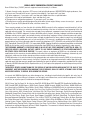
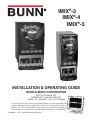
IMIX®-3
IMIX®-4
IMIX®-5
INSTALLATION & OPERATING GUIDE
BUNN-O-MATIC CORPORATION
POST OFFICE BOX 3227
SPRINGFIELD, ILLINOIS 62708-3227
PHONE: (217) 529-6601 FAX: (217) 529-6644
To ensure you have the latest revision of the Operating Manual, or to view the Illustrated Parts
Catalog, Programming Manual, or Service Manual, please visit the Bunn-O-Matic website, at
www.bunn.com. This is absolutely FREE, and the quickest way to obtain the latest catalog and
manual updates. For Technical Service, contact Bunn-O-Matic Corporation at 1-800-286-6070.
37510.0000P
03/15 ©2004 Bunn-O-Matic Corporation
BUNN-O-MATIC COMMERCIAL PRODUCT WARRANTY
Bunn-O-Matic Corp. (“BUNN”) warrants equipment manufactured by it as follows:
1) Airpots, thermal carafes, decanters, GPR servers, iced tea/coffee dispensers, MCR/MCP/MCA single cup brewers, thermal servers and ThermoFresh® servers (mechanical and digital) 1 year parts and 1 year labor.
2) All other equipment - 2 years parts and 1 year labor plus added warranties as specified below:
a) Electronic circuit and/or control boards - parts and labor for 3 years.
b) Compressors on refrigeration equipment - 5 years parts and 1 year labor.
c) Grinding burrs on coffee grinding equipment to grind coffee to meet original factory screen sieve analysis - parts and
labor for 4 years or 40,000 pounds of coffee, whichever comes first.
These warranty periods run from the date of installation BUNN warrants that the equipment manufactured by it will be
commercially free of defects in material and workmanship existing at the time of manufacture and appearing within the
applicable warranty period. This warranty does not apply to any equipment, component or part that was not manufactured
by BUNN or that, in BUNN’s judgment, has been affected by misuse, neglect, alteration, improper installation or operation,
improper maintenance or repair, non periodic cleaning and descaling, equipment failures related to poor water quality,
damage or casualty. In addition, the warranty does not apply to replacement of items subject to normal use including but
not limited to user replaceable parts such as seals and gaskets. This warranty is conditioned on the Buyer 1) giving BUNN
prompt notice of any claim to be made under this warranty by telephone at (217) 529-6601 or by writing to Post Office Box
3227, Springfield, Illinois 62708-3227; 2) if requested by BUNN, shipping the defective equipment prepaid to an authorized
BUNN service location; and 3) receiving prior authorization from BUNN that the defective equipment is under warranty.
THE FOREGOING WARRANTY IS EXCLUSIVE AND IS IN LIEU OF ANY OTHER WARRANTY, WRITTEN OR ORAL, EXPRESS OR IMPLIED, INCLUDING, BUT NOT LIMITED TO, ANY IMPLIED WARRANTY OF EITHER MERCHANTABILITY
OR FITNESS FOR A PARTICULAR PURPOSE. The agents, dealers or employees of BUNN are not authorized to make
modifications to this warranty or to make additional warranties that are binding on BUNN. Accordingly, statements by such
individuals, whether oral or written, do not constitute warranties and should not be relied upon.
If BUNN determines in its sole discretion that the equipment does not conform to the warranty, BUNN, at its exclusive option while the equipment is under warranty, shall either 1) provide at no charge replacement parts and/or labor (during the
applicable parts and labor warranty periods specified above) to repair the defective components, provided that this repair
is done by a BUNN Authorized Service Representative; or 2) shall replace the equipment or refund the purchase price for
the equipment.
THE BUYER’S REMEDY AGAINST BUNN FOR THE BREACH OF ANY OBLIGATION ARISING OUT OF THE SALE OF THIS
EQUIPMENT, WHETHER DERIVED FROM WARRANTY OR OTHERWISE, SHALL BE LIMITED, AT BUNN’S SOLE OPTION
AS SPECIFIED HEREIN, TO REPAIR, REPLACEMENT OR REFUND.
In no event shall BUNN be liable for any other damage or loss, including, but not limited to, lost profits, lost sales, loss of
use of equipment, claims of Buyer’s customers, cost of capital, cost of down time, cost of substitute equipment, facilities
or services, or any other special, incidental or consequential damages.
392, A Partner You Can Count On, Air Infusion, AutoPOD, AXIOM, BrewLOGIC, BrewMETER, Brew Better Not Bitter, BrewWISE, BrewWIZARD, BUNN Espress, BUNN Family Gourmet, BUNN Gourmet, BUNN Pour-O-Matic, BUNN, BUNN with
the stylized red line, BUNNlink, Bunn-OMatic, Bunn-O-Matic, BUNNserve, BUNNSERVE with the stylized wrench design,
Cool Froth, DBC, Dr. Brew stylized Dr. design, Dual, Easy Pour, EasyClear, EasyGard, FlavorGard, Gourmet Ice, Gourmet
Juice, High Intensity, iMIX, Infusion Series, Intellisteam, My Café, Phase Brew, PowerLogic, Quality Beverage Equipment
Worldwide, Respect Earth, Respect Earth with the stylized leaf and coffee cherry design, Safety-Fresh, savemycoffee.com,
Scale-Pro, Silver Series, Single, Smart Funnel, Smart Hopper, SmartWAVE, Soft Heat, SplashGard, The Mark of Quality in
Beverage Equipment Worldwide, ThermoFresh, Titan, trifecta, TRIFECTA (sylized logo), Velocity Brew, Air Brew, Beverage
Bar Creator, Beverage Profit Calculator, Brew better, not bitter., Build-A-Drink, BUNNSource, Coffee At Its Best, Cyclonic
Heating System, Daypart, Digital Brewer Control, Element, Milk Texturing Fusion, Nothing Brews Like a BUNN, Picture
Prompted Cleaning, Pouring Profits, Signature Series, Sure Tamp, Tea At Its Best, The Horizontal Red Line, Ultra are either
trademarks or registered trademarks of Bunn-O-Matic Corporation. The commercial trifecta® brewer housing configuration is a trademark of Bunn-O-Matic Corporation.
2
37510 031514
USER NOTICES
The notices on this dispenser should be kept in good condition. Replace unreadable or damaged labels.
! WARNING
HOT
DO NOT OVERLOAD CIRCUIT.
ALWAYS ELECTRICALLY GROUND
THE CHASSIS OR ADAPTOR PLUG.
DO NOT DEFORM PLUG OR CORD.
FOLLOW NATIONAL AND LOCAL
ELECTRICAL CODES.
KEEP COMBUSTIBLES AWAY.
LIQUID
RELEASE BUTTON WHEN CUP IS 3/4 FULL
PLACE
CUP
HERE
PLACE
CUP
HERE
FAILURE TO COMPLY RISKS EQUIPMENT
DAMAGE, FIRE OR SHOCK HAZARD.
PLACE
CUP
HERE
IMIX-3 (Self Serve)
28328.0011
READ THE ENTIRE
OPERATING MANUAL BEFORE
USING THIS PRODUCT
HOT
00986.0000E 5/98 ©1994 Bunn-O-Matic Corporation
LIQUID
00831.0000
PLACE
CUP
HERE
As directed in the International Plumbing Code of the
International Code Council and the Food Code
Manual of the Food and Drug Administration (FDA),
this equipment must be installed with adequate
backflow prevention to comply with federal, state
and local codes. For models installed outside the
U.S.A., you must comply with the applicable Plumbing /Sanitation Code for your area.
PLACE
CUP
HERE
PLACE
CUP
HERE
IMIX-3 (Portion Control)
28328.0013
HOT
LIQUID
00656.0001
RELEASE BUTTON WHEN CUP IS 3/4 FULL
PLACE
CUP
HERE
PLACE
CUP
HERE
Artwork for P/N: 00656.0001
Artwork Rev: A
Drawn: REF
Date: 04/22/10
PLACE
CUP
HERE
PLACE
CUP
HERE
IMIX-4 (Self Serve)
28328.0012
! WARNING
HOT
LIQUID
PLACE
CUP
HERE
PLACE
CUP
HERE
PLACE
CUP
HERE
PLACE
CUP
HERE
IMIX-4 (Portion Control)
28328.0014
37881.0000
IMIX-5 (Self Serve)
28328.0010
00824.0002
IMIX-5 (with Hot Water Dispense)
28328.0017
3
37510 072513
CE REQUIREMENTS
• This appliance must be installed in locations where it can be overseen by trained personnel.
• For proper operation, this appliance must be installed where the temperature is between 5°C to 35°C.
• Appliance shall not be tilted more than 10° for safe operation.
• An electrician must provide electrical service as specified in conformance with all local and national codes.
• This appliance must not be cleaned by water jet.
• This appliance can be used by persons aged from 18 years and above if they have been given supervision or
instruction concerning use of the appliance in a safe way and if they understand the hazards involved.
• Keep the appliance and its cord out of reach of children aged less than 18 years.
• Appliances can be used by persons 18 years and above with reduced physical, sensory or mental capabilities
or lack of experience and knowledge if they have been given supervision or instruction concerning use of the
appliance in a safe way and understand the hazards involved.
• Children under the age of 18 years should be supervised to ensure they do not play with the appliance.
• If the power cord is ever damaged, it must be replaced by the manufacturer or authorized service personnel
with a special cord available from the manufacturer or its authorized service personnel in order to avoid a hazard.
• Machine must not be immersed for cleaning.
• Cleaning and user maintenance shall not be made by children unless they are older than 18 years and supervised.
• This appliance is intended to be used in household and similar applications such as:
– staff kitchen areas in shops, offices and other working environments;
– by clients in hotels, motels and other residential type environments;
– bed and breakfast type environments.
• This appliance not intended to be used in applications such as:
– farm houses;
• Access to the service areas permitted by Authorized Service personnel only.
• The A-Weighted sound pressure level is below 70 dBA.
NORTH AMERICAN REQUIREMENTS
• This appliance must be installed in locations where it can be overseen by trained personnel.
• For proper operation, this appliance must be installed where the temperature is between 41°F to 95°F (5°C to
35°C).
• Appliance shall not be tilted more than 10° for safe operation.
• An electrician must provide electrical service as specified in conformance with all local and national codes.
• This appliance must not be cleaned by pressure washer.
• This appliance can be used by persons aged from 18 years and above if they have been given supervision or
instruction concerning use of the appliance in a safe way and if they understand the hazards involved.
• Keep the appliance and its cord out of reach of children aged less than 18 years.
• Appliances can be used by persons 18 years and above with reduced physical, sensory or mental capabilities
or lack of experience and knowledge if they have been given supervision or instruction concerning use of the
appliance in a safe way and understand the hazards involved.
• Children under the age of 18 years should be supervised to ensure they do not play with the appliance.
• If the power cord is ever damaged, it must be replaced by the manufacturer or authorized service personnel
with a special cord available from the manufacturer or its authorized service personnel in order to avoid a hazard.
• Machine must not be immersed for cleaning.
• Cleaning and user maintenance shall not be made by children unless they are older than 18 years and supervised.
• This appliance is intended for commercial use in applications such as:
– staff kitchen areas in shops, offices and other working environments;
– by clients in hotel and motel lobbies and other similar types of environments;
• Access to the service areas permitted by Authorized Service personnel only.
4
37510 030215
INITIAL SET-UP
1. Apply the four non-skid pads from the parts box to the bottom of the legs.
2. Remove the drip tray assembly, drip tray bracket, and splash panel assembly from the parts box.
3. Place a set of key holes in the drip tray bracket over the lower two screws in the panel below the hopper
access door; push down gently and tighten screws.
4. Place the set of key holes in the splash panel over the upper two screws and position so the screws are
between the holes.
ELECTRICAL REQUIREMENTS
CAUTION - The dispenser must be disconnected from the power source until specified in Electrical Hook-Up.
The 120 volt version of this dispenser has an attached cordset. The mating connector must be a NEMA
5-15R.
To access terminal block for high voltage models without a cordset, remove left side panel.
BLK
WHI
L1
220-240V. A.C.
L2
GRN/YEL
GREEN
GRN/YEL
GREEN
220-240V AC
single phase models
Electrical Hook-Up
Note: This electrical service
consists of 2 current carrying conductors (L1 and L2)
and a separate conductor
for earth ground.
CAUTION - Improper electrical installation will damage electronic components.
1. An electrician must provide electrical service as specified.
2. Using a voltmeter, check the voltage and color coding of each conductor at the electrical source.
3. Place the ON/OFF/NIGHT switch in the “ON” position.
4. Connect the dispenser to the power source.
5. If plumbing is to be hooked up later be sure the dispenser is disconnected from the power source. If plumbing has been hooked up, the dispenser is ready for Initial Fill & Heat.
5
37510 051311
PLUMBING REQUIREMENTS
This dispenser must be connected to a cold water system with operating pressure between 20 and 90 psi (138
to 620 kPa) from a 1⁄2” or larger supply line. A shut-off valve should be installed in the line before the dispenser.
Install a regulator in the line when pressure is greater than 90 psi (690 kPa) to reduce it to 50 psi (345 kPa).
The water inlet fitting is 1⁄4” flare.
NOTE - Bunn-O-Matic recommends 1⁄4” copper tubing for installations of less than 25 feet and 3⁄8” for more
than 25 feet from the 1⁄2” water supply line. At least 18 inches of an FDA approved flexible beverage tubing,
such as reinforced braided polyethylene or silicone, before the dispenser will facilitate movement to clean the
countertop. Bunn-O-Matic does not recommend the use of a saddle valve to install the dispenser. The size and
shape of the hole made in the supply line by this type of device may restrict water flow.
As directed in the International Plumbing Code of the International Code Council and the Food Code
Manual of the Food and Drug Administration (FDA), this equipment must be installed with adequate
backflow prevention to comply with federal, state and local codes. For models installed outside the
U.S.A., you must comply with the applicable Plumbing /Sanitation Code for your area.
NOTE - If a backflow preventer is required by code, a shock arrestor should be installed between backflow preventer and dispenser. Installing the shock arrestor as close to the dispenser as possible will provide the best
results.
NOTE - Water pipe connections and fixtures directly connected to a potable water supply shall be sized, installed
and maintained in accordance with federal, state and local codes.
PLUMBING HOOK-UP
1. Flush the water line and securely attach it to the elbow fitting on the bottom of the dispenser.
2. Turn on the water supply.
INITIAL FILL & HEAT
1. Turn on the water supply and connect the dispenser to the power source.
2. Water will automatically flow into the tank to the proper level and then shut-off. This will take less than ten
minutes.
3. When the tank is full of water, open the front door and place the ON/OFF/NIGHT switch in the “ON” (upper)
position. A tank full of cold water will take approximately eighty minutes for the water to heat on 120 volt
versions, and forty minutes on 120/240 volt and 220-240 volt versions.
4. Fill the hopper(s) with the dry product to be dispensed.
PRESET TANK TEMPERATURE
Tank temperatures have been preset at the factory to 180°F (82°C). Bunn recommends that to provide the
best quality beverage, the installer adjust the tank temperature to the powder product manufacturer’s recommended temperature for the hot powder product being used.
LIQUID LEVEL CONTROL
The system automatically maintains the hot water tank’s level by energizing the refill solenoid when the
water level drops below the liquid level probe. If the system has not successfully refilled in 10 minutes, a refill
error occurs. When a refill error occurs, the refill solenoid is de-energized. Once the cause of the refill error has
been investigated and cured, the system can be reset by either disconnecting (for at least 5 seconds) and then
reconnecting the power to the machine, or by entering one of the program modes (see Programming Modes.)
6
37510 120513
RINSE TIMER
The dispenser is shipped from the factory with the rinse timer disabled. To enable the rinse timer, refer to
Programming the Dispenser and select yes in the “Rinse Alarm ?” screen; set timer to the desired time and
exit the programming mode.
When enabled, the rinse timer automatically keeps track of the time since the dispenser was last run through
a rinse sequence. If the dispenser detects that a rinse sequence has not been run for the desired time, a message will appear on the LCD display. If the Lockout is set, after an additional 4 hours, a rinse cycle has still not
been run, the LCD display will display a message, and the hopper drives will be disabled until a rinse sequence
has been run.
RUNNING A RINSE SEQUENCE
1. Place the Normal/Program/Rinse switch (page 10) in the “rinse” position.
2. Sequentially at each position, press all of the dispense switches. The dispenser will run for 10 seconds
with the hopper(s) disabled.
3. As each position is rinsed, the LCD display will show which position is being rinsed and count down from
10 seconds.
4. After all positions have been rinsed, return the Normal/Program/Rinse switch to the “Normal” position.
DISPENSER USE - Self Serve
1. Simply place a cup on the drip tray beneath the desired dispensing tip.
2. Press the button to froth and dispense the beverage.
3. Release the button when the cup is approximately 3/4 full and allow the mixing chamber to drain.
Note - The mixing chamber must drain at the end of each dispense.
DISPENSER USE - Portion Control
1. Simply place a cup on the drip tray beneath the desired dispensing tip.
2. Select the appropriate button for the cup size under the dispense tip, press momentarily, then release.
3. Let the mixing chamber completely drain before removing cup.
HOT WATER DISPENSE - IMIX-5 only
1. Simply place a cup on the drip tray beneath the hot water dispense arrow.
2. Press the button to dispense hot water.
3. Release the button when the desired amount is reached.
PREVENTIVE MAINTENANCE
Bunn-O-Matic® Corporation recommends that preventive maintenance be performed at regular intervals. Maintenance
should be performed by a qualified service technician. For Technical Service, contact Bunn-O-Matic® Corporation at
1-800-286-6070.
NOTE: Replacement parts or service caused by failure to perform required maintenance is not covered by warranty.
Cycle
Item
(months)
6
Mixing Chamber Kit
3 or as
needed
Whipper Shaft Seal Kit
Part Number
32906.0001
26356.1000
7
37510 051311
CLEANING
The use of a damp cloth rinsed in any mild, non-abrasive, liquid detergent is recommended for cleaning all surfaces on Bunn-O-Matic equipment. Do NOT clean this equipment with a water jet device.
1 x 24h
1. Rinse out Whipper Chambers by placing RINSE/RUN
switch in the "RINSE" position and activating DISPENSE
switches.
2. Turn elbow up, remove Hoppers, refill with product and
replace hoppers into dispenser.
3. Empty Drip Tray and wash in a solution of dish detergent.
7
1. Para limpiar las camaras de mezcla, coloque el interruptor en la
posicón ENJUAGUE/MARCHA (”RINSE/RUN”) y pulse el boton
para espumar y distribuir la bebida (”DISPENSE”).
2. Gire el codo hacia arriba, remueva las tolvas, llene las tolvas con
producto y coloque las tolvas nuevamente en la maquina.
3. Vacie la bandeja de goteo y limpiela con un detergente liquido
suave no abrasivo.
1 x 7d
8
Whipper Models only
Modelos batidor sólo
1
5
2
7
6
4
3
or
a. Wash
b. Rinse
c. Sanitize
d. Dry
a
b
a. Lave
b. Enjuague
c. Desinfecte
d. Seque
c
NOTICE
The cleaning instructions noted above are for non-dairy sugar based food products. When dispensing any other food product,
the cleaning cycle for the whipping chamber assembly and ejector elbow must be performed daily.
NOTA:
Las instrucciones de limpieza descritas anteriormente excluyen productos lacteos azucarados. La limpieza de las camaras
de mezcla y de los codos de salida de cada tolva deberá realizarse diariamente.
37254.0003A 02/13 © 2013 BUNN-O-MATIC CORPORATION
8
37510 072513
HOPPER DISPENSE RATE OF PRODUCT
The hopper dispense rates are preset at the factory. With 22 tooth gear and auger wire, the preset dispense
rate is approximately 3 to 5 grams per second. With 30 tooth gear and auger wire, the preset dispense rate is
approximately 5 to 7 grams per second. The hopper dispense rates can be individually programmed to a range
of dispense rates from approximately 1.5 to 12 grams per second, by following the procedures described in
Programming Modes.
HOPPER LEVEL SENSOR CALIBRATION
The dispenser is equipped with sensors to detect a low level in each hopper. When low powder lockout is
enabled, dispensing will be disabled when a low powder condition is detected in a hopper. The LCD screen on
the door will also display a low level condition.
The despenser is shipped from the factory with the low level powder lock disabled. To enable the lock,
place the “NORMAL/PROGRAM/RINSE” switch (page 10) in the “PROGRAM” position. Press button A (page
10) below the BUNN logo on the front of the door. Continue to press this button until the “LOCKS/DISABLES?”
menu is reached. Press button B (page 10} for “YES”, then press it again in the “LOW POWDER LOCK?” menu.
The low powder lockout is now enabled. Press button C (page 10) to exit the program menus, then return the
“NORMAL/PROGRAM/RINSE” button to the “NORMAL” position. To disable the low powder lockout, repeat the
process, and press button D (page 10) for “NO”, in the “LOW POWDER LOCK” menu.
The low level sensors are factory calibrated for most products. If calibration is required for proper operation, the sensors can be recalibrated to the current product.
The hopper must be at least half full of product for calibration. Place the “NORMAL/PROGRAM/RINSE”
switch in the “PROGRAM” position. Using button A (page 10), forward until the “CALIBRATION?” menu is
reached. Press button B (page 10) for “YES”, then press button A (page 10) until “CAL HOPPER 1?” screen is
reached. Continue to press button A until the hopper to be calibrated is reached.
To calibrate the hopper, press button B (page 10) to indicate “YES” in the “CAL HOPPER#? screen. The
screen will then ask you if the hopper is full. Press the button again to indicate “YES”. The calibration will then
take a few moments, then the screen will display “POWDER LEVEL RESET COMPLETE”. The next hopper may
be calibrated by moving forward in the menu, or press button C (page 10) to exit.
DRAINING THE HOT WATER TANK
CAUTION - The dispenser must be disconnected from the power source throughout these steps
1. Disconnect the dispenser from the power source.
2. Open front door and place ON/OFF/NIGHT switch in the “OFF” (center) position and let the water in the tank
cool before draining.
3. Shut off and disconnect the incoming water supply.
4. Remove the drip tray and access panels below the door.
5. Pull the clamped end of the silicone tube out of the dispenser and direct it into a drain or a container large
enough to hold the volume of water in the tank (7.3 gal for iMIX-4/5 and 4.4 gal for iMIX-3).
6. Make certain the shut off clamp is locked tightly on the tube, then remove the snap type clamp and plug from
end of tube.
7. Carefully release the shut off clamp to let the water drain from the tank.
NOTE - The dispenser must be refilled using the INITIAL FILL & HEAT steps before reconnecting to the power
source.
DOOR GRAPHIC AND LENS INSTALLATION
Remove the clear lens from the door of the machine. Place the door graphic into position and reinstall the
clear lens over the door graphic.
9
37510 120513
GLOSSARY
TANK TEMP XXX°
(-) EXIT (+)
Adjust tank temperature
(190° F maximum)
SET PASSWORD ?
(-) XXXX (+)
READY TEMP XXX°
(-) EXIT (+)
Adjust minimum tank ready temperature for lockout (185° maximum)
AUDIBLE ALARM ?
NO EXIT YES
Turns on audio alarm
SET CUP SIZE
EXMPL TIME
Select setting cup size by Time (seconds) or
by Example (Portion Control models only)
DISABLE MESSAGES ?
NO EXIT YES
Disables function that displays fault
messages on LCD door display
Press same dispense button to top off
cup, or press save to lock in dispense
time, or, press repeat to erase dispense
time and repeat process.
ENABLE ADS ?
NO EXIT YES
Enables “ADS” to be displayed
on LCD door display
ENTER ASSET # ?
EXIT YES
Enter asset number of machine
Adjust hopper motor speed
for station selected
ENABLE SERVICE #
NO EXIT YES
Enables service agent telephone
number to be displayed
XX° CAL
XX°
(-) Tank Temp (+)
Calibrate temperature probe
ENABL EngergySavr
NO EXIT YES
Enables energy saver mode
235 REFILL 155
(-) EXIT (+)
Set refill probe threshold
CAL WATER ?
PRESS DISPENSE
CAL POWDER ?
PRESS DISPENSE
DISPENSE TO ADD
REPEAT
SAVE
DRINK STRENGTH
(-)
XX
(+)
Allows password to be set to prevent altering setup functions
TEST SWITCHES ?
Use Switch To Test
Allows testing of dispense
switches
Calibrates dilution water flow
rate in station selected
TEST HEATER ?
EXIT YES
Allows manually activating
tank heater
Calibrates powder dispense rate
for hopper in station selected
TEST REFILL ?
EXIT YES
Allows manually activating
refill valve
Set delay start of hopper after dilution
valve opens in station selected
TEST HOT WATER ?
EXIT YES
Allows manually activating hot
water valve (optional)
CAL HOPPER ?
NO
YES
Calibrates hopper level sensor in station selected
Hopper must be at least half full to calibrate
TEST AUGERS ?
DISPENSE TO TEST
Allows manually activating
hopper motors
LOW POWDER LOCK ?
NO EXIT YES
Enables lockout of dispensing when low
hopper level is detected
TEST DISP HEADS
DISPENSE TO TEST
Allows manually activating dispense valves & whipper motors
DISPENSE LOCKOUT
NO EXIT YES
Enables lockout of dispensing if below
minimum water temperature
DISPLAY USAGE ?
EXIT YES
Enables rinse alarm
FACTORY DEFAULTS
NO
YES
(-)
Auger Delay
.XX sec (+)
RINSE ALARM ?
NO EXIT YES
HEAD 1 DISABLE ?
NO EXIT YES
Displays amount dispensed
Resets all functions to factory
defaults, and password to 0
Disables all functions and dispensing
for station selected
10
37510 113004
PROGRAMMING THE DISPENSER
The following function screens are in order of appearance. Each screen will have instructions on how to
access, and the procedures to program the various functions of the dispenser. To enable programming, place
the “NORMAL/PROGRAM/RINSE” switch in the “PROGRAM” position.
IMPORTANT PROGRAMMING NOTES - READ CAREFULLY
To exit the programming mode at any time, press and release the exit (center) pad located on the front
switch panel. The display will return to the PROGRAM HOME SCREEN.
If none of the five programming switches are pressed within 90 seconds during the setup of the dispenser,
the programming of the function screen that is being set will be exited and the display will return to the PROGRAM HOME SCREEN.
PROGRAM HOME SCREEN
DISPENSE READY
BUNN iMIX
P3057
The screen above will be shown when the dispenser is ready for use. While the tank is heating, the water
temperature will be displayed until the ready temperature is reached.
PROGRAMMING SWITCHES
STOP
Digital Beverage Control
Digital Beverage Control
P3059
E
A.
B.
C.
D.
E.
D
C
B
A
E
Enter program mode and advance to next menu
Increment display value positive
Exit program mode
Increment display value negative
Return to previous menu
A.
B.
C.
D.
E.
D
C
B
A
Enter program mode and advance to next menu
Increment display value positive
Exit program mode
Increment display value negative
Return to previous menu and interrupt dispense
PORTION CONTROL MODELS
SELF SERVE MODELS
Using the menu-driven display (MAIN SCREEN) on the front of dispenser, the operator has the ability to
alter or modify various functions of the dispenser. This allows for precise dispensing of various flavors of
powdered products.
Programming of dispenser is achieved by entering a certain function, then, by use of programming switches, the operator can customize the dispensing process to their specifications.
To access the programming mode, and to scroll through different function screens, the programming
switches shown are used. There are five of switches that will be used for setup of the dispenser.
11
37510 041207
PROGRAMMING THE DISPENSER (cont.)
1. ON/OFF/NIGHT switch:
ON: Enables all dispenser functions.
OFF: Disables all dispenser functions.
NIGHT: Disables dispense switches. Tank refill and heating still functions.
2. NORMAL/PROGRAM/RINSE switch:
NORMAL: Allows all dispenser functions. Must be in this position for dispensing.
PROGRAM: Allows access to program menus using touch pad and LCD screen.
RINSE: Disables hopper motors. Pressing dispense button on front door will
dispense dilution water and power whipper motor for ten seconds.
2
1
PROGRAMMING LOCKOUT SWITCH (on memory board mounted
on rear of component mounting bracket)
This switch can be set to prevent access to the programming
mode of the dispenser. Once all the correct settings are programmed, the operator can set the switch to the “ON” position to
prohibit anyone from changing the settings.
PROGRAMMING CUP SIZES - Portion Control Models
P3060
The cup size can be programmed in portion control models by “EXAMPLE” or “TIME”. Programming by EXAMPLE is manually pressing desired dispense button, then releasing when the desired cup size is attained. The
time required to fill the cup will be stored in the controller memory when moving to the next menu. Programming by TIME is setting the actual dispense time in seconds for each cup size desired.
Place the “NORMAL/PROGRAM/RINSE” switch in the “PROGRAM” position. Press button A (page 10) below the BUNN logo on front of the door until the “SET CUP SIZE” menu is reached. (Refer to menu J, page 14)
Press button D (page 10) to select programming by “EXAMPLE”. Place proper cup under dispense tip for station
you desire to set. Press desired dispense button, then release when the cup is 3/4 full. If cup is not full enough,
the dispense button can be pressed again to add additional beverage to the cup. If cup has reached desired level,
press button B under “SAVE” to record the dispense time. If cup is overfilled, press button D under “REPEAT”.
Empty cup and repeat the process.
If setting cup sizes by “TIME” is desired, press button B under “TIME” in the “SET CUP SIZE” menu. “HEAD
1 SM TIME” will be displayed, along with current time setting. Pressing either button D below (-) or button B
below (+) will subtract or add time in .1 second increments. Each one second of time equals approximately 1.25
ounces of beverage at factory settings. When desired time is set, press button A to continue to next cup size.
When the desired cup sizes have been programmed, press button C to exit program menus, or press button
A to move to the next menu. If button C was selected to exit the program mode, return the “NORMAL/PROGRAM/RINSE” switch to the “NORMAL” position to return to nomal operation.
12
37510 050713
PROGRAMMING THE DISPENSER (cont.)
Press and release right switch (advance to next menu), “TANK TEMP XXX°” appears on screen.
Portion control
models only
TANK TEMP XXX°
(-) EXIT (+)
Adjust tank
temperature
READY TEMP XXX°
(-) EXIT (+)
Adjust minimum tank
ready temperature for
lockout
ENTER ASSET # ?
EXIT YES
ENABLE SERVICE ?
NO EXIT YES
Self Serve models
(K)
continue to J
(page 14)
ENABLE EnergySavr ?
NO EXIT YES
STRENGTH ADJ. ?
EXIT YES
(A)
ENTER PASSWORD
(-) XXXX (+)
continue to B
(page 13)
(I)
(C)
DISPLAY USAGE ?
EXIT YES
CALIBRATION ?
EXIT YES
(E)
LOCKS/DISABLES ?
EXIT YES
(G)
AUDIBLE ALARM ?
NO EXIT YES
DIAGNOSTICS ?
EXIT YES
continue to D
(page 13)
continue to F
(page 14)
continue to H
(page 14)
FACTORY DEFAULTS
NO
YES
FINISHED, returns
to main screen
DISABLE MESSAGES ?
NO EXIT YES
ENABLE ADS ?
NO EXIT YES
13
37510 090407
PROGRAMMING THE DISPENSER (cont.)
(B)
(D)
SET FLAVOR 1 BY
TASTE RECIPE
Adjust hopper motor
speed for station for
station selected
SELECT UNITS
ENG EXIT METRIC
Goes to next station.
Returns to (A) (page
12) after last station.
DRINK STRENGTH 1
(-)
XX
(+)
CAL HOPPER 1 ?
NO
YES
CHANGING VALUES
WILL EFFECT RPM
PRESS DISPENSE
TO CHECK TASTE
Goes to next station.
Returns to (A) (page
12) after last station.
Auger Delay
.XX sec (+)
Returns to (E)
(page 12)
Goes to next station.
Continues after last
station.
ARE YOU SURE ?
NO
EXIT
YES
TASTE 1 OK ?
NO
YES
(-)
XX° CAL
XX°
(-) Tank Temp (+)
ENTER RECIPE #
#.# gm/fluid oz
235 REFILL 155
(-) EXIT (+)
Goes to next station.
Returns to (A) (page
12) after last station.
CAL WATER 1 ?
PRESS DISPENSE
ENTER VOLUME 1
(-) XX.X oz
(+)
CAL POWDER 1 ?
PRESS DISPENSE
ENTER WEIGHT 1
(-) XX.X gm (+)
Goes to next station.
Continues after last
station.
14
37510 090407
PROGRAMMING THE DISPENSER (cont.)
(F)
(H)
LOW POWDER LOCK ?
NO EXIT YES
TEST SWITCHES ?
Use Switch To Test
DISPENSE LOCKOUT
NO EXIT YES
TEST HEATER ?
EXIT YES
DISPENSE UNTIL
CUP IS 3/4 FULL
HEAD 1 SM TIME
(-) 6.40 SEC (+)
RINSE ALARM ?
NO EXIT YES
TEST REFILL ?
EXIT YES
Press and release
any dispense button
to set cup size.
HEAD 1 MD TIME
(-) 9.60 SEC (+)
DISPENSE TO ADD
REPEAT SAVE
HEAD 1 LG TIME
(-) 12.40 SEC (+)
HEAD 1 DISABLE ?
NO EXIT YES
RINSE ALARM TIME
(-) XX hours (+)
TEST HOT WATER ?
EXIT YES
Goes to next station.
Continues after last
station.
RINSE LOCKOUT ?
NO EXIT YES
TEST AUGERS ?
DISPENSE TO TEST
SET PASSWORD ?
(-) XXXX (+)
Returns to (G)
(page 12)
(J)
SET CUP SIZE
EXMPL
TIME
Returns to (K) (page
12) after last station.
Goes to next station.
Returns to (K) (page
12) after last station.
TEST DISPENSE HEAD?
DISPENSE TO TEST
Returns to (I)
(page 12)
15
37510 090407