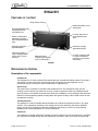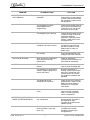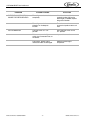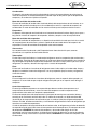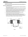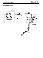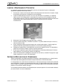
1
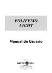
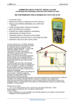
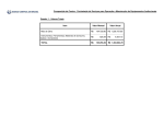
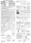
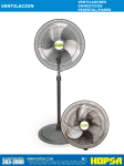
®
BOTTLE COOLERS
COR9530UBCST
Service Manual
Release Date: May, 2004
Publication Number: 630460279SER
Revision Date: NA
Revision: A
Visit the IMI Cornelius web site at www.cornelius.com for all your Literature needs.
SERVICE MANUAL
The products, technical information, and instructions contained in this manual are subject
to change without notice. These instructions are not intended to cover all details or variations of the equipment, nor to provide for every possible contingency in the installation,
operation or maintenance of this equipment. This manual assumes that the person(s)
working on the equipment have been trained and are skilled in working with electrical,
plumbing, pneumatic, and mechanical equipment. It is assumed that appropriate safety
precautions are taken and that all local safety and construction requirements are being
met, in addition to the information contained in this manual.
To inquire about current revisions of this and other documentation or for assistance with
any Cornelius product contact:
www.cornelius.com
800-238-3600
Trademarks and copyrights:
Aurora, Cornelius, Decade, Hydro Boost, Sitco, Spirit, UF-1, Vanguard, Venture, Olympus,
and Vista are registered trademarks of IMI Cornelius Inc.
Optifill trademark is pending.
This document contains proprietary information and it may not be
reproduced in any way without permission from Cornelius.
Printed in U.S.A.
Copyright © 2004, All Rights Reserved, IMI Cornelius, Inc.
COR9530UBCST Service Manual
TABLE OF CONTENTS
Table of Contents . . . . . . . . . . . . . . . . . . . . . . . . . . . . . . . . . . . . . . . . . . . . . . . . . . . . . . i
English . . . . . . . . . . . . . . . . . . . . . . . . . . . . . . . . . . . . . . . . . . . . . . . . . . . . . . . . . . . . . .
Features of the Unit . . . . . . . . . . . . . . . . . . . . . . . . . . . . . . . . . . . . . . . . . . . . . . . . .
Refrigeration System . . . . . . . . . . . . . . . . . . . . . . . . . . . . . . . . . . . . . . . . . . . . . . . . .
Description of its components . . . . . . . . . . . . . . . . . . . . . . . . . . . . . . . . . . . . . . .
The Refrigeration Cycle . . . . . . . . . . . . . . . . . . . . . . . . . . . . . . . . . . . . . . . . . . . . . .
Electrical Wiring . . . . . . . . . . . . . . . . . . . . . . . . . . . . . . . . . . . . . . . . . . . . . . . . . . . .
Cleaning and Preventive Maintenance . . . . . . . . . . . . . . . . . . . . . . . . . . . . . . . . . . .
Condensate Disposal System . . . . . . . . . . . . . . . . . . . . . . . . . . . . . . . . . . . . . . . . . .
Troubleshooting . . . . . . . . . . . . . . . . . . . . . . . . . . . . . . . . . . . . . . . . . . . . . . . . . . . .
Possible causes and solutions . . . . . . . . . . . . . . . . . . . . . . . . . . . . . . . . . . . . . .
1
1
1
1
2
4
5
5
6
6
Español . . . . . . . . . . . . . . . . . . . . . . . . . . . . . . . . . . . . . . . . . . . . . . . . . . . . . . . . . . . . . 9
Caracteristicas del equipo . . . . . . . . . . . . . . . . . . . . . . . . . . . . . . . . . . . . . . . . . . . . . 9
Sistema de Refrigeracion . . . . . . . . . . . . . . . . . . . . . . . . . . . . . . . . . . . . . . . . . . . . . 9
Explicación de los componentes . . . . . . . . . . . . . . . . . . . . . . . . . . . . . . . . . . . . . 9
El Ciclo de Refrigeracion . . . . . . . . . . . . . . . . . . . . . . . . . . . . . . . . . . . . . . . . . . . . . 11
Diagrama eléctrico . . . . . . . . . . . . . . . . . . . . . . . . . . . . . . . . . . . . . . . . . . . . . . . . . 12
Limpieza y Mantenimiento Preventivo . . . . . . . . . . . . . . . . . . . . . . . . . . . . . . . . . . 13
Sistema de Recolección de Condensado . . . . . . . . . . . . . . . . . . . . . . . . . . . . . . . . 13
Principales Problemas del Refrigerador . . . . . . . . . . . . . . . . . . . . . . . . . . . . . . . . . 14
Posibles causas y soluciones . . . . . . . . . . . . . . . . . . . . . . . . . . . . . . . . . . . . . . 14
© 2004, IMI Cornelius Inc.
-i-
Publication Number: 630460279SER
COR9530UBCST Service Manual
Publication Number: 630460279SER
- ii -
© 2004, IMI Cornelius Inc.
COR9530UBCST Service Manual
ENGLISH
FEATURES OF THE UNIT
Sturdy, stainless steel top
Rubber pull handle for easy
sliding of lids
Strong body with thick walls,
injected with CFC-free
polyurethane foam
Forced-air evaporator for
quick temperature pulldown
Exterior cabinet made of
galvanized, pre-painted
steel, with baked polyester
paint
Reinforced, heavy-duty,
adjustable dividers
Interior lining made of
acrylic-coated galvanized
steel for extra corrosion
resistance
Reinforced, 16 gauge
galvanized steel base
Heavy-duty R-134a
condensing unit with easy
access for maintenance
Forced-air condenser made
of copper and aluminum,
resistant to rust and saline
environments
FIGURE 1
REFRIGERATION SYSTEM
Description of its components
Compressor:
The compressor is a factory-sealed unit located underneath (outside) the cooling cabinet. This pump is
activated by a motor which draws low-pressure vapor (refrigerant) from the evaporator. It then
compresses the gas and forces it into the condenser at a high pressure.
Starter relay:
The starter relay is attached on one side of the compressor box. The compressor motor has two
windings: one for starting and another for running. In order to provide for necessary additional torque
when the motor is first ignited, the starter relay connects the additional start-up windings. After the motor
reaches its correct operating speed, the relay opens the ignition windings and the motor carries on with
the operation windings.
Thermal protector:
This protector is a thermo-sensible device attached to one side of the compressor’s box. In any given
situation, if the compressor overheats or the voltage source varies drastically, the thermal protector
opens, turning off the compressor. After the compressor cools down to a normal and safe working
temperature, the thermal protector turns on the compressor.
Condenser:
The condenser is located underneath (outside) the cooling cabinet in front of the compressor. It receives
hot, high-pressure refrigerant gas from the compressor and cools it down until it returns to liquid state.
© 2004, IMI Cornelius Inc.
-1-
Publication Number: 630460279SER
COR9530UBCST Service Manual
Condenser fan motor:
The condenser fan motor is located underneath the cooling cabinet. It is a ventilation device which forces
the ambient air to flow over the condenser in order to cool down the refrigerant flowing inside it. The fan
motor works only if the compressor is on.
Evaporator:
The evaporator is located inside the cooling cabinet. As the gas flows at a low pressure through the
evaporator, it absorbs heat through the copper coil from inside the cabinet.
Evaporator fan motor:
This device provides the required circulation of air through the cooling cabinet as well as over the surface
of the evaporator’s serpentine thermal exchange area. This fan motor runs continuously.
The evaporator and condenser serpentines have aluminum fins that help increase the surfaces for the
thermal exchange in an efficient way.
Capillary tube:
It consists of several feet of tubing having a small inside diameter. It is a device used to control the
amount of refrigerant that flows into the evaporator.
Drier:
The drier is located in between the condenser and the evaporator. It traps and removes moisture in the
refrigeration system while allowing oil and refrigerant to flow freely.
Accumulator:
The accumulator is located in between the evaporator and the compressor. It is a storage tank which
receives refrigerant liquid from the evaporator and prevents it from flowing into the compressor.
Temperature control:
The adjustable temperature control is responsible for detecting temperature changes inside the cooling
cabinet. It also starts the compressor motor whenever the cabinet rises above the desired temperature.
The temperature control consists of a switch which is mechanically activated by a diaphragm. This
diaphragm is connected to a thermo-sensible bulb (located inside the cabinet) through a small diameter
tube. All three components (the diaphragm, the thermo-sensible bulb, and the small diameter tube) are
filled with refrigerant gas which reacts to temperature changes.
When the cabinet temperature rises, the refrigerant in the bulb heats up and expands, expanding the
diaphragm. The diaphragm’s expanding closes the temperature control’s interrupting device and then
starts the compressor and condenser motors.
The drop in temperature inside the cooling compartment is caused by the refrigerant’s continuous
circulation through the system. When the temperature drops, the refrigerant inside the temperature
control’s bulb contracts, allowing the diaphragm to open the interrupting device, which consequently
shuts down the compressor and condenser motors.
Cooling cabinet:
This is the area where the goods are stored. It has been designed to allow for constant cold air circulation
to flow through the goods.
THE REFRIGERATION CYCLE
1.
2.
3.
Depending on the increase in temperature inside the cooling compartment, the refrigerant gas
inside the temperature control's bulb heats up and expands, expanding the diaphragm. The
diaphragm's expansion closes the temperature control's interrupting device.
The temperature control's interrupting device turns on the compressor and condenser motors.
The compressor recirculates the refrigerant throughout the system by drawing the refrigerant gas
as low vapor pressure from the evaporator. Then it compresses the refrigerant and forces it into the
condenser.
Publication Number: 630460279SER
-2-
© 2004, IMI Cornelius Inc.
COR9530UBCST Service Manual
4.
5.
6.
7.
The condenser, with the help of its fan motor, removes the refrigerant's heat as it flows through the
condenser. The heat is then released to the outside environment. Consequently, the decrease in
temperature will change the refrigerant from a gaseous to a liquid state.
The capillary tube regulates the amount of refrigerant that is discharged into the evaporator.
The evaporator's serpentine allows the refrigerant to absorb and remove heat from the cooling
compartment.
The drop in temperature inside the cooling compartment is caused by the refrigerant's continuous
circulation through the system. This gas continuously absorbs the heat that exists inside the cooling
compartment and expels it to the outside environment. When the temperature drops, the refrigerant
inside the temperature control's bulb contracts, allowing the diaphragm to open the interrupting
device, which consequently shuts down the compressor and condenser motors.
FIGURE 2
© 2004, IMI Cornelius Inc.
-3-
Publication Number: 630460279SER
COR9530UBCST Service Manual
ELECTRICAL WIRING
FIGURE 3
Publication Number: 630460279SER
-4-
© 2004, IMI Cornelius Inc.
COR9530UBCST Service Manual
CLEANING AND PREVENTIVE MAINTENANCE
Proper maintenance of your refrigerator is most important for efficient operation and economical
performance.
1.
2.
Disconnect the power source before cleaning, remove all products, and place them in another
cooler.
Clean the condenser at least once a month with a vacuum cleaner or brush. If the condenser coil
has accumulated dirt and grease (possible in heavy traffic areas or kitchen), use a strong cleaning
solution. If you find any oil in the condensing unit compartment, call a qualified service person
immediately.
FIGURE 4
3.
4.
5.
6.
7.
8.
Keep the floor area around the fixture clean and orderly.
Check the door operation and door seal. Doors much close by themselves and seal on all sides.
Empty the drain pan located underneath the condensing unit at the rear and clean it as required.
Check it regularly for excessive water accumulation.
Replace any malfunctioning parts as soon as possible. Ask your dealer or service agency to order
the parts required.
It is most important that the interior of the fixture be cleaned on a periodic basis. Remove the
product load and all shelving.
Use only mild soap or detergent to wash the interior and exterior. Rinse with warm, clean water and
dry with a soft absorbent cloth.
CONDENSATE DISPOSAL SYSTEM
Refrigerators come equipped with an interior bottom floor drain that exits the cabinet at the motor
compartment side.
Beverage Coolers with Forced Air refrigeration system have a drain that collects the condensate from the
evaporator inside the baffle to a non-electric evaporating pan located in the bottom of the cabinet next to
the condensing unit. No additional plumbing installation is required. This pan should be checked
periodically for excessive accumulation of water.
An electric evaporator pan is available as an optional accessory. For additional information, please
contact our distributors.
© 2004, IMI Cornelius Inc.
-5-
Publication Number: 630460279SER
COR9530UBCST Service Manual
TROUBLESHOOTING
Possible causes and solutions
PROBLEM
COMPRESSOR WILL NOT
START
THE TEMPERATURE IS TOO
COLD
THE TEMPERATURE IS NOT
COLD ENOUGH
Publication Number: 630460279SER
POSSIBLE CAUSE
SOLUTION
No voltage in the electrical
socket.
Use a voltmeter to check the
voltage.
The electrical conductor or
wires may be cut.
Use an ohmmeter to check for
continuity.
Defective electrical
components such as:
thermostat, relay, thermal
protector, etc.
Replace defective components.
Thermostat in “off” position.
Turn the thermostat’s knob to
its maximum position and wait
to see if the compressor starts.
Compressor motor has a
winding open or shorted.
Measure the ohmic resistance
of the main and auxiliary
windings using an ohmmeter.
Compare them with the correct
values.
Dirty condenser; lack of air
flow.
Clean condenser and allow for
air circulation.
Low voltage.
Use a voltage regulator if the
voltage is lower than 103 volts.
Compressor is stuck.
Change the compressor.
Thermostat knob is set at a
very cold position.
Set the thermostat knob to a
warmer position and check if
the compressor stops
according to the thermostat’s
operating range.
Thermostat does not
disconnect the condensing unit.
Check the insulation of the
thermostat. If the problem
persists, change the
thermostat.
Thermostat capillary bulb is
loose or installed improperly.
Correctly fasten the thermostat
capillary bulb.
Thermostat knob is set at a
very warm position.
Set the thermostat knob to a
colder position.
Condenser is dirty; lack of air
flow.
Clean the condenser and allow
for air circulation.
The refrigerator has been
placed at an inadequate
location.
The unit must not be near
stoves, walls that are exposed
to the sun, or places that lack
sufficient air flow.
-6-
© 2004, IMI Cornelius Inc.
COR9530UBCST Service Manual
PROBLEM
POSSIBLE CAUSE
SOLUTION
The refrigerator has been used
improperly.
The shelves must never be
covered with any type of plastic
or other material that will block
the circulation of cold air within
the refrigerator.
The refrigerator has been
overcharged with the
refrigerant gas.
Check to see if condensation or
ice crystals have formed on the
suction line. If so, charge with
the correct amount of gas.
The refrigerant gas is leaking.
Find the location where the gas
is leaking in order to seal it or
replace the defective
component. Change the drier.
Perform a good vacuum and
recharge the unit.
The evaporator and/or
condenser fans aren’t working.
Check the electrical
connections and make sure
that the fan blade isn’t stuck.
Replace the fan motor if it
doesn’t work.
Low voltage.
Use a voltage regulator if the
voltage is lower than 103 volts.
ELECTRICAL SHOCKS
Wires or electrical components
are in direct contact with
metallic parts.
Check for appropriate
insulation on the connections of
each electrical component.
NOISE
The refrigerator is not properly
leveled.
Check if the noise goes away
after you level the refrigerator.
The condenser is not fastened
correctly. Copper tubings are in
contact with metal.
While the compressor is
working, check to see if metal
parts are in contact with one
another and/or if the screws
that fasten the condenser are
tightened.
The evaporator and/or
condenser fans are loose.
Check if the fans are securely
fastened. Also, check if the fan
blades are loose, broken or
crooked. If so, change the
faulty blade.
Compressor has an internal
noise.
If the noise persists after all
other measures have been
taken, it may be originating
from the compressor.
Thermostat knob is set at a
very cold position.
Set the thermostat knob to a
warmer position and check if
the compressor stops
according to the thermostat’s
operating range.
The outside environment’s
relative humidity is very high
(over 75%).
This type of occurrence is
caused by local climatic
conditions and not by the
refrigerated unit.
THE TEMPERATURE IS NOT
COLD ENOUGH
EXTREME CONDENSATION
INSIDE THE REFRIGERATOR
© 2004, IMI Cornelius Inc.
-7-
Publication Number: 630460279SER
COR9530UBCST Service Manual
PROBLEM
POSSIBLE CAUSE
SOLUTION
EXTREME CONDENSATION
INSIDE THE REFRIGERATOR
The refrigerator door won’t shut
completely.
Check the door and/or the
magnetic gasket. Adjust the
door hinges if needed; replace
the gasket if broken.
The refrigerator has been
placed at an inadequate
location.
The unit must not be near
sources that produce too much
heat.
The light switch is in “off”
position.
Press the light switch to the
“on” position.
False contact on the light
switch, the fluorescent tube, or
the ballast.
Inspect all connections.
Light switch, ballast and/or
fluorescent tube are damaged.
Replace the damaged
component.
NO ILLUMINATION
Publication Number: 630460279SER
-8-
© 2004, IMI Cornelius Inc.
COR9530UBCST Service Manual
ESPAÑOL
CARACTERISTICAS DEL EQUIPO
Tapas, tope y tope para vasos
robustos, en acero inoxidable
Tirador de goma para
facilitar el deslizamiento de
las tapas
Paredes gruesas y fuertes,
inyectadas con aislante de
poliuretano libre de CFC’s
Gabinete exterior de lámina
galvanizada, prepintada con
pintura de poliéster al horno
Evaporador de aire forzado
para un rápido “pull-down”
Divisores adjustables
“heavy-duty” reforzados
Paredes interiores en acero
galvanizado con recubrimiento
acrílico para mayor resistencia
a la corrosión
Base reforzada con lámina
galvanizada calibre 16
Unidad condensadora “heavyduty” para R-134a de fácil
acceso para el servicio
Condensador de aire
forzado en cobre y aluminio,
resistente a la oxidación y el
ambiente salino
FIGURE 5
SISTEMA DE REFRIGERACION
Explicación de los componentes
Compresor:
El compresor es una unidad herméticamente sellada localizada debajo (afuera) del compartimiento de
enfriamiento. El compresor es una bomba accionada por un motor, que extrae vapor de baja presión
(refrigerante) del serpentín del evaporador, lo comprime y lo fuerza dentro del condensador a alta
presión.
Rele de arranque:
El relé de arranque está montado en el costado de la caja del compresor. El motor del compresor tiene
dos devanados, un devanado de arranque y devanado de marcha. Para poder darle al motor fuerza
torsional adicional cuando primero arranca, el relé de arranque conecta el devanado de arranque
adicional. Después que el motor llega a la velocidad correcta el relay abre el devanado de arranque y el
motor continua con el devanado de marcha.
Protector termico:
El protector térmico es un dispositivo termosensible montado en el costado de la caja del compresor. Si
el motor del compresor se pone demasiado caliente o toma una cantidad excesiva de corriente, el
protector térmico se abrirá, rompiendo los circuitos de arranque y de marcha del motor. Después que el
compresor se enfríe a una temperatura operacional segura, el protector térmico cerrará permitiendo que
el motor del compresor vuelva a arrancar.
© 2004, IMI Cornelius Inc.
-9-
Publication Number: 630460279SER
COR9530UBCST Service Manual
Condensador:
El serpentín del condensador está localizado debajo (afuera) del compartimiento de enfriamiento al
frente del compresor. El condensador desplaza calor del vapor de alta presión que se desprende del
compresor y lo condensa en líquido a alta presión.
Motor del ventilador del condensador:
El motor del ventilador del condensador, localizado debajo del compartimiento de enfriamiento, es un
dispositivo de ventilación forzada que usa aire ambiente para enfriar la superficie del serpentín del
condensador. El motor del ventilador está en marcha mientras que el compresor está en marcha.
Evaporador:
El serpentín del evaporador está localizado en el compartimiento de enfriamiento. Según pasa vapor a
baja presión a través del serpentín del evaporador, absorbe y desplaza calor del compartimiento.
Motor del ventilador del evaporador:
El motor del ventilador del evaporador es un dispositivo de ventilación forzada que circula aire a través
del compartimiento de enfriamiento y sobre la superficie de intercambio térmico del serpentín del
evaporador. El motor del ventilador del evaporador corre continuamente.
Observacion:
Los serpentines del Condensador y del Evaporador tienen aletas de aluminio para aumentar
eficazmente sus superficies de intercambio térmico.
Tubo capilar:
El tubo capilar está localizado en el conducto del refrigerante, entre los serpentines del condensador y
del evaporador. Este tubo de diámetro pequeño es usado como dispositivo de medición para controlar el
flujo de refrigerante líquido del serpentín del evaporador. Esto crea una baja presión que causa que el
refrigerante se vaporice y absorba calor según pasa a través del evaporador.
Filtro:
El filtro está localizado en el conducto del refrigerante entre el tubo capilar y el condensador. Atrapa y
desplaza humedad del sistema de refrigeración a la vez que permite que pase aceite y refrigerante a
través del sistema.
Acumulador:
El acumulador está localizado en el conducto del refrigerante, entre el serpentín del evaporador y el
compresor. El acumulador atrapa cualquier refrigerante líquido que no se vaporizó antes de llegar al
compresor.
Control de temperatura:
El control ajustable de temperatura es responsable por detectar cambios de temperatura en el
compartimiento de enfriamiento y arranca el motor del compresor cuando la temperatura del
compartimiento sube sobre una temperatura preestablecida.
El control de temperatura está compuesto de un interruptor de control que es accionado (abierto y
cerrado) por el movimiento mecánico del fuelle. El fuelle está conectado a un bulbo termosensible
(localizado en el compartimiento de enfriamiento) por un conducto (tubo) de refrigerante de pequeño
diámetro. El fuelle, el bulbo termosensible, y el conducto de refrigerante están llenos de refrigerante que
reaccionan a cambios de temperaturas.
Cuando la temperatura del compartimiento de enfriamiento sube, el refrigerante en el bulbo de detección
se expande forzando que el fuelle cierre el interruptor de control de temperatura. El interruptor de control
de temperatura ENCIENDE los motores del compresor y del condensador. Según el ciclo de
refrigeración enfría el compartimiento, el refrigerante en el bulbo de detección se contrae permitiendo
que el fuelle se relaje, accionando a su posición abierta, APAGANDO los motores del compresor y del
condensador.
Publication Number: 630460279SER
- 10 -
© 2004, IMI Cornelius Inc.
COR9530UBCST Service Manual
Compartimiento de enfriamiento:
El compartimiento de enfriamiento es el área del refrigerador donde se mantiene el producto para
entrega. Esta área está diseñada para permitir que circule un continuo flujo de aire a través del producto.
EL CICLO DE REFRIGERACION
1.
2.
3.
4.
5.
6.
7.
Según sube la temperatura en el compartimiento de enfriamiento, el refrigerante en el bulbo del
control de tempretura se calienta y expande, expandiendo el fuelle. La expansión del fuelle cierra el
interruptor de control de temperatura.
El interruptor de control de temperatura ENCIENDE los motores del compresor y del condesador.
El compresor circula refrigerante a través del sistema extrayendo vapor refrigerante a baja presión
del serpentín del evaporador, comprimiéndolo y forzándolo en el serpentín del condensador.
El condensador, ayudado por el motor del ventilador del condensador, desplaza calor del
refrigerante según fluye a través del serpentín del condensador y lo libera al ambiente exterior. La
caída de la temperatura del refrigerante cambia el vapor a líquido.
El tubo capilar controla la cantidad de refrigerante liberado al serpentín del evaporador.
El serpentín del evaporador permite que el refrigerante absorba y desplace calor del
compartimiento de enfriamiento según fluye a través del serpentín.
La caída de temperatura en el compartimiento de enfriamiento es causada por la circulación
continua de refrigerante a través del sistema, desplazando calor del compartimiento de
enfriamiento y transportándolo al ambiente exterior. Cuando la temperatura baja, el refrigerante en
el bulbo del control de temperatura se contrae, permitiendo que el fuelle aba el interruptor de
control de temperatura, apagando los motores del compresor y del condensador.
FIGURE 6
© 2004, IMI Cornelius Inc.
- 11 -
Publication Number: 630460279SER
COR9530UBCST Service Manual
DIAGRAMA ELÉCTRICO
FIGURE 7
Publication Number: 630460279SER
- 12 -
© 2004, IMI Cornelius Inc.
COR9530UBCST Service Manual
LIMPIEZA Y MANTENIMIENTO PREVENTIVO
Un apropiado mantenimiento de su refrigerador es de muy alta importancia para un desempeño
económico y operación eficiente del mismo.
1.
2.
Desconecte la fuente de alimentación eléctrica del refrigerador antes de realizar la limpieza. Saque
los productos que contenga y colóquelos en otro refrigerador.
Limpie el condensador por lo menos una vez al mes utilizando una aspiradora o un cepillo de
cerdas suaves. Si el condensador ha acumulado sucio y grasa (lo cual es posible en áreas de
mucho tráfico o cocinas), utilice una solución limpiadora fuerte. Si encuentra rastros de aceite en el
compartimiento de la unidad condensadora, llame a un técnico de servicio calificado
inmediatamente.
FIGURE 8
3.
4.
5.
6.
7.
8.
Mantenga el área alrededor del refrigerador limpia y ordenada.
Revise la correcta operación y sellado de las puertas. Las puertas deben cerrar por sí mismas y
sellar en todos los lados.
Vacíe la bandeja de drenaje localizada detrás de la unidad condensadora y límpiela según sea
requerido. Revísela regularmente para prevenir una acumulación excesiva de agua.
Reemplace cualquier pieza o parte defectuosa tan pronto sea posible. Diríjase a su distribuidor o
agencia de servicio para ordenar las piezas o partes requeridas.
Es de mucha importancia que el interior del refrigerador sea limpiado periódicamente. Remueva
todo el producto y las parrillas para realizar esta operación.
Utilice únicamente jabón o detergente suaves para lavar el interior y el exterior. Enjuague con agua
limpia y séquelo con un paño suave absorbente.
SISTEMA DE RECOLECCIÓN DE CONDENSADO
Algunos refrigeradores (enfriadores de botellas horizontales) vienen equipados con un drenaje interior
en el fondo que sale del gabinete del lado del compartimiento de la unidad condensadora.
Los refrigeradores con sistema de aire forzado tienen un drenaje que recoge la condensación producida
por el evaporador y la dirige a una bandeja localizada junto a la unidad condensadora. No es necesario
realizar ninguna instalación de plomería adicional. Esta bandeja debe ser revisada periódicamente para
prevenir una acumulación excesiva de agua.
Una bandeja evaporadora eléctrica está disponible como accesorio opcional. Para información adicional,
por favor contacte a nuestros distribuidores.
© 2004, IMI Cornelius Inc.
- 13 -
Publication Number: 630460279SER
COR9530UBCST Service Manual
PRINCIPALES PROBLEMAS DEL REFRIGERADOR
Posibles causas y soluciones
PROBLEMA
COMPRESOR NO ARRANCA
DEMASIADO FRIO
Publication Number: 630460279SER
POSIBLE CAUSA
SOLUCION
NO HAY VOLTAJE EN LA
TOMA DE ALIMENTACION
VERIFIQUE CON UN
VOLTIMETRO
CONDUCTO ELECTRICO O
ALAMBRES CORTADOS
UTILIZANDO UN
OHMIMETRO, VERIFIQUE SI
EXISTE CONTINUIDAD EN EL
CONDUCTOR ELECTRICO O
ALAMBRE
FALLA EN LOS
COMPONENTES
ELECTRICOS TALES COMO:
TERMOSTATO, PROTECTOR
TERMICO
REEMPLAZAR EL
COMPONENTE
DEFECTUOSO
TERMOSTATO EN POSICION
"OFF"
FIJE LA POSICION DE LA
PERILLA DEL TERMOSTATO
EN FRIO MAXIMO Y
OBSERVE SI EL
COMPRESOR ARRANCA
BOBINAS DEL MOTOR DE
COMPRESOR CORTADAS O
QUEMADAS
MIDA LA RESISTENCIA
OHMICA DE LAS BOBINAS
PRINCIPAL Y AUXILIAR
UTILIZANDO UN
OHMIMETRO Y
COMPARELAS CON LOS
VALORES CORRECTOS
CONDENSADOR SUCIO,
FALTA CIRCULACION DE
AIRE
LIMPIE EL CONDENSADOR Y
PERMITA LA CIRCULACION
DE AIRE
BAJO VOLTAJE
PARA ELIMINAR EL
PROBLEMA DE VOLTAJE
MENOR QUE 103 VOLTS, ES
RECOMENDABLE EL USO DE
UN REGULADOR DE
VOLTAJE
COMPRESOR TRANCADO
REEMPLACE EL
COMPRESOR
TERMOSTATO FIJADO EN
POSICION MUY FRIA
FIJE LA PERILLA DEL
TERMOSTATO A UNA
POSICION MAS CALIENTE Y
VERIFIQUE SI EL
COMPRESOR PARA
DENTRO DEL RANGO DE
OPERACION DEL
TERMOSTATO
TERMOSTATO NO
DESCONECTA LA UNIDAD
CONDENSADORA
VERIFIQUE LA FIJACION DEL
BULBO DEL TERMOSTATO,
SI EL PROBLEMA
CONTINUA, CAMBIE EL
TERMOSTATO
- 14 -
© 2004, IMI Cornelius Inc.
COR9530UBCST Service Manual
PROBLEMA
POSIBLE CAUSA
SOLUCION
DEMASIADO FRIO
BULBO DEL TERMOSTATO
DESPRENDIDO O MAL
FIJADO
FIJE CORRECTAMENTE EL
BULBO DEL TERMOSTATO
POCO FRIO
TERMOSTATO FIJADO EN
POSICION MUY CALIENTE
FIJE LA POSICION DEL
TERMOSTATO A UNA
POSICION MAS FRIA
CONDENSADOR SUCIO,
FALTA DE CIRCULACION
DEL AIRE
LIMPIE EL CONDENSADOR Y
PERMITA LA CIRCULACION
DEL AIRE
EL REFRIGERADOR ESTA
MAL UBICADO
EL REFRIGERADOR NO
DEBE DE ESTAR CERCA DE
COCINAS, PAREDES
EXPUESTAS AL SOL,
LUGARES SIN CIRCULACION
DE AIRE O MUY SOLEADOS
EL REFRIGERADOR ES MAL
UTILIZADO
LAS PARRILLAS NO DEBEN
DE CUBRIRSE CON NINGUN
PLASTICO O MATERIAL QUE
OBSTRUYA LA
CIRCULACION DEL AIRE
DENTRO DEL
REFRIGERADOR
REFRIGERADOR CON
SOBRECARGA DE GAS
VERIFIQUE SI EXISTE
CONDENSACION O
FORMACION DE ESCARCHA
EN LA LINEA DE SUCCION.
SI EXISTE, CARGUE
CORRECTAMENTE
FALTA DE GAS
REFRIGERANTE
CARGUE CORRECTAMENTE
EXISTENCIA DE UNA FUGA
DE GAS REFRIGERANTE
VERIFIQUE EL PUNTO
DONDE SE ENCUENTRA LA
FUGA PARA ELIMINARLA O
REEMPLAZAR EL
COMPONENTE. CAMBIE EL
FILTRO DESHIDRATADOR,
EFECTUE VACIO Y
COLOQUE NUEVA CARGA
DE GAS
VENTILADOR DEL
EVAPORADOR O DE UNIDAD
CONDENSADORA NO
FUNCIONA
VERIFIQUE CONEXIONES
ELECTRICAS Y QUE EL
ASPA NO ESTE TRABADA.
REEMPLACE EL
COMPONENTE CUANDO EL
MOTOR ESTE QUEMADO
BAJO VOLTAJE
PARA ELIMINAR EL
PROBLEMA DE VOL-TAJE
MENOR QUE 103 VOLTS. ES
RECO-MENDADO EL USO DE
UN REGULADOR DE
VOLTAJE
© 2004, IMI Cornelius Inc.
- 15 -
Publication Number: 630460279SER
COR9530UBCST Service Manual
PROBLEMA
CHOQUE ELECTRICO
RUIDO
CONDENSACION EXTREMA
EN EL REFRIGERADOR
Publication Number: 630460279SER
POSIBLE CAUSA
SOLUCION
ALAMBRES O DISPOSITIVOS
ELECTRICOS EN CONTACTO
CON PARTES METALICAS
VERIFIQUE SI HAY FALLA EN
EL AISLA-MIENTO DE UN
COMPONENTE ELECTRICO
QUE ESTE EN CONTACTO
CON PARTES METALICAS.
AISLE CORRECTAMENTE.
COMPRESOR CON PASO DE
CORRIENTE A LA CARCAZA
VERIFIQUE CONTINUIDAD
CONECTANDO LOS
TERMINALES DE UNA
LAMPARA DE PRUEBA
ENTRE EL BORDE COMUN Y
EL TERMINAL DE TIERRA
DEL COMPRESOR. SI LA
LAMPARA ENCIENDE,
REEMPLACE EL
COMPRESOR
MALA NIVELACION DEL
REFRIGERADOR
VERIFIQUE SI EL RUIDO SE
ELIMINA CUANDO EL
REFRIGERADOR ESTA
NIVELADO
CONDENSADOR MAL
FIJADO. TUBERIAS EN
CONTACTO CON METAL
TENIENDO EL COMPRESOR
FUNCIONANDO. VERIFIQUE
SI PARTES METALICAS
ESTAN EN CONTACTO Y/O
QUE LOS TORNILLOS DE
SUJECCION DEL
CONDENSSADOR ESTEN
DEBIDAMENTE APRETADOS
ABANICO DEL
EVAPORADOR O DE UNIDAD
CONDENSADORA FLOJO
VERIFIQUE SI LOS
ABANICOS ESTAN BIEN
FIJADOS. VERIFIQUE SI EL
ASPA DEL ABANISCO ESTA
FLOJA, QUEBRADA O
TORCIDA CREANDO UNA
EXCESIVA VIBRACION.
CAMBIE EL ASPA.
COMPRESOR CON RUIDO
INTERNO
SI DESPUES DE ANALIZAR
TODOS LOS ASPECTOS
PREVIAMENTE DESCRITOS,
EL RUIDO PERSISTE, SU
ORIGEN PUEDE ESTAR EN
EL COMPRESOR
TERMOSTATO FIJADO EN
POSICION DEMASIADO FRIA
FIJE LA PERILLA DEL
TERMOSTATO EN UNA
POSICION MAS CALIENTE.
VERIFQUE QUE EL
COMPRESOR PARE
DENTRO DEL RANGO DE
OPERACION DEL
TERMOSTATO
HUMEDAD REALTIVA DEL
AIRE ES MUY ALTA (ARRIBA
DEL 75%)
ESTA CLASE DE DAÑO ES
CAUSADO POR LAS
CONDICIONES
CLIMATOLOGICAS LOCALES
Y NO POR EL
REFRIGERADOR
- 16 -
© 2004, IMI Cornelius Inc.
COR9530UBCST Service Manual
PROBLEMA
CONDENSACION EXTREMA
EN EL REFRIGERADOR
LAMPARA NO ENCIENDE
© 2004, IMI Cornelius Inc.
POSIBLE CAUSA
SOLUCION
PUERTA DEL
REFRIGERADOR NO SELLA
VERIFIQUE SI LA PUERTA
ESTA MAL AJUSTADA O SI
EL EMPAQUE ESTA ROTO.
AJUSTE LA PUERTA O
REEMPLACE EL EMPAQUE
EL REFRIGERADOR ESTA
MAL UBICADO
EL REFRIGERADOR NO
DEBE DE ESTAR UBICADO
CERCA DE FUENTES DE
CALOR
SWITCH EN POSICION "OFF"
COLOQUE EL SWITCH EN
POSICION "ON"
FALSO CONTACTO EN EL
SWITCH, CONECTORES DEL
TUBO FLUORESCENTE O
BALASTRO
REVISE CONEXIONES
SWITCH , BALASTRO Y/O
TUBO FLOURESCENTE
DEFESTUOSO
REEMPLACE COMPONENTE
DEFECTUOSO
- 17 -
Publication Number: 630460279SER
COR9530UBCST Service Manual
Publication Number: 630460279SER
- 18 -
© 2004, IMI Cornelius Inc.