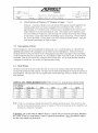
1
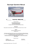
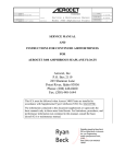
/1EROCET
ISSUE
DATE,
I
N••, . ,
TITLE:
REVISION"'
DATE:
!
PitGE
Incorporated
7/22/05
----'---
SUBTITLE,
Service & Maintenance Manual
Model 3500 or 3500L Floats
PTLE NO::.'
A-IOO32
R£VISION"
,~
..
SERVICE MANUAL
AND
INSTRUCTIONS FOR CONTINUED AIRWORTHINESS
FOR
AEROCET 3500, or 3500L SEAPLANE FLOATS
Aeroeet, Inc.
P.O. Box 2119
265 Shannon Lane
Priest River, Idaho 83856
Phone: (208) 448-0400
Fax: (208) 448-1644
of 12
1
-,---
",
• f
0
L1EROCET
ISSUE
DATE;
I
TITLE:
REVISION
I
SUBTITLE:
DATE-:
PAGS
Incorporated
7/22/05
Service & Maintenance Manual
Model 3500 or 3500L Floats
2 of 12
'·PIl.E :00.
A-IOO32
REI'ISIO~,
; .i,
,'!i'
0
LOG OF REVISIONS PAGE
REV.
PAGES
AFFECT.
ALL
0
I
DESCRIPTION
DATE
Initial Release
7/22/05
APPROVED
./" r-::-J /'
,
/l::r-
,r
AEROCET
---
ISSUE I
DATE:
.--
Incorporated
7/22/05
TITLE:
REVISION/
DATE:
SUBTITLE:
--
Service & Maintenance Manual
Model 3500 or 3500L Floats
PAGE
--
.I
3 of 12
FILE 'NO.
A-IOO32
REVISION
0
Table of Contents
Description
Introduction and General Float Information
Float Hull Maintenance
Float Handling and Jacking
Water Rudder Retraction and Steering System
Repairing Composite Float Hulls
Continued Airworthiness Service Schedule, General Practices and Product
Listings for Service
Section
1
2
3
4
5
6
-
AEROCET
.
ISSUE
I
DATE:
~-~
. -
!--
REVISION r
DATE:
Incorporated
7/22/05
TITLE:
SUBTITLE:
Service & Maintenance Manual
Model 3500 or 3500L Floats
PA?t .1
FILENO,
A-IOO32
REVISION
..
-
--
4 of 12
0
SECTION 1. Introduction and General Float Information
This service and maintenance manual is applicable to Aerocet Model 3500 or 3500L Twin Seaplane
Floats and their general application to a variety of airplanes. Strut geometry, boxing (flying) wires, water
ludder retract routing are unique for each STC or TC application to aircraft. Installation of the Aerocet
Model 3500 or 3500L Twin Seaplane Floats should be done according to the FAA approved drawings
supporting these different applications.
The Aerocet Model 3500 or 3500L Twin Seaplane Floats are all composite float hulls separated by
spreader bars and are mounted to various airplanes with aerodynamic aluminum struts. These are rigidly
mounted. Boxing (flying) wires are used to stabilize the mounting of the floats to the airplane. The float
design utilizes a double-fluted bottom contour from the step forward and has a flat top deck design with
built-in antiskid. Water rudders are mounted on the stem of each float for water-taxi operations. Each
float offers a single large locker for storage, and six compartments for safety. Access to the insides of
these compartments is facilitated through access panels on the deck or through the storage locker hatch
cover.
The floats incorporate pump locations into each compartment which are used to remove any excess water
from condensation, leakage from the access panel gaskets, bolts, or pump-out plugs, or leakage from a
damaged float hull.
Steering of the airplane is done by the aircraft rudder at high taxi speeds or high RPM's while at slower
speeds the water rudders are deployed for effective maneuvering on the water.
SECTION 2. Float Hull Maintenance
Because of the composite structure in the design of the floats, hull corrosion and leakage are basically
eliminated. The floats should be kept clean with soap and water. The sides and the bottoms from the step
aft can be waxed to help in the cleaning process. The bottoms of the floats from the step forward should
not be waxed as this gives unpredictable water performance. Stains from the waterline on down may be
removed using marine fiberglass stain reIllover. We have used a product called FSR with good success.
Do not use abrasive cleaners or pads - these will scratch the white gel-coat surface. The gel-coat color
surface should always be maintained on the floats for ultraviolet protection.
The metal chine strips are abrasive wear surfaces used to protect the floats from docks and pilings. These
are extrusions bonded on using a one-part urethane adhesive. These should be kept intact.
The keels have UHMW plastic wear strips bonded on for protection and optional wear strips can be added
up from the keel in the step area where the float would nest in the rocks on the beach. These wear strips
should be observed on preflight or if you suspect damage. They should never be allowed to wear through
to the gel-coat surface on the float. Replace as necessary. (See Sec. 8 ,Fig. )
All float access panels are to be removed upon mmual inspection to view for hidden damage and to
comply with the maintenance and water rudder sections. During this time assure that all the pump-out
tubes are not cracked (especially around the fitting to the pump-out cup), that they pass through their
respective locators to keep them in the low spots, and have no blockages. If a pump-out tube is cracked,
,t1ERCCET
----rs~_ _ ~E:
7/_~
'-Rgy-rSrON
DATE:
I
Incorporated
TITLE:
SUBTITLE:
Service & Maintenance Manual
Model 3500 or 3500L Floats
PAGE
5 of 12
FILE 110."
A-IOO32
REVISION
0
SECTION 2. Float Hull Maintenance (cont'd)
it will not pull the water out of its respective compartment resulting in extra weight and CG problems.
Replace as necessary.
Any penetration to the float structure, delamination of the layers of cloth, or gel-coat wearing through
must be repaired according to hull repair Section 8. Significant damage warrants consultation from
Aerocet, Inc.
Winter storage, where temperatures may drop below freezing, is addressed by adding a quali ofRV
antifreeze through each of the pump-out cups. Taping over the pump-out holes will minimize the amount
of moisture that will enter each of the six compartments. Do not use masking tape.
Float locker latches and seals are to be maintained as needed. The locker latches are adjusted by spacing
the black catch ramp the correct distance to maintain an indent as the locker latches (the white dots to the
outside).
Investigation should be prompted if excessive water is pumped from any of the pump-out cups during
pre-flight. Water can leak through the pump-out plugs where the nylon pull line penetrates and may also
seep through the access panel seals. Condensation will also generate water inside the float compartments.
More than 4 or 5 full pumps of water, using an aircraft float pump, should raise concern for maintenance.
In contrast, if a pump-out tube is cracked or broken there will not be a significant sucking sound when the
pump is removed from the pump-out cup. If there is question regarding the integrity of the pump-out
tube, investigate. Attention should be given to any bolts that pass through the stern or other external float
structures. These should be sealed into place using a single part urethane such as Sikaflex 292. It should
also be noted that more water is typically pumped from the stem and bow compartments because they are
often covered with water during operation and allow more seepage through the plugs and seals. Pumpout plugs must have some venting capability to allow for expansion and contraction of the air in each
compartment during flight.
If the pilot, when on the water, runs over rocks or debris, he must assess the damage as sooli as possible.
Continuing into a high speed situation with the floats, will typically exaggerate the damage due to high
water pressure.
SECTION 3. Float Handling and Jacking
In order to service the landing gear parts and to do retraction tests, the floats are jacked up and blocked
using a floor jack with at least 1 ton capacity. Raise only one float at a time, chock the opposite float
properly and assure proper balance. The best lift point is 3 inches ahead of the step on the keel. This
locates the jack directly under the main bulkhead in the float. If space permits, use a board in between the
jack and the keel. After raising the float, block the float in a couple of places ahead of the step. Use a
sawhorse to support the after body of the float to keep the plane from tipping back. Locate the sawhorse
support under one of the back bulkheads which are located 17" & 45" forward from the stem.
During initial installation or for maintenance it may be convenient to use the lifting rings on the top of the
fuselage. These provide the proper points to attach a lifting harness to elevate the complete airplane. The
hoist should have a capacity of least 2 tons and a proper lifting harness to assure that the pull on the lift
rings is vertical.
The airplane may be otherwise lifted with either a launching dolly or large forklift under the spreader
bars. Care should be taken to lift as closely as possible to the float hulls without touching the hulls
,/lEROCET
-_..
ISSUE
DATE:
REVISION
DA.TE,
I
I
Incorporated
7/22/05
TITLE,
SUBTITLE:
Service & Maintenance Manual
Model 3500 or 3500L Floats
PAGE
6 of 12
r~~~No.'
REVISION
- .1,-10032
.
0
SECTION 4. Water Rudder Retraction and Steering System
4.1 General Description
The water rudders are used for steering when taxiing on the water. They are steered through 3/32"
stainless cables that connect to the airplanes rudder system and are retracted manually through a lever in
the cockpit again using 3/32" stainless cables, They should always be retracted before take-off and never
deployed until off the step. Damage may result if a take-off or landing is attempted with the rudders
down, Typically this damages the blade and the stainless tiller post. Internal sealed tubing in which the
3/32" cable passes through, prohibits water transfer between the two rear water tight compartments in
each float.
4.2 Rudder Assembly and Internal Cable Tubing - Reference 35-CPL-24001, Sheets 1-3 and
appropriate STC drawings.
1, Assemble and disassemble water rudders according to drawings. (See 35-24000 or 35-24001)
2,
Assure that water rudders are free in movement and rudder links and springs don't have excessive
wear.
3.
AllY hardware replaced that passes through the rear bulkhead should be sealed with a one part
urethane sealant.
4.
Regarding the internal cable tubing, look for any breaks or wear points (especially where the
retract cable comes out the inside of the float) and replace as necessary.
4.3 Rudder Pulleys - Reference 35-CPL-24001, Sheets 1-3.
1. Check freedom of pulleys in all locations. Remove and clean if there is any buildup in the
bushing to pulley interface.
2.
Remove any pulleys that have wear flats from lack of rotation,
4.4 Rudder Rigging - Reference 35-CPL-24001, Sheets 1-3 and appropriate STC drawings.
I . The rudder steering rigging should align the rudders straight ahead with the airplane rudder
centered. Cables should be just taught. There should be no pre-stretching of the springs, which
connect them to the airplane rudder system. This keeps the friction low, not hampering yaw
stability,
2. The rudder retract cables should be rigged so that the rudders are close to the stops when retracted
and that the cables are just becoming slack in the down position.
3,
All cables should be examined for deterioration especially around the pulleys at the stern of the
float.
/1EROCET
G--
ISSUE
DATE'.__
Incorpora ted
7 /22!..~
TITLE,
I
REVISION
DATE,
I
SUBTITLE:
Service & Maintenance Manual
Model 3500 or 3500L Floats
. pAGE
:
.~I;~~. ~~/
I
"I
R~4f~O~"'1
7 of 12
A-10032
0
SECTION 5. Repairing Composite Float Hulls
5.1.
General Description
Composite float repair, done correctly, will obtain the strength required to put the float back into service
and cosmetically show little or no evidence of damage ever taking place. The materials used for original
construction and repair, are conventional to the industry. Any damage on the bottom of the float should
be repaired immediately because of the tremendous water pressures encountered. Contact Aerocet, Inc.
prior to beginning a repair to obtain correct materials - resin (resins have shelf lives), catalyst, cloth, gelcoat, resin thickeners. Epoxy unde1water patch kits may be used in an emergency if the damage is
relatively small, but the repair must be replaced with correct materials for equal strength status. Damage
larger than 4" in size requires consulting Aerocet, Inc. for proper laminate orientation and assuring
number of laminates in the damaged area.
Repair Types and Procedures - All repaired areas on the exterior must be surface coated (gelcoated) with a minimum of 10 mil thickness to assure UV protection.
5.2.
1. Resin Starved Areas, Exposed Fibers, or Small Impact Damaged Soft Spots
(112" Dia. or less)
2.
3.
1.1.
If necessary sand surfaces to remove gloss.
1.2.
Use brush, squeegee, or hypodermic to work resin into defective area. (use same resin as
the original laminate)
Small Bruises, Punctures Less than 1/4" diameter, or Surface Voids.
2.1.
Sand surface surrounding defect to remove gloss
2.2.
Use same fabric as the original part
2.3.
Cut patches to fit correction area, extending a minimum of 1/2" past the damaged area. All
patch corners must be rounded.
2.4.
Apply a light brush coat of resin (similar to original)
2.5.
Place one or more plies on detail covering correction area using impregnation offabric as
described in section 8.3.
Cuts, Fractures, or Punctures 1/4" diameter or Larger.
3.1.
Cut back material as required to ascertain extent of damage. Trim back plies to a smooth
oval (l/2"per ply generally).
3.2.
lfthe area is large enough supply backing to hold the shape of the original contour. Put a
parting agent on this backing to assure its release.
3.3.
Replace the fabric on a ply for ply basis overlapping 1/2" minimum on each succeeding ply
using impregnation offabric as described in section 8.3.(Any smooth areas need to be
sanded with 80 grit sandpaper to assure proper bonding)
3.4.
If damage has occurred where there is sandwich construction involving the core, work each
layer separately. Fix either the outside or inside skins. Then cut to fit like core material to
replace the damaged core. Bond the core onto the repaired skin using the proper resin and
-
AEROCET
---I~----
______ ~D!'TE:
I
DATE:
i
8 of 12
FILE_NO.
Service & Maintenance Manual
Model 3500 or 3500L Floats
TITLE:
REVISION
SUBTITLE:
-----
PAGE
Incorporated
I 7/22/05
A-1OO32
REVIsION
0
•
3.4
Cuts, Fractures, or Punctures 1/4" diameter or Larger ... (Cont'd)
thickener. A mixture of Hydrex resin and Aerosil 202 thickener should be applied to the
bonding surface of the core using a squeegee (Torin Corebond alt. OK). A film of
approximately .015" should be used. Pressure needs to be applied for the bond to assure
proper adhesion to the skin eliminating air voids. This pressure can be applied to small
area core bonding by weights (ex. lead shot bags with a release film to keep from sticking
to any excess). Larger areas require core bonding using a vacuum bag. Consult Aerocet,
Inc. for this procedure. Fill any seam voids with a resin/glass bubble mixture. Apply the
final laminates accordingly to finish the repair.
5.3.
Impregnation of Fabric
Resin impregnation can be accomplished by laying cloth, cut to a suitable pattern, on a flat table and
applying resin mixture with a squeegee so as to achieve an even impregnation. It may also be done
similarly directly on the part with the cloth is being applied using either a squeegee or brush providing
voids and starved areas are not produced. It is very helpful to apply a thin coat of resin to the area to be
laminated. Then lay the cloth down, rolling the cloth into the resin. Any air in the laminate should be
squeegeed or brushed out. See section 8.4 regarding resin mixing.
5.4.
Resin Mixing
Gel times or pot life is the time it takes the resin to set up in the container after proper and thorough
mixing with accelerators and catalysts. Gel times can be adjusted significantly by varying the amounts of
these materials. Gel times also will vary significantly with the batch size if left in a bucket or with a velY
thick laminate.
TYPICAL GEL TIMES (HYDREX 33-253) 100gm castings only, laminate times typically double
33 0/0 MEKP
0/0 Catalyst
.75%
I
1.00%
1.500/0
2.00%
Resin Qty
lOOgm
100gm
100gm
100gm
50°F
II
55 min
40 min
30 min
23 min
60°F
38 nlin
27 min
21 min
17 min
70°F
28 min
20 min
14 min
12 min
80°F
23 lllin
15 min
11 min
8 min
Note: Under no circumstances should more than 2.00/0 catalyst mixture be used. Also, do not use less
than the recommended minimum amount of catalyst (.75%) or the resin may never completely cure,
resulting in a reduction of strength.
WARNING: Be careful with the MEKP catalyst. Contact with eyes must be prevented. Blindness
may result. Flush eyes immediately, contact a physician immediately. Never mix MEKP catalyst
into the resin without eye protection.
/lEROCET
IS~
_ _ ~TE,
17!22!O'L
---REVISION
I
DATE:
=~
.
PA;,~
Incorporated
TITLE;
SUBTITLE:
Service & Maintenance Manual
Model 3500 or 3500L Floats
i'
}'Il<E·~~b
REVI~I9!'/
-
9 of 12
A-10032
a
Preparation of Fiberglass Materials
5.5.
1. Fiberglass shall be trimmed on a clean table to prevent contamination.
2. When laps are necessary, lap widths of at least 1/2" shall be maintained for fiberglass pieces in
any given ply and no more than one ofthe component plies shall be lapped at anyone place. The
number of laps shall be kept to a minimum.
5.6.
Surface Coat Application (Gel Coat)
1. All surface coats must be applied to a thickness of 10 to 15 mil. Use a mil gauge and check often.
Waterline down is very clitical to prevent blistering from water absorption.
2. All surface coats must be catalyzed with 2% MEKP.
3. Thinning of surface coats can only be done to manufacturers recommendations
5.7.
Keel & Wear Strip Bonding
1. Prepare keel by sanding surface with 80 grit paper
2. Bond keel & wear strips on using a mixture of Hydrex resin and Aerosi1202 thickener. A thick
epoxy resin (clear type - non yellow) may be used as well.
3.
Saturate the fiberglass backing on the keel or wear strip andput a thick film on the mating
surface.
4. Hold the keel strip in place using an abundance of masking tape. Remove tape before the resin
cures to a totally hard condition allowing clean up of excess material to be achieved with greater
ease.
5. Wear strips are more difficult to hold in place during cure with the floats on the airplane. This
can be achieved using tape and small lengths of wood to create leverage. See diagram below.
KEEL STAIP
rMASKINC TAPE
l'EAA .'TRIPS
FLEXIBLE 11000 STRIP.
OR SERI ES OF BLOCKS
BOHOM OF FLO/IT
HULL, SHOWING
WEAR STRIP INSTALLATION
./iEROCET
--~~;---TITLE:
REVISION
DATE:
r
SUBTITLE:
----
PAGE
Incorporated
7/22/05
_ _ _ _DATE:
10 of 12
FIL~:NO
Service & Maintenance Manual
Model 3500 or 3500L Floats
A-IOO32
RE:VISION
I
0
SECTION 6. Continued Airworthiness Service Schedule, General Practices and Product Listings
for Service
6.1.
Service Schedule - Table 1
TABLEt
INSPECTION
TIME
INTERVALS
HOURS (MONTHS)
(Whichever occurs first)
Water Rudder
System
Water Rudders &
Tiller Posts
Cables
Inspect for damage and
freedom of movement (check
right after a take-off or
landing with the rudders
down)
X
Inspect for fraying
(especially around the stern
pulleys) & cable guards
f cotter pins)
100
(12)
X
Float interior
I
Inspect for damage, surface
coat (gel coat - UV
protection), keel wear strips,
chine wear strips
Inspect for evidence of
damage from the interior
vantage point
Struts
Baggage
Com partment
X
I
I
X
Inspect seals, cracks in
pump out tubes, attachment
of pump out tubes, tube
routing
Spray coat protection
according to Note #1,
Deck Blocks, Deck
Plates and Hardware Hardware according to Note
#2, If working saltwater
protect more ·frequently
200
(24)
X
Inspect for signs of leakage
Internal Cabfe Tubing and wear around the exit for
the rudder retract cable
Access Panels &
Pum p Out System
l
50
X
Float exterior
!
25
Inspect for freedom of
Pulleys and Bushings rotation & condition of
pulleys
Hulfs & Struts
«
Notes
X
X
Inspect for damage,
corrosion
X
Inspect seals, latches,
internal damage from
baggage
X
I
~
ISSUE
D~A~~E'.
/lEROCET
I 7/22/05
I
Incorporated
II---===--,------------j
REVISION
DATE:
TITLE;
SUBTITLE:
11 of 12
Service & Maintenance Manual
Model 3500 or 3500L Floats
INSPECTION
TIME
INTERVALS
A-10032
o
HOURS (MONTHS)
(Whichever occurs first)
100
Notes
Walk-Wire
(if installed)
Placards
Float Bow
Inspect for corrosion of all
parts, wear, fatique or fray.
Cabin Placards
Inspect for placement &
legibility
25
50
(12)
X
Note #1 - Spray coat of a migrating corrosion material (ACF-50, Boeshield T9, or Corrosion X).
Note #2 - Coat hardware with PUR-AL-KETONE or LPS 3.
200
(24)
X
AEROCET
--issu""ET
DATE:
Incorporated
L2fl2 /_~
TITLE:
REVISION
DATE:
I
SUBTITLE:
Service & Maintenance Manual
Model 3500 or 3500L Floats
PAGE
,
.P:tLl';N9:
.,
12 of 12
A-10032
REVIS:;:ON
0
"Exceptional" Inspections:
6.1.
In a variety of circumstances, it is necessary to perform prompt inspections for damage. Details relating
to these investigations are addressed in Section 2, Section 8 of this manual and Table 1 above. It is the
responsibility of the pilot to determine the sevelity of damage, and the flightworthiness of the aircraft in
the field. Inspections and repairs are to be perfonued as necessary and per practices outlined throughout
this manual.
A list of possible scenarios includes, but is not limited to the following:
1. Landing cOlupleted on grass or other runway surfaces.
2. Harsh landings, on either runway or water.
3. Impact with a submerged object during taxi, take-off or landing on water.
4.
Suspected damage incurred during tie-down or mooring. (e.g. damage from wind or wave action)
5. Excessive water during pump-out on pre-flight inspection.
General Practices
6.2.
1. Metal Parts - check for corrosion, stress cracks or metal distortion, elongation of holes, rivet
damage
2.
Critical Bolts - check for corrosion (rust), wear, torque
3. Composite Parts - check for stress cracks, gel coat presence (UV protection), punctures
Product Listings
6.3.
1. Float Sealant for Bolts and Chine Strip attachment - Sika Manufacturing Sikaflex 292
2. Rust (corrosion) Protection -
ACF-5~,
Corrosion X, Boeing Co. Boeshield T9
3. Bolt Protection - PUR-AL-KETONE (Distributed by Lake & Air), LPS Industries LPS 3, Zip
Chemical Co. Zip D-5029NS
4.
Composite Materials for Hull Repair - Contact Aerocet, Inc. for resin, cloth, gel-coat, resin
thickeners
--