1
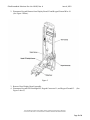
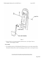
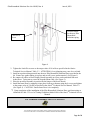
Elite Biomedical Solutions Doc. No. 10120, Rev. A June 4, 2012 Elite Biomedical Solutions
Replacement Door Installation Instructions
For Alaris® System Pump Modules
Pump Module #8100
Elite Biomedical Solutions Part #10360242
CAUTION
Utilize a static free environment when working on any electronic/electrical device.
Door Replacement Instructions
1. Remove screws (4) from the Inner Door and remove Inner Door from Door/ Display Board
Assembly. (See Figure 1 below).
Figure 1
The manufacturers listed are the holders of their respective names and/or trademarks, and are not to be taken as an endorsement or affiliation with Elite Biomedical Solutions. Page 1 of 4 Elite Biomedical Solutions Doc. No. 10120, Rev. A June 4, 2012 2. Disconnect Keypad Harness from Display Board J2 and Keypad Ground Wire J4.
(See Figure 2 below).
Figure 2
3. Remove Door Display Board Assembly.
4. Disconnect Keypad LED Backlight D8, Keypad Connector J1, and Keypad Ground J3.
Figure 2 above).
(See
The manufacturers listed are the holders of their respective names and/or trademarks, and are not to be taken as an endorsement or affiliation with Elite Biomedical Solutions. Page 2 of 4 Elite Biomedical Solutions Doc. No. 10120, Rev. A June 4, 2012 Figure 3
5. Remove Door Lever by unscrewing the Latch Pivot screw. (See Figure 3 above)
Caution: Torsion Spring is loaded.
Re-Assembly
1. Re-assemble with the new Elite Biomedical Solutions door in reverse order using the Elite
Biomedical Solutions Door Latch Torsion Spring provided in the kit. (See Figure 4 below)
The manufacturers listed are the holders of their respective names and/or trademarks, and are not to be taken as an endorsement or affiliation with Elite Biomedical Solutions. Page 3 of 4 Elite Biomedical Solutions Doc. No. 10120, Rev. A June 4, 2012 Use this feature
for the new Elite
Biomedical
Solutions spring
Latch Pivot
Screw
Figure 4
2. Tighten the Latch Pivot screw to the torque value of 10 in-lbs as specified in the Alaris®
Technical Service Manual, Table 5-3. ATTENTION: Over tightening may cause lever to bind.
3. Install new gasket tubing material into the new Elite Biomedical Solutions Door provided in the
kit. Ensure new gasket tubing in is place and cut off excess gasket material. (See Figure 1)
4. Re-connect all cables to Door Display Board Assembly in reverse order and install into new
Ardus Door. Trying not to crease the keypad ribbon cable. (See Figure 2).
5. Place the new door assembly in position on the hinges of the bezel chassis.
6. Install the Inner Door by snapping it into place from top to bottom using the 4 screws and tighten
to the torque value of 6 in-lbs as specified in the Alaris® Technical Service Manual, Table 5-3.
(See Figure 1). CAUTION: Ensure Inner Door is in completely.
7. Upon completion of the installation of the Elite Biomedical Solutions Door, perform testing as
identified in Table 5.5 Level of Testing Guidelines-Model 8100 of the Alaris® Technical Service
Manual.
For Technical Assistance, call (513) 659-0993
The manufacturers listed are the holders of their respective names and/or trademarks, and are not to be taken as an endorsement or affiliation with Elite Biomedical Solutions. Page 4 of 4