1
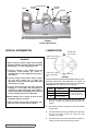
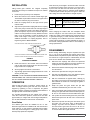
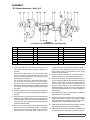
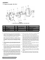
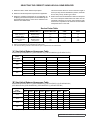
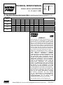
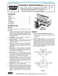
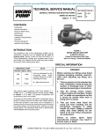
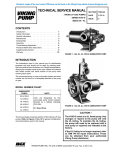
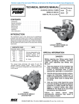
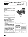
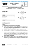
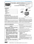
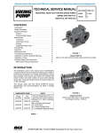
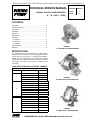
Electronic copies of the most current TSM issue can be found on the Viking Pump website at www.vikingpump.com
TECHNICAL SERVICE MANUAL
Viking® Helical Gear Reducers
“a”, “b”, and “c” sizes
SECTION
TSM 610
PAGE
1
ISSUE
F
CONTENTS
Introduction.......................................................................... 1
Special Information.............................................................. 2
Lubrication........................................................................... 2
Installation........................................................................... 3
Operation............................................................................. 3
Disassembly........................................................................ 3
Assembly
“A” Reducer....................................................................... 4
“B” Reducer....................................................................... 5
“C” Reducer.......................................................................6
Technical Data..................................................................... 7
Warranty.............................................................................. 8
FIGURE 1
“a” size helical gear reducer
INTRODUCTION
The illustrations used in this manual are for identification
purposes only and cannot be used for ordering parts. Obtain
a parts list from the factory or a Viking® representative.
Always give the complete name of the repair part and part
number along with the reducer part number when ordering
repair parts. The reducer part number is stamped on the
nameplate.
UNMOUNTED PUMP AND UNIT MODEL NUMBERS
“A”, “B” AND “C” SIZE REDUCERS
SIZE
A
B
C
PART NUMBER
RATIO
3-551-049-224
2.24:1
3-551-050-276
2.76:1
3-551-051-343
3.43:1
3-551-052-417
4.17:1
3-551-054-187
3-551-055-224
3-551-001-276
3-551-002-340
3-551-003-419
3-551-004-506
3-551-005-627
3-551-007-765
1.87:1
2.24:1
2.76:1
3.40:1
4.19:1
5.06:1
6.27:1
7.65:1
3-551-056-221
2.21:1
3-551-032-280
2.80:1
3-551-008-331
3.31:1
3-551-009-421
4.21:1
3-551-010-508
5.08:1
3-551-011-624
6.24:1
3-551-012-795
7.95:1
FIGURE 2
“B” size Helical gear reducer
FIGURE 3
“C” size helical gear reducer
VIKING PUMP, INC. • A Unit of IDEX Corporation • Cedar Falls, IA 50613 USA
HELICAL REDUCER
LOW SPEED
COUPLING
HIGH SPEED
COUPLING
MOTOR
BRACKET
PUMP
BASEPLATE
NOTE: UNIT FURNISHED WITH COUPLING GUARDS AS STANDARD
FIGURE 4
TYPICAL Installation
SPECIAL INFORMATION
LUBRICATION
breather vent
(oil fillhole)
lower hole oil level
DANGER !
plug
“a” reducer
Before opening any Viking pump liquid chamber
(pumping chamber, reservoir, relief valve adjusting
cap fitting etc.) , or drive equipment be sure:
1.
That any pressure in the chamber has been
completely vented through the suction or
discharge lines or other appropriate openings or
connections.
2.That the driving means (motor, turbine, engine,
etc.) has been “locked out” or made nonoperational so that it cannot be started while work
is being done on pump.
3.That you know what liquid the pump has been
handling or in the reducer and the precautions
necessary to safely handle the liquid. Obtain a
material safety data sheet (MSDS) for the liquid to
be sure these precautions are understood.
4.Before starting unit or reducer, be sure all drive
equipment guards are in place.
Failure to follow above listed precautionary measures may result in serious injury or death.
lower hole oil level
plug
drain plug
“b & c” Reduc-
ers
figure 5
VIKING GEAR REDUCERS ARE SHIPPED WITHOUT OIL.
BEFORE OPERATING THE REDUCER, BE SURE TO
ADD THE PROPER AMOUNT AND TYPE OF LUBRICANT.
CAUTION! DO NOT OVER FILL. See chart blow.
REDUCER
SIZE
A
3/8 PT. (6 OZ.)
B
1/2 PT. (8 OZ.)
C
2 & 1/4 PT. (36 OZ.)
QUANTITY
MOTOR OIL TYPE &
SERVICE
Use SAE 30 Above 32ºF
Use SAE 10W Below 32ºF
1. Remove the breather and add the proper lubricant for
the type of service and quantity given after each size
reducer.
2. After the first 100 hours of operation, drain and refill with
new lubricant.
3. Check the lubricant level every 2000 hours of operation
or every six months, which ever occurs first. Add
lubricant as necessary.
4. Once each year drain and refill. If the reducer is outdoors,
change to proper lubricant each spring and fall.
SECTION TSM
610
ISSUE
G
PAGE 2 OF 8
INSTALLATION
Viking helical gear reducers are shipped completely
assembled and ready for installation except for the addition
of lubricant.
1. Fasten the pump securely to the baseplate.
2. Mount the reducer on the reducer bracket finger tight.
The breather cap should be located on the upper side of
the reducer and drain plug on the bottom.
3. Place the coupling halves on the high and low speed
reducer shafts.
4. Align the low speed shaft coupling half with the coupling
half on the pump or driver shaft. Use a straight edge to
align the coupling as in figure 6. A C-clamp, clamped over
pieces of keystock, may be used to hold this alignment
until the mounting bracket is securely bolted to the base
plate. It may be necessary to shim the bracket to the
extact center height of the pump or driven shaft. For
additional information on coupling alignment, refer to
Engineering Service Bulletin #ESB 61.
USE STRAIGHT EDGE. THESE SURFACES MUST BE PARALLEL
Gear ratios may be changed in all reducers within each size
by selecting the proper pinion and gear of a common ratio.
A pinion from one ratio cannot be used with a gear from a
different ratio. Certain “B” and “C” reducers require additional
or different parts besides the pinion and gear to make the
ratio change. See the chart below for changes required.
SIZE
B
C
RATIO
CHANGES REQUIRED
6.27 to 1
Snap ring for pinion and shaft
7.65 to 1
Two spacers ( A larger O.D. than is used
on other ratios) and gear shaft
7.95 to 1
Gear shaft and a longer key, also a snap
ring.
NOTE: SNAP RING IS FURNISHED WITH “C” 7.95 TO 1 PINION AND
SHAFT
When changing the reducer ratio, the nameplate should
also be changed to new ratio reducer part number. After
making any output or input speed change (complete reducer
or gear ratio changes), a check should be made to ensure
the couplings are of sufficient size for the conditions which
reducer will be operating. For ratios available see page 1 of
this manual, catalog specification sheet or consult factory or
Viking representative.
DISASSEMBLY
CHECK WIDTH BETWEEN THESE SURFACES WITH INSIDE CALIPERS TO BE
CERTAIN THE FACES ARE EQUAL DISTANCE APART AND PARALLEL
figure 6
coupling alignment
5. Rotate the reducer in the “banana” slots of the bracket
until the high speed coupling half is at the exact center
height of the motor coupling half.
6. Securely tighten the reducer to the bracket .
7. Align the high speed shaft coupling and fasten the motor
securely to base plate.
CAUTION ! : DO NOT EXCEED RECOMMENDED MAXIMUM
HORSEPOWER, SEE CATALOG SPECIFICATION SHEET.
DO NOT OPERATE BEFORE ADDING LUBRICANT.
OPERATION
After the first few hours of operation, inspect reducer for
leaks. If leakage between gear case and cover cannot be
stopped by tightening of nuts or capscrews, the gasket
should be replaced. Leakage around either shaft indicates a
damaged lip seal which should be replaced.
The operating temperature on the outside of the reducer
case, after a few hours operation, should not be more than
approximately 75º F higher than surrounding air temperature.
The oil within the Reducer should never exceed 200º F.
Gear Ratios
Four different gear ratios are available for the “A” size
Reducers. Eight ratios are available for “B” size reducers and
seven ratios for “C” size reducers. Complete reducers within
a size may be interchanged on a Viking pump unit to obtain
desired pump speeds and capacities.
Before starting disassembly, study the exploded view (see
Fig. 7, 8 or 9) for the particular size reducer that is being
disassembled to help determine parts relationship. The parts
are indexed in a logical sequence of disassembly and will
prove to be a valuable aid in dismantling the reducer.
1. Disconnect the couplings and remove the capscrews
holding the mounting bracket to the base. Remove the
coupling halves and bracket from the reducer.
2. Remove the breather and drain plugs. Drain all lubricant
from the reducer.
3. Remove the capscrews from the gear case halves.
4. Tap firmly and alternately on the gear shaft and pinion
shaft. This will separate the reducer halves.
5. With two screwdrivers at opposite sides, carefully pry
the reducer cover loose from internal ball bearings. DO
NOT FORCE. Be careful not to damage the gasket or
gasket surface.
6. Grasp the pinion and gear shafts and pull both
assemblies simultaneously from the case or cover.
7. Use a conventional gear or bearing puller to remover the
bearing from gear shaft. Remove the bevelled spacer on
“B” and “C” size reducers. Press the shaft from the gear.
8. Use a puller and remove bearings from the pinion shaft.
Remove the spacer from “B” size 7.65 to 1 ratio from the
pinion shaft.
9. Remove the lip seals from the gear case halves (cover
and case) only if they show signs of deterioration or
damage. Lip seals must be pressed or driven out
from the inside of gear case and cover on “B” and “C”
reducers. “A” size reducer may have lip seals pressed in
or out from either side of gear case half.
SECTION TSM
610
ISSUE
G
PAGE 3 OF 8
ASSEMBLY
“A” Reducer Assembly - See Fig.7
figure 7
“A” size helical gear reducer - exploded view
ITEM
1.
NAME OF PART
ITEM
NAME OF PART
ITEM
NAME OF PART
1
Breather
6
Gear Case Half (Set-2)
11
Gear Shaft
2
Pipe Plug (Set-3)
7
Gasket
12
Pinion & Shaft
3
Capscrew (Set-6)
8
Ball Bearing (Set-4)
13
Lip Seal (Set-2)
4
Nut (Set-6)
9
Gear
14
Cover (Set-2)
5
Dowel Pin (Set-2)
10
Key
Install ball bearings on the pinion shaft. Be sure the
single row bearings are seated firmly against the shoulders
on the pinion shaft.
2. Install the square key in the gear shaft and press the
gear into place.
3. Be sure the gear is centered on the shaft. Install the ball
bearings on each side of the gear. Be sure the bearings
are seated firmly against the gear and the shaft is still
centered.
4. If the lip seal has been removed during disassembly,
place the gear case halves, gasket faces down, on a
surface which will not mar the face. Put gasket sealer on
O.D. of lip seals. Drive new lip seals into the gear case
halves (lip towards inside of reducer) with a wood block
covering entire lip seal. Drive evenly until the lip seals
are flush with the outer face of the gear case halves.
5. If steel covers have been removed during disassembly,
install one cover in the bore of the gear case half opposite
the pinion shaft extension. This cover should be flush
with outer edge of case. Install a second cover in the bore
of the gear case half, opposite the gear shaft extension
.090 below the surface of the gear case. NOTE: Coat the
side of the covers with sealer and drive the cover from
the inside of case towards outside of case.
SECTION TSM
610
ISSUE
G
PAGE 4 OF 8
6. Apply lubricant to the lip seal sealing surfaces.
7.
Block the gear case, open side up, to provide at least 2”
clearance between the case and the assembly bench.
8. Make certain the pinion and gear shaft keyways are
free of burrs and sharp edges to prevent damaging the
sealing surfaces in the lip seals.
9. Take the pinion and gear assemblies, mesh the gear
teeth and insert simultaneously into the gear case half.
Rotate the gear shaft slightly as it is pushed through the
lip seal. Tap the end of pinion shaft and gear shaft with a
hard wood block to seat the bearings in the counterbores.
10. Place gasket on the gear case. If the gasket is damaged,
discard it and use a new gasket.
11. Align the gear case half with ends of the pinion and
gear shafts, and carefully pass the other half into place.
Rotate the pinion shaft during assembly. Tap the gear
case with a hard wood block to seat the bearings.
12. Install the six capscrews and nuts and tighten securely,
alternating around gear case to prevent distortion.
13. Install drain plug. Be sure the proper amount and type of
lubricant is added. See “Lubrication” instructions, page 2.
ASSEMBLY
“B” Reducer Assembly - See Fig. 8
figure 8
“B” size helical gear reducer - exploded view
ITEM
NAME OF PART
ITEM
NAME OF PART
ITEM
NAME OF PART
1
Drain Plug
11
Ball Bearing
19
Snap Ring (for 6.27 to 1 ratio only)
2
Breather
12
Ball Bearing
20
Pinion and Shaft
3
Pipe Plug (Set-2)
13
Spacer (7.65 to 1 Ratio - 2 Req’d)
21
Snap Ring (Set-2)
4
Capscrew (Set-7)
14
Gear
22
Lip Seal (Set-2)
5
Nut (Set-7) “B” only
15
Key
23
Gear Case
6
Dowel Pin Locating (Set-2)
16
Gear Shaft
7
Gear Case Cover
17
Ball Bearing
8
Gasket
18
Ball Bearing
1. Install the ball bearing on the pinion and shaft. Be sure
the bearings are seated firmly against the shoulders on
the shaft.
NOTE: The “B” reducer with 6.27 to 1 ratio requires a snap
ring. This snap ring must be installed in the groove on the
shaft prior to bearing assembly. The bearing should be
seated against the snap ring.
The “B” reducer with 7.65 to 1 ratio requires two spacers,
one on the pinion and shaft and one on the gear shaft.
The spacer for the pinion and shaft should be installed
with bevelled edge toward bearing. Install the ball bearing
on the pinion and shaft, seating the bearing firmly against
the spacer.
2. Install the square key in the gear shaft and press the gear
into place. Be sure the gear seats against the shoulder on
the shaft.
3. Place the spacer on the gear shaft with the bevelled edge
toward the gear. Install the bearing over the gear shaft and
seat firmly against the spacer. Install a second bearing on
the large end of the gear shaft and seat the bearing firmly
against the shaft shoulder.
4. If the lip seals have removed during disassembly place
the gear case and cover, gaskets face down, on a surface
which will not mar the face. Be sure the snap rings are in
the face and cover. Put gasket sealer on the O.D. of the
5.
lip seals. Drive new lip seals with lip toward the inside of
the reducer, in place against the snap rings. Use a wood
block covering entire lip seal and drive evenly. Apply
lubricant to lip seal surfaces.
Block the gear case, open side up, to provide at least 3¼”
clearance between the case and the assembly bench.
6. Make certain the pinion and gear shaft keyways are free
of burrs and sharp edges to prevent damaging the lip seal
sealing surfaces. Take the pinion and gear assemblies,
mesh the gear teeth, and insert simultaneously into
the gear case half. Rotate the gear shaft slightly as it is
pushed through lip seal. Tap end of the pinion shaft and
gear shaft with hardwood block to seat the bearings in
counter bores.
7. Place gasket on the gear case. If the gasket is damaged,
discard it and use a new gasket.
8. Align the gear case cover with the ends of pinion and gear
shafts, and carefully push the cover into place. Rotate
the pinion shaft during assembly. Tap the cover with a
hardwood block to seat the bearings in the cover.
9. Install the seven capscrews and nuts and tighten securely,
alternating around gear case to prevent distortion.
10. Install the drain plug. Be sure the reducer is filled with the
proper lubricant. See “Lubrication” instructions, page 2.
SECTION TSM
610
ISSUE
G
PAGE 5 OF 8
ASSEMBLY
“C” Reducer Assembly - See Fig. 9
figure 9
“C” size helical gear reducer - exploded view
ITEM
1
2
3
4
5
6
NAME OF PART
ITEM
Drain Plug
Breather
Pipe Plug (Set-2)
Capscrew (Set-2)
Dowel Pin Locating (Set-2)
Gear Case Cover
7
9
10
11
12
13
NAME OF PART
Gasket
Ball Bearing (Double Row)
Ball Bearing (Single Row)
Spacer
Gear
Key
1. Install the ball bearing on the pinion shaft; the double row
bearing on the small diameter end, and the single row
bearing on the large diameter end. Be sure the bearings
are seated firmly against the shoulders on the shaft.
NOTE: The pinion and shaft for “C” reducer (7.95 to 1
ratio) is furnished with a snap ring. This snap ring must
be installed in the groove on the shaft prior to bearing
assembly. The bearing should be seated against the snap
ring.
2. Install the square key in the gear shaft and press the gear
into place. Be sure the gear seats against the shoulder on
the shaft.
3. Place the spacer on the gear shaft with bevelled edge
toward the gear. Install the bearing over gear shaft and
seat firmly against the spacer. Install a second bearing
on large end of the gear shaft and seat the bearing firmly
against the shaft shoulder.
4. If the lip seals have been removed during disassembly
place gear case and cover, gaskets face down, on surface
which will not mar the face. Be sure the snap rings are in
the face and cover. Put gasket sealer on the O.D. of lip
seals. Drive new lip seals with lip toward the inside of the
reducer, in place against the snap rings. Use a wood block
covering entire lip seal and drive evenly. Apply lubricant to
lip seal surfaces.
SECTION TSM
610
ISSUE
G
PAGE 6 OF 8
ITEM
14
15
16
17
18
19
NAME OF PART
Gear Shaft
Ball Bearing (Double Row)
Ball Bearing (Single Row)
Pinion and Shaft
Snap Ring (Set-2)
Lip Seal (Set-2)
5. Block the gear case, open side up, to provide at least
3¾” clearance between case and assembly bench.
6. Make certain the pinion and gear shaft keyways are free
of burrs and sharp edges to prevent damaging the lip seal
sealing surfaces. Take the pinion and gear assemblies,
mesh the gear teeth, and insert simultaneously into the
gear case half. Rotate the gear shaft slightly as it is
pushed through the lip seal. Tap the end of the pinion
shaft and gear shaft with hardwood block to seat the
bearings in the counter bores.
7. Place the gasket on gear case. If the gasket is damaged,
discard it and use a new gasket.
8. Align the gear case cover with the ends of the pinion
and gear shafts, and carefully push the cover into place.
Rotate the pinion shaft during assembly. Tap the cover
with a hardwood block to seat the bearings in cover.
9. Install the seven capscrews and nuts and tighten
securely, alternating around the gear case to prevent
distortion.
10. Install the drain plug. Be sure the reducer is filled with
proper lubricant. See “Lubrication” instructions, page 2.
SELECTING THE CORRECT VIKING HELICAL GEAR REDUCER
This service factor takes into account the time length of
service per day, the load classification (uniform, moderate
shock, heavy shock), and the type of drive.
1. Determine ratio to obtain desired output speed.
2. Determine actual horsepower requirements of application.
3. Determine equivalent horsepower for the application by
multiplying the actual horsepower to be transmitted by the
appropriate service factors, which can be obtained in the
Service Factor Table below.
4. Refer to the recommended maximum reducer horsepower
line in the horsepower tables below and make sure the
equivalent horsepower for a given input speed and ratio
is less than or equivalent to the maximum recommended
horsepower shown in the chart.
Service Factor Table
CHARACTER OF
DRIVEN LOAD (2) (3)
Uniform
Moderate Shock
Heavy Shock
Uniform
Moderate Shock
Heavy Shock
POWER SOURCE (1) (3)
Electric Motor,
Steam Turbine, or
Hydraulic Motor
Multi-Cylinder
Internal Combustion
Engine
INTERMITTENT
UP TO 3 HRS. A DAY
.8
1.0
1.5
1.0
1.25
1.75
8-10 HRS.
A DAY
1.0
1.25
1.75
1.25
1.5
2.0
24 HRS.
A DAY
1.25
1.5
2.0
1.5
1.75
2.25
1. For applications driven by single cylinder engines, refer to factory for other service factors.
2. Rotary pump applications are considered as uniform loads.
3. Use of belt or chain type drives to either reducer input or output shaft is not recommended.
“A” Size Helical Reducer Horsepower Table
Part No./Ratio (3-551-049-224/2.24:1) (3-551-050-276/2.76:1) (3-551-051-343/3.43:1) (3-551-052-417/4.17:1)
HIGH SPEED
SHAFT
INPUT RPM (1)
VIKING GEAR REDUCER RATIOS “A” SIZE
2.24:1
2.76:1
3.43:1
4.17:1
780
640
520
420
LOW SPEED SHAFT RPM
6.1
4.9
3.8
3.1
MAXIMUM REDUCER HP
640
520
420
350
LOW SPEED SHAFT RPM
5.2
4.2
3.2
2.7
MAXIMUM REDUCER HP
520
420
350
280
LOW SPEED SHAFT RPM
1750
1450
1150
950
4.3
3.4
2.6
2.2
MAXIMUM REDUCER HP
420
350
280
230
LOW SPEED SHAFT RPM
3.6
2.9
2.2
1.8
MAXIMUM REDUCER HP
(1) For input speeds higher than 1750 RPM, consult the factory.
“B” Size Helical Reducer Horsepower Table
Part No./Ratio (3-551-054-187/1.87:1) (3-551-055-224/2.24:1) (3-551-001-276/2.76:1) (3-551-002-340/3.40:1)
(3-551-003-419/4.19:1) (3-551-004-506/5.06:1) (3-551-005-627/6.27:1) (3-551-007-765/7.65:1)
HIGH SPEED
SHAFT
INPUT RPM (1)
1750
1450
1150
950
VIKING GEAR REDUCER RATIOS “B” SIZE
1.87:1
2.24:1
2.76:1
3.40:1
4.19:1
5.06:1
6.27:1
7.65:1
950
780
640
520
420
350
280
230
19.0
17.0
15.0
13.0
11.0
9.5
7.6
6.4
LOW SPEED SHAFT RPM
MAXIMUM REDUCER HP
780
640
520
420
350
280
230
190
LOW SPEED SHAFT RPM
17.3
15.5
13.4
11.6
9.9
8.5
6.4
5.4
MAXIMUM REDUCER HP
640
520
420
350
280
230
190
155
LOW SPEED SHAFT RPM
16.5
14.0
11.6
10.1
8.5
7.3
5.3
4.4
MAXIMUM REDUCER HP
520
420
350
280
230
190
155
125
LOW SPEED SHAFT RPM
15.5
12.8
10.1
9.0
7.6
6.0
4.3
3.7
MAXIMUM REDUCER HP
1 For input speeds higher than 1750 RPM, consult the factory.
SECTION TSM
610
ISSUE
G
PAGE 7 OF 8
TECHNICAL SERVICE MANUAL
Viking® Helical Gear Reducers
“a”, “b”, and “c” sizes
SECTION
TSM 610
PAGE
8
ISSUE
F
“C” Size Helical Reducer Horsepower Table Part No./Ratio (3-551-056-221/2.21:1) (3-551-008-331/3.31:1)
(3-551- 009-421/4.21:1) (3-551-010-508/5.08:1) (3-551-011-624/6.24:1) (3-551-012-795/795:1) (3-551-032-280/2.80:1)
HIGH SPEED
SHAFT
INPUT RPM (1)
1750
1450
1150
950
VIKING GEAR REDUCER RATIOS “C” SIZE
2.21:1
2.80:1
3.31:1
4.21:1
5.80:1
6.24:1
7.95:1
780
49.8
640
45.3
520
40.1
420
29.1
640
43.5
520
36.6
420
30.0
350
24.7
520
39.0
420
32.8
350
26.8
280
22.1
420
32.4
350
27.2
280
22.2
230
18.3
350
26.6
280
22.3
230
18.2
190
15.0
280
19.7
230
16.7
190
13.8
155
11.4
220
18.0
180
15.2
145
12.6
120
10.4
LOW SPEED SHAFT RPM
MAXIMUM REDUCER HP
LOW SPEED SHAFT RPM
MAXIMUM REDUCER HP
LOW SPEED SHAFT RPM
MAXIMUM REDUCER HP
LOW SPEED SHAFT RPM
MAXIMUM REDUCER HP
(1) For input speeds higher than 1750 RPM, consult the factory.
WARRANTY
Viking warrants all products manufactured by it to be
free from defects in workmanship or material for a
period of one (1) year from date of startup, provided
that in no event shall this warranty extend more than
eighteen (18) months from the date of shipment from
Viking. The warranty period for Universal Seal series
pumps ONLY (Universal Seal models listed below) is
three (3) years from date of startup, provided that in
no event shall this warranty extend more than forty-two
(42) months from the date of shipment from Viking.
UNDER NO CIRCUMSTANCES SHALL VIKING BE
LIABLE UNDER THIS WARRANTY OR OTHERWISE
FOR
SPECIAL,
INCIDENTAL,
INDIRECT,
CONSEQUENTIAL OR PUNITIVE DAMAGES OF ANY
KIND, INCLUDING, BUT NOT LIMITED TO, LOST
OR UNREALIZED SALES, REVENUES, PROFITS,
INCOME, COST SAVINGS OR BUSINESS, LOST OR
UNREALIZED CONTRACTS, LOSS OF GOODWILL,
DAMAGE TO REPUTATION, LOSS OF PROPERTY,
LOSS OF INFORMATION OR DATA, LOSS OF
PRODUCTION, DOWNTIME, OR INCREASED
COSTS, IN CONNECTION WITH ANY PRODUCT,
EVEN IF VIKING HAS BEEN ADVISED OR PLACED
ON NOTICE OF THE POSSIBILITY OF SUCH
DAMAGES AND NOTWITHSTANDING THE FAILURE
OF ANY ESSENTIAL PURPOSE OF ANY PRODUCT.
THIS WARRANTY IS AND SHALL BE VIKING’S SOLE
AND EXCLUSIVE WARRANTY AND SHALL BE IN
LIEU OF ALL OTHER WARRANTIES, EXPRESS
OR IMPLIED, INCLUDING, BUT NOT LIMITED
TO, ALL WARRANTIES OF MERCHANTABILITY,
FITNESS FOR A PARTICULAR PURPOSE AND
NON-INFRINGEMENT ALL OF WHICH OTHER
WARRANTIES ARE EXPRESSLY EXCLUDED.
See complete warranty at www.vikingpump.com.
VIKING PUMP, INC. • A Unit of IDEX Corporation • Cedar Falls, IA 50613 USA
© 3/2013 Viking Pump Inc.
All rights reserved